EP3263279B1 - Maschine zur montage/demontage von feder-/dämpfereinheiten der aufhängung von fahrzeugen mit einer vereinfachten struktur - Google Patents
Maschine zur montage/demontage von feder-/dämpfereinheiten der aufhängung von fahrzeugen mit einer vereinfachten struktur Download PDFInfo
- Publication number
- EP3263279B1 EP3263279B1 EP17177905.1A EP17177905A EP3263279B1 EP 3263279 B1 EP3263279 B1 EP 3263279B1 EP 17177905 A EP17177905 A EP 17177905A EP 3263279 B1 EP3263279 B1 EP 3263279B1
- Authority
- EP
- European Patent Office
- Prior art keywords
- spring
- machine
- clamps
- supporting
- guiding element
- Prior art date
- Legal status (The legal status is an assumption and is not a legal conclusion. Google has not performed a legal analysis and makes no representation as to the accuracy of the status listed.)
- Active
Links
Images


Classifications
-
- B—PERFORMING OPERATIONS; TRANSPORTING
- B25—HAND TOOLS; PORTABLE POWER-DRIVEN TOOLS; MANIPULATORS
- B25B—TOOLS OR BENCH DEVICES NOT OTHERWISE PROVIDED FOR, FOR FASTENING, CONNECTING, DISENGAGING OR HOLDING
- B25B27/00—Hand tools, specially adapted for fitting together or separating parts or objects whether or not involving some deformation, not otherwise provided for
- B25B27/14—Hand tools, specially adapted for fitting together or separating parts or objects whether or not involving some deformation, not otherwise provided for for assembling objects other than by press fit or detaching same
- B25B27/30—Hand tools, specially adapted for fitting together or separating parts or objects whether or not involving some deformation, not otherwise provided for for assembling objects other than by press fit or detaching same positioning or withdrawing springs, e.g. coil or leaf springs
- B25B27/302—Hand tools, specially adapted for fitting together or separating parts or objects whether or not involving some deformation, not otherwise provided for for assembling objects other than by press fit or detaching same positioning or withdrawing springs, e.g. coil or leaf springs coil springs other than torsion coil springs
- B25B27/304—Hand tools, specially adapted for fitting together or separating parts or objects whether or not involving some deformation, not otherwise provided for for assembling objects other than by press fit or detaching same positioning or withdrawing springs, e.g. coil or leaf springs coil springs other than torsion coil springs by compressing coil springs
-
- B—PERFORMING OPERATIONS; TRANSPORTING
- B60—VEHICLES IN GENERAL
- B60G—VEHICLE SUSPENSION ARRANGEMENTS
- B60G2206/00—Indexing codes related to the manufacturing of suspensions: constructional features, the materials used, procedures or tools
- B60G2206/01—Constructional features of suspension elements, e.g. arms, dampers, springs
- B60G2206/90—Maintenance
- B60G2206/92—Tools or equipment used for assembling
- B60G2206/921—Coil spring compressor
Definitions
- the present invention relates to a machine for assembling/disassembling spring/damper units of suspensions of vehicles having a simplified structure.
- Equipment of the manual type and of the automatically actuated type is known for performing these interventions.
- damper dismantling machines are constituted essentially by a frame for supporting a bracket for the resting of the lower end of the spring and a pneumatic cylinder which acts in a vertical direction and the movable stem of which translates alternately a horizontal crossmember that is connected to two clamps adapted to be tightened at the upper end of the spring.
- the crossmember is associated so that it can slide along two vertical guides.
- Each clamp is pivoted so that it can rotate about a horizontal axis at the end of a respective arm which oscillates on the horizontal plane connected to the crossmember, which translates the clamps alternately in a vertical direction. In this manner, the position of the clamps can adapt to different diameters and inclinations of the turns of the spring.
- the actuation of the pneumatic cylinder allows to compress or release the spring respectively for the disassembly or assembly of the damper.
- FR 2 055 745 discloses a damper dismantling machine having a combination of features as set forth in the pre-characterizing portion of the appended claim 1.
- the aim of the present invention is to eliminate the drawbacks noted above of the background art, providing a machine for assembling/disassembling spring/damper units having a simplified structure and a reduced number of components, so to reduce its production times and costs.
- an object of the present invention is to provide a machine for assembling/disassembling spring/damper units that is safe and easy in use as well as reliable over time.
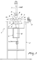
- the reference numeral 1 designates generally a machine for assembling/disassembling spring/damper units of suspensions of vehicles having a simplified structure.
- the machine 1 comprises a frame 2 for supporting means 3 for the lower resting contact of a spring 101 of a conventional spring/damper unit, 100, of the type used in the suspensions of vehicles, means 4 for gripping from above the spring 101, and means 5 for actuating with an alternating translational motion along a substantially vertical work direction D which are associated with the grip means 4 in order to move them toward/away from the resting means 3 so as to obtain the compression/release of the spring 101 to replace the damper 102 of the unit 100.
- the frame 2 comprises a set of assembled profiles which form, in the lower part, a ground resting element and, in the upper part, the work area, which is enclosed by appropriate protections 16 of the known type.
- the resting means 3 comprise at least one bracket 6 which is contoured as a function of the geometry of the spring 101 on which one must intervene, supported in a cantilever manner by the frame 2. It is possible to provide different brackets 6 which have different configurations to be used alternatively as a function of the geometry of the spring 101. In the illustrated embodiment, the machine 1 is provided with two brackets 6 which can be arranged alternately in the work region.
- the machine 1 comprises a single element 7 for the sliding guiding of the grip means 4 along a translation axis A which substantially coincides with the work direction D.
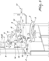
- the grip means 4 comprise a supporting body 8 which is associated slidingly along the guiding element 7 and an element 9 which supports a pair of clamps 10 that can be associated with the spring 101 that is associated with the supporting body 8 so that it can oscillate about a horizontal oscillation axis B. Furthermore, the clamps 10 are associated with the supporting element 9 so that they are pivoted about respective rotation axes R which are substantially perpendicular to the plane of arrangement of said clamps.
- the supporting element 9 is constituted by a block which is pivoted to the supporting body 8 and below which there is an arc-like sector to the ends of which the clamps 10 are pivoted.
- the oscillation of the supporting element 9 together with the clamps 10 about the oscillation axis B allows the grip means 4 to adapt to different inclinations of the turns of the spring 101 and to vary their angular position as a function of its deformation during compression/release.
- the rotation of the camps 10 about the respective rotation axes are allowed to adjust their opening as a function of the diameter of the spring 101.
- the grip means 4 are used universally as the type of spring 101 on which one must intervene varies.
- Each clamp 10 is constituted by an arc-like portion which has a horizontal arrangement when the supporting element 9 is not rotated with respect to the supporting body 8.
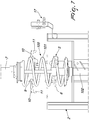
- the guiding element 7 has a tubular shape so as to form an internal longitudinal cavity and the actuation means 5 comprise a cylinder 12 that is supported by the lower part of the frame 2, the stem of which, not visible in the figures, can move along the longitudinal cavity of the guiding element 7.
- the actuation means 5 comprise a cylinder 12 that is supported by the lower part of the frame 2, the stem of which, not visible in the figures, can move along the longitudinal cavity of the guiding element 7.
- the actuation means 5 comprise a cylinder 12 that is supported by the lower part of the frame 2, the stem of which, not visible in the figures, can move along the longitudinal cavity of the guiding element 7.
- the actuation means 5 comprise a cylinder 12 that is supported by the lower part of the frame 2, the stem of which, not visible in the figures, can move along the longitudinal cavity of the guiding element 7.
- the actuation means 5 comprise a cylinder 12 that is supported by the lower part of the frame 2, the stem of which, not visible in the figures, can move along the longitudinal cavity of the
- the cylinder 12 is of the pneumatic type and is associated with an actuation circuit with corresponding safety devices, not shown in detail, which provides control elements 17 that can be operated by an operator.
- the stem of the cylinder 12 is substantially coaxial to the tubular guiding element 7, so that the work direction D and the translation axis A substantially coincide.
- the machine according to the invention can be used universally as the shape of the spring/damper unit changes, is practical and safe to use and is reliable over time.
Landscapes
- Engineering & Computer Science (AREA)
- Mechanical Engineering (AREA)
- Vehicle Body Suspensions (AREA)
Claims (4)
- Eine Maschine (1) zur Montage/Demontage von Feder-/ Dämpfereinheiten von Aufhängungen von Fahrzeugen, die Folgendes umfasst: einen Rahmen (2) zum Tragen von Mitteln (3) für den unteren Auflagekontakt einer Feder (101) einer Feder-/ Dämpfereinheit (100), Mittel (4) zum Greifen der Feder (101) von oben und Mittel (5) zum Antreiben mit einer alternierenden Translationsbewegung in einer im Wesentlichen vertikalen Arbeitsrichtung (D), die mit den Greifmitteln (4) verbunden sind; wobei die Maschine (1) ein einzelnes Element (7) zur Gleitführung der Greifmittel (4) entlang einer im Wesentlichen vertikalen Translationsachse (A) umfasst, und dadurch, dass die Greifmittel (4) einen tragenden Körper (8) umfassen, welcher gleitend entlang dem Führungselement (7) angeschlossen ist, und ein Element (9), das ein Paar von Klemmen (10) trägt, welche mit der Feder (101) verbunden werden können; wobei das tragende Element (9) so mit dem tragenden Körper (8) verbunden ist, dass es sich um eine im Wesentlichen horizontale Achse (B) drehen kann, und jede der Klemmen (10) so mit dem tragenden Element (9) verbunden ist, dass sie sich um eine entsprechende Rotationsachse (R) drehen kann, die im Wesentlichen senkrecht zur Anordnungsebene der Klemmen ist; dadurch gekennzeichnet, dass das Führungselement (7) eine Röhrenform hat, um einen länglichen inneren Hohlraum zu bilden, und dadurch, dass die Antriebsmittel (5) einen Zylinder (12) vom Pneumatiktyp umfassen, dessen entsprechender Schaft sich innerhalb des länglichen inneren Hohlraums bewegen kann, wobei der tragende Körper (8) in der Translation integral mit dem beweglichen Schaft gemacht wird durch mindestens einen Stift (15), der durch mindestens einen am Führungselement (7) geformten Längsschlitz (14) hindurchgeführt wird.
- Die Maschine (1) gemäß Anspruch 1, dadurch gekennzeichnet, dass der tragende Körper (8) eine Hülse umfasst, die gleitend mit der Außenseite des Führungselements (7) verbunden ist.
- Die Maschine (1) gemäß Anspruch 1, dadurch gekennzeichnet, dass der Schaft des Zylinders (12) und das Führungselement (7) im Wesentlichen koaxial sind, wodurch die Arbeitsrichtung (D) und die Translationsachse (A) im Wesentlichen zusammenfallen.
- Die Maschine (1) gemäß einem oder mehreren der obigen Ansprüche, dadurch gekennzeichnet, dass jede der Klemmen (10) ein Paar einander entgegengesetzter Profile (11) umfasst, die nach unten ragen und ausgebildet sind, um die entsprechende Wicklung der Feder (101) aufzunehmen.
Applications Claiming Priority (1)
| Application Number | Priority Date | Filing Date | Title |
|---|---|---|---|
| ITUA2016A004667A ITUA20164667A1 (it) | 2016-06-27 | 2016-06-27 | Macchina per il montaggio/smontaggio di gruppi molla-ammortizzatore di sospensioni di veicoli a struttura semplificata. |
Publications (2)
| Publication Number | Publication Date |
|---|---|
| EP3263279A1 EP3263279A1 (de) | 2018-01-03 |
| EP3263279B1 true EP3263279B1 (de) | 2021-12-15 |
Family
ID=57209796
Family Applications (1)
| Application Number | Title | Priority Date | Filing Date |
|---|---|---|---|
| EP17177905.1A Active EP3263279B1 (de) | 2016-06-27 | 2017-06-26 | Maschine zur montage/demontage von feder-/dämpfereinheiten der aufhängung von fahrzeugen mit einer vereinfachten struktur |
Country Status (2)
| Country | Link |
|---|---|
| EP (1) | EP3263279B1 (de) |
| IT (1) | ITUA20164667A1 (de) |
Families Citing this family (1)
| Publication number | Priority date | Publication date | Assignee | Title |
|---|---|---|---|---|
| CN120395735B (zh) * | 2025-04-21 | 2025-10-24 | 天津百诚阀门制造股份有限公司滨海新区设计分公司 | 阀门扇形执行机构弹簧缸装配拆卸一体机 |
Citations (1)
| Publication number | Priority date | Publication date | Assignee | Title |
|---|---|---|---|---|
| DE3021084A1 (de) * | 1980-06-04 | 1981-12-24 | August Bilstein GmbH & Co KG, 5828 Ennepetal | Federspanngeraet |
Family Cites Families (4)
| Publication number | Priority date | Publication date | Assignee | Title |
|---|---|---|---|---|
| FR2055745A1 (de) * | 1969-08-07 | 1971-04-30 | Lebre Charles | |
| DE2813381C2 (de) * | 1978-03-28 | 1982-12-30 | Horst 7730 Villingen-Schwenningen Klann | Druckfedernspanner |
| DE102006003284B3 (de) * | 2006-01-23 | 2007-07-05 | Klann-Spezial-Werkzeugbau-Gmbh | Vorrichtung zum Spannen einer Schraubenfeder eines Federdämpferbeines |
| US8112856B2 (en) * | 2008-08-05 | 2012-02-14 | Yakita Metal Industry Co., Ltd. | Clamp of anti-vibration spring |
-
2016
- 2016-06-27 IT ITUA2016A004667A patent/ITUA20164667A1/it unknown
-
2017
- 2017-06-26 EP EP17177905.1A patent/EP3263279B1/de active Active
Patent Citations (1)
| Publication number | Priority date | Publication date | Assignee | Title |
|---|---|---|---|---|
| DE3021084A1 (de) * | 1980-06-04 | 1981-12-24 | August Bilstein GmbH & Co KG, 5828 Ennepetal | Federspanngeraet |
Also Published As
| Publication number | Publication date |
|---|---|
| EP3263279A1 (de) | 2018-01-03 |
| ITUA20164667A1 (it) | 2017-12-27 |
Similar Documents
| Publication | Publication Date | Title |
|---|---|---|
| KR101636684B1 (ko) | 긴 가공물을 우측 및 좌측으로 굽힘 가공하기 위한 금형 및 상대 금형 방식의 벤딩 머신 | |
| EP3575112A1 (de) | Reifenwechselmaschine | |
| EP2987661B1 (de) | Vorrichtung zur montage- und demontage eines bereiften rades sowie maschine mit solch einer vorrichtung | |
| CN105235456A (zh) | 用于装配和移除轮胎的机器和方法 | |
| KR101555320B1 (ko) | 쇽 업소버의 스프링 압축장치가 일체화된 샵 프레스 | |
| CN105235455A (zh) | 用于装配和移除轮胎的机器和方法 | |
| US9132706B2 (en) | Device for locking wheel rims for vehicles on repair workshop machines, particularly tyre-changing machines or the like | |
| EP3263279B1 (de) | Maschine zur montage/demontage von feder-/dämpfereinheiten der aufhängung von fahrzeugen mit einer vereinfachten struktur | |
| CN108161417B (zh) | 一种汽车减震器弹簧拆装方法 | |
| EP2735405B1 (de) | Verbesserte Presse zur reversiblen Demontage von Autostoßdämpfern | |
| KR102296707B1 (ko) | 트롤리선 굽힘 공구 | |
| EP3738715B1 (de) | Vorrichtung zur abstützung von federdämpferanordnungen für maschinen zur montage/demontage von fahrzeugaufhängungen | |
| EP2842686A1 (de) | Spannvorrichtung | |
| US9610812B2 (en) | Tire bead extraction device for tire-changing machines | |
| CN104384921A (zh) | 一种适用于弹力较大的压缩弹簧组件的装配设备及其装配方法 | |
| EP4035835B1 (de) | Verankerungsvorrichtung für feder-dämpfer-anordnungen für maschinen zur montage/demontage von fahrzeugaufhängungen | |
| CN208343556U (zh) | 一种纸箱制造加工工具 | |
| EP2361163B1 (de) | Vorrichtung zum geraderichten von metallprofilen und dergleichen sowie einstellungsverfahren für geradericht elemente in solchen vorrichtungen | |
| EP3098092B1 (de) | Spindel für reifenwechselmaschinen | |
| US20190118359A1 (en) | Adaptor and method for motorized operation of a spring compressor | |
| EP2848593B1 (de) | Formhaltersystem für eine hohlglaswarenformmaschine | |
| EP3095560B1 (de) | Vorrichtung zum bewegen der schwenkhebel einer radaufhängung von fahrzeugen | |
| ITBI20130008A1 (it) | Apparecchiatura smonta-monta gomme | |
| ITUA20164666A1 (it) | Macchina per il montaggio/smontaggio di gruppi molla-ammortizzatore di sospensioni di veicoli a sicurezza incrementata. | |
| CN104385210A (zh) | 发动机摇臂安装台 |
Legal Events
| Date | Code | Title | Description |
|---|---|---|---|
| PUAI | Public reference made under article 153(3) epc to a published international application that has entered the european phase |
Free format text: ORIGINAL CODE: 0009012 |
|
| STAA | Information on the status of an ep patent application or granted ep patent |
Free format text: STATUS: THE APPLICATION HAS BEEN PUBLISHED |
|
| AK | Designated contracting states |
Kind code of ref document: A1 Designated state(s): AL AT BE BG CH CY CZ DE DK EE ES FI FR GB GR HR HU IE IS IT LI LT LU LV MC MK MT NL NO PL PT RO RS SE SI SK SM TR |
|
| AX | Request for extension of the european patent |
Extension state: BA ME |
|
| STAA | Information on the status of an ep patent application or granted ep patent |
Free format text: STATUS: REQUEST FOR EXAMINATION WAS MADE |
|
| 17P | Request for examination filed |
Effective date: 20180601 |
|
| RBV | Designated contracting states (corrected) |
Designated state(s): AL AT BE BG CH CY CZ DE DK EE ES FI FR GB GR HR HU IE IS IT LI LT LU LV MC MK MT NL NO PL PT RO RS SE SI SK SM TR |
|
| STAA | Information on the status of an ep patent application or granted ep patent |
Free format text: STATUS: EXAMINATION IS IN PROGRESS |
|
| 17Q | First examination report despatched |
Effective date: 20181205 |
|
| GRAP | Despatch of communication of intention to grant a patent |
Free format text: ORIGINAL CODE: EPIDOSNIGR1 |
|
| STAA | Information on the status of an ep patent application or granted ep patent |
Free format text: STATUS: GRANT OF PATENT IS INTENDED |
|
| INTG | Intention to grant announced |
Effective date: 20210707 |
|
| GRAS | Grant fee paid |
Free format text: ORIGINAL CODE: EPIDOSNIGR3 |
|
| GRAA | (expected) grant |
Free format text: ORIGINAL CODE: 0009210 |
|
| STAA | Information on the status of an ep patent application or granted ep patent |
Free format text: STATUS: THE PATENT HAS BEEN GRANTED |
|
| AK | Designated contracting states |
Kind code of ref document: B1 Designated state(s): AL AT BE BG CH CY CZ DE DK EE ES FI FR GB GR HR HU IE IS IT LI LT LU LV MC MK MT NL NO PL PT RO RS SE SI SK SM TR |
|
| REG | Reference to a national code |
Ref country code: GB Ref legal event code: FG4D Ref country code: CH Ref legal event code: EP |
|
| REG | Reference to a national code |
Ref country code: DE Ref legal event code: R096 Ref document number: 602017050851 Country of ref document: DE |
|
| REG | Reference to a national code |
Ref country code: IE Ref legal event code: FG4D |
|
| REG | Reference to a national code |
Ref country code: AT Ref legal event code: REF Ref document number: 1455131 Country of ref document: AT Kind code of ref document: T Effective date: 20220115 |
|
| REG | Reference to a national code |
Ref country code: LT Ref legal event code: MG9D |
|
| REG | Reference to a national code |
Ref country code: NL Ref legal event code: MP Effective date: 20211215 |
|
| PG25 | Lapsed in a contracting state [announced via postgrant information from national office to epo] |
Ref country code: RS Free format text: LAPSE BECAUSE OF FAILURE TO SUBMIT A TRANSLATION OF THE DESCRIPTION OR TO PAY THE FEE WITHIN THE PRESCRIBED TIME-LIMIT Effective date: 20211215 Ref country code: LT Free format text: LAPSE BECAUSE OF FAILURE TO SUBMIT A TRANSLATION OF THE DESCRIPTION OR TO PAY THE FEE WITHIN THE PRESCRIBED TIME-LIMIT Effective date: 20211215 Ref country code: FI Free format text: LAPSE BECAUSE OF FAILURE TO SUBMIT A TRANSLATION OF THE DESCRIPTION OR TO PAY THE FEE WITHIN THE PRESCRIBED TIME-LIMIT Effective date: 20211215 Ref country code: BG Free format text: LAPSE BECAUSE OF FAILURE TO SUBMIT A TRANSLATION OF THE DESCRIPTION OR TO PAY THE FEE WITHIN THE PRESCRIBED TIME-LIMIT Effective date: 20220315 |
|
| REG | Reference to a national code |
Ref country code: AT Ref legal event code: MK05 Ref document number: 1455131 Country of ref document: AT Kind code of ref document: T Effective date: 20211215 |
|
| PG25 | Lapsed in a contracting state [announced via postgrant information from national office to epo] |
Ref country code: SE Free format text: LAPSE BECAUSE OF FAILURE TO SUBMIT A TRANSLATION OF THE DESCRIPTION OR TO PAY THE FEE WITHIN THE PRESCRIBED TIME-LIMIT Effective date: 20211215 Ref country code: NO Free format text: LAPSE BECAUSE OF FAILURE TO SUBMIT A TRANSLATION OF THE DESCRIPTION OR TO PAY THE FEE WITHIN THE PRESCRIBED TIME-LIMIT Effective date: 20220315 Ref country code: LV Free format text: LAPSE BECAUSE OF FAILURE TO SUBMIT A TRANSLATION OF THE DESCRIPTION OR TO PAY THE FEE WITHIN THE PRESCRIBED TIME-LIMIT Effective date: 20211215 Ref country code: HR Free format text: LAPSE BECAUSE OF FAILURE TO SUBMIT A TRANSLATION OF THE DESCRIPTION OR TO PAY THE FEE WITHIN THE PRESCRIBED TIME-LIMIT Effective date: 20211215 Ref country code: GR Free format text: LAPSE BECAUSE OF FAILURE TO SUBMIT A TRANSLATION OF THE DESCRIPTION OR TO PAY THE FEE WITHIN THE PRESCRIBED TIME-LIMIT Effective date: 20220316 |
|
| PG25 | Lapsed in a contracting state [announced via postgrant information from national office to epo] |
Ref country code: NL Free format text: LAPSE BECAUSE OF FAILURE TO SUBMIT A TRANSLATION OF THE DESCRIPTION OR TO PAY THE FEE WITHIN THE PRESCRIBED TIME-LIMIT Effective date: 20211215 |
|
| PG25 | Lapsed in a contracting state [announced via postgrant information from national office to epo] |
Ref country code: SM Free format text: LAPSE BECAUSE OF FAILURE TO SUBMIT A TRANSLATION OF THE DESCRIPTION OR TO PAY THE FEE WITHIN THE PRESCRIBED TIME-LIMIT Effective date: 20211215 Ref country code: SK Free format text: LAPSE BECAUSE OF FAILURE TO SUBMIT A TRANSLATION OF THE DESCRIPTION OR TO PAY THE FEE WITHIN THE PRESCRIBED TIME-LIMIT Effective date: 20211215 Ref country code: RO Free format text: LAPSE BECAUSE OF FAILURE TO SUBMIT A TRANSLATION OF THE DESCRIPTION OR TO PAY THE FEE WITHIN THE PRESCRIBED TIME-LIMIT Effective date: 20211215 Ref country code: PT Free format text: LAPSE BECAUSE OF FAILURE TO SUBMIT A TRANSLATION OF THE DESCRIPTION OR TO PAY THE FEE WITHIN THE PRESCRIBED TIME-LIMIT Effective date: 20220418 Ref country code: ES Free format text: LAPSE BECAUSE OF FAILURE TO SUBMIT A TRANSLATION OF THE DESCRIPTION OR TO PAY THE FEE WITHIN THE PRESCRIBED TIME-LIMIT Effective date: 20211215 Ref country code: EE Free format text: LAPSE BECAUSE OF FAILURE TO SUBMIT A TRANSLATION OF THE DESCRIPTION OR TO PAY THE FEE WITHIN THE PRESCRIBED TIME-LIMIT Effective date: 20211215 Ref country code: CZ Free format text: LAPSE BECAUSE OF FAILURE TO SUBMIT A TRANSLATION OF THE DESCRIPTION OR TO PAY THE FEE WITHIN THE PRESCRIBED TIME-LIMIT Effective date: 20211215 |
|
| PG25 | Lapsed in a contracting state [announced via postgrant information from national office to epo] |
Ref country code: PL Free format text: LAPSE BECAUSE OF FAILURE TO SUBMIT A TRANSLATION OF THE DESCRIPTION OR TO PAY THE FEE WITHIN THE PRESCRIBED TIME-LIMIT Effective date: 20211215 Ref country code: AT Free format text: LAPSE BECAUSE OF FAILURE TO SUBMIT A TRANSLATION OF THE DESCRIPTION OR TO PAY THE FEE WITHIN THE PRESCRIBED TIME-LIMIT Effective date: 20211215 |
|
| REG | Reference to a national code |
Ref country code: DE Ref legal event code: R097 Ref document number: 602017050851 Country of ref document: DE |
|
| PG25 | Lapsed in a contracting state [announced via postgrant information from national office to epo] |
Ref country code: IS Free format text: LAPSE BECAUSE OF FAILURE TO SUBMIT A TRANSLATION OF THE DESCRIPTION OR TO PAY THE FEE WITHIN THE PRESCRIBED TIME-LIMIT Effective date: 20220415 |
|
| PLBE | No opposition filed within time limit |
Free format text: ORIGINAL CODE: 0009261 |
|
| STAA | Information on the status of an ep patent application or granted ep patent |
Free format text: STATUS: NO OPPOSITION FILED WITHIN TIME LIMIT |
|
| PG25 | Lapsed in a contracting state [announced via postgrant information from national office to epo] |
Ref country code: DK Free format text: LAPSE BECAUSE OF FAILURE TO SUBMIT A TRANSLATION OF THE DESCRIPTION OR TO PAY THE FEE WITHIN THE PRESCRIBED TIME-LIMIT Effective date: 20211215 Ref country code: AL Free format text: LAPSE BECAUSE OF FAILURE TO SUBMIT A TRANSLATION OF THE DESCRIPTION OR TO PAY THE FEE WITHIN THE PRESCRIBED TIME-LIMIT Effective date: 20211215 |
|
| 26N | No opposition filed |
Effective date: 20220916 |
|
| PG25 | Lapsed in a contracting state [announced via postgrant information from national office to epo] |
Ref country code: SI Free format text: LAPSE BECAUSE OF FAILURE TO SUBMIT A TRANSLATION OF THE DESCRIPTION OR TO PAY THE FEE WITHIN THE PRESCRIBED TIME-LIMIT Effective date: 20211215 |
|
| PG25 | Lapsed in a contracting state [announced via postgrant information from national office to epo] |
Ref country code: MC Free format text: LAPSE BECAUSE OF FAILURE TO SUBMIT A TRANSLATION OF THE DESCRIPTION OR TO PAY THE FEE WITHIN THE PRESCRIBED TIME-LIMIT Effective date: 20211215 |
|
| REG | Reference to a national code |
Ref country code: CH Ref legal event code: PL |
|
| REG | Reference to a national code |
Ref country code: BE Ref legal event code: MM Effective date: 20220630 |
|
| PG25 | Lapsed in a contracting state [announced via postgrant information from national office to epo] |
Ref country code: LU Free format text: LAPSE BECAUSE OF NON-PAYMENT OF DUE FEES Effective date: 20220626 Ref country code: LI Free format text: LAPSE BECAUSE OF NON-PAYMENT OF DUE FEES Effective date: 20220630 Ref country code: IE Free format text: LAPSE BECAUSE OF NON-PAYMENT OF DUE FEES Effective date: 20220626 Ref country code: CH Free format text: LAPSE BECAUSE OF NON-PAYMENT OF DUE FEES Effective date: 20220630 |
|
| PG25 | Lapsed in a contracting state [announced via postgrant information from national office to epo] |
Ref country code: BE Free format text: LAPSE BECAUSE OF NON-PAYMENT OF DUE FEES Effective date: 20220630 |
|
| P01 | Opt-out of the competence of the unified patent court (upc) registered |
Effective date: 20230528 |
|
| PG25 | Lapsed in a contracting state [announced via postgrant information from national office to epo] |
Ref country code: HU Free format text: LAPSE BECAUSE OF FAILURE TO SUBMIT A TRANSLATION OF THE DESCRIPTION OR TO PAY THE FEE WITHIN THE PRESCRIBED TIME-LIMIT; INVALID AB INITIO Effective date: 20170626 |
|
| PG25 | Lapsed in a contracting state [announced via postgrant information from national office to epo] |
Ref country code: MK Free format text: LAPSE BECAUSE OF FAILURE TO SUBMIT A TRANSLATION OF THE DESCRIPTION OR TO PAY THE FEE WITHIN THE PRESCRIBED TIME-LIMIT Effective date: 20211215 Ref country code: CY Free format text: LAPSE BECAUSE OF FAILURE TO SUBMIT A TRANSLATION OF THE DESCRIPTION OR TO PAY THE FEE WITHIN THE PRESCRIBED TIME-LIMIT Effective date: 20211215 |
|
| PG25 | Lapsed in a contracting state [announced via postgrant information from national office to epo] |
Ref country code: MT Free format text: LAPSE BECAUSE OF FAILURE TO SUBMIT A TRANSLATION OF THE DESCRIPTION OR TO PAY THE FEE WITHIN THE PRESCRIBED TIME-LIMIT Effective date: 20211215 |
|
| PGFP | Annual fee paid to national office [announced via postgrant information from national office to epo] |
Ref country code: DE Payment date: 20250626 Year of fee payment: 9 |
|
| PGFP | Annual fee paid to national office [announced via postgrant information from national office to epo] |
Ref country code: GB Payment date: 20250620 Year of fee payment: 9 |
|
| PGFP | Annual fee paid to national office [announced via postgrant information from national office to epo] |
Ref country code: FR Payment date: 20250624 Year of fee payment: 9 |
|
| PGFP | Annual fee paid to national office [announced via postgrant information from national office to epo] |
Ref country code: IT Payment date: 20250620 Year of fee payment: 9 |
|
| PG25 | Lapsed in a contracting state [announced via postgrant information from national office to epo] |
Ref country code: TR Free format text: LAPSE BECAUSE OF FAILURE TO SUBMIT A TRANSLATION OF THE DESCRIPTION OR TO PAY THE FEE WITHIN THE PRESCRIBED TIME-LIMIT Effective date: 20211215 |