EP3262669B1 - Verbesserungen an oder im zusammenhang mit digitalen ausgangsschaltungen - Google Patents
Verbesserungen an oder im zusammenhang mit digitalen ausgangsschaltungen Download PDFInfo
- Publication number
- EP3262669B1 EP3262669B1 EP16707021.8A EP16707021A EP3262669B1 EP 3262669 B1 EP3262669 B1 EP 3262669B1 EP 16707021 A EP16707021 A EP 16707021A EP 3262669 B1 EP3262669 B1 EP 3262669B1
- Authority
- EP
- European Patent Office
- Prior art keywords
- switch element
- current
- circuit
- measured current
- digital output
- Prior art date
- Legal status (The legal status is an assumption and is not a legal conclusion. Google has not performed a legal analysis and makes no representation as to the accuracy of the status listed.)
- Active
Links
Images
Classifications
-
- H—ELECTRICITY
- H01—ELECTRIC ELEMENTS
- H01H—ELECTRIC SWITCHES; RELAYS; SELECTORS; EMERGENCY PROTECTIVE DEVICES
- H01H9/00—Details of switching devices, not covered by groups H01H1/00 - H01H7/00
- H01H9/54—Circuit arrangements not adapted to a particular application of the switching device and for which no provision exists elsewhere
- H01H9/541—Contacts shunted by semiconductor devices
-
- H—ELECTRICITY
- H01—ELECTRIC ELEMENTS
- H01H—ELECTRIC SWITCHES; RELAYS; SELECTORS; EMERGENCY PROTECTIVE DEVICES
- H01H47/00—Circuit arrangements not adapted to a particular application of the relay and designed to obtain desired operating characteristics or to provide energising current
- H01H47/002—Monitoring or fail-safe circuits
-
- H—ELECTRICITY
- H02—GENERATION; CONVERSION OR DISTRIBUTION OF ELECTRIC POWER
- H02H—EMERGENCY PROTECTIVE CIRCUIT ARRANGEMENTS
- H02H3/00—Emergency protective circuit arrangements for automatic disconnection directly responsive to an undesired change from normal electric working condition with or without subsequent reconnection ; integrated protection
- H02H3/02—Details
- H02H3/04—Details with warning or supervision in addition to disconnection, e.g. for indicating that protective apparatus has functioned
- H02H3/044—Checking correct functioning of protective arrangements, e.g. by simulating a fault
-
- H—ELECTRICITY
- H02—GENERATION; CONVERSION OR DISTRIBUTION OF ELECTRIC POWER
- H02H—EMERGENCY PROTECTIVE CIRCUIT ARRANGEMENTS
- H02H3/00—Emergency protective circuit arrangements for automatic disconnection directly responsive to an undesired change from normal electric working condition with or without subsequent reconnection ; integrated protection
- H02H3/50—Emergency protective circuit arrangements for automatic disconnection directly responsive to an undesired change from normal electric working condition with or without subsequent reconnection ; integrated protection responsive to the appearance of abnormal wave forms, e.g. AC in DC installations
-
- H—ELECTRICITY
- H02—GENERATION; CONVERSION OR DISTRIBUTION OF ELECTRIC POWER
- H02H—EMERGENCY PROTECTIVE CIRCUIT ARRANGEMENTS
- H02H7/00—Emergency protective circuit arrangements specially adapted for specific types of electric machines or apparatus or for sectionalised protection of cable or line systems, and effecting automatic switching in the event of an undesired change from normal working conditions
- H02H7/22—Emergency protective circuit arrangements specially adapted for specific types of electric machines or apparatus or for sectionalised protection of cable or line systems, and effecting automatic switching in the event of an undesired change from normal working conditions for distribution gear, e.g. bus-bar systems; for switching devices
- H02H7/222—Emergency protective circuit arrangements specially adapted for specific types of electric machines or apparatus or for sectionalised protection of cable or line systems, and effecting automatic switching in the event of an undesired change from normal working conditions for distribution gear, e.g. bus-bar systems; for switching devices for switches
-
- H—ELECTRICITY
- H01—ELECTRIC ELEMENTS
- H01H—ELECTRIC SWITCHES; RELAYS; SELECTORS; EMERGENCY PROTECTIVE DEVICES
- H01H71/00—Details of the protective switches or relays covered by groups H01H73/00 - H01H83/00
- H01H71/10—Operating or release mechanisms
- H01H71/12—Automatic release mechanisms with or without manual release
- H01H71/123—Automatic release mechanisms with or without manual release using a solid-state trip unit
- H01H2071/124—Automatic release mechanisms with or without manual release using a solid-state trip unit with a hybrid structure, the solid state trip device being combined with a thermal or a electromagnetic trip
Definitions
- This invention relates to a digital output circuit.
- Each such digital output typically takes the form of a switch element which is openable and closeable to selectively permit the flow of current, e.g. from a power supply, to the item of equipment in order that the item of equipment may operate.
- Each switch element may be a relay contact or a so-called high-speed high-break contact that typically consists of a relay contact arranged in parallel with an electronic switching element, such as a semiconductor switching element in the form of transistor.
- US 7 177 125 B2 discloses a system having a digital output circuit according to the preamble of independent claim 1 and further comprising an arc fault protection unit which uses the established closing signature to distinguish undesired arc fault errors from normal arcing during switching on/off operations. To this end, the arc fault protection unit compares the determined closing signature with acceptable load signatures and outputs an arc fault indication signal when the closing signature is outside of an acceptable range of the load signatures.
- US 5 636 134 A discloses a system comprising means for monitoring and controlling a circuit breaker, including means configured to record arcing current waveforms, calculate wear of contacts and nozzles of the circuit breaker based on the recorded arcing current waveforms and issue an alarm if an abnormal operation is determined.
- WO 99/42845 A1 discloses a method and apparatus for monitoring the condition of high voltage circuit breakers, including monitoring means for recording voltage or current waveforms during circuit breaker opening and closing operations in a power system and means for inferring characteristics about the condition of the circuit breaker from the recorded waveforms, by comparison with corresponding as-manufactured parameters.
- a digital output circuit for controlling an item of equipment within a power distribution network, the digital output circuit comprising:
- condition monitoring circuit permits the performance and any degradation of an equipment item being controlled by the digital output circuit to be monitored. This allows predictive maintenance to be scheduled and/or incipient faults to be detected before correct operation of the equipment item is adversely affected.
- condition monitoring is provided without the need for costly external monitoring apparatus that is difficult to integrate into the rest of an overall control system.
- the switch element closing signature is indicative of particular performance traits of the equipment item being controlled and thereby permits the identification of a problem with the equipment item.
- the ability to identify a potential problem with the equipment item being controlled solely from the switch element closing signature is extremely beneficial as it can allow for preemptive maintenance or repair to be carried out.
- the system of present invention further comprises a closing signature assessment unit arranged in communication with the condition monitoring circuit and configured to compare the switch element closing signature with a known reference signature and to indicate based on the comparison when there is a particular problem with the equipment item.
- Such an arrangement provides for the timely, accurate, and repeatable identification of a problem with the equipment item being controlled.
- the closing signature assessment unit is configured to indicate that there is a particular problem with the equipment item when the switch element closing signature deviates to a predetermined extent from the reference signature.
- Having the closing signature assessment unit so configured provides the option of ignoring minor deviations from the reference signature and so helps to reduce the likelihood of there being erroneous indications of a problem with the equipment item.
- condition monitoring circuit includes a buffer to record the measured current flowing through the switch element.
- the buffer may be configured to transmit recorded measured current samples to the closing signature assessment unit.
- Such an arrangement permits an assessment of any degradation of the equipment item being controlled by the digital output circuit to be made, and thereby helps to identify possible problems with the equipment item such as increased contact resistance, mechanical wear, contamination and/or electrical defects.
- a user or some automated system may then make a recommendation to, e.g. schedule maintenance of the equipment item or take the equipment item out of service for emergency repairs.
- the buffer empties when the switch element opens.
- Such a buffer allows for a re-arming of the condition monitoring circuit for the next occasion when the switch element closes, so as to again provide the desired condition monitoring of the equipment item at that time.
- the current acquisition circuit includes a current sensor.
- Such a current sensor is able to accurately and reliably measure the current flowing through the switch element.
- the current acquisition circuit additionally includes a conditioning module to filter and amplify measured current provided by the current sensor.
- the conditioning module preferably includes an analogue to digital converter to convert the measured current into individual measured current samples.
- the current acquisition circuit includes a secondary protection circuit configured to initiate opening of the switch element when the measured current flowing through the switch element exceeds a specified limit.
- a secondary protection circuit within the current acquisition circuit provides for instant protection of both the switch element and the equipment item being controlled by the digital output circuit, i.e. by initiating opening the switch element, in the event of, e.g. a short circuit fault.
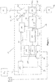
- Figure 1 shows a schematic view of a system comprising a digital output circuit and a closing signature assessment unit according to a first embodiment of the invention.
- a digital output circuit according to a first embodiment of the invention is designated generally by reference numeral 10.
- the digital output circuit 10 includes a switch element 12 which is openable and closeable to selectively permit the flow of current I to an item of equipment 14, e.g. a load 16, which is in-use connected with and controlled by the digital output circuit 10.
- the digital output circuit 10 is also connected in use with a power supply 18 that supplies the aforementioned current I for use by the equipment item 14.
- the switch element 12 is a high-speed high-break contact 20 that is made up of a conventional relay contact 22 which is arranged in parallel with a semiconductor switching element in the form of an Insulated Gate Bipolar Transistor (IGBT) 23.
- IGBT Insulated Gate Bipolar Transistor
- FET Field Effect Transistor
- electromechanical switch other types of switching element such as an electromechanical switch.
- the digital output circuit 10 also includes a current acquisition circuit 24 to measure the current I flowing through the switch element 12.
- the current acquisition circuit 24 includes a current sensor 26 which, in the embodiment shown, takes the form of an impedance 28 connected in series with the switch element 12.
- a current sensor 26 which, in the embodiment shown, takes the form of an impedance 28 connected in series with the switch element 12.
- Other types of current sensor 26 are possible however including, for example, isolated sensing arrangements such as a field-effect sensor, e.g. a hall-effect sensor, or a current transformer. Any current sensor that can handle direct current (DC) and has a wide frequency response so as to be able to measure rapid current transients would be suitable.
- DC direct current
- the aforementioned isolated, or remote, sensing arrangements need not necessarily be integrated within the digital output circuit 10 but instead may provide a measured current I m to the digital output circuit 10.
- the current acquisition circuit 24 also includes a conditioning module 30 to filter and amplify the measured current I m provided by the current sensor 26.
- the conditioning module 30 includes an analogue to digital converter (ADC) 32 to convert the measured current I m into individual measured current samples I s .
- ADC analogue to digital converter
- the ADC 32 converts and scales the measured current I m , and the resolution and sample rate of the ADC 32 is such that there is adequate resolution, both in terms of current and time, in the resulting measured current samples I s that are utilised by further circuits within the digital output circuit 10.
- the digital output circuit 10 shown further includes both an optional primary protection circuit 34 and a condition monitoring circuit 36, each of which is arranged in communication with the current acquisition circuit 24 and, more particularly, each of which is arranged to receive respective measured current samples I s from the current acquisition circuit 24.
- the primary protection circuit 34 is configured to establish a current tripping characteristic that is based on the measured current I m flowing through the switch element 12.
- the primary protection circuit 34 is also configured to initiate opening of the switch element 12 when the current tripping characteristic exceeds a predetermined threshold.
- the primary protection circuit 34 is configured to establish a current-squared time-based current tripping characteristic I 2 T (although other, e.g. arbitrary, tripping characteristics are also possible) and includes the following circuit elements to achieve this: a first buffer 38 to, in use, retain individual measured current samples I s that are provided by the current acquisition circuit 24; and an integrator 40 to sum the current samples I s retained in the first buffer 38 and provide an average of the current samples I s .
- the first buffer 38 is a rotating buffer 42 which is arranged so that when a new measured current sample I s is retained therein, the oldest measured current sample I s in the buffer 42 is overwritten.
- each of the measured current samples I s is squared. This can be done either by the ADC 32 (as is the case in the embodiment shown) or by the rotating buffer 42.
- the measured current samples I s are also obtained at a fixed rate, e.g. as determined by the sampling rate of the ADC 32, so that the average generated by the integrator 40 has a desirable current-squared time-based characteristic which in turn establishes a similarly endowed current tripping characteristic I 2 T.
- the integrator 40 reads the contents of the rotating buffer 42 each time a new measured current sample I s is retained therein and thereafter sums the individual samples to give the integral, i.e. average, over the whole stored sequence of samples. Moreover, because the first buffer 38 is a rotating buffer 42 the average generated by the integrator 40 is a rolling average, such that current tripping characteristic I 2 T similarly tracks a rolling average value.
- Each of the length of the first buffer 38 i.e. the length of the rotating buffer 42, and the rate at which the first buffer 38 retains individual measured current samples I s , is adjustable.
- the rate at which the first buffer 38 retains individual measured current samples I s may be adjusted by altering the sampling rate of the ADC 32.
- the primary protection circuit 34 also includes a threshold comparator 44 to compare the current tripping characteristic I2T with the predetermined threshold.
- the primary protection circuit 34 is additionally configured to initiate closing of the switch element 12, i.e. reset the digital output circuit 10 to its normal operating configuration, when the current tripping characteristic I 2 T falls below the predetermined threshold.
- condition monitoring circuit 36 is configured to record the measured current I s flowing through the switch element 12 as the switch element closes and thereby establish a switch element closing signature, i.e. a distinctive current characteristic indicative of particular performance traits of the equipment item 14 being controlled by the digital output circuit 10.
- condition monitoring circuit 36 is arranged in communication with a closing signature assessment unit 54, which may be a processor, such as a computer or other microprocessor, and which is in any event configured to compare the switch element closing signature with a known reference signature, and to indicate based on the comparison, e.g. when the switch element closing signature deviates to a predetermined extent from the reference signature, that there is a particular problem with the equipment item 14.
- a closing signature assessment unit 54 may be a processor, such as a computer or other microprocessor, and which is in any event configured to compare the switch element closing signature with a known reference signature, and to indicate based on the comparison, e.g. when the switch element closing signature deviates to a predetermined extent from the reference signature, that there is a particular problem with the equipment item 14.
- the condition monitoring circuit 36 includes a buffer, in the form of a condition buffer 46, to record the measured current I m flowing through the switch element 12. More particularly, the condition buffer 46 is a fast buffer which records measured current samples I s , i.e. as provided by the current acquisition circuit 24, during the first few milliseconds of operation of the switch element 12 following an instruction for the switch element 12 to close.
- the condition buffer 46 is also configured to transmit recorded measured current samples I r to the closing signature assessment unit 54. Such transmission of the recorded measured current samples may, for example, take place when the condition buffer 46 is full.
- condition buffer 46 is also configured to empty when the switch element 12 is opened again, such that the condition buffer 46 is then able to again carry out the aforementioned condition monitoring functionality.
- the current acquisition circuit 24 also includes a secondary protection circuit (not shown) which is configured to initiate opening of the switch element 12 when the measured current I m flowing through the switch element 12 exceeds a specified limit, e.g. such as might arise in the event of a short circuit fault.
- a secondary protection circuit (not shown) which is configured to initiate opening of the switch element 12 when the measured current I m flowing through the switch element 12 exceeds a specified limit, e.g. such as might arise in the event of a short circuit fault.
- the digital output circuit 10 shown also includes a switch control module 48 which acts upon command signals from each of the current acquisition circuit 24 and the primary protection circuit 34 to open or close the switch element 12, as required.
- the digital output circuit 10 also includes an interface module 50 which establishes communication between the digital output circuit 10 and a higher level controller 52, such as a protection relay controller or a bay control computer.
- the interface module 50 also sends command signals, which it receives from the higher level controller 52, to the switch control module 48 to control opening and closing of the switch element 12 during normal operation of the digital output circuit 10.
- the higher level controller 52 may incorporate the aforementioned closing signature assessment unit 54.
- the digital output circuit 10 operates as follows.
- the switch control module 48 causes selective opening and closing of the switch element 12, i.e. the relay contact 22 and IGBT 23 therein, in response to command signals provided by the interface module 50 which, in turn, receives these from the higher level controller 52.
- This selective opening and closing of the switch element 12 controls the flow of current I from the current source 18 to the equipment item 14, and thereby controls operation of the equipment item 14.
- the current acquisition circuit 24 sends a command signal to the switch control module 48 to initiate opening of the switch element 12. This protects both the switch element 12 and the equipment item 14 being controlled from excess current flow that might otherwise arise and cause damage to one or both of the switch element 12 and the equipment item 14.
- the measured current I m provided by the current sensor 26 is passed to the conditioning module 30 of the current acquisition circuit 24 where it is filtered and amplified, before being sampled by the ADC 32 to create individual measured current samples I s .
- the ADC 32 additionally squares the measured current samples I s ahead of sending them to the primary protection circuit 34.
- the primary protection circuit 34 establishes a rolling current tripping characteristic I 2 T based on the measured current samples I s .
- the primary protection circuit 34 does so by retaining respective measured current samples I s in the first buffer 38 and using the integrator 40 to sum the individual samples to give the integral, i.e. average, over the whole stored sequence of samples.
- the threshold comparator 44 within the primary protection circuit 34 compares the rolling current tripping characteristic I 2 T with the predetermined threshold and initiates opening of the switch element 12, via a command signal sent to the switch control module 48, when the current tripping characteristic I 2 T exceeds the predetermined threshold (which is indicative of a fault).
- the primary protection circuit 34 is able to initiate closing of the switch element 12, via a further command signal sent to the switch control module 48, once the rolling current tripping characteristic I 2 T falls back below the predetermined threshold.
- the primary protection circuit 34 and associated switch element 12 provide a circuit-interruption functionality which is able to protect both the switch element 12, and the equipment item 14 being controlled by the digital output circuit 10, from excess current and the likely associated damage. Moreover such circuit-interruption functionality can be cancelled, i.e. removed, in the event that the associated fault is of a transient nature.
- the squared measured current samples I s generated by the ADC 32 are sent also to the condition monitoring circuit 36.
- the condition buffer 46 of the condition monitoring circuit 36 begins to record a sequence of such squared measured current samples I s when a command signal initiating closure of the switch element 12 is generated and thereby establishes a switch element closing signature.
- This closing signature is transmitted by the condition buffer 46 to the closing signature assessment unit 54, which may or may not form a part of the higher level controller 52.
- the closing signature assessment unit 54 compares the closing signature with a reference signature and identifies a problem with the operation of the equipment item being controlled by the digital output circuit 10 if the closing signature deviates to a predetermined extent from the reference signature.
Landscapes
- Engineering & Computer Science (AREA)
- Power Engineering (AREA)
- Emergency Protection Circuit Devices (AREA)
- Measurement Of Current Or Voltage (AREA)
- Remote Monitoring And Control Of Power-Distribution Networks (AREA)
- Arrangements For Transmission Of Measured Signals (AREA)
Claims (8)
- System, das eine digitale Ausgangsschaltung (10) zur Steuerung eines Ausrüstungsgegenstandes (14, 16) innerhalb eines Energieverteilungsnetzwerks aufweist, wobei die digitale Ausgangsschaltung (10) aufweist:ein Schaltelement (12) das geöffnet und geschlossen werden kann, um den Stromfluss zu einem Ausrüstungsgegenstand, der im Einsatz durch die digitale Ausgangsschaltung (10) gesteuert wird, wahlweise zuzulassen;eine Stromerfassungsschaltung (24) zur Messung des durch das Schaltelement (12) fließenden Stroms; undeine Zustandsüberwachungsschaltung (36), die in Kommunikationsverbindung mit der Stromerfassungsschaltung (24) angeordnet ist, wobei die Zustandsüberwachungsschaltung (30) eingerichtet ist, um den gemessenen Strom (Im), der durch das Schaltelement (12) fließt, wenn das Schaltelement (12) schließt, aufzuzeichnen und dadurch eine Schließsignatur des Schaltelementes zu erstellen,dadurch gekennzeichnet, dass das System ferner aufweist:eine Schließsignaturauswerteeinheit (54), die mit der Zustandsüberwachungsschaltung (36) in Kommunikationsverbindung angeordnet und eingerichtet ist, um die Schließsignatur des Schaltelementes mit einer bekannten Referenzsignatur zu vergleichen und auf der Basis des Vergleiches anzuzeigen, wenn ein bestimmtes Problem mit dem Ausrüstungsgegenstand (14, 16) vorliegt;wobei die Schließsignaturauswerteeinheit (54) eingerichtet ist, um anzuzeigen, dass ein bestimmtes Problem mit dem Ausrüstungsgegenstand (14, 16) vorliegt, wenn die Schließsignatur des Schaltelementes in einem vorbestimmten Maße von der Referenzsignatur abweicht.
- System nach Anspruch 1, wobei die Zustandsüberwachungsschaltung (36) einen Zwischenspeicher (46) enthält, um den gemessenen Strom (Im), der durch das Schaltelement (12) fließt, aufzuzeichnen.
- System nach Anspruch 2, wobei der Zwischenspeicher (46) eingerichtet ist, um aufgezeichnete gemessene Stromabtastwerte (Im) zu der Schließsignaturauswerteeinheit (54) zu übertragen.
- System nach Anspruch 2 oder Anspruch 3, wobei sich der Zwischenspeicher (46) leert, wenn das Schaltelement (12) öffnet.
- System nach einem beliebigen vorhergehenden Anspruch, wobei die Stromerfassungsschaltung (24) einen Stromsensor (26) enthält.
- System nach Anspruch 5, wobei die Stromerfassungsschaltung (24) zusätzlich ein Konditionierungsmodul (30) enthält, um den gemessenen Strom (Im), der durch den Stromsensor (26) geliefert wird, zu filtern und zu verstärken.
- System nach Anspruch 6, wobei das Konditionierungsmodul (30) einen Analog-Digital-Wandler (32) enthält, um den gemessenen Strom (Im) in einzelne gemessene Stromabtastwerte (Is) umzuwandeln.
- System nach einem beliebigen vorhergehenden Anspruch, wobei die Stromerfassungsschaltung (24) eine sekundäre Schutzschaltung (34) enthält, die eingerichtet ist, um ein Öffnen des Schaltelementes (12) auszulösen, wenn der durch das Schaltelement (12) fließende gemessene Strom (Im) einen festgelegten Grenzwert überschreitet.
Applications Claiming Priority (2)
| Application Number | Priority Date | Filing Date | Title |
|---|---|---|---|
| EP15275052 | 2015-02-25 | ||
| PCT/EP2016/053744 WO2016135126A1 (en) | 2015-02-25 | 2016-02-23 | Improvements in or relating to digital output circuits |
Publications (2)
| Publication Number | Publication Date |
|---|---|
| EP3262669A1 EP3262669A1 (de) | 2018-01-03 |
| EP3262669B1 true EP3262669B1 (de) | 2019-10-23 |
Family
ID=52692567
Family Applications (1)
| Application Number | Title | Priority Date | Filing Date |
|---|---|---|---|
| EP16707021.8A Active EP3262669B1 (de) | 2015-02-25 | 2016-02-23 | Verbesserungen an oder im zusammenhang mit digitalen ausgangsschaltungen |
Country Status (8)
| Country | Link |
|---|---|
| US (1) | US10720292B2 (de) |
| EP (1) | EP3262669B1 (de) |
| JP (1) | JP6795509B2 (de) |
| CN (1) | CN107258007B (de) |
| BR (1) | BR112017018108A2 (de) |
| CA (1) | CA2976299C (de) |
| MX (1) | MX374564B (de) |
| WO (1) | WO2016135126A1 (de) |
Families Citing this family (3)
| Publication number | Priority date | Publication date | Assignee | Title |
|---|---|---|---|---|
| EP3309806B1 (de) | 2016-10-14 | 2020-08-05 | TE Connectivity Germany GmbH | Intelligenter schalter zur automobilanwendung |
| DE102017127983A1 (de) | 2017-11-27 | 2019-05-29 | Beckhoff Automation Gmbh | Sicherungsmodul und feldbussystem mit sicherungsmodul |
| JP7442729B2 (ja) * | 2021-02-17 | 2024-03-04 | 三菱電機株式会社 | 直流電源装置、モータ駆動装置、及び冷凍サイクル適用機器 |
Family Cites Families (14)
| Publication number | Priority date | Publication date | Assignee | Title |
|---|---|---|---|---|
| US5136458A (en) | 1989-08-31 | 1992-08-04 | Square D Company | Microcomputer based electronic trip system for circuit breakers |
| JP3317986B2 (ja) * | 1992-01-16 | 2002-08-26 | 株式会社日立製作所 | 漏電遮断器 |
| US5629869A (en) * | 1994-04-11 | 1997-05-13 | Abb Power T&D Company | Intelligent circuit breaker providing synchronous switching and condition monitoring |
| US5600527A (en) | 1994-12-22 | 1997-02-04 | Eaton Corporation | Circuit interrupter providing protection and waveform capture for harmonic analysis |
| AUPP192298A0 (en) * | 1998-02-19 | 1998-03-12 | Queensland University Of Technology | Methods and apparatus for monitoring ac circuits |
| US6148263A (en) * | 1998-10-27 | 2000-11-14 | Schlumberger Technology Corporation | Activation of well tools |
| EP1214769A1 (de) * | 1999-09-10 | 2002-06-19 | Intra International AB | Verfahren und system zum selbstlernendes leistungssteuerung |
| DE10029789C1 (de) * | 2000-06-16 | 2001-10-11 | Siemens Ag | Verfahren zum Betrieb eines elektromagnetischen Schaltgeräts und elektromagnetisches Schaltgerät |
| US7177125B2 (en) | 2003-02-12 | 2007-02-13 | Honeywell International Inc. | Arc fault detection for SSPC based electrical power distribution systems |
| US7154381B2 (en) * | 2003-05-23 | 2006-12-26 | Sonos, Inc. | System and method for operating a sensed power device over data wiring |
| DE602006020027D1 (de) | 2005-02-16 | 2011-03-24 | Leach Int Corp | Leistungsverteilungssystem unter verwendung von festkörperleistungsreglern |
| US8031455B2 (en) | 2007-01-05 | 2011-10-04 | American Power Conversion Corporation | System and method for circuit overcurrent protection |
| US8773827B2 (en) * | 2008-02-19 | 2014-07-08 | Simply Automated Incorporated | Intelligent circuit breaker apparatus and methods |
| US8760825B2 (en) * | 2012-06-11 | 2014-06-24 | Schneider Electric USA, Inc. | Wireless branch circuit energy monitoring system |
-
2016
- 2016-02-23 JP JP2017542394A patent/JP6795509B2/ja not_active Expired - Fee Related
- 2016-02-23 WO PCT/EP2016/053744 patent/WO2016135126A1/en not_active Ceased
- 2016-02-23 US US15/553,230 patent/US10720292B2/en active Active
- 2016-02-23 BR BR112017018108A patent/BR112017018108A2/pt not_active IP Right Cessation
- 2016-02-23 EP EP16707021.8A patent/EP3262669B1/de active Active
- 2016-02-23 MX MX2017010931A patent/MX374564B/es active IP Right Grant
- 2016-02-23 CN CN201680012322.5A patent/CN107258007B/zh not_active Expired - Fee Related
- 2016-02-23 CA CA2976299A patent/CA2976299C/en active Active
Non-Patent Citations (1)
| Title |
|---|
| None * |
Also Published As
| Publication number | Publication date |
|---|---|
| JP6795509B2 (ja) | 2020-12-02 |
| WO2016135126A1 (en) | 2016-09-01 |
| MX2017010931A (es) | 2018-01-23 |
| JP2018514173A (ja) | 2018-05-31 |
| US10720292B2 (en) | 2020-07-21 |
| US20180240628A1 (en) | 2018-08-23 |
| CN107258007A (zh) | 2017-10-17 |
| MX374564B (es) | 2025-03-06 |
| CN107258007B (zh) | 2019-10-22 |
| CA2976299A1 (en) | 2016-09-01 |
| BR112017018108A2 (pt) | 2018-04-10 |
| CA2976299C (en) | 2023-09-26 |
| EP3262669A1 (de) | 2018-01-03 |
Similar Documents
| Publication | Publication Date | Title |
|---|---|---|
| EP2149953B1 (de) | Lichtbogenblitzerkennungssystem, -vorrichtung und -verfahren | |
| EP3340262B1 (de) | System und verfahren zur überwachung der kontaktlebensdauer eines schutzschalters | |
| EP2139087B1 (de) | Schutzschalter mit verbesserter Wiederschließungsfunktion | |
| CN87105402A (zh) | 带有触头损耗指示器的电路断路器的固体电路跳闸装置 | |
| EP3262669B1 (de) | Verbesserungen an oder im zusammenhang mit digitalen ausgangsschaltungen | |
| EP3073281A1 (de) | Elektronischer schutzschalter | |
| JP5317724B2 (ja) | 開閉器一括遠隔監視方法、開閉器一括遠隔監視システム | |
| KR20150128124A (ko) | 과전류 계전기 | |
| US20190094292A1 (en) | Secure traveling wave distance protection in an electric power delivery system | |
| CN108270206A (zh) | 一种防越级跳闸保护方法和装置 | |
| US6407897B1 (en) | Network protector with diagnostics | |
| KR100961186B1 (ko) | 배전계통에 초전도 전류제한기 적용시 새로운 보호협조방법 | |
| CN207663016U (zh) | 交流滤波器高压断路器分合闸时间在线监测系统 | |
| EP2180491B1 (de) | Gasisoliertes Schutzschaltersystem und Verfahren zur Überwachung eines gasisolierten Schutzschalters | |
| JP2011171178A (ja) | 遮断器監視装置、遮断器監視装置の投入検出方法 | |
| EP3699606B1 (de) | Schutzschaltung für einen mittelspannungs- oder hochspannungstransformator | |
| JP5468461B2 (ja) | 遮断器監視装置および遮断器監視制御システム | |
| EP3035360B1 (de) | Verbesserungen an oder im Zusammenhang mit Stromkreisunterbrechungsvorrichtungen | |
| US20250105616A1 (en) | Switching device and method for protecting an electrical load against overcurrent | |
| CN101601112A (zh) | 保护装置及其操作方法 | |
| JPH09166651A (ja) | 電力用オシロ装置 | |
| CN110366765B (zh) | 断路器 | |
| JP4253310B2 (ja) | 受配電設備を監視する中央監視装置、及びその監視記録方法 | |
| Apostolov et al. | Event driven maintenance based on protective relays data | |
| JP2592909B2 (ja) | 電力用遮断器の制御信号検出装置 |
Legal Events
| Date | Code | Title | Description |
|---|---|---|---|
| STAA | Information on the status of an ep patent application or granted ep patent |
Free format text: STATUS: THE INTERNATIONAL PUBLICATION HAS BEEN MADE |
|
| PUAI | Public reference made under article 153(3) epc to a published international application that has entered the european phase |
Free format text: ORIGINAL CODE: 0009012 |
|
| STAA | Information on the status of an ep patent application or granted ep patent |
Free format text: STATUS: REQUEST FOR EXAMINATION WAS MADE |
|
| 17P | Request for examination filed |
Effective date: 20170925 |
|
| AK | Designated contracting states |
Kind code of ref document: A1 Designated state(s): AL AT BE BG CH CY CZ DE DK EE ES FI FR GB GR HR HU IE IS IT LI LT LU LV MC MK MT NL NO PL PT RO RS SE SI SK SM TR |
|
| AX | Request for extension of the european patent |
Extension state: BA ME |
|
| DAV | Request for validation of the european patent (deleted) | ||
| DAX | Request for extension of the european patent (deleted) | ||
| STAA | Information on the status of an ep patent application or granted ep patent |
Free format text: STATUS: EXAMINATION IS IN PROGRESS |
|
| 17Q | First examination report despatched |
Effective date: 20180829 |
|
| GRAP | Despatch of communication of intention to grant a patent |
Free format text: ORIGINAL CODE: EPIDOSNIGR1 |
|
| STAA | Information on the status of an ep patent application or granted ep patent |
Free format text: STATUS: GRANT OF PATENT IS INTENDED |
|
| INTG | Intention to grant announced |
Effective date: 20190506 |
|
| GRAS | Grant fee paid |
Free format text: ORIGINAL CODE: EPIDOSNIGR3 |
|
| GRAJ | Information related to disapproval of communication of intention to grant by the applicant or resumption of examination proceedings by the epo deleted |
Free format text: ORIGINAL CODE: EPIDOSDIGR1 |
|
| GRAL | Information related to payment of fee for publishing/printing deleted |
Free format text: ORIGINAL CODE: EPIDOSDIGR3 |
|
| STAA | Information on the status of an ep patent application or granted ep patent |
Free format text: STATUS: EXAMINATION IS IN PROGRESS |
|
| GRAR | Information related to intention to grant a patent recorded |
Free format text: ORIGINAL CODE: EPIDOSNIGR71 |
|
| STAA | Information on the status of an ep patent application or granted ep patent |
Free format text: STATUS: GRANT OF PATENT IS INTENDED |
|
| GRAA | (expected) grant |
Free format text: ORIGINAL CODE: 0009210 |
|
| STAA | Information on the status of an ep patent application or granted ep patent |
Free format text: STATUS: THE PATENT HAS BEEN GRANTED |
|
| INTC | Intention to grant announced (deleted) | ||
| AK | Designated contracting states |
Kind code of ref document: B1 Designated state(s): AL AT BE BG CH CY CZ DE DK EE ES FI FR GB GR HR HU IE IS IT LI LT LU LV MC MK MT NL NO PL PT RO RS SE SI SK SM TR |
|
| INTG | Intention to grant announced |
Effective date: 20190916 |
|
| REG | Reference to a national code |
Ref country code: GB Ref legal event code: FG4D |
|
| REG | Reference to a national code |
Ref country code: CH Ref legal event code: EP |
|
| REG | Reference to a national code |
Ref country code: IE Ref legal event code: FG4D |
|
| REG | Reference to a national code |
Ref country code: DE Ref legal event code: R096 Ref document number: 602016022881 Country of ref document: DE |
|
| REG | Reference to a national code |
Ref country code: AT Ref legal event code: REF Ref document number: 1194619 Country of ref document: AT Kind code of ref document: T Effective date: 20191115 |
|
| REG | Reference to a national code |
Ref country code: SE Ref legal event code: TRGR |
|
| REG | Reference to a national code |
Ref country code: NL Ref legal event code: MP Effective date: 20191023 |
|
| REG | Reference to a national code |
Ref country code: LT Ref legal event code: MG4D |
|
| PG25 | Lapsed in a contracting state [announced via postgrant information from national office to epo] |
Ref country code: FI Free format text: LAPSE BECAUSE OF FAILURE TO SUBMIT A TRANSLATION OF THE DESCRIPTION OR TO PAY THE FEE WITHIN THE PRESCRIBED TIME-LIMIT Effective date: 20191023 Ref country code: PT Free format text: LAPSE BECAUSE OF FAILURE TO SUBMIT A TRANSLATION OF THE DESCRIPTION OR TO PAY THE FEE WITHIN THE PRESCRIBED TIME-LIMIT Effective date: 20200224 Ref country code: BG Free format text: LAPSE BECAUSE OF FAILURE TO SUBMIT A TRANSLATION OF THE DESCRIPTION OR TO PAY THE FEE WITHIN THE PRESCRIBED TIME-LIMIT Effective date: 20200123 Ref country code: GR Free format text: LAPSE BECAUSE OF FAILURE TO SUBMIT A TRANSLATION OF THE DESCRIPTION OR TO PAY THE FEE WITHIN THE PRESCRIBED TIME-LIMIT Effective date: 20200124 Ref country code: PL Free format text: LAPSE BECAUSE OF FAILURE TO SUBMIT A TRANSLATION OF THE DESCRIPTION OR TO PAY THE FEE WITHIN THE PRESCRIBED TIME-LIMIT Effective date: 20191023 Ref country code: NO Free format text: LAPSE BECAUSE OF FAILURE TO SUBMIT A TRANSLATION OF THE DESCRIPTION OR TO PAY THE FEE WITHIN THE PRESCRIBED TIME-LIMIT Effective date: 20200123 Ref country code: LV Free format text: LAPSE BECAUSE OF FAILURE TO SUBMIT A TRANSLATION OF THE DESCRIPTION OR TO PAY THE FEE WITHIN THE PRESCRIBED TIME-LIMIT Effective date: 20191023 Ref country code: LT Free format text: LAPSE BECAUSE OF FAILURE TO SUBMIT A TRANSLATION OF THE DESCRIPTION OR TO PAY THE FEE WITHIN THE PRESCRIBED TIME-LIMIT Effective date: 20191023 Ref country code: NL Free format text: LAPSE BECAUSE OF FAILURE TO SUBMIT A TRANSLATION OF THE DESCRIPTION OR TO PAY THE FEE WITHIN THE PRESCRIBED TIME-LIMIT Effective date: 20191023 |
|
| PG25 | Lapsed in a contracting state [announced via postgrant information from national office to epo] |
Ref country code: RS Free format text: LAPSE BECAUSE OF FAILURE TO SUBMIT A TRANSLATION OF THE DESCRIPTION OR TO PAY THE FEE WITHIN THE PRESCRIBED TIME-LIMIT Effective date: 20191023 Ref country code: HR Free format text: LAPSE BECAUSE OF FAILURE TO SUBMIT A TRANSLATION OF THE DESCRIPTION OR TO PAY THE FEE WITHIN THE PRESCRIBED TIME-LIMIT Effective date: 20191023 Ref country code: IS Free format text: LAPSE BECAUSE OF FAILURE TO SUBMIT A TRANSLATION OF THE DESCRIPTION OR TO PAY THE FEE WITHIN THE PRESCRIBED TIME-LIMIT Effective date: 20200224 |
|
| PG25 | Lapsed in a contracting state [announced via postgrant information from national office to epo] |
Ref country code: AL Free format text: LAPSE BECAUSE OF FAILURE TO SUBMIT A TRANSLATION OF THE DESCRIPTION OR TO PAY THE FEE WITHIN THE PRESCRIBED TIME-LIMIT Effective date: 20191023 |
|
| REG | Reference to a national code |
Ref country code: DE Ref legal event code: R097 Ref document number: 602016022881 Country of ref document: DE |
|
| PG2D | Information on lapse in contracting state deleted |
Ref country code: IS |
|
| PG25 | Lapsed in a contracting state [announced via postgrant information from national office to epo] |
Ref country code: DK Free format text: LAPSE BECAUSE OF FAILURE TO SUBMIT A TRANSLATION OF THE DESCRIPTION OR TO PAY THE FEE WITHIN THE PRESCRIBED TIME-LIMIT Effective date: 20191023 Ref country code: ES Free format text: LAPSE BECAUSE OF FAILURE TO SUBMIT A TRANSLATION OF THE DESCRIPTION OR TO PAY THE FEE WITHIN THE PRESCRIBED TIME-LIMIT Effective date: 20191023 Ref country code: EE Free format text: LAPSE BECAUSE OF FAILURE TO SUBMIT A TRANSLATION OF THE DESCRIPTION OR TO PAY THE FEE WITHIN THE PRESCRIBED TIME-LIMIT Effective date: 20191023 Ref country code: RO Free format text: LAPSE BECAUSE OF FAILURE TO SUBMIT A TRANSLATION OF THE DESCRIPTION OR TO PAY THE FEE WITHIN THE PRESCRIBED TIME-LIMIT Effective date: 20191023 Ref country code: CZ Free format text: LAPSE BECAUSE OF FAILURE TO SUBMIT A TRANSLATION OF THE DESCRIPTION OR TO PAY THE FEE WITHIN THE PRESCRIBED TIME-LIMIT Effective date: 20191023 Ref country code: IS Free format text: LAPSE BECAUSE OF FAILURE TO SUBMIT A TRANSLATION OF THE DESCRIPTION OR TO PAY THE FEE WITHIN THE PRESCRIBED TIME-LIMIT Effective date: 20200223 |
|
| REG | Reference to a national code |
Ref country code: AT Ref legal event code: MK05 Ref document number: 1194619 Country of ref document: AT Kind code of ref document: T Effective date: 20191023 |
|
| PLBE | No opposition filed within time limit |
Free format text: ORIGINAL CODE: 0009261 |
|
| STAA | Information on the status of an ep patent application or granted ep patent |
Free format text: STATUS: NO OPPOSITION FILED WITHIN TIME LIMIT |
|
| PG25 | Lapsed in a contracting state [announced via postgrant information from national office to epo] |
Ref country code: IT Free format text: LAPSE BECAUSE OF FAILURE TO SUBMIT A TRANSLATION OF THE DESCRIPTION OR TO PAY THE FEE WITHIN THE PRESCRIBED TIME-LIMIT Effective date: 20191023 Ref country code: SM Free format text: LAPSE BECAUSE OF FAILURE TO SUBMIT A TRANSLATION OF THE DESCRIPTION OR TO PAY THE FEE WITHIN THE PRESCRIBED TIME-LIMIT Effective date: 20191023 Ref country code: SK Free format text: LAPSE BECAUSE OF FAILURE TO SUBMIT A TRANSLATION OF THE DESCRIPTION OR TO PAY THE FEE WITHIN THE PRESCRIBED TIME-LIMIT Effective date: 20191023 |
|
| 26N | No opposition filed |
Effective date: 20200724 |
|
| REG | Reference to a national code |
Ref country code: CH Ref legal event code: PL |
|
| REG | Reference to a national code |
Ref country code: BE Ref legal event code: MM Effective date: 20200229 |
|
| PG25 | Lapsed in a contracting state [announced via postgrant information from national office to epo] |
Ref country code: LU Free format text: LAPSE BECAUSE OF NON-PAYMENT OF DUE FEES Effective date: 20200223 Ref country code: MC Free format text: LAPSE BECAUSE OF FAILURE TO SUBMIT A TRANSLATION OF THE DESCRIPTION OR TO PAY THE FEE WITHIN THE PRESCRIBED TIME-LIMIT Effective date: 20191023 |
|
| PG25 | Lapsed in a contracting state [announced via postgrant information from national office to epo] |
Ref country code: AT Free format text: LAPSE BECAUSE OF FAILURE TO SUBMIT A TRANSLATION OF THE DESCRIPTION OR TO PAY THE FEE WITHIN THE PRESCRIBED TIME-LIMIT Effective date: 20191023 Ref country code: LI Free format text: LAPSE BECAUSE OF NON-PAYMENT OF DUE FEES Effective date: 20200229 Ref country code: CH Free format text: LAPSE BECAUSE OF NON-PAYMENT OF DUE FEES Effective date: 20200229 Ref country code: SI Free format text: LAPSE BECAUSE OF FAILURE TO SUBMIT A TRANSLATION OF THE DESCRIPTION OR TO PAY THE FEE WITHIN THE PRESCRIBED TIME-LIMIT Effective date: 20191023 |
|
| PG25 | Lapsed in a contracting state [announced via postgrant information from national office to epo] |
Ref country code: IE Free format text: LAPSE BECAUSE OF NON-PAYMENT OF DUE FEES Effective date: 20200223 |
|
| PG25 | Lapsed in a contracting state [announced via postgrant information from national office to epo] |
Ref country code: BE Free format text: LAPSE BECAUSE OF NON-PAYMENT OF DUE FEES Effective date: 20200229 |
|
| PG25 | Lapsed in a contracting state [announced via postgrant information from national office to epo] |
Ref country code: TR Free format text: LAPSE BECAUSE OF FAILURE TO SUBMIT A TRANSLATION OF THE DESCRIPTION OR TO PAY THE FEE WITHIN THE PRESCRIBED TIME-LIMIT Effective date: 20191023 Ref country code: MT Free format text: LAPSE BECAUSE OF FAILURE TO SUBMIT A TRANSLATION OF THE DESCRIPTION OR TO PAY THE FEE WITHIN THE PRESCRIBED TIME-LIMIT Effective date: 20191023 Ref country code: CY Free format text: LAPSE BECAUSE OF FAILURE TO SUBMIT A TRANSLATION OF THE DESCRIPTION OR TO PAY THE FEE WITHIN THE PRESCRIBED TIME-LIMIT Effective date: 20191023 |
|
| PG25 | Lapsed in a contracting state [announced via postgrant information from national office to epo] |
Ref country code: MK Free format text: LAPSE BECAUSE OF FAILURE TO SUBMIT A TRANSLATION OF THE DESCRIPTION OR TO PAY THE FEE WITHIN THE PRESCRIBED TIME-LIMIT Effective date: 20191023 |
|
| P01 | Opt-out of the competence of the unified patent court (upc) registered |
Effective date: 20230522 |
|
| PGFP | Annual fee paid to national office [announced via postgrant information from national office to epo] |
Ref country code: SE Payment date: 20260121 Year of fee payment: 11 |
|
| PGFP | Annual fee paid to national office [announced via postgrant information from national office to epo] |
Ref country code: GB Payment date: 20260121 Year of fee payment: 11 |
|
| PGFP | Annual fee paid to national office [announced via postgrant information from national office to epo] |
Ref country code: DE Payment date: 20260121 Year of fee payment: 11 |
|
| PGFP | Annual fee paid to national office [announced via postgrant information from national office to epo] |
Ref country code: FR Payment date: 20260121 Year of fee payment: 11 |