EP2180491B1 - Gasisoliertes Schutzschaltersystem und Verfahren zur Überwachung eines gasisolierten Schutzschalters - Google Patents
Gasisoliertes Schutzschaltersystem und Verfahren zur Überwachung eines gasisolierten Schutzschalters Download PDFInfo
- Publication number
- EP2180491B1 EP2180491B1 EP09013346.3A EP09013346A EP2180491B1 EP 2180491 B1 EP2180491 B1 EP 2180491B1 EP 09013346 A EP09013346 A EP 09013346A EP 2180491 B1 EP2180491 B1 EP 2180491B1
- Authority
- EP
- European Patent Office
- Prior art keywords
- contact
- main
- resistor
- temperature
- signal
- Prior art date
- Legal status (The legal status is an assumption and is not a legal conclusion. Google has not performed a legal analysis and makes no representation as to the accuracy of the status listed.)
- Not-in-force
Links
- 238000000034 method Methods 0.000 title claims description 7
- 238000012544 monitoring process Methods 0.000 title claims description 6
- 238000005259 measurement Methods 0.000 claims description 16
- 230000001681 protective effect Effects 0.000 claims description 8
- 238000009529 body temperature measurement Methods 0.000 claims description 4
- 239000002184 metal Substances 0.000 description 7
- 230000005540 biological transmission Effects 0.000 description 5
- 238000010586 diagram Methods 0.000 description 4
- 238000006243 chemical reaction Methods 0.000 description 3
- 238000001816 cooling Methods 0.000 description 1
- 230000010354 integration Effects 0.000 description 1
- 238000012545 processing Methods 0.000 description 1
- 238000012546 transfer Methods 0.000 description 1
Images

Classifications
-
- H—ELECTRICITY
- H01—ELECTRIC ELEMENTS
- H01H—ELECTRIC SWITCHES; RELAYS; SELECTORS; EMERGENCY PROTECTIVE DEVICES
- H01H33/00—High-tension or heavy-current switches with arc-extinguishing or arc-preventing means
- H01H33/02—Details
- H01H33/04—Means for extinguishing or preventing arc between current-carrying parts
- H01H33/16—Impedances connected with contacts
- H01H33/168—Impedances connected with contacts the impedance being inserted both while closing and while opening the switch
Definitions
- the present invention relates to a gas insulated circuit breaker system with a resistor and a gas insulated circuit breaker monitoring method and, more particularly, to a technique that takes temperature rise of the resistor into consideration so as to improve operation performance of a gas insulated circuit breaker with resistor.
- a resistor/contact connected member obtained by serially connecting a resistor contact and a resistor is connected in parallel to a main contact in order to suppress a surge voltage generated at the contact closing/opening time.
- the resistor contact is closed before the closing of the main contact, and at the contact opening time, the resister contact is opened after the opening of the main contact.
- a large energy is injected to the resistor to heat the resistor up to 200 °C to 300 °C.
- an over-current may flow through the resistor. If the resistor breaks down due to the flowing of over-current, a thermo-runaway may occur (refer to, e.g., Japanese Patent Application Laid-open Publication No. 05-041302 ).
- FR 2 896 335 A1 discloses a gas insulated circuit breaker system according to the preamble of claim 1.
- the present invention has been made to solve the above mentioned problem, and an object thereof is to estimate or predict the temperature of a circuit-breaker resistor or a wait time required until the subsequent operation becomes ready without additionally providing a sensor for directly measuring the temperature of the resistor so as to improve operation of a gas insulated circuit breaker with resistor.
- a gas insulated circuit breaker system comprising: a container that encapsulates an insulating gas; a main contact that is contained in the container and opens and closes a main circuit; a resistor contact that is contained in the container, connected in parallel to the main contact, and configured to be opened after elapse of a predetermined time after the main contact is opened and to be closed at a predetermined time before the main contact is closed; a resistor that is contained in the container, serially connected to the resistor contact, and connected in parallel to the main contact together with the resistor contact; a temperature sensor that measures a temperature of surrounding of the resistor; and a temperature estimation section that estimates a temperature of the resistor based on a contact signal representing a timing of opening and closing operation of the main contact, a current signal representing a current flowing through the main circuit, and a temperature signal output from the temperature sensor.
- a gas insulated circuit breaker monitoring method for monitoring a gas insulated circuit breaker comprising: a container that encapsulates an insulating gas; a main contact that is contained in the container and opens and closes a main circuit; a resistor contact that is contained in the container, connected in parallel to the main contact, and configured to be opened after elapse of a predetermined time after the main contact is opened and to be closed at a predetermined time before the main contact is closed; and a resistor that is contained in the container, serially connected to the resistor contact, and connected in parallel to the main contact together with the resistor contact, the method comprising: a contact signal input step of inputting a contact signal representing a timing of opening and closing operation of the main contact; a main circuit current input step of inputting a current signal representing a current flowing through the main circuit; a temperature measurement step of measuring a temperature of surrounding of the resistor; a temperature signal input step of inputting a temperature signal obtained in the temperature measurement step; and
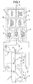
- FIG. 1 is a block diagram schematically showing a first embodiment of a gas insulated circuit breaker system according to the present invention.
- FIG. 2 is a time chart at the main circuit closing time in the first embodiment, in which line “A” shows a main circuit current, line “B” shows an operation of an auxiliary switch, and line “C” shows an operation of a main contact.
- the gas insulated circuit breaker 1 with resistor includes main contacts 2 disposed in a metal container 15 in which an insulating gas is encapsulated and connected in a main circuit 6.
- main contacts 2 disposed in a metal container 15 in which an insulating gas is encapsulated and connected in a main circuit 6.
- two main contacts are serially connected to each other.
- resistor/contact connected members 30 are connected in parallel.
- Each of the resistor/contact connected members 30 is constructed by serially connecting a resistor 4 and a resistor contact 3.
- the two pairs of the main contacts 2 and resistor/contact connected members 30 are contained in one common metal container 15.
- a temperature sensor 16 is attached to the metal container 15.
- a main circuit current measurement circuit 7 including a current transformer 31 is provided in the main circuit 6 at the outside of the metallic container 15.
- the main circuit current measurement circuit 7 is connected to a not shown protective relay and the like.
- an auxiliary current transformer 8 is provided in the main circuit current measurement circuit 7 to constitute an auxiliary current measurement circuit 32.
- a signal processor 9 is provided near the gas insulated circuit breaker 1 with resistor.
- the signal processor 9 includes a contact signal input section 10, a current signal input section 11, a temperature signal input section 12, and calculation/storage section 13.
- the calculation/storage section 13 includes a temperature estimation section 20, a wait time calculation section 21, and a recording section 22.
- An auxiliary switch 5 is opened and closed in conjunction with the main contact 2, and a contact signal from the auxiliary switch 5 is input to the contact signal input section 10.
- the input signal is converted into a digital signal by the contact signal input section 10 and then input to the calculation/storage section 13.
- a main circuit current signal output from the auxiliary current transformer 8 is input, via the auxiliary current measurement circuit 32, to the current signal input section 11 where the input signal is subjected to analog/digital conversion and then input to the calculation/storage section 13.
- a signal from the temperature sensor 16 is input to the temperature signal input section 12 where the input signal is subjected to analog/digital conversion and input to the calculation/storage section 13.
- the calculation/storage section 13 is connected to the higher level system by a transmission line 14.
- FIG. 2 shows, in the form of a graph, current information recorded in the calculation/storage section 13, operation information of the auxiliary switch 5, and operation information of the main contact 2 in the present embodiment.
- operation of processing of calculating temperature rise of the resistor 4 performed in the gas insulated circuit breaker system with resistor will be described in detail.
- a temperature rise " ⁇ T” of the resistor 4 can be calculated according to the following equation (1).
- ⁇ T ⁇ lr t ⁇ 2 dt ⁇ R / ⁇
- Ir an electric current flowing through the resistor
- R is a resistance value of the resistor
- ⁇ is a specific heat ratio of the resistor.
- FIG. 2 A change in an electric current at the time when a circuit breaker breaks a fault current and a change in a status of the main contact 2 of the circuit breaker are shown in FIG. 2 .
- the calculation/storage section 13 samples the electric current at a predetermined frequency and performs the integration with respect to an electric current after the circuit breaker main contact 2 is opened and separated to cause the electric current to be transferred to the resistor contact 3 (shaded area in FIG. 2 ) according to the equation (1) to thereby calculate the temperature rise ⁇ T of the resistor.
- the opening timing of the main contact 2 is calculated from a signal change in the auxiliary switch 5 of the main contact, and zero point before a current level becomes smaller after the opening timing of the main contact 2 is detected.
- Tr ⁇ 0 Tamb + ⁇ T + ⁇
- Tr ⁇ 0 Tamb + ⁇ T + ⁇
- ⁇ an estimated temperature rise due to the electric current and the direct insolation.
- Tr ⁇ T ⁇ exp - t / ⁇ + Tamb + ⁇
- t is the time length after operation of the circuit breaker
- ⁇ is the cooling time constant of the resistor
- the temperature estimation section 20 of the signal processor 9 can estimate the temperature of the resistor 4 after breaking of a fault current. Further, a wait time required until the subsequent operation becomes ready can be calculated in the wait time calculation section 21. These calculation results are recorded in the recording section 22, allowing the calculated wait time to be notified, via the transmission line 14, to the upper level system that outputs an operation command to the gas insulted circuit breaker 1 with resistor as transmission data.
- a prohibition signal output section 23 that outputs a signal for prohibiting operation for the gas insulated circuit breaker 1 with resistor during the wait time may be optionally provided in the calculation/storage section 13.
- the present embodiment it is possible to estimate the temperature of the resistor without need to directly measure the temperature of the resistor to which a high voltage is applied, i.e., without changing the structure of the circuit breaker. Therefore, determination on the operation for the circuit breaker can be rationalized to thereby increase reliability of the circuit breaker.
- the auxiliary current transformer 8 is provided in the main circuit current measurement circuit 7, and a main circuit current signal output from the auxiliary current transformer 8 is input to the current signal input section 11 via the auxiliary current measurement circuit 32. Therefore, interference from the current signal input section 11 side to the main circuit current measurement circuit 7 is eliminated. Since the main circuit current measurement circuit 7 serves as an important circuit for transmitting main circuit current information to the higher level system, it is important that the main circuit current information to be transmitted to the higher level system is not interfered by the signal processor 9.
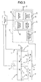
- FIG. 3 is a block diagram schematically showing a second embodiment of the gas insulated circuit breaker system according to the present invention.
- signals of the auxiliary switch 5 and main circuit current measurement circuit 7 are transmitted to a protective relay unit 17.
- the operation timing signal of the main contact 2 and the electric current information of the main circuit 6 are input from the protective relay unit 17, via a transmission line 18, to the calculation/storage section 13 of the signal processor 9.
- the auxiliary current transformer 8 and the auxiliary current measurement circuit 32 need not be provided.
- a contact signal (contact signal of the auxiliary switch 5) representing the timing of opening/closing operation of the main contact 2 and a signal representing the current flowing through the main circuit 6 are converted into digital signals in the protective relay unit 17 and are input, via the transmission line 18, to the calculation/storage section 13 of the signal processor 9 as digital signals.
- an analog/digital conversion function such as the contact signal input section 10 or the current signal input section 11 of the first embodiment need not be provided in the signal processor 9 of the second embodiment.
- the system structure can be simplified.
- the temperature sensor 16 is attached to the metal container 15 that contains the main contact 2 and resistor/contact connected member 30 in the above mentioned embodiments, the temperature sensor 16 may be alternatively attached to another container connected to the metal container 15 or a structure provided near the metal container 15.
Landscapes
- Gas-Insulated Switchgears (AREA)
- Arc-Extinguishing Devices That Are Switches (AREA)
- Circuit Breakers (AREA)
- Keying Circuit Devices (AREA)
- Testing Electric Properties And Detecting Electric Faults (AREA)
Claims (9)
- Gasisolierter Leistungsschaltersystem, das Folgendes umfasst:einen Behälter (15), der ein isolierendes Gas verkapselt;einen Hauptkontakt (2), der in dem Behälter (15) enthalten ist und einen Hauptstromkreis (6) öffnet undschließt;einen Widerstandskontakt (3), der in dem Behälter (15) enthalten ist, mit dem Hauptkontakt (2) parallel geschaltet ist und dafür konfiguriert ist, geöffnet zu werden, nachdem eine vorgegebene Zeit nach dem Öffnen des Hauptkontakts (2) verstrichen ist, und an einem vorgegebenen Zeitpunkt vor dem Schließen des Hauptkontakts (2) geschlossen zu werden;einen Widerstand (4), der in dem Behälter (15) enthalten ist, mit dem Widerstandskontakt (3) in Reihe geschaltet ist und mit dem Hauptkontakt (2) zusammen mit dem Widerstandskontakt (3) parallel geschaltet ist; dadurch gekennzeichnet, dass das gasisolierte Leistungsschaltersystem Folgendes umfasst:einen Temperatursensor (16), der eine Temperatur der Umgebung des Widerstands (4) misst; undeinen Temperaturschätzungsabschnitt (20), der eine Temperatur des Widerstandes (4) auf der Grundlage eines Kontaktsignals schätzt, das einen Zeitpunkt des Öffnungs- und Schließvorgangs des Hauptkontakts (2) darstellt, eines Stromsignals, das einen Strom darstellt, der durch den Hauptstromkreis (6) fließt, und eines Temperaturausgangssignals von dem Temperatursensor (16).
- Gasisoliertes Leistungsschaltersystem nach Anspruch 1,
das des Weiteren Folgendes umfasst:einen Wartezeitberechnungsabschnitt (21), der eineWartezeit, die erforderlich ist, bis ein anschließender Öffnungs- oder Schließvorgang des Hauptkontakts (2) bereit wird, auf der Grundlage eines Ausgangssignals des Temperaturschätzungsabschnitts (20) und des Temperatursignals berechnet. - Gasisoliertes Leistungsschaltersystem nach Anspruch 2, das des Weiteren Folgendes umfasst:einen Verbotssignalausgangsabschnitt (23), der an ein übergeordnetes System, das den Öffnungs- undSchließvorgang des Hauptkontakts (2) steuert, ein Betriebsverbotssignal ausgibt, um den Öffnungs- undSchließvorgang des Hauptkontakts (2) während der Wartezeit zu untersagen.
- Gasisoliertes Leistungsschaltersystem nach einem der Ansprüche 1 bis 3, das des Weiteren Folgendes umfasst:einen Hilfsschalter (5), der außerhalb des Behälters (15) angeordnet ist und in Verbindung mit dem Öffnungs- und Schließvorgang des Hauptkontakts (2) geöffnet und geschlossen wird, wobeidas Kontaktsignal ein Signal ist, das einen Zeitpunkt des Öffnungs- und Schließvorgangs des Hilfsschalters darstellt.
- Gasisoliertes Leistungsschaltersystem nach einem der Ansprüche 1 bis 4, wobei
der Temperatursensor (16) an dem Behälter (15) oder an einer mit dem Behälter (15) verbundenen Struktur angebracht ist. - Gasisoliertes Leistungsschaltersystem nach einem der Ansprüche 1 bis 5, wobei
das Kontaktsignal ein Signal ist, das beim Auftreten eines Fehlers, der einen Öffnungsvorgang des Hauptkontakts (2) erfordert, von einem Schutzrelais (17) empfangen wird, das einen Befehl zum Öffnen des Hauptkontakts (2) ausgibt. - Gasisoliertes Leistungsschaltersystem nach einem der Ansprüche 1 bis 6, das des Weiteren Folgendes umfasst:einen Hauptstromkreis-Strommessungsschaltkreis (7),der an den Hauptstromkreis (6) angeschlossen ist,wobei der Hauptstromkreis-Strommessungsschaltkreis (7) mit dem Schutzrelais (17) verbunden ist, das einen Befehl zum Öffnen des Hauptkontakts (2) ausgibt unddafür konfiguriert ist, einen durch den Hauptstromkreis (6) fließenden Strom zu messen; undeinen Hilfsstromtransformator, der an den Hauptstromkreis-Strommessungsschaltkreis (7) angeschlossen ist, wobeidas Stromsignal ein Ausgangssignal des Hilfsstromtransformators ist.
- Gasisoliertes Leistungsschaltersystem nach einem der Ansprüche 1 bis 6, das des Weiteren Folgendes umfasst:einen Hauptstromkreis-Strommessungsschaltkreis (7),der mit dem Hauptstromkreis (6) verbunden ist, wobei der Hauptstromkreis-Strommessungsschaltkreis (7) mit einem Schutzrelais (17) verbunden ist, das einen Befehl zum Öffnen des Hauptkontakts (2) ausgibt unddafür konfiguriert ist, einen durch den Hauptstromkreis (6) fließenden Strom zu messen, wobeidas Stromsignal ein Eingangssignal von dem Schutzrelais (17) ist.
- Überwachungsverfahren für einen gasisolierten Leistungsschalter zum Überwachen eines gasisolierten Leistungsschalters, der Folgendes umfasst:einen Behälter (15), der ein isolierendes Gas verkapselt;einen Hauptkontakt (2), der in dem Behälter (15) enthalten ist und einen Hauptstromkreis (6) öffnet undschließt;einen Widerstandskontakt (3), der in dem Behälter (15) enthalten ist, mit dem Hauptkontakt (2) parallel geschaltet ist und dafür konfiguriert ist, geöffnet zu werden, nachdem eine vorgegebene Zeit nach dem Öffnen des Hauptkontakts (2) verstrichen ist, und an einem vorgegebenen Zeitpunkt vor dem Schließen des Hauptkontakts (2) geschlossen zu werden;einen Widerstand (4), der in dem Behälter (15) enthalten ist, mit dem Widerstandskontakt (3) in Reihe geschaltet ist und mit dem Hauptkontakt (2) zusammen mit dem Widerstandskontakt (3) parallel geschaltet ist;wobei das Verfahren Folgendes umfasst:einen Kontaktsignaleingabeschritt zum Eingeben eines Kontaktsignals, das einen Zeitpunkt des Öffnungs- und Schließvorgangs des Hauptkontakts (2) darstellt;einen Hauptstromkreis-Stromeingabeschritt zum Eingeben eines Stromsignals, das einen durch den Hauptstromkreis (6) fließenden Strom darstellt;einen Temperaturmessungsschritt zum Messen einer Temperatur der Umgebung des Widerstandes (4);einen Temperatursignaleingabeschritt zum Eingeben eines in dem Temperaturmessungsschritt erhaltenen Temperatursignals; undeinen Temperaturschätzungsschritt zum Schätzen der Temperatur des Widerstandes (4) auf der Grundlage des Kontaktsignals, des Stromsignals und des Temperatursignals.
Applications Claiming Priority (1)
| Application Number | Priority Date | Filing Date | Title |
|---|---|---|---|
| JP2008274363A JP5166204B2 (ja) | 2008-10-24 | 2008-10-24 | ガス絶縁遮断器システムおよびガス絶縁遮断器監視方法 |
Publications (2)
| Publication Number | Publication Date |
|---|---|
| EP2180491A1 EP2180491A1 (de) | 2010-04-28 |
| EP2180491B1 true EP2180491B1 (de) | 2014-06-18 |
Family
ID=41508261
Family Applications (1)
| Application Number | Title | Priority Date | Filing Date |
|---|---|---|---|
| EP09013346.3A Not-in-force EP2180491B1 (de) | 2008-10-24 | 2009-10-22 | Gasisoliertes Schutzschaltersystem und Verfahren zur Überwachung eines gasisolierten Schutzschalters |
Country Status (4)
| Country | Link |
|---|---|
| US (1) | US8199445B2 (de) |
| EP (1) | EP2180491B1 (de) |
| JP (1) | JP5166204B2 (de) |
| CN (1) | CN101728783B (de) |
Families Citing this family (4)
| Publication number | Priority date | Publication date | Assignee | Title |
|---|---|---|---|---|
| US9362071B2 (en) | 2011-03-02 | 2016-06-07 | Franklin Fueling Systems, Inc. | Gas density monitoring system |
| IN2014DN07676A (de) | 2012-02-20 | 2015-05-15 | Franklin Fueling Systems Inc | |
| EP2700962B1 (de) * | 2012-08-24 | 2018-11-07 | Omicron electronics GmbH | Messung eines Widerstands eines Schaltkontakts eines elektrischen Leistungsschalters |
| CN118336655B (zh) * | 2024-06-12 | 2024-08-30 | 华能澜沧江水电股份有限公司 | 用于接触电阻式大型发电机gcb断路器的保护方法及装置 |
Family Cites Families (23)
| Publication number | Priority date | Publication date | Assignee | Title |
|---|---|---|---|---|
| US3164705A (en) * | 1961-03-01 | 1965-01-05 | Westinghouse Electric Corp | Fluid-blast circuit interrupters with retractable impedance probe |
| DE1191015B (de) * | 1961-06-26 | 1965-04-15 | Asea Ab | Druckluftschalter mit Daempfungswiderstand |
| US3452172A (en) * | 1965-07-12 | 1969-06-24 | Siemens Ag | Current limiting circuit breaker |
| US3538278A (en) * | 1968-06-13 | 1970-11-03 | Gen Electric | High voltage electric circuit breaker |
| US4035692A (en) * | 1975-11-20 | 1977-07-12 | Cutler-Hammer, Inc. | Resistor protection systems |
| US4069406A (en) * | 1975-12-02 | 1978-01-17 | Allis-Chalmers Corporation | Closing resistor switch for gas insulated circuit breaker |
| FR2512267A1 (fr) * | 1981-08-26 | 1983-03-04 | Alsthom Atlantique | Disjoncteur a gaz comprime muni de resistances d'ouverture et de fermeture |
| JPS6155829A (ja) * | 1984-08-28 | 1986-03-20 | 株式会社東芝 | しや断器 |
| JPH0244816U (de) * | 1988-09-22 | 1990-03-28 | ||
| FR2674064B1 (fr) * | 1991-03-13 | 1993-06-04 | Alsthom Gec | Dispositif de varistance et de resistance pour la chambre de coupure d'un disjoncteur. |
| JPH05101907A (ja) * | 1991-03-30 | 1993-04-23 | Toshiba Corp | 電力用遮断器および電力用抵抗体 |
| JPH0541302A (ja) | 1991-08-06 | 1993-02-19 | Hitachi Ltd | バルク型直線抵抗体およびその製造方法 |
| JPH06141460A (ja) * | 1992-10-27 | 1994-05-20 | Central Japan Railway Co | 保護継電装置 |
| DE19547098A1 (de) * | 1995-12-16 | 1997-06-19 | Asea Brown Boveri | Leistungsschalter mit einem Einschaltwiderstand |
| JP3887438B2 (ja) * | 1996-11-01 | 2007-02-28 | 株式会社東芝 | 変電設備 |
| US6072673A (en) * | 1998-11-19 | 2000-06-06 | Square D Company | Medium to high voltage load circuit interrupters including metal resistors having a positive temperature coefficient of resistivity (PTC elements) |
| AU2003219535A1 (en) * | 2003-03-14 | 2004-09-30 | Magnetek S.P.A. | Electronic circuit breaker |
| JP4108614B2 (ja) * | 2004-01-13 | 2008-06-25 | 三菱電機株式会社 | 位相制御開閉装置 |
| CN2701141Y (zh) * | 2004-05-31 | 2005-05-18 | 曹志伟 | 断路器合闸、分闸线圈的保护装置 |
| JP4724003B2 (ja) * | 2006-01-10 | 2011-07-13 | 株式会社日本Aeパワーシステムズ | ガス絶縁開閉装置 |
| FR2896335B1 (fr) * | 2006-01-17 | 2008-11-14 | Areva T & D Sa | Disjoncteur de generateur avec resistance inseree |
| US7869170B2 (en) * | 2006-07-14 | 2011-01-11 | Susan Jean Walker Colsch | Method and system for time synchronized trip algorithms for breaker self protection |
| JP5116607B2 (ja) * | 2008-08-18 | 2013-01-09 | 株式会社日立製作所 | ガス遮断器 |
-
2008
- 2008-10-24 JP JP2008274363A patent/JP5166204B2/ja not_active Expired - Fee Related
-
2009
- 2009-10-16 US US12/580,527 patent/US8199445B2/en not_active Expired - Fee Related
- 2009-10-20 CN CN200910179467.6A patent/CN101728783B/zh not_active Expired - Fee Related
- 2009-10-22 EP EP09013346.3A patent/EP2180491B1/de not_active Not-in-force
Also Published As
| Publication number | Publication date |
|---|---|
| CN101728783A (zh) | 2010-06-09 |
| US20100102036A1 (en) | 2010-04-29 |
| JP5166204B2 (ja) | 2013-03-21 |
| CN101728783B (zh) | 2013-03-20 |
| US8199445B2 (en) | 2012-06-12 |
| EP2180491A1 (de) | 2010-04-28 |
| JP2010102995A (ja) | 2010-05-06 |
Similar Documents
| Publication | Publication Date | Title |
|---|---|---|
| EP2139087B1 (de) | Schutzschalter mit verbesserter Wiederschließungsfunktion | |
| EP3255443A1 (de) | Verfahren zur schätzung der integrität eines leistungssystems | |
| EP2180491B1 (de) | Gasisoliertes Schutzschaltersystem und Verfahren zur Überwachung eines gasisolierten Schutzschalters | |
| CN104459524B (zh) | 辅助单元、含断路器和辅助单元的电力系统及确定断路器断开原因的方法 | |
| CN103797674B (zh) | 用于保护用电器的装置和方法 | |
| US6442493B1 (en) | Method of detecting a fault in a monitored section of an electric transmission line using distance protection techniques | |
| US11757282B2 (en) | Method and device for controlling at least one circuit breaker of a power system | |
| US20160301199A1 (en) | Power switching control apparatus and switching control method therefor | |
| CN115078993A (zh) | 带有绝缘预警功能的高压电机绝缘检测系统及方法 | |
| US20090122454A1 (en) | Augmentation of ambient temperature and free convection effects in thermal circuit breaker trip curve approximations | |
| US20110098951A1 (en) | Arrangement and method for generating a fault signal | |
| US9325165B2 (en) | Device and method for protecting a consumer | |
| CN207663016U (zh) | 交流滤波器高压断路器分合闸时间在线监测系统 | |
| EP3262669B1 (de) | Verbesserungen an oder im zusammenhang mit digitalen ausgangsschaltungen | |
| EP3795966B1 (de) | Schutzschalter und verfahren zur schätzung der temperatur einer sammelschiene in einem schutzschalter | |
| KR101089316B1 (ko) | 가스절연개폐장치의 차단부 동작 특성 측정 장치 및 방법 | |
| JP2000207982A (ja) | 遮断器の開閉制御装置 | |
| US9520707B2 (en) | Device for protecting a user | |
| KR102368705B1 (ko) | 초전도한류기 동작 판단 시스템 및 그 방법 | |
| US20250105616A1 (en) | Switching device and method for protecting an electrical load against overcurrent | |
| RU2335837C1 (ru) | Устройство защиты автоматического выключателя от перегрузок | |
| CN121477054A (zh) | 高频变压器实时寿命预测与预警方法、系统、设备及介质 | |
| RU67346U1 (ru) | Устройство защиты автоматического выключателя от перегрузок |
Legal Events
| Date | Code | Title | Description |
|---|---|---|---|
| PUAI | Public reference made under article 153(3) epc to a published international application that has entered the european phase |
Free format text: ORIGINAL CODE: 0009012 |
|
| 17P | Request for examination filed |
Effective date: 20091022 |
|
| AK | Designated contracting states |
Kind code of ref document: A1 Designated state(s): AT BE BG CH CY CZ DE DK EE ES FI FR GB GR HR HU IE IS IT LI LT LU LV MC MK MT NL NO PL PT RO SE SI SK SM TR |
|
| AX | Request for extension of the european patent |
Extension state: AL BA RS |
|
| GRAP | Despatch of communication of intention to grant a patent |
Free format text: ORIGINAL CODE: EPIDOSNIGR1 |
|
| RIC1 | Information provided on ipc code assigned before grant |
Ipc: H01H 33/16 20060101AFI20140113BHEP |
|
| INTG | Intention to grant announced |
Effective date: 20140203 |
|
| GRAS | Grant fee paid |
Free format text: ORIGINAL CODE: EPIDOSNIGR3 |
|
| GRAA | (expected) grant |
Free format text: ORIGINAL CODE: 0009210 |
|
| AK | Designated contracting states |
Kind code of ref document: B1 Designated state(s): AT BE BG CH CY CZ DE DK EE ES FI FR GB GR HR HU IE IS IT LI LT LU LV MC MK MT NL NO PL PT RO SE SI SK SM TR |
|
| REG | Reference to a national code |
Ref country code: GB Ref legal event code: FG4D |
|
| REG | Reference to a national code |
Ref country code: CH Ref legal event code: EP |
|
| REG | Reference to a national code |
Ref country code: AT Ref legal event code: REF Ref document number: 673771 Country of ref document: AT Kind code of ref document: T Effective date: 20140715 |
|
| REG | Reference to a national code |
Ref country code: IE Ref legal event code: FG4D |
|
| REG | Reference to a national code |
Ref country code: DE Ref legal event code: R096 Ref document number: 602009024698 Country of ref document: DE Effective date: 20140731 |
|
| PG25 | Lapsed in a contracting state [announced via postgrant information from national office to epo] |
Ref country code: LT Free format text: LAPSE BECAUSE OF FAILURE TO SUBMIT A TRANSLATION OF THE DESCRIPTION OR TO PAY THE FEE WITHIN THE PRESCRIBED TIME-LIMIT Effective date: 20140618 Ref country code: CY Free format text: LAPSE BECAUSE OF FAILURE TO SUBMIT A TRANSLATION OF THE DESCRIPTION OR TO PAY THE FEE WITHIN THE PRESCRIBED TIME-LIMIT Effective date: 20140618 Ref country code: FI Free format text: LAPSE BECAUSE OF FAILURE TO SUBMIT A TRANSLATION OF THE DESCRIPTION OR TO PAY THE FEE WITHIN THE PRESCRIBED TIME-LIMIT Effective date: 20140618 Ref country code: GR Free format text: LAPSE BECAUSE OF FAILURE TO SUBMIT A TRANSLATION OF THE DESCRIPTION OR TO PAY THE FEE WITHIN THE PRESCRIBED TIME-LIMIT Effective date: 20140919 Ref country code: NO Free format text: LAPSE BECAUSE OF FAILURE TO SUBMIT A TRANSLATION OF THE DESCRIPTION OR TO PAY THE FEE WITHIN THE PRESCRIBED TIME-LIMIT Effective date: 20140918 |
|
| REG | Reference to a national code |
Ref country code: NL Ref legal event code: VDEP Effective date: 20140618 |
|
| REG | Reference to a national code |
Ref country code: AT Ref legal event code: MK05 Ref document number: 673771 Country of ref document: AT Kind code of ref document: T Effective date: 20140618 |
|
| REG | Reference to a national code |
Ref country code: LT Ref legal event code: MG4D |
|
| PG25 | Lapsed in a contracting state [announced via postgrant information from national office to epo] |
Ref country code: HR Free format text: LAPSE BECAUSE OF FAILURE TO SUBMIT A TRANSLATION OF THE DESCRIPTION OR TO PAY THE FEE WITHIN THE PRESCRIBED TIME-LIMIT Effective date: 20140618 Ref country code: SE Free format text: LAPSE BECAUSE OF FAILURE TO SUBMIT A TRANSLATION OF THE DESCRIPTION OR TO PAY THE FEE WITHIN THE PRESCRIBED TIME-LIMIT Effective date: 20140618 Ref country code: LV Free format text: LAPSE BECAUSE OF FAILURE TO SUBMIT A TRANSLATION OF THE DESCRIPTION OR TO PAY THE FEE WITHIN THE PRESCRIBED TIME-LIMIT Effective date: 20140618 |
|
| PG25 | Lapsed in a contracting state [announced via postgrant information from national office to epo] |
Ref country code: ES Free format text: LAPSE BECAUSE OF FAILURE TO SUBMIT A TRANSLATION OF THE DESCRIPTION OR TO PAY THE FEE WITHIN THE PRESCRIBED TIME-LIMIT Effective date: 20140618 Ref country code: CZ Free format text: LAPSE BECAUSE OF FAILURE TO SUBMIT A TRANSLATION OF THE DESCRIPTION OR TO PAY THE FEE WITHIN THE PRESCRIBED TIME-LIMIT Effective date: 20140618 Ref country code: EE Free format text: LAPSE BECAUSE OF FAILURE TO SUBMIT A TRANSLATION OF THE DESCRIPTION OR TO PAY THE FEE WITHIN THE PRESCRIBED TIME-LIMIT Effective date: 20140618 Ref country code: RO Free format text: LAPSE BECAUSE OF FAILURE TO SUBMIT A TRANSLATION OF THE DESCRIPTION OR TO PAY THE FEE WITHIN THE PRESCRIBED TIME-LIMIT Effective date: 20140618 Ref country code: SK Free format text: LAPSE BECAUSE OF FAILURE TO SUBMIT A TRANSLATION OF THE DESCRIPTION OR TO PAY THE FEE WITHIN THE PRESCRIBED TIME-LIMIT Effective date: 20140618 Ref country code: PT Free format text: LAPSE BECAUSE OF FAILURE TO SUBMIT A TRANSLATION OF THE DESCRIPTION OR TO PAY THE FEE WITHIN THE PRESCRIBED TIME-LIMIT Effective date: 20141020 |
|
| PGFP | Annual fee paid to national office [announced via postgrant information from national office to epo] |
Ref country code: DE Payment date: 20141014 Year of fee payment: 6 |
|
| PG25 | Lapsed in a contracting state [announced via postgrant information from national office to epo] |
Ref country code: AT Free format text: LAPSE BECAUSE OF FAILURE TO SUBMIT A TRANSLATION OF THE DESCRIPTION OR TO PAY THE FEE WITHIN THE PRESCRIBED TIME-LIMIT Effective date: 20140618 Ref country code: NL Free format text: LAPSE BECAUSE OF FAILURE TO SUBMIT A TRANSLATION OF THE DESCRIPTION OR TO PAY THE FEE WITHIN THE PRESCRIBED TIME-LIMIT Effective date: 20140618 Ref country code: PL Free format text: LAPSE BECAUSE OF FAILURE TO SUBMIT A TRANSLATION OF THE DESCRIPTION OR TO PAY THE FEE WITHIN THE PRESCRIBED TIME-LIMIT Effective date: 20140618 Ref country code: IS Free format text: LAPSE BECAUSE OF FAILURE TO SUBMIT A TRANSLATION OF THE DESCRIPTION OR TO PAY THE FEE WITHIN THE PRESCRIBED TIME-LIMIT Effective date: 20141018 |
|
| REG | Reference to a national code |
Ref country code: DE Ref legal event code: R097 Ref document number: 602009024698 Country of ref document: DE |
|
| PLBE | No opposition filed within time limit |
Free format text: ORIGINAL CODE: 0009261 |
|
| STAA | Information on the status of an ep patent application or granted ep patent |
Free format text: STATUS: NO OPPOSITION FILED WITHIN TIME LIMIT |
|
| PG25 | Lapsed in a contracting state [announced via postgrant information from national office to epo] |
Ref country code: DK Free format text: LAPSE BECAUSE OF FAILURE TO SUBMIT A TRANSLATION OF THE DESCRIPTION OR TO PAY THE FEE WITHIN THE PRESCRIBED TIME-LIMIT Effective date: 20140618 Ref country code: IT Free format text: LAPSE BECAUSE OF FAILURE TO SUBMIT A TRANSLATION OF THE DESCRIPTION OR TO PAY THE FEE WITHIN THE PRESCRIBED TIME-LIMIT Effective date: 20140618 |
|
| 26N | No opposition filed |
Effective date: 20150319 |
|
| PG25 | Lapsed in a contracting state [announced via postgrant information from national office to epo] |
Ref country code: LU Free format text: LAPSE BECAUSE OF FAILURE TO SUBMIT A TRANSLATION OF THE DESCRIPTION OR TO PAY THE FEE WITHIN THE PRESCRIBED TIME-LIMIT Effective date: 20141022 Ref country code: MC Free format text: LAPSE BECAUSE OF FAILURE TO SUBMIT A TRANSLATION OF THE DESCRIPTION OR TO PAY THE FEE WITHIN THE PRESCRIBED TIME-LIMIT Effective date: 20140618 |
|
| REG | Reference to a national code |
Ref country code: CH Ref legal event code: PL |
|
| GBPC | Gb: european patent ceased through non-payment of renewal fee |
Effective date: 20141022 |
|
| REG | Reference to a national code |
Ref country code: IE Ref legal event code: MM4A |
|
| PG25 | Lapsed in a contracting state [announced via postgrant information from national office to epo] |
Ref country code: CH Free format text: LAPSE BECAUSE OF NON-PAYMENT OF DUE FEES Effective date: 20141031 Ref country code: LI Free format text: LAPSE BECAUSE OF NON-PAYMENT OF DUE FEES Effective date: 20141031 Ref country code: SI Free format text: LAPSE BECAUSE OF FAILURE TO SUBMIT A TRANSLATION OF THE DESCRIPTION OR TO PAY THE FEE WITHIN THE PRESCRIBED TIME-LIMIT Effective date: 20140618 Ref country code: GB Free format text: LAPSE BECAUSE OF NON-PAYMENT OF DUE FEES Effective date: 20141022 |
|
| REG | Reference to a national code |
Ref country code: FR Ref legal event code: PLFP Year of fee payment: 7 |
|
| PG25 | Lapsed in a contracting state [announced via postgrant information from national office to epo] |
Ref country code: IE Free format text: LAPSE BECAUSE OF NON-PAYMENT OF DUE FEES Effective date: 20141022 |
|
| PGFP | Annual fee paid to national office [announced via postgrant information from national office to epo] |
Ref country code: FR Payment date: 20150908 Year of fee payment: 7 |
|
| PG25 | Lapsed in a contracting state [announced via postgrant information from national office to epo] |
Ref country code: SM Free format text: LAPSE BECAUSE OF FAILURE TO SUBMIT A TRANSLATION OF THE DESCRIPTION OR TO PAY THE FEE WITHIN THE PRESCRIBED TIME-LIMIT Effective date: 20140618 |
|
| REG | Reference to a national code |
Ref country code: DE Ref legal event code: R119 Ref document number: 602009024698 Country of ref document: DE |
|
| PG25 | Lapsed in a contracting state [announced via postgrant information from national office to epo] |
Ref country code: BG Free format text: LAPSE BECAUSE OF FAILURE TO SUBMIT A TRANSLATION OF THE DESCRIPTION OR TO PAY THE FEE WITHIN THE PRESCRIBED TIME-LIMIT Effective date: 20140618 |
|
| PG25 | Lapsed in a contracting state [announced via postgrant information from national office to epo] |
Ref country code: MT Free format text: LAPSE BECAUSE OF FAILURE TO SUBMIT A TRANSLATION OF THE DESCRIPTION OR TO PAY THE FEE WITHIN THE PRESCRIBED TIME-LIMIT Effective date: 20140618 Ref country code: DE Free format text: LAPSE BECAUSE OF NON-PAYMENT OF DUE FEES Effective date: 20160503 Ref country code: TR Free format text: LAPSE BECAUSE OF FAILURE TO SUBMIT A TRANSLATION OF THE DESCRIPTION OR TO PAY THE FEE WITHIN THE PRESCRIBED TIME-LIMIT Effective date: 20140618 Ref country code: BE Free format text: LAPSE BECAUSE OF FAILURE TO SUBMIT A TRANSLATION OF THE DESCRIPTION OR TO PAY THE FEE WITHIN THE PRESCRIBED TIME-LIMIT Effective date: 20140618 Ref country code: HU Free format text: LAPSE BECAUSE OF FAILURE TO SUBMIT A TRANSLATION OF THE DESCRIPTION OR TO PAY THE FEE WITHIN THE PRESCRIBED TIME-LIMIT; INVALID AB INITIO Effective date: 20091022 |
|
| REG | Reference to a national code |
Ref country code: FR Ref legal event code: ST Effective date: 20170630 |
|
| PG25 | Lapsed in a contracting state [announced via postgrant information from national office to epo] |
Ref country code: FR Free format text: LAPSE BECAUSE OF NON-PAYMENT OF DUE FEES Effective date: 20161102 |
|
| PG25 | Lapsed in a contracting state [announced via postgrant information from national office to epo] |
Ref country code: MK Free format text: LAPSE BECAUSE OF FAILURE TO SUBMIT A TRANSLATION OF THE DESCRIPTION OR TO PAY THE FEE WITHIN THE PRESCRIBED TIME-LIMIT Effective date: 20140618 |