EP3260378B1 - Treibstofftank für raumfahrzeug und raumfahrzeug - Google Patents
Treibstofftank für raumfahrzeug und raumfahrzeug Download PDFInfo
- Publication number
- EP3260378B1 EP3260378B1 EP16772420.2A EP16772420A EP3260378B1 EP 3260378 B1 EP3260378 B1 EP 3260378B1 EP 16772420 A EP16772420 A EP 16772420A EP 3260378 B1 EP3260378 B1 EP 3260378B1
- Authority
- EP
- European Patent Office
- Prior art keywords
- propellant
- tank
- holding container
- spacecraft
- container
- Prior art date
- Legal status (The legal status is an assumption and is not a legal conclusion. Google has not performed a legal analysis and makes no representation as to the accuracy of the status listed.)
- Active
Links
- 239000003380 propellant Substances 0.000 title claims description 115
- 239000007788 liquid Substances 0.000 claims description 65
- 239000000463 material Substances 0.000 claims description 27
- 230000005486 microgravity Effects 0.000 claims description 14
- 239000004020 conductor Substances 0.000 claims description 8
- 229920001343 polytetrafluoroethylene Polymers 0.000 claims description 8
- 239000004810 polytetrafluoroethylene Substances 0.000 claims description 8
- -1 polytetrafluoroethylene Polymers 0.000 claims description 7
- 238000007599 discharging Methods 0.000 claims description 5
- 239000007789 gas Substances 0.000 description 54
- 239000001257 hydrogen Substances 0.000 description 41
- 229910052739 hydrogen Inorganic materials 0.000 description 41
- 239000002828 fuel tank Substances 0.000 description 37
- UFHFLCQGNIYNRP-UHFFFAOYSA-N Hydrogen Chemical compound [H][H] UFHFLCQGNIYNRP-UHFFFAOYSA-N 0.000 description 36
- 239000007800 oxidant agent Substances 0.000 description 35
- 230000001590 oxidative effect Effects 0.000 description 35
- 239000007791 liquid phase Substances 0.000 description 27
- MYMOFIZGZYHOMD-UHFFFAOYSA-N Dioxygen Chemical compound O=O MYMOFIZGZYHOMD-UHFFFAOYSA-N 0.000 description 19
- 230000001141 propulsive effect Effects 0.000 description 13
- 239000012071 phase Substances 0.000 description 12
- 125000006850 spacer group Chemical group 0.000 description 11
- 239000000446 fuel Substances 0.000 description 7
- IJGRMHOSHXDMSA-UHFFFAOYSA-N Atomic nitrogen Chemical compound N#N IJGRMHOSHXDMSA-UHFFFAOYSA-N 0.000 description 6
- 238000001704 evaporation Methods 0.000 description 6
- 230000008020 evaporation Effects 0.000 description 6
- 150000002431 hydrogen Chemical class 0.000 description 5
- 230000001133 acceleration Effects 0.000 description 4
- 238000010586 diagram Methods 0.000 description 4
- 229920002430 Fibre-reinforced plastic Polymers 0.000 description 3
- 230000007423 decrease Effects 0.000 description 3
- 239000011151 fibre-reinforced plastic Substances 0.000 description 3
- 239000011810 insulating material Substances 0.000 description 3
- 229910052757 nitrogen Inorganic materials 0.000 description 3
- 230000004888 barrier function Effects 0.000 description 2
- 239000012530 fluid Substances 0.000 description 2
- 229910052751 metal Inorganic materials 0.000 description 2
- 239000002184 metal Substances 0.000 description 2
- 229910001069 Ti alloy Inorganic materials 0.000 description 1
- 238000005253 cladding Methods 0.000 description 1
- 238000002485 combustion reaction Methods 0.000 description 1
- 239000000470 constituent Substances 0.000 description 1
- 238000002474 experimental method Methods 0.000 description 1
- 238000000605 extraction Methods 0.000 description 1
- 230000005484 gravity Effects 0.000 description 1
- 230000002093 peripheral effect Effects 0.000 description 1
- 238000010187 selection method Methods 0.000 description 1
- 238000000926 separation method Methods 0.000 description 1
- 239000012808 vapor phase Substances 0.000 description 1
Images

Classifications
-
- B—PERFORMING OPERATIONS; TRANSPORTING
- B64—AIRCRAFT; AVIATION; COSMONAUTICS
- B64G—COSMONAUTICS; VEHICLES OR EQUIPMENT THEREFOR
- B64G1/00—Cosmonautic vehicles
- B64G1/22—Parts of, or equipment specially adapted for fitting in or to, cosmonautic vehicles
- B64G1/40—Arrangements or adaptations of propulsion systems
- B64G1/402—Propellant tanks; Feeding propellants
-
- B—PERFORMING OPERATIONS; TRANSPORTING
- B64—AIRCRAFT; AVIATION; COSMONAUTICS
- B64G—COSMONAUTICS; VEHICLES OR EQUIPMENT THEREFOR
- B64G1/00—Cosmonautic vehicles
- B64G1/22—Parts of, or equipment specially adapted for fitting in or to, cosmonautic vehicles
- B64G1/40—Arrangements or adaptations of propulsion systems
-
- F—MECHANICAL ENGINEERING; LIGHTING; HEATING; WEAPONS; BLASTING
- F02—COMBUSTION ENGINES; HOT-GAS OR COMBUSTION-PRODUCT ENGINE PLANTS
- F02K—JET-PROPULSION PLANTS
- F02K9/00—Rocket-engine plants, i.e. plants carrying both fuel and oxidant therefor; Control thereof
- F02K9/42—Rocket-engine plants, i.e. plants carrying both fuel and oxidant therefor; Control thereof using liquid or gaseous propellants
- F02K9/60—Constructional parts; Details not otherwise provided for
- F02K9/605—Reservoirs
-
- F—MECHANICAL ENGINEERING; LIGHTING; HEATING; WEAPONS; BLASTING
- F17—STORING OR DISTRIBUTING GASES OR LIQUIDS
- F17C—VESSELS FOR CONTAINING OR STORING COMPRESSED, LIQUEFIED OR SOLIDIFIED GASES; FIXED-CAPACITY GAS-HOLDERS; FILLING VESSELS WITH, OR DISCHARGING FROM VESSELS, COMPRESSED, LIQUEFIED, OR SOLIDIFIED GASES
- F17C13/00—Details of vessels or of the filling or discharging of vessels
- F17C13/008—Details of vessels or of the filling or discharging of vessels for use under microgravity conditions
-
- F—MECHANICAL ENGINEERING; LIGHTING; HEATING; WEAPONS; BLASTING
- F17—STORING OR DISTRIBUTING GASES OR LIQUIDS
- F17C—VESSELS FOR CONTAINING OR STORING COMPRESSED, LIQUEFIED OR SOLIDIFIED GASES; FIXED-CAPACITY GAS-HOLDERS; FILLING VESSELS WITH, OR DISCHARGING FROM VESSELS, COMPRESSED, LIQUEFIED, OR SOLIDIFIED GASES
- F17C13/00—Details of vessels or of the filling or discharging of vessels
- F17C13/08—Mounting arrangements for vessels
- F17C13/088—Mounting arrangements for vessels for use under microgravity conditions
-
- F—MECHANICAL ENGINEERING; LIGHTING; HEATING; WEAPONS; BLASTING
- F17—STORING OR DISTRIBUTING GASES OR LIQUIDS
- F17C—VESSELS FOR CONTAINING OR STORING COMPRESSED, LIQUEFIED OR SOLIDIFIED GASES; FIXED-CAPACITY GAS-HOLDERS; FILLING VESSELS WITH, OR DISCHARGING FROM VESSELS, COMPRESSED, LIQUEFIED, OR SOLIDIFIED GASES
- F17C3/00—Vessels not under pressure
- F17C3/02—Vessels not under pressure with provision for thermal insulation
- F17C3/04—Vessels not under pressure with provision for thermal insulation by insulating layers
-
- F—MECHANICAL ENGINEERING; LIGHTING; HEATING; WEAPONS; BLASTING
- F17—STORING OR DISTRIBUTING GASES OR LIQUIDS
- F17C—VESSELS FOR CONTAINING OR STORING COMPRESSED, LIQUEFIED OR SOLIDIFIED GASES; FIXED-CAPACITY GAS-HOLDERS; FILLING VESSELS WITH, OR DISCHARGING FROM VESSELS, COMPRESSED, LIQUEFIED, OR SOLIDIFIED GASES
- F17C9/00—Methods or apparatus for discharging liquefied or solidified gases from vessels not under pressure
-
- B—PERFORMING OPERATIONS; TRANSPORTING
- B64—AIRCRAFT; AVIATION; COSMONAUTICS
- B64G—COSMONAUTICS; VEHICLES OR EQUIPMENT THEREFOR
- B64G1/00—Cosmonautic vehicles
- B64G1/22—Parts of, or equipment specially adapted for fitting in or to, cosmonautic vehicles
- B64G1/40—Arrangements or adaptations of propulsion systems
- B64G1/401—Liquid propellant rocket engines
-
- B—PERFORMING OPERATIONS; TRANSPORTING
- B64—AIRCRAFT; AVIATION; COSMONAUTICS
- B64G—COSMONAUTICS; VEHICLES OR EQUIPMENT THEREFOR
- B64G1/00—Cosmonautic vehicles
- B64G1/22—Parts of, or equipment specially adapted for fitting in or to, cosmonautic vehicles
- B64G1/40—Arrangements or adaptations of propulsion systems
- B64G1/402—Propellant tanks; Feeding propellants
- B64G1/4021—Tank construction; Details thereof
-
- F—MECHANICAL ENGINEERING; LIGHTING; HEATING; WEAPONS; BLASTING
- F17—STORING OR DISTRIBUTING GASES OR LIQUIDS
- F17C—VESSELS FOR CONTAINING OR STORING COMPRESSED, LIQUEFIED OR SOLIDIFIED GASES; FIXED-CAPACITY GAS-HOLDERS; FILLING VESSELS WITH, OR DISCHARGING FROM VESSELS, COMPRESSED, LIQUEFIED, OR SOLIDIFIED GASES
- F17C2201/00—Vessel construction, in particular geometry, arrangement or size
- F17C2201/01—Shape
- F17C2201/0104—Shape cylindrical
- F17C2201/0109—Shape cylindrical with exteriorly curved end-piece
-
- F—MECHANICAL ENGINEERING; LIGHTING; HEATING; WEAPONS; BLASTING
- F17—STORING OR DISTRIBUTING GASES OR LIQUIDS
- F17C—VESSELS FOR CONTAINING OR STORING COMPRESSED, LIQUEFIED OR SOLIDIFIED GASES; FIXED-CAPACITY GAS-HOLDERS; FILLING VESSELS WITH, OR DISCHARGING FROM VESSELS, COMPRESSED, LIQUEFIED, OR SOLIDIFIED GASES
- F17C2201/00—Vessel construction, in particular geometry, arrangement or size
- F17C2201/05—Size
- F17C2201/054—Size medium (>1 m3)
-
- F—MECHANICAL ENGINEERING; LIGHTING; HEATING; WEAPONS; BLASTING
- F17—STORING OR DISTRIBUTING GASES OR LIQUIDS
- F17C—VESSELS FOR CONTAINING OR STORING COMPRESSED, LIQUEFIED OR SOLIDIFIED GASES; FIXED-CAPACITY GAS-HOLDERS; FILLING VESSELS WITH, OR DISCHARGING FROM VESSELS, COMPRESSED, LIQUEFIED, OR SOLIDIFIED GASES
- F17C2201/00—Vessel construction, in particular geometry, arrangement or size
- F17C2201/05—Size
- F17C2201/056—Small (<1 m3)
-
- F—MECHANICAL ENGINEERING; LIGHTING; HEATING; WEAPONS; BLASTING
- F17—STORING OR DISTRIBUTING GASES OR LIQUIDS
- F17C—VESSELS FOR CONTAINING OR STORING COMPRESSED, LIQUEFIED OR SOLIDIFIED GASES; FIXED-CAPACITY GAS-HOLDERS; FILLING VESSELS WITH, OR DISCHARGING FROM VESSELS, COMPRESSED, LIQUEFIED, OR SOLIDIFIED GASES
- F17C2203/00—Vessel construction, in particular walls or details thereof
- F17C2203/06—Materials for walls or layers thereof; Properties or structures of walls or their materials
- F17C2203/0602—Wall structures; Special features thereof
- F17C2203/0612—Wall structures
- F17C2203/0626—Multiple walls
- F17C2203/0629—Two walls
-
- F—MECHANICAL ENGINEERING; LIGHTING; HEATING; WEAPONS; BLASTING
- F17—STORING OR DISTRIBUTING GASES OR LIQUIDS
- F17C—VESSELS FOR CONTAINING OR STORING COMPRESSED, LIQUEFIED OR SOLIDIFIED GASES; FIXED-CAPACITY GAS-HOLDERS; FILLING VESSELS WITH, OR DISCHARGING FROM VESSELS, COMPRESSED, LIQUEFIED, OR SOLIDIFIED GASES
- F17C2221/00—Handled fluid, in particular type of fluid
- F17C2221/01—Pure fluids
- F17C2221/011—Oxygen
-
- F—MECHANICAL ENGINEERING; LIGHTING; HEATING; WEAPONS; BLASTING
- F17—STORING OR DISTRIBUTING GASES OR LIQUIDS
- F17C—VESSELS FOR CONTAINING OR STORING COMPRESSED, LIQUEFIED OR SOLIDIFIED GASES; FIXED-CAPACITY GAS-HOLDERS; FILLING VESSELS WITH, OR DISCHARGING FROM VESSELS, COMPRESSED, LIQUEFIED, OR SOLIDIFIED GASES
- F17C2221/00—Handled fluid, in particular type of fluid
- F17C2221/01—Pure fluids
- F17C2221/012—Hydrogen
-
- F—MECHANICAL ENGINEERING; LIGHTING; HEATING; WEAPONS; BLASTING
- F17—STORING OR DISTRIBUTING GASES OR LIQUIDS
- F17C—VESSELS FOR CONTAINING OR STORING COMPRESSED, LIQUEFIED OR SOLIDIFIED GASES; FIXED-CAPACITY GAS-HOLDERS; FILLING VESSELS WITH, OR DISCHARGING FROM VESSELS, COMPRESSED, LIQUEFIED, OR SOLIDIFIED GASES
- F17C2223/00—Handled fluid before transfer, i.e. state of fluid when stored in the vessel or before transfer from the vessel
- F17C2223/01—Handled fluid before transfer, i.e. state of fluid when stored in the vessel or before transfer from the vessel characterised by the phase
- F17C2223/0146—Two-phase
- F17C2223/0153—Liquefied gas, e.g. LPG, GPL
- F17C2223/0161—Liquefied gas, e.g. LPG, GPL cryogenic, e.g. LNG, GNL, PLNG
-
- F—MECHANICAL ENGINEERING; LIGHTING; HEATING; WEAPONS; BLASTING
- F17—STORING OR DISTRIBUTING GASES OR LIQUIDS
- F17C—VESSELS FOR CONTAINING OR STORING COMPRESSED, LIQUEFIED OR SOLIDIFIED GASES; FIXED-CAPACITY GAS-HOLDERS; FILLING VESSELS WITH, OR DISCHARGING FROM VESSELS, COMPRESSED, LIQUEFIED, OR SOLIDIFIED GASES
- F17C2265/00—Effects achieved by gas storage or gas handling
- F17C2265/06—Fluid distribution
- F17C2265/066—Fluid distribution for feeding engines for propulsion
-
- F—MECHANICAL ENGINEERING; LIGHTING; HEATING; WEAPONS; BLASTING
- F17—STORING OR DISTRIBUTING GASES OR LIQUIDS
- F17C—VESSELS FOR CONTAINING OR STORING COMPRESSED, LIQUEFIED OR SOLIDIFIED GASES; FIXED-CAPACITY GAS-HOLDERS; FILLING VESSELS WITH, OR DISCHARGING FROM VESSELS, COMPRESSED, LIQUEFIED, OR SOLIDIFIED GASES
- F17C2270/00—Applications
- F17C2270/01—Applications for fluid transport or storage
- F17C2270/0186—Applications for fluid transport or storage in the air or in space
- F17C2270/0194—Applications for fluid transport or storage in the air or in space for use under microgravity conditions, e.g. space
-
- F—MECHANICAL ENGINEERING; LIGHTING; HEATING; WEAPONS; BLASTING
- F17—STORING OR DISTRIBUTING GASES OR LIQUIDS
- F17C—VESSELS FOR CONTAINING OR STORING COMPRESSED, LIQUEFIED OR SOLIDIFIED GASES; FIXED-CAPACITY GAS-HOLDERS; FILLING VESSELS WITH, OR DISCHARGING FROM VESSELS, COMPRESSED, LIQUEFIED, OR SOLIDIFIED GASES
- F17C2270/00—Applications
- F17C2270/01—Applications for fluid transport or storage
- F17C2270/0186—Applications for fluid transport or storage in the air or in space
- F17C2270/0197—Rockets
-
- Y—GENERAL TAGGING OF NEW TECHNOLOGICAL DEVELOPMENTS; GENERAL TAGGING OF CROSS-SECTIONAL TECHNOLOGIES SPANNING OVER SEVERAL SECTIONS OF THE IPC; TECHNICAL SUBJECTS COVERED BY FORMER USPC CROSS-REFERENCE ART COLLECTIONS [XRACs] AND DIGESTS
- Y02—TECHNOLOGIES OR APPLICATIONS FOR MITIGATION OR ADAPTATION AGAINST CLIMATE CHANGE
- Y02E—REDUCTION OF GREENHOUSE GAS [GHG] EMISSIONS, RELATED TO ENERGY GENERATION, TRANSMISSION OR DISTRIBUTION
- Y02E60/00—Enabling technologies; Technologies with a potential or indirect contribution to GHG emissions mitigation
- Y02E60/30—Hydrogen technology
- Y02E60/32—Hydrogen storage
Definitions
- the present invention relates to a propellant tank for a spacecraft for accumulating liquid phase propellant, and to a spacecraft.
- a propellant tank disposed in a zero-gravity environment or a microgravity environment to store propellant for a thruster of a space satellite has been known (for example, see JP 4660966 B ).
- the propellant tank includes a tank body, and a propellant supply pipe for causing propellant to flow into the tank body so as to swirl along a circumferential direction of an inner wall surface of the tank body. Therefore, in the propellant tank, vapor-liquid separation can be performed so that an inner wall surface side of the tank becomes a liquid phase and the center side of the tank becomes a vapor phase.
- JP H04-48100 U discloses a propellant tank for a spacecraft with an outer shell made of a heat insulating material and a mesh layer cladding or covering the inside of the heat insulating material so that the temperature of the liquid fuel in contact with the inner wall of the tank body gradually increases due to the heat entering from the outside of the tank body through the heat insulating material.
- US 3486302 B discloses a zero or reduced gravity storage system for a two-phase fluid.
- the tank includes a spherical tank having an inside wall wherein the tank is provided with a liquid phase outlet pipe.
- An eccentric, spherical member in the form of a screen is positioned in closely spaced relation to the inside of the tank wall adjacent the liquid outlet and at increasing distances toward a vapor outlet.
- the spherical member maybe a woven mesh screen formed of metal wire or other suitable material or of a perforated plate, such as metal, and having a series of closely spaced holes therein of a diameter corresponding to the characteristics of the fluid contained in the tank.
- the screen provides a barrier between the body of liquid in the tank and the tank wall so that gas produced on the tank wall, if coalescing into a bubble larger than the screen holes, will be unable to penetrate the screen as a barrier and is therefore forced to move along the wall for the purpose of assuring single-phase liquid discharge from the tank.
- liquid phase propellant such as liquid hydrogen or liquid oxygen accumulated in the tank evaporates when coming in contact with an inner wall of the tank. Because the propellant needs to be supplied to a rocket engine in a liquid state, if the propellant evaporates, the propellant usable in the rocket engine decreases. Particularly, when a travel period of the spacecraft in an outer space becomes long, if a propellant evaporation rate increases, execution of a predetermined mission using the propellant becomes difficult.
- the present invention has been achieved in view of the above problems, and an object of the present invention is to provide a propellant tank for a spacecraft that can suppress evaporation of liquid phase propellant accumulated in the propellant tank, and a spacecraft.
- a propellant tank for a spacecraft has the features of claim 1 and can discharge propellant accumulated therein toward an engine by pressurizing an inside thereof by operating gas.
- the propellant tank includes a tank body that accumulates therein the propellant in a liquid state, and a holding container that is provided inside the tank body and disposed with a predetermined gap from an inner wall of the tank body, so that the propellant in a liquid state can be held therein, when the inside of the tank body is in a microgravity state or a zero-gravity state.
- a spacecraft includes a propellant tank including a tank body that accumulates therein propellant in a liquid state, and a container that is provided inside the tank body and disposed with a predetermined gap from an inner wall of the tank body, so that the propellant in the liquid state can be held therein, when an inside of the tank body is in a microgravity state or a zero-gravity state, and a gas reservoir that supplies operating gas for pressurizing the inside of the propellant tank to discharge the propellant.
- the suspended liquid phase propellant when the spacecraft travels in an outer space, the suspended liquid phase propellant can be held in the holding container when the inside of the tank body is in a microgravity state or a zero-gravity state.
- the liquid phase propellant comes in contact with the inner wall of the tank body and evaporates. Accordingly, because evaporation of the liquid phase propellant can be suppressed, a decrease of usable propellant can be suppressed and the propellant can be efficiently used.
- the holding container allows passage of the propellant in a liquid state at a time of pressurization by the operating gas.
- the propellant stored in the holding container when the propellant is discharged toward the engine, by pressurizing the inside of the tank body by the operating gas, the propellant stored in the holding container can be allowed to pass through the holding container and discharged to outside of the tank body. Accordingly, the propellant stored in the holding container can be favorably supplied toward the engine at the time of using the propellant.
- the holding container is configured by using a material on which surface tension of the propellant in a liquid state stage can act.
- the liquid phase propellant can be held in the holding container by the surface tension. Therefore, while the liquid phase propellant can be held in the holding container at the time of non-pressurization by the operating gas, the liquid phase propellant can be discharged outside from the inside of the holding container at the time of pressurization by the operating gas.
- a material on which the surface tension of the liquid state propellant can act for example, a mesh material having a mesh pattern or a porous sheet material can be used.
- the holding container is configured by using a mesh material having a mesh pattern.
- the holding container is configured by using a mesh material, the surface tension can be easily set according to the number of mesh openings of the mesh material.
- the holding container only needs to be a mesh material in which at least a part thereof has the mesh pattern. That is, the holding container can be formed partly by a mesh material or can be formed entirely by the mesh material. In the holding container, the number of mesh openings can be uniform, or can be non-uniform.
- the mesh material is wire mesh.
- the holding container can have resistance properties against the propellant.
- the mesh material is a net configured by using polytetrafluoroethylene.
- the mesh material can be configured by a net using polytetrafluoroethylene (PTFE net), even if ultracold liquid oxygen or ultracold liquid hydrogen is used as the propellant, the holding container can have resistance properties against the propellant. Further, because the PTFE net is lightweight as compared with the wire mesh, weight saving of the holding container can be achieved, thereby enabling to suppress an increase in the weight of the spacecraft by providing the holding container.
- PTFE net polytetrafluoroethylene
- the propellant tank for a spacecraft further includes a connection member that connects the inner wall of the tank body and the holding container with each other, and the connection member is configured by using a low heat-conducting material.
- the holding container can be fixed on the inner wall of the tank body by the connection member, while forming a gap between the holding container and the inner wall of the tank body.
- the connection member can be configured by using a low heat-conducting material, heat of the tank body can be hardly transferred to the holding container, thereby enabling to suppress evaporation of the liquid phase propellant further.
- the low heat-conducting material for example, fiber-reinforced plastic, and a material having lower heat conductivity than the material configuring the tank body can be used.
- the propellant tank for a spacecraft further includes a reservoir container that is provided in the holding container on a discharge side of the propellant and can hold the propellant in a liquid state therein.
- the liquid phase propellant can be held in the reservoir container, the liquid phase propellant can be held on the discharge side of the propellant in the holding container. Therefore, at a stage before acceleration is applied at the time of ignition of the engine and at an initial stage of ignition, the liquid phase propellant can be supplied favorably to the engine, while suppressing inflow of gas phase propellant into the engine. Accordingly, the propellant can be favorably burned in the engine.
- a relief valve for discharging the propellant is provided in the reservoir container, the propellant having become a gas phase inside the reservoir container.
- the gas phase propellant can be discharged from the reservoir container via the relief valve. Therefore, it can be suppressed that the gas phase propellant is supplied to the engine.
- FIG. 1 is a schematic configuration diagram schematically illustrating a part of a rocket as a spacecraft according to an embodiment of the present invention.
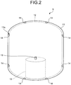
- FIG. 2 is a schematic configuration diagram schematically illustrating the inside of a fuel tank and an oxidant tank.
- a propellant tank according to the present embodiment is a tank for accumulating propellant to be used in a spacecraft.
- the propellant for example, liquid hydrogen (LH 2 ) as fuel and liquid oxygen (LO 2 ) as oxidant are applied. That is, the propellant tank is applied to a fuel tank 6 that accumulates liquid hydrogen and an oxidant tank 7 that accumulates liquid oxygen.
- the spacecraft there are a flying object such as a rocket, a space satellite, a space station, and the like.
- the spacecraft is applied to a rocket 1 and described. First, the rocket 1 provided with the fuel tank 6 and the oxidant tank 7 is described with reference to FIG. 1 .
- the rocket 1 includes a frame 5, the fuel tank 6 supported on one side of the frame 5 (an upper side in FIG. 1 ), the oxidant tank 7 supported on the other side (a lower side in FIG. 1 ) of the frame 5, a rocket engine 8 that burns fuel to generate propulsive force, and a gas reservoir 9.
- the frame 5 has a truss structure and is provided between the fuel tank 6 and the oxidant tank 7.
- the frame 5 is fixed to the fuel tank 6 on one side, and fixed to the oxidant tank 7 on the other side, thereby supporting the fuel tank 6 and the oxidant tank 7.
- the fuel tank 6 is a liquid hydrogen tank for accumulating, for example, ultracold liquid hydrogen as fuel.
- the fuel tank 6 is supplied with operating gas from the gas reservoir 9 so that the inside thereof is pressurized, thereby enabling to supply liquid hydrogen toward the rocket engine 8.
- the oxidant tank 7 is a liquid oxygen tank for accumulating, for example, ultracold liquid oxygen as oxidant.
- the oxidant tank 7 is supplied with operating gas from the gas reservoir 9 so that the inside thereof is pressurized, thereby enabling to supply liquid oxygen toward the rocket engine 8.
- the oxidant tank 7 is disposed opposite to the fuel tank 6, having the frame 5 therebetween.
- the rocket engine 8 is provided below the oxidant tank 7, that is, on the side opposite to the fuel tank 6, having the oxidant tank 7 therebetween.
- the rocket engine 8 mixes and burns the liquid hydrogen supplied from the fuel tank 6 and the liquid oxygen supplied from the oxidant tank 7, to generate propulsive force. In this manner, the rocket engine 8 generates propulsive force by using fuel and oxidant in a liquid state.
- the gas reservoir 9 is formed in a spherical shape with the inside being hollow, and accumulates operating gas for pressurizing the insides of the fuel tank 6 and the oxidant tank 7.
- the gas reservoir 9 is disposed below the oxidant tank 7 and on an outer peripheral side of the oxidant tank 7.
- the liquid hydrogen accumulated in the fuel tank 6 accumulates on a bottom side (the other side) of the fuel tank 6 due to the propulsive force (acceleration).
- the liquid oxygen accumulated in the oxidant tank 7 accumulates on a bottom side (the other side) of the oxidant tank 7 due to the propulsive force (acceleration).
- the insides of the fuel tank 6 and the oxidant tank 7 become a microgravity state or a zero-gravity state.
- the microgravity state can be generated by propulsive force applied by the thruster or the like provided in the rocket 1.
- the liquid hydrogen accumulated in the fuel tank 6 is suspended in the fuel tank 6.
- the liquid oxygen accumulated in the oxidant tank 7 is suspended in the oxidant tank 7.
- the fuel tank 6 includes a tank body 11, a holding container 12 provided inside the tank body 11, a reservoir container 13 provided inside the holding container 12, and spacers (connection members) 14 provided between the tank body 11 and the holding container 12.
- the tank body 11 is formed in a cylindrical shape.
- a plurality of ribs 11a for fixing the holding container 12 via the spacers 14 are formed on an inner wall of the tank body 11. Further, the tank body 11 is provided with a discharge port (not illustrated) for discharging liquid hydrogen, and a gas pressurization port (not illustrated) for causing operating gas supplied from the gas reservoir 9 to flow into the tank body 11.
- the holding container 12 is provided inside the tank body 11, and is disposed with a predetermined gap from the inner wall of the tank body 11. Therefore, the holding container 12 is a small bag-shaped container slightly smaller than the tank body 11. The holding container 12 is connected to the inside of the tank body 11 via the spacer 14 and fixed thereto.
- the holding container 12 is configured by using wire mesh having a mesh pattern.
- the wire mesh has resistance properties against ultracold liquid hydrogen.
- the wire mesh has a function of holding liquid hydrogen therein when the inside of the tank body 11 is in a microgravity state or a zero-gravity state, and allowing the liquid hydrogen to pass therethrough when propulsive force (gravitational force) by means of combustion of the rocket engine 8 is applied to the inside of the tank body 11.
- the wire mesh has a function of holding the liquid hydrogen therein at the time of non-pressurization by operating gas, and allowing the liquid hydrogen to pass therethrough at the time of pressurization by the operating gas.
- the mesh of the wire mesh is set to a preferable one depending on conditions of the propellant to be used, disturbance, or the microgravity state.
- a preferable example of the mesh of the wire mesh is 400 mesh or more.
- the wire mesh configured in this manner has a configuration in which the surface tension of the liquid hydrogen can act thereon. That is, when there is no pressure by the operating gas, when the pressure by the operating gas is smaller than the surface tension of the liquid hydrogen, or when the propulsive force of the rocket 1 is smaller than the surface tension, the holding container 12 can hold the liquid hydrogen therein by suppressing passage of the liquid hydrogen. On the other hand, when the pressure by the operating gas is larger than the surface tension of the liquid hydrogen, or when the propulsive force of the rocket 1 is larger than the surface tension thereof, the holding container 12 can allow the liquid hydrogen to pass therethrough and flow outside.
- the holding container 12 has a uniform number of mesh openings over the entire area.
- wire mesh having a configuration in which the surface tension of the liquid hydrogen can act thereon and the weight thereof is light is used. That is, by the holding container 12 having a uniform number of mesh openings over the entire area, wire mesh with lightweight can be used over the entire area, thereby enabling to suppress an increase in weight.
- the spacer 14 is to connect the inner wall of the tank body 11 and the holding container 12 with each other, and is provided at a plurality of positions.
- the spacer 14 is configured by using a low heat-conducting material, and as the low heat-conducting material, for example, fiber reinforced plastics (FRP) is used.
- the material of the spacer is not limited to the low heat-conducting material, and titanium alloy or the like can be used.
- the spacer 14 is connected at one end to the rib 11a formed on the inner wall of the tank body 11, and at the other end to an outer surface of the holding container 12. By providing the spacers 14, a predetermined gap is maintained between the inner wall of the tank body 11 and the holding container 12.
- the reservoir container 13 is provided inside the holding container 12 and on the discharge port side (on the lower side in FIG. 2 ) for discharging liquid hydrogen.
- the reservoir container 13 is, for example, a cylindrical bag-shaped container, and is attached in contact with an inner surface of the holding container 12.
- the reservoir container 13 is configured by using wire mesh having a mesh pattern similarly to the holding container 12. That is, the wire mesh of the reservoir container 13 has a function of holding the liquid hydrogen therein at the time of non-pressurization by the operating gas, and allowing the liquid hydrogen to pass therethrough at the time of pressurization by the operating gas.
- the wire mesh used in the reservoir container 13 can be identical to the wire mesh used in the holding container 12, or can be different from each other.
- a relief valve 15 is provided in the reservoir container 13 in a portion opposite to a portion with which the holding container 12 comes in contact.
- the relief valve 15 is a valve for discharging gas phase hydrogen generated inside the reservoir container 13. While the relief valve 15 is opened when the pressure in the reservoir container 13 becomes a predetermined pressure or higher, the relief valve 15 is closed when the pressure in the reservoir container 13 becomes lower than the predetermined pressure.
- the liquid hydrogen suspended in the holding container 12 of the fuel tank 6 passes through the holding container 12 due to the pressure of the operating gas. Therefore, the liquid hydrogen passes through the holding container 12 and flows toward the discharge port.
- the liquid hydrogen suspended in the reservoir container 13 of the fuel tank 6 passes through the reservoir container 13 due to the pressure of the operating gas and flows toward the discharge port.
- the rocket 1 when the rocket 1 travels in an outer space, when the inside of the tank body 11 is in a microgravity state or a zero-gravity state, suspended liquid phase propellant can be held in the holding container 12.
- a gap is formed between the inner wall of the tank body 11 and the holding container 12, it can be suppressed that the liquid phase propellant comes in contact with the inner wall of the tank body 11 and evaporates. Accordingly, because evaporation of the liquid phase propellant can be suppressed, a decrease of usable propellant can be suppressed and the propellant can be efficiently used.
- the propellant stored in the holding container 12 when the propellant is discharged toward the rocket engine 8, by pressurizing the inside of the tank body 11 by operating gas, the propellant stored in the holding container 12 can be caused to pass through the holding container 12 and can be discharged to outside of the tank body 11. Accordingly, the propellant stored in the holding container 12 can be favorably supplied toward the rocket engine 8 at the time of using the propellant.
- the liquid phase propellant can be held in the holding container 12 by the surface tension. Therefore, when the inside of the tank body 11 is in a microgravity state or a zero-gravity state, while the liquid phase propellant can be held in the holding container 12 at the time of non-pressurization by the operating gas, the liquid phase propellant can be discharged outside from the inside of the holding container 12 at the time of pressurization by the operating gas.
- the holding container 12 can be configured by using wire mesh having a mesh pattern, the surface tension can be easily set according to the number of mesh openings and the like of the wire mesh. Further, because the holding container 12 can be configured by using the wire mesh, even if ultracold liquid oxygen or ultracold liquid hydrogen is used as the propellant, the holding container 12 can have resistance properties against the propellant.
- the holding container 12 can be fixed to the inner wall of the tank body 11 by the spacers 14, while forming a gap between the holding container 12 and the inner wall of the tank body 11.
- the spacers 14 can be configured by using a low heat-conducting material, heat of the tank body 11 is hardly transferred to the holding container 12, thereby enabling to further suppress evaporation of the liquid phase propellant.
- the liquid phase propellant can be held in the reservoir container 13, the liquid phase propellant can be held on the discharge side of the propellant in the holding container 12. Therefore, at a stage before acceleration (propulsive force) is applied at the time of ignition of the rocket engine 8 and at an initial stage of ignition, if the inside of the tank body 11 is pressurized by operating gas, the liquid phase propellant can be supplied favorably to the rocket engine 8, while suppressing inflow of gas phase propellant into the rocket engine 8. Accordingly, the propellant can be favorably burned in the rocket engine 8.
- the gas phase propellant can be discharged from the reservoir container 13 via the relief valve 15. Therefore, it can be suppressed that the gas phase propellant is supplied to the rocket engine 8.
- the holding container 12 and the reservoir container 13 are formed by using wire mesh.
- the material thereof is not limited thereto.
- the holding container 12 and the reservoir container 13 can be formed by using a net configured by using polytetrafluoroethylene (a PTFE net) instead of the wire mesh.
- a PTFE net polytetrafluoroethylene
- the material thereof is not limited to a mesh material such as the wire mesh and the PTFE net, and any material can be used so long as the surface tension of the liquid phase propellant can act on the material, and for example, a porous sheet material can be used.
- the holding container 12 only needs to be wire mesh in which at least a part thereof has a mesh pattern, and a part of the holding container 12 can be wire mesh or the entire holding container 12 can be wire mesh. Further, the holding container 12 can have a uniform number of mesh openings or the number of mesh openings can be non-uniform.
Landscapes
- Engineering & Computer Science (AREA)
- Mechanical Engineering (AREA)
- General Engineering & Computer Science (AREA)
- Chemical & Material Sciences (AREA)
- Combustion & Propulsion (AREA)
- Remote Sensing (AREA)
- Aviation & Aerospace Engineering (AREA)
- Physics & Mathematics (AREA)
- Thermal Sciences (AREA)
- Filling Or Discharging Of Gas Storage Vessels (AREA)
Claims (7)
- Ein Treibstofftank (6;7) für ein Raumfahrzeug (1), das einen darin gespeicherten Treibstoff zu einer Antriebsmaschine (8) austragen kann, indem eine Innenseite davon durch ein Betriebsgas unter Druck gesetzt wird, wobei der Treibstofftank (6;7) aufweist:einen Tankkörper (11), der konfiguriert ist, um darin den Treibstoff in einem flüssigen Zustand zu speichern,einen Haltebehälter (12), der im Inneren des Tankkörpers (11) vorgesehen ist und der mit einem vorbestimmten Zwischenraum von einer Innenwand des Tankkörpers (11) angeordnet ist, sodass der Treibstoff in einem flüssigen Zustand darin gehalten werden kann, undeinen Reservoirbehälter (13), der in dem Haltebehälter (12) an einer Austragseite des Treibstoffs vorgesehen ist und der den Treibstoff in einem flüssigen Zustand darin halten kann,wobei der Haltebehälter (12) und der Reservoirbehälter (13) aus einem Netzmaterial mit einem Netzmuster konfiguriert sind, auf das eine Oberflächenspannung des Treibstoffs in einer flüssigen Zustandsstufe so einwirken kann, dass, wenn die Innenseite des Tankkörpers (11) in einem Mikrogravitätszustand oder einem Nullgravitätszustand ist und nicht durch das Betriebsgas unter Druck gesetzt ist, ein Durchgang von Flüssigkeit durch den Haltebehälter (12) mittels der Oberflächenspannung des Treibstoffs in dem flüssigen Zustand verhindert ist.
- Der Treibstofftank (6;7) für ein Raumfahrzeug (1) gemäß Anspruch 1, wobei der Haltebehälter (12) einen Durchgang des Treibstoffs in einem flüssigen Zustand zu einer Zeit der Druckbeaufschlagung durch das Betriebsgas erlaubt.
- Der Treibstofftank (6;7) für ein Raumfahrzeug (1) gemäß Anspruch 1 oder 2, wobei das Netzmaterial ein Drahtnetz ist.
- Der Treibstofftank (6;7) für ein Raumfahrzeug (1) gemäß Anspruch 1 oder 2, wobei das Netzmaterial ein unter Verwendung von Polytetrafluorethylen konfiguriertes Netz ist.
- Der Treibstofftank (6;7) für ein Raumfahrzeug (1) gemäß einem der Ansprüche 1 bis 4, ferner mit einem Verbindungselement, das die Innenwand des Tankkörpers (11) und den Haltebehälter (12) miteinander verbindet, wobei
das Verbindungselement aus einem Material mit geringer Wärmeleitfähigkeit konfiguriert ist. - Der Treibstofftank (6;7) für ein Raumfahrzeug (1) gemäß einem der Ansprüche 1 bis 5, wobei ein Entlastungsventil (15) in dem Reservoirbehälter (13) vorgesehen ist, um den Treibstoff, der zu einer Gasphase im Inneren des Reservoirbehälters geworden ist, auszutragen.
- Ein Raumfahrzeug (1) mit:einem Treibstofftank (6;7) gemäß einem der Ansprüche 1 bis 6, undeinem Gasreservoir (9), das angeordnet ist, um ein Betriebsgas zum Druckbeaufschlagen der Innenseite des Treibstofftanks (6;7) zum Austragen des Treibstoffs zuzuführen.
Applications Claiming Priority (2)
| Application Number | Priority Date | Filing Date | Title |
|---|---|---|---|
| JP2015074308A JP6590502B2 (ja) | 2015-03-31 | 2015-03-31 | 宇宙航行体用の推進薬タンク及び宇宙航行体 |
| PCT/JP2016/058870 WO2016158538A1 (ja) | 2015-03-31 | 2016-03-18 | 宇宙航行体用の推進薬タンク及び宇宙航行体 |
Publications (3)
| Publication Number | Publication Date |
|---|---|
| EP3260378A1 EP3260378A1 (de) | 2017-12-27 |
| EP3260378A4 EP3260378A4 (de) | 2018-03-21 |
| EP3260378B1 true EP3260378B1 (de) | 2019-07-03 |
Family
ID=57006165
Family Applications (1)
| Application Number | Title | Priority Date | Filing Date |
|---|---|---|---|
| EP16772420.2A Active EP3260378B1 (de) | 2015-03-31 | 2016-03-18 | Treibstofftank für raumfahrzeug und raumfahrzeug |
Country Status (4)
| Country | Link |
|---|---|
| US (1) | US10604279B2 (de) |
| EP (1) | EP3260378B1 (de) |
| JP (1) | JP6590502B2 (de) |
| WO (1) | WO2016158538A1 (de) |
Families Citing this family (6)
| Publication number | Priority date | Publication date | Assignee | Title |
|---|---|---|---|---|
| JP6590502B2 (ja) * | 2015-03-31 | 2019-10-16 | 三菱重工業株式会社 | 宇宙航行体用の推進薬タンク及び宇宙航行体 |
| JP2018093585A (ja) | 2016-11-30 | 2018-06-14 | ミネベアミツミ株式会社 | モータ |
| FR3068082B1 (fr) * | 2017-06-22 | 2019-08-09 | Airbus Safran Launchers Sas | Reservoir ameliore pour moteur d'engin spatial |
| CN117246529A (zh) * | 2017-07-21 | 2023-12-19 | 诺思路·格鲁曼系统公司 | 航天器服务装置及相关组件、系统和方法 |
| CN113631481A (zh) | 2019-01-15 | 2021-11-09 | 诺思路·格鲁曼系统公司 | 航天器服务装置及相关组件、系统和方法 |
| WO2023151865A1 (de) | 2022-02-14 | 2023-08-17 | Linde Gmbh | Speicherbehälter für kryogene flüssigkeit, wasserfahrzeug mit entsprechendem speicherbehälter und verfahren zum speichern einer kryogenen flüssigkeit |
Family Cites Families (66)
| Publication number | Priority date | Publication date | Assignee | Title |
|---|---|---|---|---|
| US3001376A (en) * | 1957-11-26 | 1961-09-26 | British Oxygen Co Ltd | Storage tanks for liquid oxygen and the like in rockets |
| US3176882A (en) * | 1960-06-09 | 1965-04-06 | Garrett Corp | Liquid reservoir |
| US3286463A (en) * | 1963-08-09 | 1966-11-22 | North American Aviation Inc | Expulsion device |
| US3304729A (en) * | 1965-10-22 | 1967-02-21 | William A Chandler | Cryogenic storage system |
| US3486302A (en) * | 1968-02-26 | 1969-12-30 | Martin Marietta Corp | Zero or reduced gravity storage system for two phase fluid |
| US3581464A (en) * | 1968-12-16 | 1971-06-01 | Trw Inc | Method of and apparatus for separating a liquid from liquid vapor and dissolved gases |
| US3720044A (en) * | 1971-01-04 | 1973-03-13 | Lockheed Aircraft Corp | Strength compounding capillary array |
| US3933448A (en) * | 1971-08-20 | 1976-01-20 | Peri Leonard J Di | Gas separator for liquid supply |
| US3854905A (en) * | 1972-04-24 | 1974-12-17 | Rca Corp | Storage system for two phase fluids |
| US3903924A (en) * | 1973-07-23 | 1975-09-09 | Sundstrand Corp | Compartmented fuel tank |
| US4013195A (en) * | 1975-02-18 | 1977-03-22 | Rockwell International Corporation | Expulsion bladder |
| US4272257A (en) * | 1976-12-06 | 1981-06-09 | Hughes Aircraft Company | Liquid-vapor separator |
| FR2484961A1 (fr) * | 1980-06-20 | 1981-12-24 | Europ Propulsion | Reservoir a tension superficielle |
| FR2486624A1 (fr) * | 1980-07-08 | 1982-01-15 | Europ Propulsion | Dispositif de stockage a tension superficielle avec reservoir-tampon |
| FR2500908A1 (fr) * | 1981-03-02 | 1982-09-03 | Europ Agence Spatiale | Installation cryogenique a fonctionnement en l'absence de gravite, notamment pour missions spatiales |
| US4482365A (en) * | 1982-03-01 | 1984-11-13 | Pall Corporation | Vortex air cleaner and self-cleaning barrier filter assembly for supercharged engines |
| US4595398A (en) * | 1984-05-21 | 1986-06-17 | Mcdonnell Douglas Corporation | Propellant acquisition device |
| JPS628900U (de) * | 1985-07-03 | 1987-01-20 | ||
| JPS628900A (ja) | 1985-07-06 | 1987-01-16 | Tokyo Keiki Co Ltd | 操船装置 |
| JPS6255299A (ja) * | 1985-09-04 | 1987-03-10 | 三菱電機株式会社 | 推薬タンク |
| US4664134A (en) * | 1985-09-30 | 1987-05-12 | The Boeing Company | Fuel system for flight vehicle |
| JPH01207151A (ja) * | 1988-02-16 | 1989-08-21 | Mitsubishi Heavy Ind Ltd | 遠心式気液分離器 |
| US4821907A (en) * | 1988-06-13 | 1989-04-18 | The United States Of America As Represented By The Administrator Of The National Aeronautics And Space Administration | Surface tension confined liquid cryogen cooler |
| US4846854A (en) * | 1988-09-30 | 1989-07-11 | The United States Of America As Represented By The United States National Aeronautics And Space Administration | System for venting gas from a liquid storage tank |
| FR2655956B1 (fr) * | 1989-12-19 | 1992-04-17 | Europ Propulsion | Reservoir a effet capillaire de coque. |
| JPH0448100A (ja) | 1990-06-15 | 1992-02-18 | Nkk Corp | 洗浄設備 |
| JPH0448100U (de) * | 1990-08-30 | 1992-04-23 | ||
| US5279323A (en) * | 1991-12-19 | 1994-01-18 | Lockheed Missiles & Space Company, Inc. | Liquid management apparatus for spacecraft |
| US5263329A (en) * | 1991-12-19 | 1993-11-23 | Lockheed Missiles & Space Company, Inc. | Flow management apparatus for cryogenic liquid |
| JPH0656097A (ja) * | 1992-08-11 | 1994-03-01 | Mitsubishi Heavy Ind Ltd | キャピラリースクリーン |
| US5398515A (en) * | 1993-05-19 | 1995-03-21 | Rockwell International Corporation | Fluid management system for a zero gravity cryogenic storage system |
| US5613366A (en) * | 1995-05-25 | 1997-03-25 | Aerojet General Corporation | System and method for regulating the temperature of cryogenic liquids |
| JPH1035595A (ja) * | 1996-07-23 | 1998-02-10 | Mitsubishi Heavy Ind Ltd | 人工衛星用燃料タンク |
| US5901557A (en) * | 1996-10-04 | 1999-05-11 | Mcdonnell Douglas Corporation | Passive low gravity cryogenic storage vessel |
| US6111187A (en) * | 1998-03-31 | 2000-08-29 | The United States Of America As Represented By The Secretary Of The Navy | Isolated compensated fluid delivery system |
| US6101816A (en) * | 1998-04-28 | 2000-08-15 | Advanced Technology Materials, Inc. | Fluid storage and dispensing system |
| US6343476B1 (en) * | 1998-04-28 | 2002-02-05 | Advanced Technology Materials, Inc. | Gas storage and dispensing system comprising regulator interiorly disposed in fluid containment vessel and adjustable in situ therein |
| US6334589B1 (en) * | 1998-05-11 | 2002-01-01 | Lockheed Martin Corporation | Cyanate ester composites for oxygen containment |
| US6360546B1 (en) * | 2000-08-10 | 2002-03-26 | Advanced Technology Materials, Inc. | Fluid storage and dispensing system featuring externally adjustable regulator assembly for high flow dispensing |
| JP4660966B2 (ja) | 2001-05-17 | 2011-03-30 | 株式会社Ihi | 液体用タンク |
| US6909839B2 (en) * | 2003-07-23 | 2005-06-21 | Advanced Technology Materials, Inc. | Delivery systems for efficient vaporization of precursor source material |
| ITRM20050347A1 (it) * | 2005-06-30 | 2007-01-01 | Finmeccanica Spa | Liner plastico integrato per serbatoi di propellente per piattaforme e sistemi di trasporto spaziali. |
| DE102005044534B3 (de) * | 2005-09-17 | 2007-06-06 | Astrium Gmbh | Treibstofftank für kryogene Flüssigkeiten |
| DE102005062092B3 (de) * | 2005-12-22 | 2007-03-29 | Eads Space Transportation Gmbh | Treibstofftank |
| US7568352B2 (en) * | 2006-02-22 | 2009-08-04 | The Boeing Company | Thermally coupled liquid oxygen and liquid methane storage vessel |
| US7900434B2 (en) * | 2006-12-20 | 2011-03-08 | The Boeing Company | Thermally-integrated fluid storage and pressurization system |
| DE102007005539B3 (de) * | 2007-02-03 | 2008-08-14 | Astrium Gmbh | Tank zur Lagerung kryogener Flüssigkeiten oder lagerfähiger flüssiger Treibstoffe |
| JP4939289B2 (ja) * | 2007-04-20 | 2012-05-23 | 三菱重工業株式会社 | 低温流体用貯蔵タンク |
| US8785881B2 (en) * | 2008-05-06 | 2014-07-22 | Massachusetts Institute Of Technology | Method and apparatus for a porous electrospray emitter |
| US10125052B2 (en) * | 2008-05-06 | 2018-11-13 | Massachusetts Institute Of Technology | Method of fabricating electrically conductive aerogels |
| DE102008026320B3 (de) * | 2008-06-03 | 2009-12-03 | Astrium Gmbh | Tank zur Lagerung kryogener Flüssigkeiten und lagerfähiger Treibstoffe |
| FR2933475B1 (fr) * | 2008-07-04 | 2010-08-27 | Snecma | Systeme de stockage de liquide cryogenique pour engin spatial |
| FR2941678B1 (fr) * | 2009-02-05 | 2011-02-18 | Air Liquide | Reservoir cryogenique et lanceur spatial comportant un tel reservoir. |
| DE102009019002B3 (de) * | 2009-04-16 | 2010-11-25 | Astrium Gmbh | Blasenfalle für Treibstofftanks in Raumflugkörpern |
| JP5509428B2 (ja) * | 2010-03-04 | 2014-06-04 | 独立行政法人 宇宙航空研究開発機構 | 蒸気噴射装置 |
| JP5509429B2 (ja) * | 2010-03-04 | 2014-06-04 | 独立行政法人 宇宙航空研究開発機構 | 推進薬タンク及びこの推進薬タンクを用いた蒸気噴射装置 |
| US9395048B1 (en) * | 2010-07-13 | 2016-07-19 | The Boeing Company | Thermally protected liquid acquisition device for cryogenic fluids |
| US8511504B2 (en) * | 2011-03-21 | 2013-08-20 | Hamilton Sundstrand Corporation | Demisable fuel supply system |
| US8534489B2 (en) * | 2011-03-21 | 2013-09-17 | Hamilton Sundstrand Space Systems International, Inc. | Demisable fuel supply system |
| JP5762093B2 (ja) * | 2011-03-31 | 2015-08-12 | 三菱重工業株式会社 | 航空機・宇宙機用流体冷却システム及び航空機・宇宙機用流体冷却方法 |
| US10308377B2 (en) * | 2011-05-03 | 2019-06-04 | Massachusetts Institute Of Technology | Propellant tank and loading for electrospray thruster |
| FR2977239B1 (fr) * | 2011-07-01 | 2015-10-23 | Air Liquide | Reservoir de fluide cryogenique et son utilisation |
| US9695983B2 (en) * | 2012-07-09 | 2017-07-04 | Gp Strategies Corporation | Fuel tank partition and method of use |
| JP6130643B2 (ja) * | 2012-10-15 | 2017-05-17 | 三菱重工業株式会社 | 液化燃料用貯蔵タンク |
| US9783324B2 (en) * | 2014-08-26 | 2017-10-10 | The Boeing Company | Vessel insulation assembly |
| JP6590502B2 (ja) * | 2015-03-31 | 2019-10-16 | 三菱重工業株式会社 | 宇宙航行体用の推進薬タンク及び宇宙航行体 |
-
2015
- 2015-03-31 JP JP2015074308A patent/JP6590502B2/ja active Active
-
2016
- 2016-03-18 WO PCT/JP2016/058870 patent/WO2016158538A1/ja active Application Filing
- 2016-03-18 EP EP16772420.2A patent/EP3260378B1/de active Active
- 2016-03-18 US US15/561,636 patent/US10604279B2/en active Active
Non-Patent Citations (1)
| Title |
|---|
| None * |
Also Published As
| Publication number | Publication date |
|---|---|
| JP2016193662A (ja) | 2016-11-17 |
| EP3260378A4 (de) | 2018-03-21 |
| US20180072436A1 (en) | 2018-03-15 |
| WO2016158538A1 (ja) | 2016-10-06 |
| JP6590502B2 (ja) | 2019-10-16 |
| EP3260378A1 (de) | 2017-12-27 |
| US10604279B2 (en) | 2020-03-31 |
Similar Documents
| Publication | Publication Date | Title |
|---|---|---|
| EP3260378B1 (de) | Treibstofftank für raumfahrzeug und raumfahrzeug | |
| JP5145062B2 (ja) | 極低温液体および貯蔵可能な燃料を貯蔵するためのタンク | |
| EP2366627B1 (de) | Treibstofftank und Dampfstrahlausstoßvorrichtung damit | |
| US8043396B2 (en) | Integrated plastic liner for propellant tanks for micro G conditions | |
| US8202357B2 (en) | Bubble trap for a fuel tank in a spacecraft | |
| CN101596939B (zh) | 用于储存低温液体和能储存的动力燃料的容器 | |
| US8769923B2 (en) | Liquid-fuel storage vessel and vapor jet system using the same | |
| US9108144B2 (en) | Tank for separating liquid from gas under weightless conditions | |
| Hartwig | Propellant management devices for low-gravity fluid management: past, present, and future applications | |
| JP4934672B2 (ja) | 極低温液体用の推進剤タンク | |
| US10611503B2 (en) | Center of mass control of liquid tanks for spacecraft use | |
| EP2366626B1 (de) | Flüssigtreibstofftank und Dampfstrahlausstoßvorrichtung damit | |
| JP2019513608A (ja) | 宇宙飛行体のための液体貯蔵タンクおよびシステムおよび推進システムならびに関連する方法 | |
| US9395048B1 (en) | Thermally protected liquid acquisition device for cryogenic fluids | |
| US4595398A (en) | Propellant acquisition device | |
| JP2017137997A (ja) | 極低温タンク、及び極低温液体の貯蔵方法 | |
| Wollen et al. | Cryogenic propellant management device: Conceptual design study | |
| US20200039659A1 (en) | Container for Receiving, Storing and Dispensing Liquids and/or Viscous Substances, in Particular Fuel, Propellant or Drinking Water, Method for Producing Same and Use Thereof | |
| KR102563410B1 (ko) | 액체 연료 탱크 | |
| Abdalla et al. | Liquid transfer demonstration on board Apollo 14 during transearth coast | |
| Behruzi et al. | Development of a propellant management device (PMD) for restartable future cryogenic upper stages | |
| JP2014227142A (ja) | 軌道内で液体を分離するためのタンク | |
| CN104249862A (zh) | 用于在天体轨道中分离液体的罐 |
Legal Events
| Date | Code | Title | Description |
|---|---|---|---|
| STAA | Information on the status of an ep patent application or granted ep patent |
Free format text: STATUS: THE INTERNATIONAL PUBLICATION HAS BEEN MADE |
|
| PUAI | Public reference made under article 153(3) epc to a published international application that has entered the european phase |
Free format text: ORIGINAL CODE: 0009012 |
|
| STAA | Information on the status of an ep patent application or granted ep patent |
Free format text: STATUS: REQUEST FOR EXAMINATION WAS MADE |
|
| 17P | Request for examination filed |
Effective date: 20170918 |
|
| AK | Designated contracting states |
Kind code of ref document: A1 Designated state(s): AL AT BE BG CH CY CZ DE DK EE ES FI FR GB GR HR HU IE IS IT LI LT LU LV MC MK MT NL NO PL PT RO RS SE SI SK SM TR |
|
| AX | Request for extension of the european patent |
Extension state: BA ME |
|
| A4 | Supplementary search report drawn up and despatched |
Effective date: 20180220 |
|
| RIC1 | Information provided on ipc code assigned before grant |
Ipc: B64G 1/40 20060101AFI20180214BHEP Ipc: F17C 13/08 20060101ALI20180214BHEP Ipc: F17C 3/04 20060101ALI20180214BHEP Ipc: F02K 9/60 20060101ALI20180214BHEP Ipc: F17C 13/00 20060101ALI20180214BHEP |
|
| DAV | Request for validation of the european patent (deleted) | ||
| DAX | Request for extension of the european patent (deleted) | ||
| GRAP | Despatch of communication of intention to grant a patent |
Free format text: ORIGINAL CODE: EPIDOSNIGR1 |
|
| STAA | Information on the status of an ep patent application or granted ep patent |
Free format text: STATUS: GRANT OF PATENT IS INTENDED |
|
| INTG | Intention to grant announced |
Effective date: 20190121 |
|
| GRAS | Grant fee paid |
Free format text: ORIGINAL CODE: EPIDOSNIGR3 |
|
| GRAA | (expected) grant |
Free format text: ORIGINAL CODE: 0009210 |
|
| STAA | Information on the status of an ep patent application or granted ep patent |
Free format text: STATUS: THE PATENT HAS BEEN GRANTED |
|
| AK | Designated contracting states |
Kind code of ref document: B1 Designated state(s): AL AT BE BG CH CY CZ DE DK EE ES FI FR GB GR HR HU IE IS IT LI LT LU LV MC MK MT NL NO PL PT RO RS SE SI SK SM TR |
|
| REG | Reference to a national code |
Ref country code: GB Ref legal event code: FG4D |
|
| REG | Reference to a national code |
Ref country code: CH Ref legal event code: EP Ref country code: AT Ref legal event code: REF Ref document number: 1150698 Country of ref document: AT Kind code of ref document: T Effective date: 20190715 |
|
| REG | Reference to a national code |
Ref country code: IE Ref legal event code: FG4D |
|
| REG | Reference to a national code |
Ref country code: DE Ref legal event code: R096 Ref document number: 602016016429 Country of ref document: DE |
|
| REG | Reference to a national code |
Ref country code: NL Ref legal event code: MP Effective date: 20190703 |
|
| REG | Reference to a national code |
Ref country code: LT Ref legal event code: MG4D |
|
| REG | Reference to a national code |
Ref country code: AT Ref legal event code: MK05 Ref document number: 1150698 Country of ref document: AT Kind code of ref document: T Effective date: 20190703 |
|
| PG25 | Lapsed in a contracting state [announced via postgrant information from national office to epo] |
Ref country code: HR Free format text: LAPSE BECAUSE OF FAILURE TO SUBMIT A TRANSLATION OF THE DESCRIPTION OR TO PAY THE FEE WITHIN THE PRESCRIBED TIME-LIMIT Effective date: 20190703 Ref country code: AT Free format text: LAPSE BECAUSE OF FAILURE TO SUBMIT A TRANSLATION OF THE DESCRIPTION OR TO PAY THE FEE WITHIN THE PRESCRIBED TIME-LIMIT Effective date: 20190703 Ref country code: LT Free format text: LAPSE BECAUSE OF FAILURE TO SUBMIT A TRANSLATION OF THE DESCRIPTION OR TO PAY THE FEE WITHIN THE PRESCRIBED TIME-LIMIT Effective date: 20190703 Ref country code: BG Free format text: LAPSE BECAUSE OF FAILURE TO SUBMIT A TRANSLATION OF THE DESCRIPTION OR TO PAY THE FEE WITHIN THE PRESCRIBED TIME-LIMIT Effective date: 20191003 Ref country code: PT Free format text: LAPSE BECAUSE OF FAILURE TO SUBMIT A TRANSLATION OF THE DESCRIPTION OR TO PAY THE FEE WITHIN THE PRESCRIBED TIME-LIMIT Effective date: 20191104 Ref country code: CZ Free format text: LAPSE BECAUSE OF FAILURE TO SUBMIT A TRANSLATION OF THE DESCRIPTION OR TO PAY THE FEE WITHIN THE PRESCRIBED TIME-LIMIT Effective date: 20190703 Ref country code: NL Free format text: LAPSE BECAUSE OF FAILURE TO SUBMIT A TRANSLATION OF THE DESCRIPTION OR TO PAY THE FEE WITHIN THE PRESCRIBED TIME-LIMIT Effective date: 20190703 Ref country code: NO Free format text: LAPSE BECAUSE OF FAILURE TO SUBMIT A TRANSLATION OF THE DESCRIPTION OR TO PAY THE FEE WITHIN THE PRESCRIBED TIME-LIMIT Effective date: 20191003 Ref country code: SE Free format text: LAPSE BECAUSE OF FAILURE TO SUBMIT A TRANSLATION OF THE DESCRIPTION OR TO PAY THE FEE WITHIN THE PRESCRIBED TIME-LIMIT Effective date: 20190703 Ref country code: FI Free format text: LAPSE BECAUSE OF FAILURE TO SUBMIT A TRANSLATION OF THE DESCRIPTION OR TO PAY THE FEE WITHIN THE PRESCRIBED TIME-LIMIT Effective date: 20190703 |
|
| PG25 | Lapsed in a contracting state [announced via postgrant information from national office to epo] |
Ref country code: RS Free format text: LAPSE BECAUSE OF FAILURE TO SUBMIT A TRANSLATION OF THE DESCRIPTION OR TO PAY THE FEE WITHIN THE PRESCRIBED TIME-LIMIT Effective date: 20190703 Ref country code: IS Free format text: LAPSE BECAUSE OF FAILURE TO SUBMIT A TRANSLATION OF THE DESCRIPTION OR TO PAY THE FEE WITHIN THE PRESCRIBED TIME-LIMIT Effective date: 20191103 Ref country code: AL Free format text: LAPSE BECAUSE OF FAILURE TO SUBMIT A TRANSLATION OF THE DESCRIPTION OR TO PAY THE FEE WITHIN THE PRESCRIBED TIME-LIMIT Effective date: 20190703 Ref country code: ES Free format text: LAPSE BECAUSE OF FAILURE TO SUBMIT A TRANSLATION OF THE DESCRIPTION OR TO PAY THE FEE WITHIN THE PRESCRIBED TIME-LIMIT Effective date: 20190703 Ref country code: GR Free format text: LAPSE BECAUSE OF FAILURE TO SUBMIT A TRANSLATION OF THE DESCRIPTION OR TO PAY THE FEE WITHIN THE PRESCRIBED TIME-LIMIT Effective date: 20191004 Ref country code: LV Free format text: LAPSE BECAUSE OF FAILURE TO SUBMIT A TRANSLATION OF THE DESCRIPTION OR TO PAY THE FEE WITHIN THE PRESCRIBED TIME-LIMIT Effective date: 20190703 |
|
| PG25 | Lapsed in a contracting state [announced via postgrant information from national office to epo] |
Ref country code: TR Free format text: LAPSE BECAUSE OF FAILURE TO SUBMIT A TRANSLATION OF THE DESCRIPTION OR TO PAY THE FEE WITHIN THE PRESCRIBED TIME-LIMIT Effective date: 20190703 |
|
| PG25 | Lapsed in a contracting state [announced via postgrant information from national office to epo] |
Ref country code: PL Free format text: LAPSE BECAUSE OF FAILURE TO SUBMIT A TRANSLATION OF THE DESCRIPTION OR TO PAY THE FEE WITHIN THE PRESCRIBED TIME-LIMIT Effective date: 20190703 Ref country code: EE Free format text: LAPSE BECAUSE OF FAILURE TO SUBMIT A TRANSLATION OF THE DESCRIPTION OR TO PAY THE FEE WITHIN THE PRESCRIBED TIME-LIMIT Effective date: 20190703 Ref country code: IT Free format text: LAPSE BECAUSE OF FAILURE TO SUBMIT A TRANSLATION OF THE DESCRIPTION OR TO PAY THE FEE WITHIN THE PRESCRIBED TIME-LIMIT Effective date: 20190703 Ref country code: DK Free format text: LAPSE BECAUSE OF FAILURE TO SUBMIT A TRANSLATION OF THE DESCRIPTION OR TO PAY THE FEE WITHIN THE PRESCRIBED TIME-LIMIT Effective date: 20190703 Ref country code: RO Free format text: LAPSE BECAUSE OF FAILURE TO SUBMIT A TRANSLATION OF THE DESCRIPTION OR TO PAY THE FEE WITHIN THE PRESCRIBED TIME-LIMIT Effective date: 20190703 |
|
| PG25 | Lapsed in a contracting state [announced via postgrant information from national office to epo] |
Ref country code: SM Free format text: LAPSE BECAUSE OF FAILURE TO SUBMIT A TRANSLATION OF THE DESCRIPTION OR TO PAY THE FEE WITHIN THE PRESCRIBED TIME-LIMIT Effective date: 20190703 Ref country code: SK Free format text: LAPSE BECAUSE OF FAILURE TO SUBMIT A TRANSLATION OF THE DESCRIPTION OR TO PAY THE FEE WITHIN THE PRESCRIBED TIME-LIMIT Effective date: 20190703 Ref country code: IS Free format text: LAPSE BECAUSE OF FAILURE TO SUBMIT A TRANSLATION OF THE DESCRIPTION OR TO PAY THE FEE WITHIN THE PRESCRIBED TIME-LIMIT Effective date: 20200224 |
|
| REG | Reference to a national code |
Ref country code: DE Ref legal event code: R097 Ref document number: 602016016429 Country of ref document: DE |
|
| PLBE | No opposition filed within time limit |
Free format text: ORIGINAL CODE: 0009261 |
|
| STAA | Information on the status of an ep patent application or granted ep patent |
Free format text: STATUS: NO OPPOSITION FILED WITHIN TIME LIMIT |
|
| PG2D | Information on lapse in contracting state deleted |
Ref country code: IS |
|
| 26N | No opposition filed |
Effective date: 20200603 |
|
| PG25 | Lapsed in a contracting state [announced via postgrant information from national office to epo] |
Ref country code: SI Free format text: LAPSE BECAUSE OF FAILURE TO SUBMIT A TRANSLATION OF THE DESCRIPTION OR TO PAY THE FEE WITHIN THE PRESCRIBED TIME-LIMIT Effective date: 20190703 |
|
| REG | Reference to a national code |
Ref country code: DE Ref legal event code: R119 Ref document number: 602016016429 Country of ref document: DE |
|
| PG25 | Lapsed in a contracting state [announced via postgrant information from national office to epo] |
Ref country code: MC Free format text: LAPSE BECAUSE OF FAILURE TO SUBMIT A TRANSLATION OF THE DESCRIPTION OR TO PAY THE FEE WITHIN THE PRESCRIBED TIME-LIMIT Effective date: 20190703 |
|
| REG | Reference to a national code |
Ref country code: CH Ref legal event code: PL |
|
| REG | Reference to a national code |
Ref country code: BE Ref legal event code: MM Effective date: 20200331 |
|
| PG25 | Lapsed in a contracting state [announced via postgrant information from national office to epo] |
Ref country code: LU Free format text: LAPSE BECAUSE OF NON-PAYMENT OF DUE FEES Effective date: 20200318 |
|
| PG25 | Lapsed in a contracting state [announced via postgrant information from national office to epo] |
Ref country code: LI Free format text: LAPSE BECAUSE OF NON-PAYMENT OF DUE FEES Effective date: 20200331 Ref country code: IE Free format text: LAPSE BECAUSE OF NON-PAYMENT OF DUE FEES Effective date: 20200318 Ref country code: CH Free format text: LAPSE BECAUSE OF NON-PAYMENT OF DUE FEES Effective date: 20200331 Ref country code: DE Free format text: LAPSE BECAUSE OF NON-PAYMENT OF DUE FEES Effective date: 20201001 |
|
| PG25 | Lapsed in a contracting state [announced via postgrant information from national office to epo] |
Ref country code: BE Free format text: LAPSE BECAUSE OF NON-PAYMENT OF DUE FEES Effective date: 20200331 |
|
| GBPC | Gb: european patent ceased through non-payment of renewal fee |
Effective date: 20200318 |
|
| PG25 | Lapsed in a contracting state [announced via postgrant information from national office to epo] |
Ref country code: GB Free format text: LAPSE BECAUSE OF NON-PAYMENT OF DUE FEES Effective date: 20200318 |
|
| PGFP | Annual fee paid to national office [announced via postgrant information from national office to epo] |
Ref country code: FR Payment date: 20210210 Year of fee payment: 6 |
|
| PG25 | Lapsed in a contracting state [announced via postgrant information from national office to epo] |
Ref country code: MT Free format text: LAPSE BECAUSE OF FAILURE TO SUBMIT A TRANSLATION OF THE DESCRIPTION OR TO PAY THE FEE WITHIN THE PRESCRIBED TIME-LIMIT Effective date: 20190703 Ref country code: CY Free format text: LAPSE BECAUSE OF FAILURE TO SUBMIT A TRANSLATION OF THE DESCRIPTION OR TO PAY THE FEE WITHIN THE PRESCRIBED TIME-LIMIT Effective date: 20190703 |
|
| PG25 | Lapsed in a contracting state [announced via postgrant information from national office to epo] |
Ref country code: MK Free format text: LAPSE BECAUSE OF FAILURE TO SUBMIT A TRANSLATION OF THE DESCRIPTION OR TO PAY THE FEE WITHIN THE PRESCRIBED TIME-LIMIT Effective date: 20190703 |
|
| PG25 | Lapsed in a contracting state [announced via postgrant information from national office to epo] |
Ref country code: FR Free format text: LAPSE BECAUSE OF NON-PAYMENT OF DUE FEES Effective date: 20220331 |