EP3260327A1 - Ensemble de phare avec structure de dissipateur de chaleur plat - Google Patents
Ensemble de phare avec structure de dissipateur de chaleur plat Download PDFInfo
- Publication number
- EP3260327A1 EP3260327A1 EP17181968.3A EP17181968A EP3260327A1 EP 3260327 A1 EP3260327 A1 EP 3260327A1 EP 17181968 A EP17181968 A EP 17181968A EP 3260327 A1 EP3260327 A1 EP 3260327A1
- Authority
- EP
- European Patent Office
- Prior art keywords
- heat sink
- sink structure
- light emitting
- emitting diode
- housing
- Prior art date
- Legal status (The legal status is an assumption and is not a legal conclusion. Google has not performed a legal analysis and makes no representation as to the accuracy of the status listed.)
- Withdrawn
Links
Images


Classifications
-
- F—MECHANICAL ENGINEERING; LIGHTING; HEATING; WEAPONS; BLASTING
- F21—LIGHTING
- F21S—NON-PORTABLE LIGHTING DEVICES; SYSTEMS THEREOF; VEHICLE LIGHTING DEVICES SPECIALLY ADAPTED FOR VEHICLE EXTERIORS
- F21S45/00—Arrangements within vehicle lighting devices specially adapted for vehicle exteriors, for purposes other than emission or distribution of light
- F21S45/40—Cooling of lighting devices
- F21S45/47—Passive cooling, e.g. using fins, thermal conductive elements or openings
-
- B—PERFORMING OPERATIONS; TRANSPORTING
- B60—VEHICLES IN GENERAL
- B60Q—ARRANGEMENT OF SIGNALLING OR LIGHTING DEVICES, THE MOUNTING OR SUPPORTING THEREOF OR CIRCUITS THEREFOR, FOR VEHICLES IN GENERAL
- B60Q1/00—Arrangement of optical signalling or lighting devices, the mounting or supporting thereof or circuits therefor
-
- F—MECHANICAL ENGINEERING; LIGHTING; HEATING; WEAPONS; BLASTING
- F21—LIGHTING
- F21S—NON-PORTABLE LIGHTING DEVICES; SYSTEMS THEREOF; VEHICLE LIGHTING DEVICES SPECIALLY ADAPTED FOR VEHICLE EXTERIORS
- F21S41/00—Illuminating devices specially adapted for vehicle exteriors, e.g. headlamps
- F21S41/10—Illuminating devices specially adapted for vehicle exteriors, e.g. headlamps characterised by the light source
- F21S41/14—Illuminating devices specially adapted for vehicle exteriors, e.g. headlamps characterised by the light source characterised by the type of light source
- F21S41/141—Light emitting diodes [LED]
- F21S41/147—Light emitting diodes [LED] the main emission direction of the LED being angled to the optical axis of the illuminating device
- F21S41/148—Light emitting diodes [LED] the main emission direction of the LED being angled to the optical axis of the illuminating device the main emission direction of the LED being perpendicular to the optical axis
-
- F—MECHANICAL ENGINEERING; LIGHTING; HEATING; WEAPONS; BLASTING
- F21—LIGHTING
- F21S—NON-PORTABLE LIGHTING DEVICES; SYSTEMS THEREOF; VEHICLE LIGHTING DEVICES SPECIALLY ADAPTED FOR VEHICLE EXTERIORS
- F21S41/00—Illuminating devices specially adapted for vehicle exteriors, e.g. headlamps
- F21S41/10—Illuminating devices specially adapted for vehicle exteriors, e.g. headlamps characterised by the light source
- F21S41/19—Attachment of light sources or lamp holders
- F21S41/192—Details of lamp holders, terminals or connectors
-
- F—MECHANICAL ENGINEERING; LIGHTING; HEATING; WEAPONS; BLASTING
- F21—LIGHTING
- F21S—NON-PORTABLE LIGHTING DEVICES; SYSTEMS THEREOF; VEHICLE LIGHTING DEVICES SPECIALLY ADAPTED FOR VEHICLE EXTERIORS
- F21S41/00—Illuminating devices specially adapted for vehicle exteriors, e.g. headlamps
- F21S41/30—Illuminating devices specially adapted for vehicle exteriors, e.g. headlamps characterised by reflectors
- F21S41/32—Optical layout thereof
- F21S41/33—Multi-surface reflectors, e.g. reflectors with facets or reflectors with portions of different curvature
- F21S41/334—Multi-surface reflectors, e.g. reflectors with facets or reflectors with portions of different curvature the reflector consisting of patch like sectors
- F21S41/336—Multi-surface reflectors, e.g. reflectors with facets or reflectors with portions of different curvature the reflector consisting of patch like sectors with discontinuity at the junction between adjacent areas
-
- F—MECHANICAL ENGINEERING; LIGHTING; HEATING; WEAPONS; BLASTING
- F21—LIGHTING
- F21S—NON-PORTABLE LIGHTING DEVICES; SYSTEMS THEREOF; VEHICLE LIGHTING DEVICES SPECIALLY ADAPTED FOR VEHICLE EXTERIORS
- F21S41/00—Illuminating devices specially adapted for vehicle exteriors, e.g. headlamps
- F21S41/30—Illuminating devices specially adapted for vehicle exteriors, e.g. headlamps characterised by reflectors
- F21S41/39—Attachment thereof
-
- F—MECHANICAL ENGINEERING; LIGHTING; HEATING; WEAPONS; BLASTING
- F21—LIGHTING
- F21S—NON-PORTABLE LIGHTING DEVICES; SYSTEMS THEREOF; VEHICLE LIGHTING DEVICES SPECIALLY ADAPTED FOR VEHICLE EXTERIORS
- F21S41/00—Illuminating devices specially adapted for vehicle exteriors, e.g. headlamps
- F21S41/40—Illuminating devices specially adapted for vehicle exteriors, e.g. headlamps characterised by screens, non-reflecting members, light-shielding members or fixed shades
- F21S41/43—Illuminating devices specially adapted for vehicle exteriors, e.g. headlamps characterised by screens, non-reflecting members, light-shielding members or fixed shades characterised by the shape thereof
- F21S41/435—Hoods or cap-shaped
-
- F—MECHANICAL ENGINEERING; LIGHTING; HEATING; WEAPONS; BLASTING
- F21—LIGHTING
- F21S—NON-PORTABLE LIGHTING DEVICES; SYSTEMS THEREOF; VEHICLE LIGHTING DEVICES SPECIALLY ADAPTED FOR VEHICLE EXTERIORS
- F21S45/00—Arrangements within vehicle lighting devices specially adapted for vehicle exteriors, for purposes other than emission or distribution of light
- F21S45/40—Cooling of lighting devices
- F21S45/47—Passive cooling, e.g. using fins, thermal conductive elements or openings
- F21S45/48—Passive cooling, e.g. using fins, thermal conductive elements or openings with means for conducting heat from the inside to the outside of the lighting devices, e.g. with fins on the outer surface of the lighting device
-
- F—MECHANICAL ENGINEERING; LIGHTING; HEATING; WEAPONS; BLASTING
- F21—LIGHTING
- F21S—NON-PORTABLE LIGHTING DEVICES; SYSTEMS THEREOF; VEHICLE LIGHTING DEVICES SPECIALLY ADAPTED FOR VEHICLE EXTERIORS
- F21S45/00—Arrangements within vehicle lighting devices specially adapted for vehicle exteriors, for purposes other than emission or distribution of light
- F21S45/40—Cooling of lighting devices
- F21S45/49—Attachment of the cooling means
-
- F—MECHANICAL ENGINEERING; LIGHTING; HEATING; WEAPONS; BLASTING
- F21—LIGHTING
- F21V—FUNCTIONAL FEATURES OR DETAILS OF LIGHTING DEVICES OR SYSTEMS THEREOF; STRUCTURAL COMBINATIONS OF LIGHTING DEVICES WITH OTHER ARTICLES, NOT OTHERWISE PROVIDED FOR
- F21V23/00—Arrangement of electric circuit elements in or on lighting devices
- F21V23/02—Arrangement of electric circuit elements in or on lighting devices the elements being transformers, impedances or power supply units, e.g. a transformer with a rectifier
-
- F—MECHANICAL ENGINEERING; LIGHTING; HEATING; WEAPONS; BLASTING
- F21—LIGHTING
- F21V—FUNCTIONAL FEATURES OR DETAILS OF LIGHTING DEVICES OR SYSTEMS THEREOF; STRUCTURAL COMBINATIONS OF LIGHTING DEVICES WITH OTHER ARTICLES, NOT OTHERWISE PROVIDED FOR
- F21V29/00—Protecting lighting devices from thermal damage; Cooling or heating arrangements specially adapted for lighting devices or systems
- F21V29/50—Cooling arrangements
- F21V29/70—Cooling arrangements characterised by passive heat-dissipating elements, e.g. heat-sinks
-
- F—MECHANICAL ENGINEERING; LIGHTING; HEATING; WEAPONS; BLASTING
- F21—LIGHTING
- F21S—NON-PORTABLE LIGHTING DEVICES; SYSTEMS THEREOF; VEHICLE LIGHTING DEVICES SPECIALLY ADAPTED FOR VEHICLE EXTERIORS
- F21S45/00—Arrangements within vehicle lighting devices specially adapted for vehicle exteriors, for purposes other than emission or distribution of light
- F21S45/60—Heating of lighting devices, e.g. for demisting
Definitions
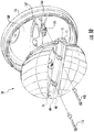
- a first embodiment of a headlamp assembly 10 for a vehicle includes a 7-in round housing 15 for coupling headlamp assembly 10 to the vehicle, first and second reflector portions 20 and 21 and a heat sink structure 25, which is a planar body that bisects housing into upper and lower areas, 27 and 28.
- Heat sink structure 25 supports light emitting diode assemblies and a circuit board, as will be discussed in detail below.
- Headlamp assembly includes a lens 30.
- Lens 30 may be formed of a hard-coated polycarbonate that is glued to housing 15 using a two component urethane.
- lens 30 includes a copper wire heating element for melting snow or ice.
- heat sink structure 25 includes a first surface 35 ( figure 2 ) and a second surface 36 ( figure 3 ).
- Heat sink structure 25 also includes a housing abutting edge 40 which is made up of first and second side edges, 42 and 43, first and second curved edges, 47 and 48, and back edge 49.
- Side edges 42 and 43 also include alignment ribs 50 for aligning heat sink structure 25 within housing 15.
- Planar heat sink 25 also includes a substantially straight edge 51, which is positioned near lens 30 in headlamp assembly 10.
- first surface 35 includes a first light emitting diode receiving portion 55, which may take the form of an indented area sized to receive a light emitting diode.
- Alignment posts, 57 and 58 may be formed in first light emitting diode receiving portion 55 for aligning with datum features in a first light emitting diode assembly 65.
- first light emitting diode assembly 65 may be accurately located on heat sink structure 25.
- first light emitting diode receiving portion 55 has holes 68 and 69 formed therein for accepting fasteners, 70 and 71, used for securing first light emitting diode assembly 65 to heat sink structure 25 in the same plane as first surface 35.
- First surface 35 also includes fastener receiving channels 73 and 74 for facilitating the attachment of screws for joining heat sink structure 25 and housing 15.
- a front angled portion 75 of heat sink structure 25 is located near substantially straight edge 51.
- Heat sink structure 25 also includes apertures 79 and 80 for receiving fasteners, generally indicated at 81, for securing first and second reflector portions, 20 and 21, to heat sink structure 25.
- An additional aperture 82 is located adjacent to back edge 49 of housing abutting edge 40 of heat sink structure 25.
- Aperture 82 is adapted to receive alignment projections 83 and 84 of first and second reflector portions, 20 and 21, for facilitating the positioning of first and second reflector portions, 20 and 21, on heat sink structure 25.
- the second surface 36 of heat sink structure 25 includes a second light emitting diode receiving portion 85 and a circuit board receiving portion 87 formed therein.
- Second light emitting diode receiving portion 85 includes alignment posts, 88 and 89, formed therein for aligning with datum features in a second light emitting diode assembly 90.
- Apertures 91 and 92 are also formed therein for accepting fasteners, 93 and 94, used for securing second light emitting diode assembly 90 to heat sink structure 25 in the same plane as second surface 36.
- circuit board receiving portion 87 is positioned near substantially straight edge 51 of heat sink structure 25 and light emitting diode receiving portion 85 is positioned near the housing abutting edge 40 of the heat sink structure.
- second light emitting diode receiving portion 85 and circuit board receiving portion 87 are adapted to support second light emitting diode 95 and a circuit board 100 in a same plane as second surface 36.
- Figure 4 is an exploded view of heat sink structure 25 with first surface 35 facing up.
- First light emitting diode assembly 65 is shown above first light emitting diode receiving portion 55.
- Alignment posts 57 and 58 correspond to apertures in first light emitting diode assembly 65.
- holes 68 and 69 formed within first light emitting diode receiving portion 55 align with fastener alignment features 102 and 103 such that fasteners 70 and 71 may secure first light emitting diode assembly 65 to heat sink structure 25.
- first light emitting diode assembly 65 is a 1x2 Altilon LED Assembly manufactured by Philips Lumiled.
- a thermally conductive compound may be positioned between heat sink structure 25 and first light emitting diode assembly 65.
- the thermally conductive compound may be a material such as thermal grease, phase change material, thermal epoxy, or thermal tape.
- An elongated opening 105 is also formed within first surface 35 of heat sink structure 25. Elongated opening 105 is formed adjacent to first light emitting diode receiving portion 55 along front angled portion 75 of first surface 35 and is adapted to receive thermal stampings 108 from a combined buss bar and light blinder assembly 110.
- Combined buss bar and light blinder assembly 110 includes a buss bar portion 111 and a light blinder portion 112.
- Bus bar portion 111 includes thermal stampings 108 that contact first light emitting diode assembly 65 at a first ends 115 and extend through elongated opening 105 of heat sink structure 25 at a second ends 117. Second ends 114 contact a circuit board 125 at openings 128 in circuit board 125, thereby forming an electrical connection between first light emitting diode assembly 65 and heat sink structure 25. Second ends 114 of buss bar portion 111 may be soldered to circuit board 125 and first ends 115 of buss bar portion 111 may be soldered to first light emitting diode assembly 65.
- An overmold 127 is positioned over thermal stampings 108 to insulate thermal stampings from heat sink structure 25, which is formed of a conductive material.
- Overmold 127 may be formed of a material suitable for high temperature applications, such as a glass filled nylon material.
- first ends 115 and second ends 117 are left uncovered to provide the necessary electrical contacts.
- thermal stampings 108 are made of tin plated brass.
- Light blinder portion 112 of heat sink structure 25 may be connected to overmold 127 with an integral extension 130. In one embodiment, light blinder portion 112 blocks light from approximately (i.e. glare zone) in a photometric pattern. Light blinder portion 112 may include bottom projections 133 for contacting first light emitting diode assembly 65. Therefore, light blinder portion 112 is positioned perpendicular to first light emitting diode assembly 65 as shown in figure 6 .
- Figure 5 is an exploded view of second surface 36 of heat sink structure 25 with second light emitting diode 95 and a circuit board 125 positioned above second light emitting diode receiving portion 85 and circuit board receiving portion 87, respectively.
- jumper wires 140 used to make an electrical connection between second light emitting diode 95 and a circuit board 125.
- a ribbon cable, buss bar, or other suitable device may be used to make an electrical connection.
- circuit board receiving portion 87 includes elongated opening 105, which extends through heat sink structure 25 from fist surface 35. Second ends 117 of thermal stampings 108 extend through elongated opening 105 such that second ends 117 contact circuit board 100 at that contact first light emitting diode assembly 65 at a first ends 115 and extend through elongated opening 105 of heat sink structure 25 at a second ends 117.
- second light emitting diode assembly 95 is a 1 x4 Altilon LED Assembly manufactured by Philips Lumiled.
- Figures 6 and 7 illustrate first and second surfaces, 35 and 36, of heat sink structure 25 in an assembled configuration.
- first surface 35 is shown with first light emitting diode assembly 65 positioned within the first light emitting diode receiving portion 55.
- combined buss bar and light blinder assembly 110 is shown with buss bar portion 111 extending into and through elongated opening 105 formed in first surface 35 and light blinder portion 112 is perpendicular to first light emitting diode assembly 65 such that light emitted in the 10U to 90U range is shielded.
- Figure 7 illustrates second surface 36 having circuit board 100 positioned within circuit board receiving portion 87.
- circuit board 100 includes electrical components on each side thereof.
- a thermal material such as a GAP pad, is used on a bottom side of circuit board 100 in order to improve thermal contact between the electrical components and heat sink structure 25.
- jumper wires 140 are shown to provide an electrical connection between second light emitting diode assembly 90 and circuit board 100.
- headlamp assembly 10 includes first and second reflector portions, 20 and 21.
- First reflector portion 20 is a low beam reflector and second reflector portion 21 is a high beam reflector. Both first and second reflector portions, 20 and 21, are molded and metalized.
- each of first and second reflector portions, 20 and 21, have a complex reflector optic design.
- the complex reflector optical design includes multiple intersecting segments. The segments intersect at points that may be profound and visible or blended to form a uniform single surface.
- First reflector portion 20 includes a heat sink abutting edge 142 having an alignment projections 83 for fitting within aperture 82 formed in first surface 35 of heat sink structure 25.
- Apertures (not shown) formed on heat sink abutting edge 142 of first reflector portion 20 align with apertures 79 and 80 of heat sink structure 25 for receiving fasteners 81 for securing first reflector portion 20 to heat sink structure 25.
- First reflector portion 20 also includes projections, one of which is indicated at 143, formed on heat sink abutting edge 142 for contacting upstanding supports 77 and 78 formed on first surface 35 of heat sink structure 25.
- second reflector portion 21 includes a heat sink abutting edge 145 having alignment projection 84 for fitting within aperture 82 formed in second surface 36 of heat sink structure 25. Additional apertures, 148 and 149, formed within heat sink abutting edge 145 of second reflector portion 21 align with apertures 79 and 80 of heat sink structure 25 for receiving fasteners 81 for securing second reflector portion 21 to heat sink structure 25.
- heat sink structure 25 When assembled, as illustrated in Figures 9a and 9b , heat sink structure 25 is positioned between first and second reflector portions, 20 and 21, thereby creating an upper area 27 and a lower area 28. Heat sink structure prevents light from upper area 27 area from impinging on second reflector portion 21 and prevents light from lower area 28 from impinging on first reflector portion 20. Heat sink abutting edge 143 of second reflector portion 21 contacts heat sink along heat sink abutting edge 143. However, heat sink abutting edge 142 of first reflector portion 20 does not contact heat sink structure 25 at front angled portion 75 thereof.
- first reflector portion 20 contact upstanding supports 77 and 78 formed on first surface 35 of heat sink structure 25 such that a contact point is provided between front angled portion 75 of heat sink structure 25 first reflector portion 20.
- Upstanding supports 77 and 78 provide stability and prevent vibration of reflector portion 20.
- Front angled portion 75 of heat sink structure 25 serves to allow light reflected first reflector portion 20 to fill foreground photometric requirements.
- FIG 10 is an exploded view of headlamp assembly 10 for illustrating the manner in which heat sink structure 25 and first and second reflector sections, 20 and 21, are attached to housing 15.
- heat sink structure 25 includes side edges 42 and 43 having alignment ribs 50 for aligning heat sink structure 25 within housing 15.
- Housing 15 includes an alignment member, such as an alignment rib receiving channel, formed on each end thereof. Therefore, alignment ribs 50 cooperate with alignments members of housing 15 to ensure that heat sink structure 25 is in a proper position upon insertion into housing 15.
- Housing 15 includes bosses formed therein for aligning with fastener receiving channels 73 and 74 of heat sink structure 25 and for receiving fasteners, generally indicated at 155, for securing heat sink structure 25 and housing 15.
- a flat surface 157 is formed on inner surface 160 of housing for contacting back edge 49 of heat sink structure.
- a thermally conductive material such as thermal grease, phase change material, thermal epoxy, or thermal tape, may be placed between back edge 49 of heat sink structure 25 and flat surface 157 of housing 15.
- An opening 165 for a wire seal 170 is also formed within housing 15 to allow wires to exit housing 15.
- Housing 15 may be formed of die-cast aluminum that is anodized black for improved thermal emissivity. Housing 15 also functions as a heat sink for first and second light emitting diode assemblies and circuit board 100.
- housing 15 may include fins 175 for providing increased surface area and greater heat dissipation.
- Housing 15 also functions as a heat sink for first and second light emitting diode assemblies, 65 and 90, and circuit board 100. Housing also serves to provide environmental protection for first and second light emitting diode assemblies, 65 and 90, circuit board 100, and any wiring components.
- a Gore-Tex patch 173 is placed within an opening in housing 15 to prevent water from entering headlamp assembly 10 while allowing water vapor to escape. Housing 15 also provides a mounting interface for attaching headlamp assembly 10 to a vehicle. In general, headlamp assembly 10 is mounted to a vehicle through the use of bucket assemblies, as is known in the art.
- Headlamp assembly 10 is adapted to emit both high and low beams.
- a low beam pattern is emitted when first light emitting diode assembly 65 is illuminated.
- a high beam pattern is emitted from headlamp assembly when both first light emitting diode assembly 65 and second light emitting diode assembly 90 are simultaneously illuminated.
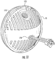
- Headlamp assembly 210 5x7 housing 215 for coupling headlamp assembly 210 to the vehicle, first and second reflector portions 220 and 221; and a planar heat sink structure 225 that bisects housing into upper and lower areas, 227 and 228. Planar heat sink structure 225 supports light emitting diode assemblies and a circuit board, as will be discussed in detail below.
- Headlamp assembly 210 includes a lens 230.
- Lens 230 may be formed of a hard-coated polycarbonate that is glued to housing 215 using a two component urethane.
- Optical elements 231 are formed in lens 230 around the perimeter of lens 230 to diffuse light in the 10U -90U glare zone.
- lens 230 includes a copper wire heating element for melting snow or ice.
- Headlamp assembly 210 is designed for mechanical aiming by the use of aiming pads (not shown) on an exterior surface of lens 230.
- a mechanical aimed lamp is generally designed to meet specific photometric requirements.
- heat sink structure 225 includes a first surface 235 ( figure 13 ) and a second surface 236 ( figure 14 ).
- Heat sink structure 225 also includes a housing abutting edge 240 which is made up of first and second side edges, 242 and 243, first and second curved edges, 247 and 248, and back edge 249.
- Side edges 242 and 243 also include alignment slots 250 for aligning heat sink structure 225 within housing 215.
- Heat sink structure 225 also includes a substantially straight edge 251, which is positioned near lens 230 in headlamp assembly 210.
- first surface 235 includes a first light emitting diode receiving portion 255, which may take the form of an indented area sized to receive a light emitting diode. Alignment posts, 257 and 258, may be formed in first light emitting diode receiving portion 255 for aligning with datum features in a first light emitting diode assembly 265. Thus, first light emitting diode assembly 265 may be accurately located on heat sink structure 225.
- first light emitting diode receiving portion 255 has holes 268 and 269 formed therein for accepting fasteners, 270 and 271, used for securing first light emitting diode assembly 265 to heat sink structure 225 in the same plane as first surface 235.
- a BUSS bar receiving portion 272 is also formed in first surface 235, as will be described in more detail below.
- First surface 235 also includes fastener receiving channels 273 and 274 for facilitating the attachment of screws for joining heat sink structure 225 and housing 215.
- Front upstanding bosses 277 and 278 are also formed adjacent to each of first and second side edges 242 and 243 for receiving fasteners for attaching first reflector portion 220 to heat sink structure 225, as will be described in detail below.
- Heat sink structure 225 also includes rear upstanding bosses 279 and 280 for receiving fasteners for securing first and second reflector portions 220 and 221 to heat sink structure 225.
- Wire channels 281 are also formed within heat sink structure for providing a passage for wires 282.
- second surface 236 of heat sink structure 225 includes a second light emitting diode receiving portion 285 and a circuit board receiving portion 287 formed therein.
- second light emitting diode receiving portion 285 is composed of upstanding walls for surrounding a second light emitting diode 290, which is positioned within circuit board receiving portion 287.
- Second light emitting diode receiving portion 285 includes alignment posts, 288 and 289, formed therein for aligning with datum features in second light emitting diode assembly 290.
- Apertures 291 and 292 are also formed therein for accepting fasteners, 293 and 294, used for securing second light emitting diode assembly 290 to heat sink structure 225 in the same plane as second surface 236.
- Second surface 236 of heat sink structure 225 also includes apertures 295-298 formed adjacent to housing abutting edge 240 for facilitating the attachment of second reflector portion 221 to heat sink structure 225.
- Figure 15 is an exploded view of heat sink structure 225 with first surface 235 facing up.
- First light emitting diode assembly 265 is shown above first light emitting diode receiving portion 255.
- Alignment posts 257 and 258 correspond to apertures in first light emitting diode assembly 265.
- holes 268 and 269 formed within first light emitting diode receiving portion 255 are adapted to receive fasteners 270 and 271 for securing first light emitting diode assembly 265 to heat sink structure 225.
- first light emitting diode assembly 265 is a 1 x4 Altilon LED Assembly manufactured by Philips Lumiled.
- a thermally conductive compound may be positioned between heat sink structure 225 and first light emitting diode assembly 265.
- the thermally conductive compound may be a material such as thermal grease, phase change material, thermal epoxy, or thermal tape.
- An elongated opening 305 is also formed through heat sink structure 225, as shown in Figure 14 .
- Elongated opening 305 is formed adjacent to BUSS bar receiving portion 272 and is adapted to receive thermal stampings 308 from BUSS bar 310.
- BUSS bar 310 includes thermal stampings 308 that contact first light emitting diode assembly 265 at a first ends 315 and extend through elongated opening 305 of heat sink structure 225 at a second ends 317. Second ends 317 contact a circuit board 325 through elongated opening 305, thereby forming an electrical connection between first light emitting diode assembly 265 and heat sink structure 225. First ends 315 of buss bar 310 may be soldered to first light emitting diode assembly 265. An overmold 327 is positioned over thermal stampings 308 to insulate thermal stampings from heat sink structure 225, which is formed of a conductive material. As noted above, first ends 315 and second ends 317 are left uncovered to provide the necessary electrical contacts. In one embodiment, thermal stampings 308 are made of tin plated brass.
- Figure 16 is an exploded view of second surface 236 of heat sink structure 225 with second light emitting diode 290 and a circuit board 325 positioned above second light emitting diode receiving portion 285 and circuit board receiving portion 287, respectively.
- a flat ribbon cable 340 is used to make an electrical connection between second light emitting diode 290 and circuit board 325.
- jumper wires, a buss bar, or other suitable device may be used to make an electrical connection.
- second light emitting diode assembly 290 is a 1x4 Altilon LED Assembly manufactured by Philips Lumiled.
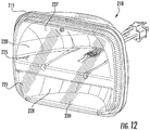
- Figures 17 and 18 illustrate first and second surfaces, 235 and 236, of heat sink structure 225 in an assembled configuration.
- first surface 235 is shown with first light emitting diode assembly 265 positioned within the first light emitting diode receiving portion 255.
- buss bar 310 is shown with overmold 327 fitted within BUSS bar receiving portion 272.
- Wires 282 extend from first light emitting diode assembly 265 through wire channels 281 formed in first surface 235 of heat sink structure 225.
- Figure 18 illustrates second surface 236 having circuit board 325 positioned within circuit board receiving portion 287.
- circuit board 325 includes electrical components on each side thereof.
- a thermal material such as a GAP pad, is used on a bottom side of circuit board 325 in order to improve thermal contact between the electrical components and heat sink structure 225.
- a flat ribbon cable 340 is used to provide an electrical connection between second light emitting diode assembly 290 and circuit board 325.
- headlamp assembly 210 includes first and second reflector portions 220 and 221.
- First reflector portion 220 is a low beam reflector and second reflector portion 221 is a high beam reflector. Both first and second reflector portions 220 and 221 are molded and metalized. In addition, each of first and second reflector portions 220 and 221 have a complex reflector optic design.
- First reflector portion 220 includes a heat sink abutting edge 342 having apertures (not shown) formed therein for aligning with upstanding bosses 277-280 of first surface 235 of heat sink structure 225.
- Fasteners 281 are used to secure first reflector portion 220 to heat sink structure 225.
- second reflector portion 221 includes a heat sink abutting edge 345 having apertures 347-350 formed therein for aligning with apertures 295-298 formed in second surface 236 of heat sink structure 225.
- Fasteners 281 extend through the apertures to secure second reflector portion 221 to heat sink structure 225.
- heat sink structure 225 When assembled, as illustrated in Figures 20a and 20b , heat sink structure 225 is positioned between first and second reflector portions 220 and 221, thereby creating an upper area 227 and a lower area 228 in headlamp assembly 210. Heat sink structure 225 prevents light from upper area 227 from impinging on second reflector portion 221 and prevents light from lower area 228 from impinging on first reflector portion 220.
- Heat sink abutting edge 345 of second reflector portion 221 contacts heat sink structure 225 to facilitate fastening of second reflector portion 221 to first surface 235 of heat sink structure 225.
- heat sink abutting edge 342 of first reflector portion 220 does not contact heat sink due to upstanding bosses 277-280, which are formed on first surface 235 of heat sink structure 225.
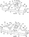
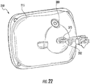
- FIG 21 is an exploded view of headlamp assembly 210 for illustrating the manner in which heat sink structure 225 and first and second reflector section 220 and 221 are attached to housing 215.
- heat sink structure 225 includes side edges 242 and 243 having alignment slots 250 for aligning heat sink structure 225 within housing 215.
- Housing 15 includes an alignment member, such as an alignment projection 355, formed on each end thereof. Therefore, alignment slots 250 cooperate with alignments members 335 of housing 215 to ensure that heat sink structure 225 is in a proper position upon insertion into housing 215.
- Housing 215 includes bosses formed therein, one of which is indicated at 360, for aligning with fastener receiving channels 273 and 274 of heat sink structure 225 and for receiving fasteners, generally indicated at 365, for securing heat sink structure 225 to housing 215.
- a thermally conductive material such as thermal grease, phase change material, thermal epoxy, or thermal tape, may be placed heat sink structure 225 and an inner surface 368 of housing 15.
- An opening 375 for a wire seal is also formed within housing 215 to allow wires 282 to exit housing 215.
- Housing 215 may be formed of die-cast aluminum that is anodized black for improved thermal emissivity. Housing 215 also functions as a heat sink for first and second light emitting diode assemblies and circuit board 325.
- housing 215 includes a Gore-Tex patch 380 is placed within an opening in housing 215 to prevent water from entering headlamp assembly 210 while allowing water vapor to escape.
- Housing 215 serves to provide environmental protection for first and second light emitting diode assemblies, 265 and 290, circuit board 325, and any wiring components.
- Housing 215 also provides a mounting interface for attaching headlamp assembly 210 to a vehicle.
- headlamp 210 emits both a high beam and a low beam.
- the low beam function uses only first reflector portion and first light emitting diode assembly.
- the high beam function uses both first and second reflector portion and both first and second light emitting diode assemblies.
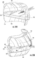
- Figures 23a and 23b illustrate additional embodiment of the heat sink structure for a 7-in round headlamp and a 5x7 in headlamp.
- Figure 23a illustrates a heat sink 400 having a second side 405.
- Light emitting diode receiving portion 407 is formed therein. The remainder of second surface is hollowed out to allow for various circuit board configurations. Once a circuit board is selected for heat sink 400, second side of heat sink is filled in to surround the circuit board.
- figure 23a illustrates a heat sink 500 for a 5x7 headlamp assembly.
- Second surface 505 is illustrated with light emitting diode receiving portion formed therein. Once a circuit board configuration is chosen, the area of second side 505 surrounding the circuit board is filled in.
- Figures 24a-24d illustrate a mounting bucket assembly 600 for headlamp assembly 10.
- Figure 24a is a front view of bucket assembly 600 having a retention spring 605, a mounting ring 608 in which lamp assembly sits, a vertical aiming screw 610 and a horizontal aiming screw 612.
- Figure 24b is a view of the bucket assembly 600 of Figure 24a .
- a bezel or retaining ring 615 is included to retain lamp assembly 10 in bucket assembly 600.
- Apertures 620 are formed in retaining ring 615 to allow access to vertical aiming screw 610 and horizontal aiming screw 612.
- Figure 24c illustrates a back view of bucket assembly 600. Threaded fasteners 625 are provided for attaching headlamp assembly 10 and bucket assembly 600 to a vehicle.
- Figure 24d is a cross-sectional view of bucket assembly 600 retaining headlamp assembly 10 therein. Although shown with respect to the 7-in round headlamp assembly, it should be understood that a corresponding bucket assembly is available for the 5x7 headlamp assembly.
- the headlamp assembly may include a housing of a 4x6 configuration. It is therefore to be understood that numerous modifications may be made to the illustrative embodiments and that other arrangements may be devised without departing from the spirit and scope of the present invention as defined by the appended claims.
Applications Claiming Priority (2)
| Application Number | Priority Date | Filing Date | Title |
|---|---|---|---|
| US13/024,320 US8845161B2 (en) | 2011-02-09 | 2011-02-09 | Headlamp assembly with heat sink structure |
| EP12774294.8A EP2673165B1 (fr) | 2011-02-09 | 2012-02-09 | Ensemble de phare à structure de dissipateur chaleur plane |
Related Parent Applications (1)
| Application Number | Title | Priority Date | Filing Date |
|---|---|---|---|
| EP12774294.8A Division EP2673165B1 (fr) | 2011-02-09 | 2012-02-09 | Ensemble de phare à structure de dissipateur chaleur plane |
Publications (1)
| Publication Number | Publication Date |
|---|---|
| EP3260327A1 true EP3260327A1 (fr) | 2017-12-27 |
Family
ID=46600534
Family Applications (2)
| Application Number | Title | Priority Date | Filing Date |
|---|---|---|---|
| EP12774294.8A Not-in-force EP2673165B1 (fr) | 2011-02-09 | 2012-02-09 | Ensemble de phare à structure de dissipateur chaleur plane |
| EP17181968.3A Withdrawn EP3260327A1 (fr) | 2011-02-09 | 2012-02-09 | Ensemble de phare avec structure de dissipateur de chaleur plat |
Family Applications Before (1)
| Application Number | Title | Priority Date | Filing Date |
|---|---|---|---|
| EP12774294.8A Not-in-force EP2673165B1 (fr) | 2011-02-09 | 2012-02-09 | Ensemble de phare à structure de dissipateur chaleur plane |
Country Status (8)
| Country | Link |
|---|---|
| US (4) | US8845161B2 (fr) |
| EP (2) | EP2673165B1 (fr) |
| AU (2) | AU2012246705B2 (fr) |
| CA (1) | CA2861948C (fr) |
| ES (1) | ES2644278T3 (fr) |
| MX (1) | MX2013009225A (fr) |
| SE (1) | SE539975C2 (fr) |
| WO (1) | WO2012145056A1 (fr) |
Cited By (1)
| Publication number | Priority date | Publication date | Assignee | Title |
|---|---|---|---|---|
| EP2535638A3 (fr) * | 2011-06-13 | 2018-07-04 | Koito Manufacturing Co., Ltd. | Phare d'automobile, mécanisme de rayonnement thermique, appareil électroluminescent et élément de fixation de source de lumière |
Families Citing this family (59)
| Publication number | Priority date | Publication date | Assignee | Title |
|---|---|---|---|---|
| US9518711B2 (en) * | 2011-09-27 | 2016-12-13 | Truck-Lite Co., Llc | Modular headlamp assembly |
| US9709238B2 (en) * | 2011-02-09 | 2017-07-18 | Truck-Lite Co., Llc | Modular headlamp assembly with a heating element for removing water based contamination |
| US8845161B2 (en) * | 2011-02-09 | 2014-09-30 | Truck-Lite Co., Llc | Headlamp assembly with heat sink structure |
| US8851723B2 (en) | 2011-05-19 | 2014-10-07 | Dialight Corporation | LED reflector optic for an automotive headlight |
| WO2012162927A1 (fr) * | 2011-06-02 | 2012-12-06 | 天津方合科技发展有限公司 | Ensemble optique à led pour phare d'automobile à faible faisceau ayant une ligne de coupure |
| US10436407B2 (en) * | 2011-09-27 | 2019-10-08 | Truck-Lite, Co., Llc | Modular headlamp assembly for producing a light distribution pattern |
| CN103133964A (zh) * | 2011-11-29 | 2013-06-05 | 株式会社小糸制作所 | 车辆用照明灯具 |
| JP5673510B2 (ja) * | 2011-11-29 | 2015-02-18 | 豊田合成株式会社 | 車両用前照灯 |
| RU2637306C2 (ru) | 2012-06-04 | 2017-12-04 | Конинклейке Филипс Н.В. | Узел светодиодной лампы, в частности для автомобильных ламп |
| FR2998944B1 (fr) * | 2012-11-30 | 2019-06-28 | Valeo Illuminacion | Dispositif d'eclairage et/ou de signalisation pour vehicule automobile |
| FR2999272A1 (fr) * | 2012-12-07 | 2014-06-13 | Valeo Illuminacion | Dispositif d'emission de lumiere pour projecteur de vehicule automobile et projecteur equipe dudit dispositif |
| FR2999275A1 (fr) * | 2012-12-07 | 2014-06-13 | Valeo Illuminacion | Dispositif d'emission de lumiere pour projecteur de vehicule automobile et projecteur equipe dudit dispositif |
| USD692168S1 (en) * | 2013-01-29 | 2013-10-22 | Myotek Pacific Corp. | LED fog lamp |
| CN104100896A (zh) * | 2013-04-07 | 2014-10-15 | 新世纪光电股份有限公司 | 车灯结构 |
| US20150070921A1 (en) * | 2013-09-10 | 2015-03-12 | Sl Corporation | Vehicle lamp |
| DE102013218356A1 (de) * | 2013-09-13 | 2015-03-19 | Automotive Lighting Reutlingen Gmbh | Lichtmodul für eine Beleuchtungseinrichtung und Beleuchtungseinrichtung mit einem solchen Lichtmodul |
| USD756001S1 (en) * | 2013-10-31 | 2016-05-10 | Bayerische Motoren Werke Aktiengesellschaft | Taillight for a vehicle |
| FR3015853B1 (fr) | 2013-12-20 | 2017-01-27 | Valeo Vision | Support de led avec connexion electrique par pontage |
| EP2915698B1 (fr) * | 2014-03-06 | 2021-05-05 | HDO -Druckguss- und Oberflächentechnik GmbH | Lampe à del |
| FR3022010B1 (fr) * | 2014-03-21 | 2019-04-05 | Valeo Iluminacion | Module lumineux d'un vehicule automobile |
| US20150282381A1 (en) * | 2014-03-27 | 2015-10-01 | Compulab Ltd. | Heat sink device |
| FR3022867B1 (fr) * | 2014-06-30 | 2016-07-15 | Valeo Vision | Dispositif lumineux pour vehicule automobile a moyens d'assemblage perfectionnes |
| WO2016049261A1 (fr) * | 2014-09-24 | 2016-03-31 | Truck-Lite Co, Llc | Phare avec sous-ensemble lentille-réflecteur |
| FR3026467B1 (fr) * | 2014-09-30 | 2019-10-04 | Valeo Vision | Module lumineux comportant au moins un composant et un connecteur disposes sur un dissipateur de chaleur, et dispositif d'eclairage pour vehicule automobile comportant un tel module |
| FR3026468B1 (fr) * | 2014-09-30 | 2019-10-04 | Valeo Vision | Dispositif a composant semi-conducteur monte sur un dissipateur de chaleur, procede de montage, et dispositif d'eclairage pour vehicule automobile comportant un tel dispositif |
| JP1534415S (fr) * | 2014-11-26 | 2015-10-05 | ||
| CN108591960A (zh) * | 2014-12-25 | 2018-09-28 | 株式会社小糸制作所 | 照明装置 |
| KR101700155B1 (ko) * | 2015-03-30 | 2017-01-26 | (주)크레스라이트 | 차량용 램프 |
| JP1542967S (fr) * | 2015-04-24 | 2016-02-01 | ||
| JP1542011S (fr) * | 2015-04-24 | 2016-01-18 | ||
| US9909752B2 (en) * | 2015-07-22 | 2018-03-06 | Putco, Inc. | LED lamp with a flexible heat sink |
| USD769481S1 (en) * | 2015-07-28 | 2016-10-18 | Ching-Tsung Lai | Automobile front light |
| USD775381S1 (en) * | 2015-07-28 | 2016-12-27 | Valeo Vision | Lighting device |
| USD788334S1 (en) * | 2015-07-30 | 2017-05-30 | Valeo Vision | Lighting device |
| JP2017069150A (ja) * | 2015-10-02 | 2017-04-06 | 株式会社小糸製作所 | 車輌用灯具 |
| USD770652S1 (en) * | 2015-10-07 | 2016-11-01 | Ching-Tsung Lai | Exterior surface configuration for a vehicle headlight |
| USD769491S1 (en) * | 2015-10-07 | 2016-10-18 | Ching-Tsung Lai | Exterior surface configuration for a vehicle headlight |
| USD788958S1 (en) * | 2016-02-15 | 2017-06-06 | In Hong Ko | Headlight for vehicles |
| USD796094S1 (en) | 2016-07-19 | 2017-08-29 | Myotek Pacific Corp. | LED fog lamp |
| USD858825S1 (en) * | 2016-12-28 | 2019-09-03 | Valeo Vision | Luminous device for a vehicle |
| FR3063048B1 (fr) * | 2017-02-20 | 2021-12-31 | Valeo Vision | Dispositif lumineux pour vehicule automobile |
| EP3375913A1 (fr) * | 2017-03-15 | 2018-09-19 | Tecomeccanica S.p.A. | Dissipateur thermique et méthode pour sa fabrication |
| US10648640B2 (en) * | 2017-03-21 | 2020-05-12 | Valeo North America, Inc. | Light emitting diode (LED) pad mount system |
| US10436403B2 (en) * | 2017-05-30 | 2019-10-08 | Valeo North America, Inc. | Dual printed circuit board |
| USD839458S1 (en) * | 2017-12-12 | 2019-01-29 | Min Hsiang Corporation | Vehicle lamp |
| USD874715S1 (en) | 2018-03-07 | 2020-02-04 | Myotek Holdings, Inc. | LED spot lamp lens |
| USD864428S1 (en) * | 2018-04-07 | 2019-10-22 | Wenpan Yang | Rectangular LED light |
| DE102018208781B4 (de) * | 2018-06-05 | 2021-06-17 | Robert Bosch Gmbh | Mobilgerät mit mindestens einer transparenten Abdeckung |
| USD937448S1 (en) * | 2018-10-24 | 2021-11-30 | Tpl Vision Uk Limited | Illumination and lighting device |
| TWD206938S (zh) | 2018-12-20 | 2020-09-01 | 法商雷諾簡化股份有限公司 | 霧燈 |
| TWD206939S (zh) | 2018-12-21 | 2020-09-01 | 法商雷諾簡化股份有限公司 | 霧燈 |
| FR3092535B1 (fr) * | 2019-02-11 | 2022-01-21 | Psa Automobiles Sa | Boîtier pour dispositif d’éclairage et de signalisation de véhicules automobiles |
| CN110440218A (zh) * | 2019-09-20 | 2019-11-12 | 嘉兴市光泰照明有限公司 | 一种led汽车车灯 |
| CN111486407A (zh) | 2019-11-30 | 2020-08-04 | 华域视觉科技(上海)有限公司 | 车灯模组、车灯及车辆 |
| US11187393B1 (en) * | 2020-12-30 | 2021-11-30 | Valeo Vision | Light system with cut-off |
| USD1010169S1 (en) * | 2021-01-18 | 2024-01-02 | Arb Corporation Limited | Driving light |
| EP4050252A1 (fr) * | 2021-02-26 | 2022-08-31 | ZKW Group GmbH | Procédé de fixation d'une vitre de fermeture pour un phare de véhicule automobile à un boitier de phare de véhicule automobile |
| US11499681B1 (en) | 2021-11-19 | 2022-11-15 | Putco, Inc. | Replacement vehicle lighting apparatus |
| CN115419859B (zh) * | 2022-08-31 | 2023-07-28 | 浙江嘉利(丽水)工业股份有限公司 | 一种反射式车灯 |
Citations (9)
| Publication number | Priority date | Publication date | Assignee | Title |
|---|---|---|---|---|
| FR2860280A1 (fr) * | 2003-09-29 | 2005-04-01 | Koito Mfg Co Ltd | Phare de vehicule a lampes a elements photoemissifs |
| EP1630474A2 (fr) * | 2004-08-24 | 2006-03-01 | Koito Manufacturing Co., Ltd | Module à émission de lumière et unité d' éclairage |
| JP2006156301A (ja) * | 2004-12-01 | 2006-06-15 | Ichikoh Ind Ltd | 車両用前照灯ユニット |
| JP2008186796A (ja) * | 2007-01-31 | 2008-08-14 | Ichikoh Ind Ltd | 発光ダイオードの固定構造 |
| DE102008011647A1 (de) * | 2007-03-14 | 2008-09-18 | Koito Manufacturing Co., Ltd. | Fahrzeugleuchte |
| US20090002997A1 (en) * | 2007-05-31 | 2009-01-01 | Koester George H | LED reflector lamp |
| WO2009037634A2 (fr) * | 2007-09-20 | 2009-03-26 | Philips Intellectual Property & Standards Gmbh | Boîtier à del et procédé de fabrication d'un boîtier à del |
| US20090154180A1 (en) * | 2007-12-18 | 2009-06-18 | Sl Seobong | Heat-dissipating apparatus |
| JP2009199779A (ja) * | 2008-02-19 | 2009-09-03 | Ichikoh Ind Ltd | 車両用灯具 |
Family Cites Families (37)
| Publication number | Priority date | Publication date | Assignee | Title |
|---|---|---|---|---|
| JP2003100114A (ja) * | 2001-09-19 | 2003-04-04 | Koito Mfg Co Ltd | 車両用灯具 |
| US6682211B2 (en) * | 2001-09-28 | 2004-01-27 | Osram Sylvania Inc. | Replaceable LED lamp capsule |
| US7048412B2 (en) * | 2002-06-10 | 2006-05-23 | Lumileds Lighting U.S., Llc | Axial LED source |
| US6945672B2 (en) | 2002-08-30 | 2005-09-20 | Gelcore Llc | LED planar light source and low-profile headlight constructed therewith |
| JP4094446B2 (ja) * | 2003-02-03 | 2008-06-04 | 株式会社小糸製作所 | 車両用前照灯及び発光モジュール |
| JP4018016B2 (ja) | 2003-03-31 | 2007-12-05 | 株式会社小糸製作所 | 車両用前照灯 |
| JP4335621B2 (ja) | 2003-04-25 | 2009-09-30 | スタンレー電気株式会社 | 車両用灯具 |
| US6976775B2 (en) * | 2003-04-25 | 2005-12-20 | Stanley Electric Co., Ltd. | Vehicle lamp |
| US7196459B2 (en) * | 2003-12-05 | 2007-03-27 | International Resistive Co. Of Texas, L.P. | Light emitting assembly with heat dissipating support |
| US7186010B2 (en) | 2004-06-16 | 2007-03-06 | Osram Sylvania Inc. | LED lamp and lamp/reflector assembly |
| WO2006033998A1 (fr) * | 2004-09-16 | 2006-03-30 | Magna International Inc. | Systeme de gestion thermique destine a des eclairages a semi-conducteurs pour automobiles |
| KR100813959B1 (ko) | 2004-10-19 | 2008-03-14 | 삼성전자주식회사 | 조명장치 |
| DE102004060890A1 (de) | 2004-12-17 | 2006-06-29 | Patent-Treuhand-Gesellschaft für elektrische Glühlampen mbH | Kfz-Scheinwerferelement |
| DE102004062990A1 (de) | 2004-12-22 | 2006-07-06 | Patent-Treuhand-Gesellschaft für elektrische Glühlampen mbH | Beleuchtungseinrichtung mit mindestens einer Leuchtdiode und Fahrzeugscheinwerfer |
| US20060187653A1 (en) * | 2005-02-10 | 2006-08-24 | Olsson Mark S | LED illumination devices |
| US7284882B2 (en) * | 2005-02-17 | 2007-10-23 | Federal-Mogul World Wide, Inc. | LED light module assembly |
| JP4697951B2 (ja) * | 2005-08-22 | 2011-06-08 | スタンレー電気株式会社 | 車両用テールランプ |
| JP4582791B2 (ja) * | 2005-08-24 | 2010-11-17 | スタンレー電気株式会社 | Led光源前照灯 |
| DE102006010977A1 (de) | 2006-02-01 | 2007-12-06 | Osram Opto Semiconductors Gmbh | Kfz-Scheinwerfer |
| US7431486B2 (en) | 2006-08-22 | 2008-10-07 | Philips Lumileds Lighting Company, Llc | LED assembly for rear lamps in an automobile |
| JP2010506410A (ja) | 2006-10-10 | 2010-02-25 | ネオバルブ テクノロジーズ,インコーポレイテッド | 熱分離を有する半導体の強力な発光モジュール |
| JP2008226707A (ja) * | 2007-03-14 | 2008-09-25 | Koito Mfg Co Ltd | 車両用灯具 |
| US20100213809A1 (en) | 2007-09-19 | 2010-08-26 | Osram Gesellschaft Mit Beschraenkter Haftung | Headlamp and its use |
| JP4992111B2 (ja) * | 2007-09-20 | 2012-08-08 | 株式会社小糸製作所 | 車両用灯具 |
| TW200916690A (en) * | 2007-10-12 | 2009-04-16 | Dosun Solar Technology Co Ltd | LED (light emitting diode) lamps |
| DE102007049310A1 (de) | 2007-10-15 | 2009-04-16 | Automotive Lighting Reutlingen Gmbh | Leuchtmodul für einen Scheinwerfer oder eine Leuchte eines Kraftfahrzeugs |
| TW200930591A (en) | 2008-01-02 | 2009-07-16 | Tyc Brother Ind Co Ltd | Projection-type head lamp capable of compensating for light of dark area |
| US7736035B2 (en) | 2008-02-13 | 2010-06-15 | Visteon Global Technologies, Inc. | Seven inch round LED headlamp |
| US20090207617A1 (en) | 2008-02-20 | 2009-08-20 | Merchant Viren B | Light emitting diode (led) connector clip |
| US7762700B2 (en) | 2008-05-28 | 2010-07-27 | Osram Sylvania Inc. | Rear-loaded light emitting diode module for automotive rear combination lamps |
| US9022612B2 (en) | 2008-08-07 | 2015-05-05 | Mag Instrument, Inc. | LED module |
| US7994725B2 (en) | 2008-11-06 | 2011-08-09 | Osram Sylvania Inc. | Floating switch controlling LED array segment |
| JP5141580B2 (ja) | 2009-01-30 | 2013-02-13 | 市光工業株式会社 | 車両用前照灯 |
| US8132947B2 (en) * | 2009-08-27 | 2012-03-13 | Jen Shieh Shih | Vehicle head light device |
| DE102009060792A1 (de) | 2009-12-22 | 2011-06-30 | Automotive Lighting Reutlingen GmbH, 72762 | Lichtmodul für eine Beleuchtungseinrichtung eines Kraftfahrzeugs mit einem solchen Lichtmodul |
| US8888318B2 (en) * | 2010-06-11 | 2014-11-18 | Intematix Corporation | LED spotlight |
| US8845161B2 (en) * | 2011-02-09 | 2014-09-30 | Truck-Lite Co., Llc | Headlamp assembly with heat sink structure |
-
2011
- 2011-02-09 US US13/024,320 patent/US8845161B2/en active Active
-
2012
- 2012-02-09 SE SE1351031A patent/SE539975C2/sv not_active IP Right Cessation
- 2012-02-09 EP EP12774294.8A patent/EP2673165B1/fr not_active Not-in-force
- 2012-02-09 WO PCT/US2012/024484 patent/WO2012145056A1/fr active Application Filing
- 2012-02-09 CA CA2861948A patent/CA2861948C/fr active Active
- 2012-02-09 ES ES12774294.8T patent/ES2644278T3/es active Active
- 2012-02-09 EP EP17181968.3A patent/EP3260327A1/fr not_active Withdrawn
- 2012-02-09 AU AU2012246705A patent/AU2012246705B2/en not_active Ceased
- 2012-02-09 MX MX2013009225A patent/MX2013009225A/es active IP Right Grant
-
2013
- 2013-11-27 US US29/473,987 patent/USD709226S1/en active Active
- 2013-11-27 US US29/473,986 patent/USD712079S1/en active Active
-
2014
- 2014-09-02 US US14/475,536 patent/US9638388B2/en active Active
-
2015
- 2015-10-09 AU AU2015238914A patent/AU2015238914B2/en not_active Ceased
Patent Citations (9)
| Publication number | Priority date | Publication date | Assignee | Title |
|---|---|---|---|---|
| FR2860280A1 (fr) * | 2003-09-29 | 2005-04-01 | Koito Mfg Co Ltd | Phare de vehicule a lampes a elements photoemissifs |
| EP1630474A2 (fr) * | 2004-08-24 | 2006-03-01 | Koito Manufacturing Co., Ltd | Module à émission de lumière et unité d' éclairage |
| JP2006156301A (ja) * | 2004-12-01 | 2006-06-15 | Ichikoh Ind Ltd | 車両用前照灯ユニット |
| JP2008186796A (ja) * | 2007-01-31 | 2008-08-14 | Ichikoh Ind Ltd | 発光ダイオードの固定構造 |
| DE102008011647A1 (de) * | 2007-03-14 | 2008-09-18 | Koito Manufacturing Co., Ltd. | Fahrzeugleuchte |
| US20090002997A1 (en) * | 2007-05-31 | 2009-01-01 | Koester George H | LED reflector lamp |
| WO2009037634A2 (fr) * | 2007-09-20 | 2009-03-26 | Philips Intellectual Property & Standards Gmbh | Boîtier à del et procédé de fabrication d'un boîtier à del |
| US20090154180A1 (en) * | 2007-12-18 | 2009-06-18 | Sl Seobong | Heat-dissipating apparatus |
| JP2009199779A (ja) * | 2008-02-19 | 2009-09-03 | Ichikoh Ind Ltd | 車両用灯具 |
Cited By (1)
| Publication number | Priority date | Publication date | Assignee | Title |
|---|---|---|---|---|
| EP2535638A3 (fr) * | 2011-06-13 | 2018-07-04 | Koito Manufacturing Co., Ltd. | Phare d'automobile, mécanisme de rayonnement thermique, appareil électroluminescent et élément de fixation de source de lumière |
Also Published As
| Publication number | Publication date |
|---|---|
| AU2012246705B2 (en) | 2015-07-09 |
| SE1351031A1 (sv) | 2013-11-08 |
| ES2644278T3 (es) | 2017-11-28 |
| AU2012246705A1 (en) | 2013-09-19 |
| AU2012246705A8 (en) | 2013-10-03 |
| USD712079S1 (en) | 2014-08-26 |
| US8845161B2 (en) | 2014-09-30 |
| AU2015238914A1 (en) | 2015-10-29 |
| EP2673165A1 (fr) | 2013-12-18 |
| MX2013009225A (es) | 2014-05-28 |
| SE539975C2 (sv) | 2018-02-13 |
| US20140369062A1 (en) | 2014-12-18 |
| CA2861948C (fr) | 2017-08-01 |
| EP2673165B1 (fr) | 2017-07-19 |
| CA2861948A1 (fr) | 2013-10-26 |
| AU2015238914B2 (en) | 2017-02-02 |
| US20120201043A1 (en) | 2012-08-09 |
| EP2673165A4 (fr) | 2014-07-30 |
| WO2012145056A1 (fr) | 2012-10-26 |
| US9638388B2 (en) | 2017-05-02 |
| USD709226S1 (en) | 2014-07-15 |
Similar Documents
| Publication | Publication Date | Title |
|---|---|---|
| AU2015238914B2 (en) | Headlamp assembly with planar heat sink structure | |
| US10415783B2 (en) | Modular headlamp assembly having a high beam module | |
| JP4500273B2 (ja) | 車両用前照灯 | |
| US8950917B2 (en) | Vehicular lamp | |
| KR101333022B1 (ko) | Led 조명 모듈 및 조명 조립품 | |
| KR101087744B1 (ko) | 차량용 램프 | |
| MX2015002314A (es) | Modulo de iluminacion para un vehiculo motorizado. | |
| EP3447364A1 (fr) | Accessoire d'alimentation et éclairage de véhicule | |
| KR100929356B1 (ko) | 엘이디기판에 반사갓이 결합되는 엘이디 가로등 | |
| US20230366521A1 (en) | Vehicle lighting unit | |
| US10670256B2 (en) | Lighting module with inclined LED mounting surface | |
| CN210291713U (zh) | 汽车灯具 | |
| JP2016046055A (ja) | 照明装置用発光ユニット及び照明装置 | |
| JP2020035698A (ja) | 車両用灯具 |
Legal Events
| Date | Code | Title | Description |
|---|---|---|---|
| PUAI | Public reference made under article 153(3) epc to a published international application that has entered the european phase |
Free format text: ORIGINAL CODE: 0009012 |
|
| STAA | Information on the status of an ep patent application or granted ep patent |
Free format text: STATUS: THE APPLICATION HAS BEEN PUBLISHED |
|
| AC | Divisional application: reference to earlier application |
Ref document number: 2673165 Country of ref document: EP Kind code of ref document: P |
|
| AK | Designated contracting states |
Kind code of ref document: A1 Designated state(s): AL AT BE BG CH CY CZ DE DK EE ES FI FR GB GR HR HU IE IS IT LI LT LU LV MC MK MT NL NO PL PT RO RS SE SI SK SM TR |
|
| STAA | Information on the status of an ep patent application or granted ep patent |
Free format text: STATUS: REQUEST FOR EXAMINATION WAS MADE |
|
| 17P | Request for examination filed |
Effective date: 20180627 |
|
| RBV | Designated contracting states (corrected) |
Designated state(s): AL AT BE BG CH CY CZ DE DK EE ES FI FR GB GR HR HU IE IS IT LI LT LU LV MC MK MT NL NO PL PT RO RS SE SI SK SM TR |
|
| GRAP | Despatch of communication of intention to grant a patent |
Free format text: ORIGINAL CODE: EPIDOSNIGR1 |
|
| STAA | Information on the status of an ep patent application or granted ep patent |
Free format text: STATUS: GRANT OF PATENT IS INTENDED |
|
| RIC1 | Information provided on ipc code assigned before grant |
Ipc: F21S 41/33 20180101ALI20200318BHEP Ipc: F21S 45/49 20180101ALI20200318BHEP Ipc: F21S 41/148 20180101AFI20200318BHEP Ipc: F21S 41/39 20180101ALI20200318BHEP Ipc: F21S 41/43 20180101ALI20200318BHEP Ipc: F21S 45/47 20180101ALI20200318BHEP Ipc: F21S 45/60 20180101ALN20200318BHEP Ipc: F21S 41/19 20180101ALI20200318BHEP Ipc: F21S 45/48 20180101ALI20200318BHEP |
|
| RIC1 | Information provided on ipc code assigned before grant |
Ipc: F21S 45/48 20180101ALI20200320BHEP Ipc: F21S 41/19 20180101ALI20200320BHEP Ipc: F21S 45/60 20180101ALN20200320BHEP Ipc: F21S 41/43 20180101ALI20200320BHEP Ipc: F21S 41/148 20180101AFI20200320BHEP Ipc: F21S 45/47 20180101ALI20200320BHEP Ipc: F21S 45/49 20180101ALI20200320BHEP Ipc: F21S 41/33 20180101ALI20200320BHEP Ipc: F21S 41/39 20180101ALI20200320BHEP |
|
| INTG | Intention to grant announced |
Effective date: 20200406 |
|
| STAA | Information on the status of an ep patent application or granted ep patent |
Free format text: STATUS: THE APPLICATION IS DEEMED TO BE WITHDRAWN |
|
| 18D | Application deemed to be withdrawn |
Effective date: 20200818 |