EP3258828B1 - Verfahren und vorrichtung zur fixationsmessung und brechungsfehlermessung mittels wellenfrontfehler - Google Patents
Verfahren und vorrichtung zur fixationsmessung und brechungsfehlermessung mittels wellenfrontfehler Download PDFInfo
- Publication number
- EP3258828B1 EP3258828B1 EP15882894.7A EP15882894A EP3258828B1 EP 3258828 B1 EP3258828 B1 EP 3258828B1 EP 15882894 A EP15882894 A EP 15882894A EP 3258828 B1 EP3258828 B1 EP 3258828B1
- Authority
- EP
- European Patent Office
- Prior art keywords
- stimulus
- eyes
- lines
- fixation
- image sensing
- Prior art date
- Legal status (The legal status is an assumption and is not a legal conclusion. Google has not performed a legal analysis and makes no representation as to the accuracy of the status listed.)
- Active
Links
- 238000000034 method Methods 0.000 title claims description 37
- 238000005259 measurement Methods 0.000 title claims description 29
- 210000001525 retina Anatomy 0.000 claims description 17
- 238000006073 displacement reaction Methods 0.000 claims description 11
- 208000014733 refractive error Diseases 0.000 claims description 10
- 241000226585 Antennaria plantaginifolia Species 0.000 claims description 4
- 230000004044 response Effects 0.000 claims description 4
- 230000007246 mechanism Effects 0.000 description 12
- 201000009310 astigmatism Diseases 0.000 description 10
- 230000003287 optical effect Effects 0.000 description 8
- 238000012545 processing Methods 0.000 description 8
- 238000004891 communication Methods 0.000 description 7
- 230000010287 polarization Effects 0.000 description 6
- 230000008901 benefit Effects 0.000 description 5
- 230000008859 change Effects 0.000 description 4
- 230000000694 effects Effects 0.000 description 4
- 238000003860 storage Methods 0.000 description 4
- 238000013461 design Methods 0.000 description 3
- 230000010354 integration Effects 0.000 description 3
- 238000004519 manufacturing process Methods 0.000 description 2
- 230000008569 process Effects 0.000 description 2
- 210000001747 pupil Anatomy 0.000 description 2
- 230000002207 retinal effect Effects 0.000 description 2
- 238000005070 sampling Methods 0.000 description 2
- 238000009987 spinning Methods 0.000 description 2
- 238000012360 testing method Methods 0.000 description 2
- 206010025421 Macule Diseases 0.000 description 1
- 238000013459 approach Methods 0.000 description 1
- 230000000295 complement effect Effects 0.000 description 1
- 210000004087 cornea Anatomy 0.000 description 1
- 230000001419 dependent effect Effects 0.000 description 1
- 230000006870 function Effects 0.000 description 1
- 201000006318 hyperopia Diseases 0.000 description 1
- 230000004305 hyperopia Effects 0.000 description 1
- 238000005286 illumination Methods 0.000 description 1
- 238000010191 image analysis Methods 0.000 description 1
- 238000003384 imaging method Methods 0.000 description 1
- 238000011835 investigation Methods 0.000 description 1
- 239000003550 marker Substances 0.000 description 1
- 239000000463 material Substances 0.000 description 1
- 208000001491 myopia Diseases 0.000 description 1
- 230000004379 myopia Effects 0.000 description 1
- 238000011160 research Methods 0.000 description 1
- 238000012552 review Methods 0.000 description 1
- 239000004065 semiconductor Substances 0.000 description 1
- 238000004088 simulation Methods 0.000 description 1
- 230000000007 visual effect Effects 0.000 description 1
Images


Classifications
-
- A—HUMAN NECESSITIES
- A61—MEDICAL OR VETERINARY SCIENCE; HYGIENE
- A61B—DIAGNOSIS; SURGERY; IDENTIFICATION
- A61B3/00—Apparatus for testing the eyes; Instruments for examining the eyes
- A61B3/10—Objective types, i.e. instruments for examining the eyes independent of the patients' perceptions or reactions
- A61B3/14—Arrangements specially adapted for eye photography
-
- A—HUMAN NECESSITIES
- A61—MEDICAL OR VETERINARY SCIENCE; HYGIENE
- A61B—DIAGNOSIS; SURGERY; IDENTIFICATION
- A61B3/00—Apparatus for testing the eyes; Instruments for examining the eyes
- A61B3/10—Objective types, i.e. instruments for examining the eyes independent of the patients' perceptions or reactions
- A61B3/103—Objective types, i.e. instruments for examining the eyes independent of the patients' perceptions or reactions for determining refraction, e.g. refractometers, skiascopes
-
- A—HUMAN NECESSITIES
- A61—MEDICAL OR VETERINARY SCIENCE; HYGIENE
- A61B—DIAGNOSIS; SURGERY; IDENTIFICATION
- A61B3/00—Apparatus for testing the eyes; Instruments for examining the eyes
- A61B3/10—Objective types, i.e. instruments for examining the eyes independent of the patients' perceptions or reactions
- A61B3/113—Objective types, i.e. instruments for examining the eyes independent of the patients' perceptions or reactions for determining or recording eye movement
-
- A—HUMAN NECESSITIES
- A61—MEDICAL OR VETERINARY SCIENCE; HYGIENE
- A61B—DIAGNOSIS; SURGERY; IDENTIFICATION
- A61B3/00—Apparatus for testing the eyes; Instruments for examining the eyes
- A61B3/10—Objective types, i.e. instruments for examining the eyes independent of the patients' perceptions or reactions
- A61B3/12—Objective types, i.e. instruments for examining the eyes independent of the patients' perceptions or reactions for looking at the eye fundus, e.g. ophthalmoscopes
-
- A—HUMAN NECESSITIES
- A61—MEDICAL OR VETERINARY SCIENCE; HYGIENE
- A61B—DIAGNOSIS; SURGERY; IDENTIFICATION
- A61B3/00—Apparatus for testing the eyes; Instruments for examining the eyes
- A61B3/0016—Operational features thereof
- A61B3/0025—Operational features thereof characterised by electronic signal processing, e.g. eye models
Definitions
- Methods of scanning a laser beam to perform measurements typically involve the mechanical movement of an optical device.
- an optical device For retinal birefringence scanning, there is a mirror that is both tilted and spinning at a high speed (e.g. 12,000 rpm).
- vibrations can present significant complexities to scanning instruments. The vibrations must be kept low enough so as not to impact the measurements intended by the instrument.
- WO2015/015454 discloses a method, including illuminating an eye with light from a light source so as to cause a first image of the light source to be formed on a retina of the eye. The method also includes capturing the light returning from the retina with a sensor so as to receive at least a portion of a second image of the first image on the sensor, and analyzing a signal from the sensor in order to determine a gaze direction of the eye.
- US5980041A discloses point of observation tracking devices for use, by way of example, in control systems, psychological research and other applications where information about the point of observation is useful.
- the inventors have identified a need for a system which measures fixation and which does not depend on polarization techniques or require any scanning mechanisms.
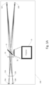
- Fig. 1A illustrates an apparatus 100 for fixation measurement according to an exemplary embodiment.
- the apparatus 100 includes a beam splitter 14, a projection system 16, a convex lens 18, focusing lenses 22A and 22B, and image sensing devices 26A and 26B.
- apparatus 100 utilizes an image-based scanning method to measure fixation.
- the above-described components of the apparatus 100 may be fixed in place - they do not need to move or rotate.
- the image-based scanning method of the present application does not rely on measurements of polarized light and therefore does not require that the surrounding environment have very low background light.
- the beam splitter 14 can be any suitable type of beam splitter.
- the projection system 16 is configured to generate a stimulus and project the generated stimulus to a projection plane 32 which is positioned below the beam splitter 14. Since this stimulus is the target fixation point for the patient who is being examined, the stimulus can also be referred to as the target.
- the target (stimulus) used in the present system is in the form of a grid of double lines.
- the projection system 16 can be any type of stimulus projection system.
- the projection system 16 can include a laser source, an axicon lens and a toroid lens which are utilized to generate and/or project the target.
- the projection system 16 can include a laser source 110, an axicon lens 112 and a toroidal lens 114.
- a round target can be generated without the need for a rotating mirror.
- the optics are rotationally symmetric.
- the projection system 16 can include a holographic device which is utilized to generate and/or project the target.
- the projection system 16 can also include diffuse media in lieu of lenses.
- the projection system 16 can include a light source (e.g., a diode laser), a first plano-convex lens, an axicon lens and a second plano-convex lens.
- the projection system 16 includes a light source 120, a first plano-convex lens 122, an axicon lens 124 and a second plano-convex lens 126.
- the light source 120 may be any suitable type of light source.
- the light source 120 can be a diode laser.
- the axicon lens 124 is positioned between the first and second plano-convex lenses 122, 126.
- the convex lens 18 may be any suitable type of convex lens and operates as a pupil reimaging lens.
- the focusing lenses 22A and 22B can be any suitable type of convex lenses, and can be selected based on the types of image analysis to be performed. Focusing lens 22A is associated with a first eye 12A of a person (such as a patient) and focusing lens 22B is associated with a second eye 12B of the person.
- the image sensing devices 26A and 26B cay be any suitable type of image sensing device.
- the image sensing devices 26A and 26B can be charge coupled device (CCD) image sensors, complementary metal-oxide-semiconductor (CMOS) image sensors, etc.
- CMOS complementary metal-oxide-semiconductor
- the image sensing devices 26A and 26B can be selected based on the desired image size and the focal length of the second and third convex lenses 22A and 22B.
- the first image sensing device 26A is associated with a first eye 12A of the person and the second image sensing device is associated with a second eye 12B of the person.
- the image sensing devices 26A and 26B can be utilized to capture, with a single image, the entire information contained from a single scan.
- the apparatus 100 can also be configured so that light reflected from both of the eyes 12A and 12B meets at a single convex lens and is imaged onto a single image sensing device.
- focusing lenses 22A and 22B can be replaced by a single convex lens and image sensing devices 26A and 26B can be replaced by a single image sensing device.
- the projection system 16 utilizes laser light to generate the target, and the projection system projects the target to the projection plane 32.
- a person hereinafter referred to as a patient
- his or her eyes 12A and 12B to look into the apparatus 100 and at the target (which appears to the patient to be in a direct line of sight)
- light representative of the target is instantaneously imaged onto the patient's eyes 12A and 12B (onto the retinas of the eyes).
- Light representative of the target enters the patient's eyes 12A and 12B and a portion of this light is reflected off the fundus of each eye.
- the reflected light passes back out the patient's eyes 12A and 12B, through the beam splitter 14, through the first convex lens 18, through the focusing lenses 22A and 22B and onto the image sensing devices 26A and 26B, which are conjugate to the patient's retinas.
- the convex lens 18 operates to converge the light onto the focusing lenses 22A and 22B.
- the specific position of the focusing lenses 22A and 22B can be determined by the requirements of the apparatus 100, such as overall size, allowable sensor locations, etc.
- the focusing lenses 22A and 22B can be considered exit pupils, and operate to focus the light onto the image sensing devices 26A and 26B, which then capture the reflected target image.
- the apparatus 100 can also be configured so that light reflected from both of the eyes 12A and 12B meets at a single convex lens and is imaged onto a single image sensing device.
- An example of this is shown in apparatus 101 of Fig. 1B , which is similar to the apparatus 100 of Fig. 1A , except that focusing lenses 22A and 22B are replaced by a single convex lens 41, image sensing devices 26A and 26B are replaced by a single image sensing device 43, and prism 39 is added to focus reflected light onto lens 41.
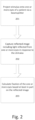
- Fig. 2 illustrates a flowchart for a method of fixation measurement according to an exemplary embodiment.
- the method, or steps in the method can be performed using an apparatus such as the one described with reference to Fig. 1A or Fig. 1B .
- a stimulus is projected onto one or more eyes of a patient via a beam splitter.
- the stimulus can be projected by an image projection system as described earlier.
- a stimulus can be generated using unpolarized laser light to create the appearance of a grid of double lines, hereinafter referred to as the target.
- the target is a double grid to provide closely spaced sets of lines.
- the proximity of the lines can be chosen such that a well-focused eye will resolve both lines, but a partial defocus (of, for example 1 ⁇ 8 diopter) will result in the lines being blurred together.
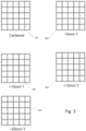
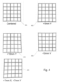
- Fig. 3 illustrates a target comprising a grid of double lines as perceived on a retina.
- the target size can vary depending on the apparatus and the patient.
- the size of the target can be 50 mm at a 300 mm range.
- image 301 When the fixation of the eyes is centered, as shown in image 301, all of the double lines in the grid are resolved and distinguishable. However, when the eyes are fixated on progressively higher points above the center point, as shown in images 302, 303, 304, and 305, part of the double lines on the opposite of the grid become blurred together, indicating a partial defocus on that region of the grid.
- a reflected image including light reflected from the one or more eyes in response to the stimulus is captured by one or more image sensing devices disposed conjugate to the one or more eyes.
- This reflected image includes information indicating the fixation of the one or more eyes.
- the nature of the optics of the eye is such that when a target is well-focused on the center of the macula, there is a distance from the center at which the target degrades from being well focused and becomes out of focus (this is a result of wavefront error). Therefore, using a double-grid set of lines, a patient looking at the target with proper focus will reveal a central region of the re-imaged target that has resolved line pairs. However, off axis, the line pairs will become smeared and rather than being resolved as two lines, they will be resolved as one line. The location of the fixation of the one or more eyes can then be determined based on how far off-center the lines are resolved.
- Fig. 4 illustrates examples of the reflected image captured by the one or more image sensing devices.
- Image 401 indicates a fixation point in the center of the grid.
- Images 402 and 403 indicate progressively higher fixation points of +5mm Y and +10mm Y. This is reflected in the blurriness of the double lines on the opposite side of the grid.
- the size of the targets in Figs. 3 and 4 are different to highlight some optical differences, especially to show that the errors generated by a single-pass through the eye ( Fig. 3 ) are smaller and less noticeable than the errors generated by a double-pass through the eye ( Fig. 4 ).
- a fixation of the one or more eyes is calculated by one or more computing devices based at least in part on the reflected image.
- the fixation of the one or more eyes can be calculated based at least in part on one or more locations of relative line-blur in the reflected image. For example, an algorithm could be used to identify all of the locations (coordinates) of line blur and then calculate a probable fixation point of the eyes based on the locations of line blur.
- the reimaged target that can be analyzed to determine fixation, and this is grid distortion. Due to the lens shapes of the various components in the eye (the anterior and posterior surfaces of the cornea, the lens), and the curvature of the retina, the reimaged target will not be imaged as a true grid of straight lines. Rather, the lines will be reimaged with slight curvature to them. Each point on the lines will be reimaged such that the further the point is from the center of the optical axis of the eye, the further the point will be dislocated off-axis when it is reimaged.
- a simple square box being viewed by a well fixated eye would have a reimaged box with sides that are pushed in toward the center (or corners that are pulled further outward from center).
- This type of optical distortion is commonly called pincushion, and can also be thought of as field-dependent magnification: the further off-axis, the greater the magnification.
- This effect can be seen in the images in Fig. 4 , which display the pincushion effect, resulting in a curvature of sides of the grid depending on the point of fixation of the one or more eyes.
- the eye does not necessarily need to be well-focused to measure fixation. If the image has a region where the lines are resolved, it helps with image processing. However even if the eyes are not focused well, there will still be a measureable change in the blur of the line pairs. Depending on which side of focus the patient may be (myopic or hyperopic), the general pattern will be that there is a roughly circular region where the focus is best. If a full circle of best focus can be measured and the center of that circle is sufficiently close to the center of the grid, then the eye has demonstrated fixation.
- the approximate magnification across the grid can be utilized, with a similar circular arrangement of values on the grid (having a center sufficiently close to the center of the grid) being an indication of fixation for the eye.
- a successful measurement - in each eye simultaneously - indicates passing the test for fixation.
- a benefit of using an image-based approach is the ability to choose the integration time for the image exposure.
- the time of the exposure ideally should be as short as possible to minimize the effects of background signals.
- the shorter the integration time the less background light that will be measured.
- the pulse can be substantially bright enough to provide significant signal during even very short integration times. This allows for a means to achieve very high signal to noise ratio, improving the image processing algorithm accuracy.
- the shorter exposure time also permits a better sampling of the retina during a scan, as it greatly reduces the amount of movement that is possible during a sampling interval.
- an image can be captured in much less than a millisecond (for example, 10us) and all the information is contained within that single image
- Images can be stored, and these are likely to offer clinical benefits as the patient ages. Any changes as a function of age would not be limited to a "pass" or "fail". An ophthalmologist would have an opportunity to review the images and determine if there is any other useful information. For example, the magnitude of the fixation error can be estimated.
- Images can be analyzed to determine the nature of the stray light, possibly allowing further investigation into methods of reducing noise.
- the imagers used to determine fixation are likely to be very useful to measure other optical characteristics of the eyes, given the appropriate design. Most notable is the desire to measure refraction error in each eye, such as astigmatism, nearsightedness, or farsightedness.
- a significant benefit to using image based measurements for fixation measurements is the ability to repurpose the image sensors to measure refraction errors.
- the methodology for measuring refraction is somewhat different than what is required for measuring fixation, the lenses and image sensors can be designed to be common to both use cases. This offers a benefit to a medical professional because it reduces the number of instruments that are needed to achieve a full examination of the patient, whether the medical professional is a pediatrician or an ophthalmologist.
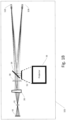
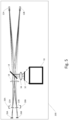
- FIG. 5 An apparatus for measurement of refractive error is shown in Fig. 5 .
- Many of the components shown in Fig. 5 are similar to those of the apparatus of Fig. 1A , including image projection system 16, beam splitter 14, convex lens 18, focusing lenses 22A and 22B, and image sensing devices 26A and 26B.
- the focusing lenses 22A and 22B and image sensing devices are also associated with one or more eyes of patient 12A and 12B.
- the nominal range for retinal birefringence scanning is 400mm, or 2.5 diopters.
- a typical patient would be accommodating to the target at this range. This would not sufficiently test a patients' ability to adjust refraction to accommodate objects at other distances. Therefore, an additional lens 34 can be added to the instrument between the viewing target and the patients' eyes 12A and 12B.
- This lens 34 can be positioned into place by the medical professional performing the refraction measurement (for example, by means of a cartridge that is pushed into place for the refraction measurement, but pulled out of place for the fixation measurement).
- the lens 34 can have a focal length and be positioned such that it is at a distance from the target to make the target appear as if it is located many meters in range (nominally less than 1/10 th diopter) and further away than it actually is.
- the image sensing devices 26A and 26B can capture images while the focusing lenses 22A and 22B that lie immediately in front of the image sensing devices 26A and 26B can be adjusted for focus.
- the focusing lenses 22A and 22B can be configured to be displaced along an axis by a focusing mechanism (not shown) to thereby alter the one or more reflected images captured by the one or more image sensing devices. For example, as shown in Fig. 5 , focusing lens 22A can be displaced along the range shown by 28A and focusing lens 22B can displaced along the range shown by 28B.
- the focus mechanism can be manufactured such that changes in the displacement of each focusing lens are well-correlated with known levels of refraction error.
- One common way to achieve this is to simply measure the position of the focus mechanism in microns. The number of microns that the focus mechanism is shifted from the nominal (no refractive error) position tells the amount of refraction error that is being measured. Therefore, based on the position of the focus mechanism that is required to achieve the best conjugate image of the retina, the patients' spherical refraction error can be measured.
- Fig. 6 illustrates a flowchart for a method of refractive error measurement according to an exemplary embodiment.
- the method, or steps in the method can be performed using an apparatus such as the one described with reference to Fig. 5 .
- a stimulus (target) is projected by an image projection system onto one or more eyes of a patient via a beam splitter.
- a lens can be disposed between the stimulus and the one or more eyes which has a focal length and position relative to the stimulus (target) such that the stimulus (target) appears to the patient to be further away than it is.
- the target being imaged would preferentially have features that would assist in the determination of this type of error.
- One example target would be comprised of a series of pairs of short lines, spaced every 3 degrees.
- An example of this type of target is similar to a watch dial, although rather than each minute marker being just one line, it would consist of a double line.
- the angular diameter of this "watch dial" target would nominally be approximately the same diameter as that used for measuring fixation error, or about 3 degrees (1.5 degrees from center to edge).
- the series of double lines in this manner would appear during an exam as being entirely in-focus at a particular focus setting for a patient with no astigmatism.
- the location of the double-lines that are in focus and out of focus will shift for a patient that has astigmatism.
- the lines that were previously well focused will then become smeared (nominally the groups of lines that are in best focus and those with the most smear will be at 90 degrees to each other). Measuring the focus shift required to achieve best focus for all of these lines will tell the magnitude of the astigmatism, whereas the midpoint between these (the position at which virtually all sets of line will be similarly smeared) will be the average refraction error.
- Another method is to simply use two concentric rings, closely spaced.
- a patient with astigmatism will exhibit images with the rings resolved in two locations, directly opposite of each other with respect to the center of the ring. The remaining sections of the ring will be smeared.
- the regions where the ring is optimally resolved will shift roughly 90 degrees.
- the astigmatism refraction error can be measured, as can the axis of the error as determined by the locations where the ring is resolved as focus is changed.
- An image target comprised of a double ring is preferable due to its ability to be used for both fixation and refraction measurements.
- one or more focusing lenses disposed between one or more image sensing devices and the one or more eyes are used to focus the light reflected from the one or more eyes onto the one or more image sensing devices.
- the one or more focusing lenses are configured to be displaced along an axis by one or more focusing mechanisms to thereby alter one or more reflected images captured by the one or more image sensing devices.
- the displacement of each of the focusing lenses can be recorded, stored, or otherwise tracked as displacement values.
- one or more image sensing devices disposed conjugate to the one or more eyes capture the one or more reflected images including light reflected from the one or more eyes in response to the stimulus (target).
- the refractive error in at least one of the one or more eyes is calculated by one or more computing devices based at least in part on the one or more reflected images and one or more displacement values of at least one of the one or more focusing lenses.
- Each of the one or more displacement values can correspond to a different reflected image in the one or more reflected images.
- the displacement amount corresponding to the reflected image which best resolves the target image can be used to determine the refractive error in an eye (such as by correlating the displacement amount with known levels of refractive error).
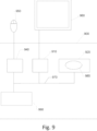
- FIG. 9 illustrates a generalized example of a computing environment 900.
- the computing environment 900 is not intended to suggest any limitation as to scope of use or functionality of a described embodiment.
- the computing environment 900 includes at least one processing unit 910 and memory 920.
- the processing unit 910 executes computer-executable instructions and may be a real or a virtual processor. In a multi-processing system, multiple processing units execute computer-executable instructions to increase processing power.
- the memory 920 may be volatile memory (e.g., registers, cache, RAM), non-volatile memory (e.g., ROM, EEPROM, flash memory, etc.), or some combination of the two.
- the memory 920 may store software instructions 980 for implementing the described techniques when executed by one or more processors.
- Memory 920 can be one memory device or multiple memory devices.
- a computing environment may have additional features.
- the computing environment 900 includes storage 940, one or more input devices 950, one or more output devices 960, and one or more communication connections 990.
- An interconnection mechanism 970 such as a bus, controller, or network interconnects the components of the computing environment 900.
- operating system software or firmware (not shown) provides an operating environment for other software executing in the computing environment 900, and coordinates activities of the components of the computing environment 900.
- the storage 940 may be removable or non-removable, and includes magnetic disks, magnetic tapes or cassettes, CD-ROMs, CD-RWs, DVDs, or any other medium which can be used to store information and which can be accessed within the computing environment 900.
- the storage 940 may store instructions for the software 980.
- the input device(s) 950 may be a touch input device such as a keyboard, mouse, pen, trackball, touch screen, or game controller, a voice input device, a scanning device, a digital camera, remote control, or another device that provides input to the computing environment 900.
- the output device(s) 960 may be a display, television, monitor, printer, speaker, or another device that provides output from the computing environment 900.
- the communication connection(s) 990 enable communication over a communication medium to another computing entity.
- the communication medium conveys information such as computer-executable instructions, audio or video information, or other data in a modulated data signal.
- a modulated data signal is a signal that has one or more of its characteristics set or changed in such a manner as to encode information in the signal.
- communication media include wired or wireless techniques implemented with an electrical, optical, RF, infrared, acoustic, or other carrier.
- Computer-readable media are any available media that can be accessed within a computing environment.
- Computer-readable media include memory 920, storage 940, communication media, and combinations of any of the above.
- FIG. 9 illustrates computing environment 900, display device 960, and input device 950 as separate devices for ease of identification only.
- Computing environment 900, display device 960, and input device 950 may be separate devices (e.g., a personal computer connected by wires to a monitor and mouse), may be integrated in a single device (e.g., a mobile device with a touch-display, such as a smartphone or a tablet), or any combination of devices (e.g., a computing device operatively coupled to a touch-screen display device, a plurality of computing devices attached to a single display device and input device, etc.).
- Computing environment 900 may be a set-top box, mobile device, personal computer, or one or more servers, for example a farm of networked servers, a clustered server environment, or a cloud network of computing devices.
Claims (9)
- Verfahren zur Fixationsmessung, wobei die Vorrichtung umfasst:einen Bildprojektor (16), welcher dazu eingerichtet ist, einen Reiz auf ein oder mehrere Augen eines Patienten mittels eines Strahlteilers (14) zu projizieren, wobei der Reiz in eine oder mehrere Netzhäute des einen oder der mehreren Augen des Patienten projiziert wird;eine oder mehrere Bild-Erfassungsvorrichtungen (26A, 26B), welche dazu eingerichtet sind, die eine oder mehreren Netzhäute zu konjugieren, wobei die eine oder mehreren Bild-Erfassungsvorrichtungen dazu eingerichtet sind, ein oder mehrere reflektierte Bilder aufzunehmen, welche Licht umfassen, welches von der einen oder den mehreren Netzhäuten in Reaktion auf den Reiz reflektiert wird, wobei das eine oder die mehreren Bilder einen wieder abgebildeten Reiz umfassen; undeine oder mehrere Computervorrichtungen, welche dazu eingerichtet sind, eine Fixation des einen oder der mehreren Augen wenigstens teilweise auf Grundlage des Reizes und des wieder abgebildeten Reizes zu berechnen,dadurch gekennzeichnet, dass der Reiz ein Netz von Doppellinien umfasst und die eine oder mehreren Computervorrichtungen dazu eingerichtet sind, die Fixation des einen oder der mehreren Augen auf Grundlage einer Kissenverzerrung in dem wieder abgebildeten Reiz relativ zu dem Reiz und/oder eines Orts einer relativen Linienverschwimmung in dem wieder abgebildeten Reiz zu berechnen.
- Vorrichtung nach Anspruch 1, wobei das Gitter von Doppellinien eng beabstandete Doppellinien umfasst und wobei eine Distanz zwischen den Doppellinien derart ist, dass ein gut fokussiertes Auge beide Linien auflösen wird, jedoch eine teilweise Defokussierung dazu führen wird, dass die Linien miteinander verschwimmen.
- Verfahren zur Fixationsmessung, wobei das Verfahren umfasst:Projizieren (201), durch einen Bildprojektor (16), eines Reizes auf ein oder mehrere Augen eines Patienten mittels eines Strahlteilers (14), wobei der Reiz auf eine oder mehrere Netzhäute des einen oder der mehreren Augen des Patienten projiziert wird;Aufnehmen (202), durch eine oder mehrere Bild-Erfassungsvorrichtungen (26A, 26B), welche konjugiert zu der einen oder den mehreren Netzhäuten angeordnet sind, von einem oder mehreren reflektierten Bildern, welche Licht umfassen, welches von der einen oder den mehreren Netzhäuten in Reaktion auf den Reiz reflektiert wird, wobei das eine oder die mehreren reflektierten Bilder einen wieder abgebildeten Reiz umfassen, undBerechnen (203), durch wenigstens eine oder mehrere Computervorrichtungen, einer Fixation des einen oder der mehreren Augen, wenigstens teilweise auf Grundlage des Reizes und des wieder abgebildeten Reizes,dadurch gekennzeichnet, dass der Reiz ein Gitter von Doppellinien umfasst und die Fixation des einen oder der mehreren Augen durch die eine oder mehreren Computervorrichtungen auf Grundlage einer Kissenverzerrung in dem wieder abgebildeten Reiz relativ zu dem Reiz und/oder eines Orts einer relativen Linienverschwimmung berechnet wird.
- Verfahren nach Anspruch 3, wobei das Gitter von Doppellinien eng beabstandete Doppellinien umfasst und wobei eine Distanz zwischen den Doppellinien derart ist, dass ein gut fokussiertes Auge beide Linien auflösen wird, jedoch eine teilweise Defokussierung dazu führen wird, dass die Linien miteinander verschwimmen.
- Vorrichtung nach einem der Ansprüche 1-2, ferner umfassend:eine Linse, welche zwischen dem Reiz und dem einen oder den mehreren Augen angeordnet ist, wobei die Linse eine Brennweise und Position relativ zu dem Reiz derart aufweist, dass der Reiz für den Patienten weiter entfernt zu sein scheint, als er es ist; undeine oder mehrere Fokussierungslinsen, welche zwischen der einen oder den mehreren Bild-Erfassungsvorrichtungen und dem einen oder den mehreren Augen angeordnet sind, wobei die eine oder die mehreren Fokussierungslinsen dazu eingerichtet sind, das von der einen oder den mehreren Netzhäuten reflektierte Licht auf die eine oder die mehreren Bild-Erfassungsvorrichtungen zu fokussieren, und wobei die eine oder mehreren Fokussierungslinsen dazu eingerichtet sind, entlang einer Achse verlagert zu werden, um dadurch das eine oder die mehreren reflektierten Bilder zu verändern, welche von der einen oder den mehreren Bild-Erfassungsvorrichtungen aufgenommen werden,wobei die eine oder mehreren Computervorrichtungen dazu eingerichtet sind, einen Brechungsfehler in wenigstes einem aus dem einen oder den mehreren Augen wenigstens teilweise auf Grundlage des einen oder der mehreren reflektierten Bilder und einem oder mehreren Verlagerungswerten von wenigstens einer aus der einen oder den mehreren Fokussierungslinsen zu berechnen, wobei jeder aus dem einen oder den mehreren Verlagerungswerten einem reflektierten Bild in dem einen oder den mehreren reflektierten Bildern entspricht.
- Vorrichtung nach einem der Ansprüche 1-2 und 5, wobei das eine oder die mehreren Augen beide Augen des Patienten umfassen.
- Vorrichtung nach Anspruch 6, wobei der Reiz zwei Ringe umfasst und wobei eine Distanz zwischen den beiden Ringen derart ist, dass ein gut fokussiertes Auge zwei Linien an dem Brennpunkt auflösen wird, jedoch eine teilweise Defokussierung dazu führen wird, dass die Linien miteinander verschwimmen.
- Verfahren nach einem der Ansprüche 3-4, ferner umfassend:Anordnen einer Linse zwischen dem Reiz und dem einen oder den mehreren Augen, welche eine Brennweite und Position relativ zu dem Reiz derart aufweist, dass der Reiz dem Patienten weiter entfernt zu sein scheint, als er es ist; undFokussieren, durch eine oder mehrere Fokussierungslinsen, welche zwischen der einen oder den mehreren Bild-Erfassungsvorrichtungen und dem einen oder den mehreren Augen angeordnet sind, von Licht, welches von der einen oder den mehreren Netzhäuten auf die eine oder die mehreren Bild-Erfassungsvorrichtungen reflektiert wird, wobei die eine oder mehreren Fokussierungslinsen dazu eingerichtet sind, entlang einer Achse verlagert zu werden, um dadurch ein oder mehrere reflektierte Bilder zu verändern, welche von der einen oder den mehreren Bild-Erfassungsvorrichtungen aufgenommen werden; undwobei das Berechnen, durch wenigstens eine oder mehrere Computervorrichtungen, ein Berechnen eines Brechungsfehlers in wenigstens einem aus dem einen oder den mehreren Augen wenigstens teilweise auf Grundlage des einen oder der mehreren reflektierten Bilder und eines oder mehrerer Verlagerungswerte von wenigstens einer aus der einen oder den mehreren Fokussierungslinsen umfasst, wobei jeder aus dem einen oder den mehreren Verlagerungswerten einem reflektierten Bild in dem einen oder den mehreren reflektierten Bildern entspricht, und wobei der Reiz zwei Ringe umfasst, und wobei eine Distanz zwischen den beiden Ringen derart ist, dass ein gut fokussiertes Auge zwei Linien an einem Brennpunkt auflösen wird, jedoch eine teilweise Defokussierung dazu führen wird, dass die Linien miteinander verschwimmen.
- Verfahren nach einem der Ansprüche 3-4 und 8, wobei das eine oder die mehreren Augen beide Augen des Patienten umfassen.
Applications Claiming Priority (2)
| Application Number | Priority Date | Filing Date | Title |
|---|---|---|---|
| US201562118894P | 2015-02-20 | 2015-02-20 | |
| PCT/US2015/067455 WO2016133588A1 (en) | 2015-02-20 | 2015-12-22 | Method and apparatus for fixation measurement and refraction error measurement using wave-front error |
Publications (3)
| Publication Number | Publication Date |
|---|---|
| EP3258828A1 EP3258828A1 (de) | 2017-12-27 |
| EP3258828A4 EP3258828A4 (de) | 2018-11-21 |
| EP3258828B1 true EP3258828B1 (de) | 2024-03-06 |
Family
ID=56689127
Family Applications (1)
| Application Number | Title | Priority Date | Filing Date |
|---|---|---|---|
| EP15882894.7A Active EP3258828B1 (de) | 2015-02-20 | 2015-12-22 | Verfahren und vorrichtung zur fixationsmessung und brechungsfehlermessung mittels wellenfrontfehler |
Country Status (6)
| Country | Link |
|---|---|
| US (2) | US9675248B2 (de) |
| EP (1) | EP3258828B1 (de) |
| JP (2) | JP6850728B2 (de) |
| AU (1) | AU2015383088B2 (de) |
| CA (1) | CA2977329C (de) |
| WO (1) | WO2016133588A1 (de) |
Families Citing this family (9)
| Publication number | Priority date | Publication date | Assignee | Title |
|---|---|---|---|---|
| ITBS20130169A1 (it) * | 2013-11-15 | 2015-05-16 | Andrea Russo | Accessorio ottico per un dispositivo mobile |
| AU2015383088B2 (en) * | 2015-02-20 | 2017-09-14 | REBIScan, Inc. | Method and apparatus for fixation measurement and refraction error measurement using wave-front error |
| US10588507B2 (en) * | 2016-10-17 | 2020-03-17 | EyeQue Inc. | Optical method to assess the refractive properties of an optical system |
| US11484195B2 (en) * | 2016-10-17 | 2022-11-01 | EyeQue Inc. | Automated personal vision tracker |
| US11484196B2 (en) * | 2016-10-17 | 2022-11-01 | EyeQue Inc. | Method and apparatus for refraction and vision measurement |
| US10474916B2 (en) | 2017-11-20 | 2019-11-12 | Ashok Krishnan | Training of vehicles to improve autonomous capabilities |
| AU2018267553B2 (en) * | 2017-11-20 | 2019-08-22 | Ashok Krishnan | Systems and methods to train vehicles |
| EP3764964A4 (de) * | 2018-03-16 | 2021-12-22 | Rebiscan, Inc. | Vorrichtung und verfahren zur ophthalmischen neuronalen abtastung |
| FI20206348A1 (en) * | 2020-12-21 | 2022-06-22 | Optomed Oyj | Optical ophthalmic device and method for focusing retinal image |
Family Cites Families (28)
| Publication number | Priority date | Publication date | Assignee | Title |
|---|---|---|---|---|
| US4145122A (en) * | 1977-05-31 | 1979-03-20 | Colorado Seminary | Method and apparatus for monitoring the position of the eye |
| US4836670A (en) * | 1987-08-19 | 1989-06-06 | Center For Innovative Technology | Eye movement detector |
| JP2648198B2 (ja) * | 1989-01-23 | 1997-08-27 | 日本電信電話株式会社 | 注視方向検出方法 |
| JPH0595903A (ja) * | 1991-10-11 | 1993-04-20 | Topcon Corp | 眼科装置 |
| JPH08104B2 (ja) * | 1992-09-17 | 1996-01-10 | 株式会社エイ・ティ・アール視聴覚機構研究所 | 奥行き視線移動検査装置 |
| US5345281A (en) * | 1992-12-17 | 1994-09-06 | John Taboada | Eye tracking system and method |
| GB9518477D0 (en) * | 1995-09-09 | 1995-11-08 | Strachan John S | Point of observation tracking system |
| US6027216A (en) * | 1997-10-21 | 2000-02-22 | The Johns University School Of Medicine | Eye fixation monitor and tracker |
| US6004313A (en) * | 1998-06-26 | 1999-12-21 | Visx, Inc. | Patient fixation system and method for laser eye surgery |
| EP1060703A3 (de) * | 1999-06-16 | 2002-06-05 | 20/10 Perfect Vision Optische Geraete GmbH | Vorrichtung und Verfahren zur Vorkompensierung von Brechungseigenschaften des menschlichen Auges mit adaptativer optischer Steuerung der Rückkopplung |
| DE19950792A1 (de) | 1999-10-21 | 2001-04-26 | Technolas Gmbh | Wellenfrontsensor mit Mehrleistungsstrahlmodi und unabhängiger Abgleichkamera |
| US6550917B1 (en) * | 2000-02-11 | 2003-04-22 | Wavefront Sciences, Inc. | Dynamic range extension techniques for a wavefront sensor including use in ophthalmic measurement |
| WO2001078585A2 (en) * | 2000-04-19 | 2001-10-25 | Alcon Universal Ltd. | Wavefront sensor for objective measurement of an optical system and associated methods |
| WO2004010860A1 (en) * | 2002-07-29 | 2004-02-05 | Daphne Instruments, Inc. | A complete autorefractor system in an ultra-compact package |
| US6736510B1 (en) * | 2003-02-04 | 2004-05-18 | Ware Tec Vision Systems, Inc. | Ophthalmic talbot-moire wavefront sensor |
| JP2004298461A (ja) * | 2003-03-31 | 2004-10-28 | Topcon Corp | 屈折測定装置 |
| US7425067B2 (en) | 2003-11-14 | 2008-09-16 | Ophthonix, Inc. | Ophthalmic diagnostic instrument |
| JP4492859B2 (ja) * | 2004-07-30 | 2010-06-30 | 株式会社ニデック | 眼屈折力測定装置 |
| US7445335B2 (en) * | 2006-01-20 | 2008-11-04 | Clarity Medical Systems, Inc. | Sequential wavefront sensor |
| US8356900B2 (en) * | 2006-01-20 | 2013-01-22 | Clarity Medical Systems, Inc. | Large diopter range real time sequential wavefront sensor |
| US8016420B2 (en) * | 2007-05-17 | 2011-09-13 | Amo Development Llc. | System and method for illumination and fixation with ophthalmic diagnostic instruments |
| WO2010054268A2 (en) * | 2008-11-06 | 2010-05-14 | Wavetec Vision Systems, Inc. | Optical angular measurement system for ophthalmic applications and method for positioning of a toric intraocular lens with increased accuracy |
| US8876290B2 (en) * | 2009-07-06 | 2014-11-04 | Wavetec Vision Systems, Inc. | Objective quality metric for ocular wavefront measurements |
| EP2453823B1 (de) * | 2009-07-14 | 2015-05-13 | WaveTec Vision Systems, Inc. | Messsystem für die augenchirurgie |
| WO2011047214A2 (en) * | 2009-10-14 | 2011-04-21 | Optimum Technologies, Inc. | Portable retinal camera and image acquisition method |
| WO2015015454A2 (en) | 2013-07-31 | 2015-02-05 | Saar Wilf | Gaze tracking system |
| ITFI20130229A1 (it) * | 2013-10-02 | 2015-04-03 | Strumenti Oftalmici C S O S R L Costruzioni | Apparato e metodo per la misura di aberrazioni del sistema ottico di un essere vivente |
| AU2015383088B2 (en) * | 2015-02-20 | 2017-09-14 | REBIScan, Inc. | Method and apparatus for fixation measurement and refraction error measurement using wave-front error |
-
2015
- 2015-12-22 AU AU2015383088A patent/AU2015383088B2/en active Active
- 2015-12-22 CA CA2977329A patent/CA2977329C/en active Active
- 2015-12-22 US US14/978,901 patent/US9675248B2/en active Active
- 2015-12-22 JP JP2017543790A patent/JP6850728B2/ja active Active
- 2015-12-22 EP EP15882894.7A patent/EP3258828B1/de active Active
- 2015-12-22 WO PCT/US2015/067455 patent/WO2016133588A1/en active Application Filing
-
2017
- 2017-05-08 US US15/588,958 patent/US10188293B2/en active Active
-
2019
- 2019-02-28 JP JP2019036610A patent/JP2019107494A/ja active Pending
Also Published As
| Publication number | Publication date |
|---|---|
| JP2018509203A (ja) | 2018-04-05 |
| AU2015383088B2 (en) | 2017-09-14 |
| AU2015383088A1 (en) | 2017-09-14 |
| CA2977329A1 (en) | 2016-08-25 |
| US9675248B2 (en) | 2017-06-13 |
| WO2016133588A1 (en) | 2016-08-25 |
| JP2019107494A (ja) | 2019-07-04 |
| EP3258828A4 (de) | 2018-11-21 |
| US20180110411A1 (en) | 2018-04-26 |
| EP3258828A1 (de) | 2017-12-27 |
| JP6850728B2 (ja) | 2021-03-31 |
| US20160242644A1 (en) | 2016-08-25 |
| CA2977329C (en) | 2018-06-19 |
| US10188293B2 (en) | 2019-01-29 |
Similar Documents
| Publication | Publication Date | Title |
|---|---|---|
| EP3258828B1 (de) | Verfahren und vorrichtung zur fixationsmessung und brechungsfehlermessung mittels wellenfrontfehler | |
| US20230255480A1 (en) | Alignment improvements for ophthalmic diagnostic systems | |
| US7891812B2 (en) | Aberrometer provided with a visual acuity testing system | |
| JP6613103B2 (ja) | 眼科装置 | |
| US20180184895A1 (en) | System and Method for Characterising Eye-Related Systems | |
| US10111584B2 (en) | Apparatus and method for fixation measurement with refraction error measurement using image sensing devices | |
| JP4252288B2 (ja) | 眼特性測定装置 | |
| JP2018143553A (ja) | 自覚式検眼装置 | |
| JP6654378B2 (ja) | 眼科装置 | |
| Neal et al. | Dynamic aberrometer/topographer designed for clinical measurement and treatment of highly aberrated eyes | |
| JP2018143554A (ja) | 自覚式検眼装置 | |
| JP2018051224A (ja) | 眼科測定装置 | |
| JP6026417B2 (ja) | 目の様々なバイオメトリックパラメータの干渉法による決定のための方法および装置 | |
| WO2015107373A1 (en) | Ophthalmic apparatus | |
| EP4326141A1 (de) | Kompaktes autozylinderkompensationsmodul für autorefraktor und autorefraktor mit autozylinderkompensationsmodul | |
| dos Santos Anjos | Development of a fundus camera for analysis of photoreceptor directionality in the healthy retina | |
| JP2016059545A (ja) | 眼屈折力測定装置 | |
| JP2017064009A (ja) | 眼科装置 |
Legal Events
| Date | Code | Title | Description |
|---|---|---|---|
| STAA | Information on the status of an ep patent application or granted ep patent |
Free format text: STATUS: THE INTERNATIONAL PUBLICATION HAS BEEN MADE |
|
| PUAI | Public reference made under article 153(3) epc to a published international application that has entered the european phase |
Free format text: ORIGINAL CODE: 0009012 |
|
| STAA | Information on the status of an ep patent application or granted ep patent |
Free format text: STATUS: REQUEST FOR EXAMINATION WAS MADE |
|
| 17P | Request for examination filed |
Effective date: 20170906 |
|
| AK | Designated contracting states |
Kind code of ref document: A1 Designated state(s): AL AT BE BG CH CY CZ DE DK EE ES FI FR GB GR HR HU IE IS IT LI LT LU LV MC MK MT NL NO PL PT RO RS SE SI SK SM TR |
|
| AX | Request for extension of the european patent |
Extension state: BA ME |
|
| DAV | Request for validation of the european patent (deleted) | ||
| DAX | Request for extension of the european patent (deleted) | ||
| A4 | Supplementary search report drawn up and despatched |
Effective date: 20181018 |
|
| RIC1 | Information provided on ipc code assigned before grant |
Ipc: A61B 3/113 20060101ALI20181012BHEP Ipc: G02B 26/00 20060101ALI20181012BHEP Ipc: A61B 3/00 20060101AFI20181012BHEP Ipc: A61B 3/10 20060101ALI20181012BHEP |
|
| RIN1 | Information on inventor provided before grant (corrected) |
Inventor name: WINSOR, ROBERT SCOTT |
|
| STAA | Information on the status of an ep patent application or granted ep patent |
Free format text: STATUS: EXAMINATION IS IN PROGRESS |
|
| 17Q | First examination report despatched |
Effective date: 20210802 |
|
| STAA | Information on the status of an ep patent application or granted ep patent |
Free format text: STATUS: EXAMINATION IS IN PROGRESS |
|
| GRAP | Despatch of communication of intention to grant a patent |
Free format text: ORIGINAL CODE: EPIDOSNIGR1 |
|
| STAA | Information on the status of an ep patent application or granted ep patent |
Free format text: STATUS: GRANT OF PATENT IS INTENDED |
|
| INTG | Intention to grant announced |
Effective date: 20230918 |
|
| GRAS | Grant fee paid |
Free format text: ORIGINAL CODE: EPIDOSNIGR3 |
|
| GRAA | (expected) grant |
Free format text: ORIGINAL CODE: 0009210 |
|
| STAA | Information on the status of an ep patent application or granted ep patent |
Free format text: STATUS: THE PATENT HAS BEEN GRANTED |
|
| AK | Designated contracting states |
Kind code of ref document: B1 Designated state(s): AL AT BE BG CH CY CZ DE DK EE ES FI FR GB GR HR HU IE IS IT LI LT LU LV MC MK MT NL NO PL PT RO RS SE SI SK SM TR |
|
| RAP3 | Party data changed (applicant data changed or rights of an application transferred) |
Owner name: REBISCAN, INC. |
|
| REG | Reference to a national code |
Ref country code: GB Ref legal event code: FG4D |
|
| REG | Reference to a national code |
Ref country code: CH Ref legal event code: EP |
|
| REG | Reference to a national code |
Ref country code: IE Ref legal event code: FG4D |
|
| REG | Reference to a national code |
Ref country code: DE Ref legal event code: R096 Ref document number: 602015087848 Country of ref document: DE |