EP3258573B1 - Rotor, motor und elektrowerkzeug mit verwendung davon - Google Patents
Rotor, motor und elektrowerkzeug mit verwendung davon Download PDFInfo
- Publication number
- EP3258573B1 EP3258573B1 EP17176177.8A EP17176177A EP3258573B1 EP 3258573 B1 EP3258573 B1 EP 3258573B1 EP 17176177 A EP17176177 A EP 17176177A EP 3258573 B1 EP3258573 B1 EP 3258573B1
- Authority
- EP
- European Patent Office
- Prior art keywords
- yoke
- lamination
- end cap
- rotary shaft
- annular
- Prior art date
- Legal status (The legal status is an assumption and is not a legal conclusion. Google has not performed a legal analysis and makes no representation as to the accuracy of the status listed.)
- Active
Links
Images




Classifications
-
- H—ELECTRICITY
- H02—GENERATION; CONVERSION OR DISTRIBUTION OF ELECTRIC POWER
- H02K—DYNAMO-ELECTRIC MACHINES
- H02K5/00—Casings; Enclosures; Supports
- H02K5/02—Casings or enclosures characterised by the material thereof
-
- H—ELECTRICITY
- H02—GENERATION; CONVERSION OR DISTRIBUTION OF ELECTRIC POWER
- H02K—DYNAMO-ELECTRIC MACHINES
- H02K5/00—Casings; Enclosures; Supports
- H02K5/04—Casings or enclosures characterised by the shape, form or construction thereof
-
- H—ELECTRICITY
- H02—GENERATION; CONVERSION OR DISTRIBUTION OF ELECTRIC POWER
- H02K—DYNAMO-ELECTRIC MACHINES
- H02K1/00—Details of the magnetic circuit
- H02K1/06—Details of the magnetic circuit characterised by the shape, form or construction
- H02K1/22—Rotating parts of the magnetic circuit
- H02K1/28—Means for mounting or fastening rotating magnetic parts on to, or to, the rotor structures
- H02K1/30—Means for mounting or fastening rotating magnetic parts on to, or to, the rotor structures using intermediate parts, e.g. spiders
-
- B—PERFORMING OPERATIONS; TRANSPORTING
- B27—WORKING OR PRESERVING WOOD OR SIMILAR MATERIAL; NAILING OR STAPLING MACHINES IN GENERAL
- B27B—SAWS FOR WOOD OR SIMILAR MATERIAL; COMPONENTS OR ACCESSORIES THEREFOR
- B27B17/00—Chain saws; Equipment therefor
- B27B17/08—Drives or gearings; Devices for swivelling or tilting the chain saw
-
- H—ELECTRICITY
- H02—GENERATION; CONVERSION OR DISTRIBUTION OF ELECTRIC POWER
- H02K—DYNAMO-ELECTRIC MACHINES
- H02K1/00—Details of the magnetic circuit
- H02K1/06—Details of the magnetic circuit characterised by the shape, form or construction
- H02K1/22—Rotating parts of the magnetic circuit
- H02K1/27—Rotor cores with permanent magnets
- H02K1/2786—Outer rotors
- H02K1/2787—Outer rotors the magnetisation axis of the magnets being perpendicular to the rotor axis
- H02K1/2789—Outer rotors the magnetisation axis of the magnets being perpendicular to the rotor axis the rotor consisting of two or more circumferentially positioned magnets
- H02K1/2791—Surface mounted magnets; Inset magnets
-
- H—ELECTRICITY
- H02—GENERATION; CONVERSION OR DISTRIBUTION OF ELECTRIC POWER
- H02K—DYNAMO-ELECTRIC MACHINES
- H02K5/00—Casings; Enclosures; Supports
- H02K5/04—Casings or enclosures characterised by the shape, form or construction thereof
- H02K5/18—Casings or enclosures characterised by the shape, form or construction thereof with ribs or fins for improving heat transfer
-
- H—ELECTRICITY
- H02—GENERATION; CONVERSION OR DISTRIBUTION OF ELECTRIC POWER
- H02K—DYNAMO-ELECTRIC MACHINES
- H02K7/00—Arrangements for handling mechanical energy structurally associated with dynamo-electric machines, e.g. structural association with mechanical driving motors or auxiliary dynamo-electric machines
- H02K7/14—Structural association with mechanical loads, e.g. with hand-held machine tools or fans
- H02K7/145—Hand-held machine tool
Definitions
- the present invention relates to the field of motors, and in particular to a rotor of a motor, and a motor and an electric tool utilizing the rotor.
- the rotor of the outer-rotor motor usually includes a yoke, a permanent magnet mounted to the yoke, an end cap connected to the yoke, and a rotary shaft connected to the end cap.
- the end caps of the rotors are mostly made of aluminum alloy, which leads to high cost and large weight of the rotor.
- fixing the permanent magnet relative to the yoke requires the use of glues. However, it can be hard to control the amount of the glues used.
- the yoke is formed by stacking a plurality of laminations, and the laminations need to be fixed by fixing pins passing through holes defined through the respective laminations. As a result, the fabrication of the yoke can be troublesome.
- Exemplary rotors known in the art include those provided in WO2012/119284A1 and JP2006 014520A , for instance.
- a rotor which includes a yoke defining a plurality of receiving slots along an axial direction of the yoke, each of the receiving slots receives a permanent magnet therein, an end cap comprising a bottom wall, a lateral wall, and an annular bracket, and a rotary shaft.
- the yoke is fixed relative to the end cap.
- the rotary shaft extends into the yoke.
- One end of the rotary shaft is connected to the end cap.
- the rotary shaft is connected to the bottom wall, the annular bracket is connected to an inner side of the lateral wall, the annular bracket comprises two annular plates.
- the end cap is formed on the yoke and the rotary shaft by injection molding of plastic or rubber and thereby the yoke, the rotary shaft, and the end cap being integrally formed, the permanent magnets being fixed in the yoke at the time of the injection molding, and wherein the annular bracket further comprises a plurality of fixing poles for further fixing the corresponding permanent magnets, the plurality of fixing poles is disposed between and connected to the two annular plates, and the fixing poles extend through the yoke and are immediately adjacent to the permanent magnets.
- an end cap which is formed by injection molding on or around both the yoke and the rotary shaft of the rotor ensures that the yoke, rotary shaft, and end cap can be integrally formed as a unit without needing glue.
- the end cap holds the permanent magnets in position.
- the end cap is formed from a plastics material, the weight of the rotor is significantly reduced.
- the integral formation of the yoke, rotary shaft, and end cap also reduces the complexity of assembly of the rotor.
- the yoke comprises a plurality of first laminations and a second lamination.
- the yoke defines a plurality of first receiving slots through the first laminations along an axial direction of the yoke.
- Each of the first receiving slots receives a permanent magnet therein, one end of the permanent magnet abuts against the second lamination, and the permanent magnet is fixed in the yoke at the time of the injection molding.
- the yoke defines a second receiving slot through the second lamination corresponding to each first receiving slot, and a width of the second receiving slot is less than a width of the permanent magnet.
- a plurality of protrusions protrudes from one side of the first lamination facing the second lamination.
- the other side of the first lamination forms a plurality of connecting grooves corresponding to the protrusions.
- One side of the second lamination facing the first lamination defines a plurality of through slots corresponding to the protrusions of the first lamination.
- one of the two annular plates is connected to the inner side of the lateral wall, and the other annular plate is disposed at one end of the lateral wall away from the bottom wall and disposed outside the lateral wall.
- a plurality of grooves is defined in an inner surface of the yoke along the axial direction of the yoke.
- the annular bracket includes a plurality of connecting poles corresponding to the grooves.
- the plurality of connecting poles is disposed between and connected to the two annular plates. Each of the connecting poles is received in a corresponding one of the grooves.
- the end cap further comprises a plurality of vanes.
- One end of each vane is connected to the bottom wall, and the other end of each vane is connected to the lateral wall.
- An opening is defined between adjacent vanes, and airflow produced by rotation of the vanes enters an interior of the rotor via the opening to dissipate heat of the rotor.
- the permanent magnet is rectangular in shape.
- a motor which includes the rotor described above.
- the motor further includes a stator.
- the stator includes a stator core and a plurality of stator windings. The stator windings are wound around the stator core, and the stator core is received in the yoke.
- an electric tool which includes a motor described above.
- the electric tool is an electric saw comprising a saw blade, and the motor is configured to drive the saw blade.
- a method of forming an outer rotor comprising the steps of: a] providing a yoke and a rotary shaft extending into the yoke, wherein the yoke defines a plurality of receiving slots along an axial direction of the yoke, each of the receiving slots receives a permanent magnet therein; and b] forming an end cap on the yoke and the rotary shaft by injection molding of plastic or rubber and thereby the yoke, such that the yoke, rotary shaft, and the end cap are integrally formed and the permanent magnets are fixed in the yoke.
- the end cap comprises a bottom wall, a lateral wall and an annular bracket, the rotary shaft is connected to the bottom wall, the annular bracket is connected to an inner side of the lateral wall, the annular bracket comprises two annular plates and a plurality of fixing poles for further fixing the corresponding permanent magnets, the plurality of fixing poles is disposed between and connected to the two annular plates, and the fixing poles extend through the yoke and are immediately adjacent to the permanent magnets.
- the end cap is formed by injection molding, and the yoke and the rotary shaft are connected into a whole at the same time of forming the end cap.
- the traditional aluminum end cap is replaced with the molded end cap, which makes the rotor easier to fabricate and have a lighter weight and lower cost.
- a component when a component is described to be “fixed” to another component, it can be directly fixed to the another component or there may be an intermediate component.
- a component when a component is described to be “connected” to another component, it can be directly connected to the another component or there may be an intermediate component.
- a component When a component is described to be “disposed” on another component, it can be directly disposed on the another component or there may be an intermediate component.
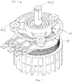
- Fig. 1 illustrates a motor 100 in accordance with one embodiment of the present invention.
- the motor 100 includes a stator 10 and a rotor 20.
- the stator 10 is received in the rotor 20, and the rotor 20 is rotatable relative to the stator 10.
- the motor 100 is an outer-rotor permanent magnet motor.
- the stator 10 includes a stator core 11, a winding bracket 12, stator windings 13, and a fixing bracket 14.
- the stator core 11 includes a plurality of stator teeth 111 preferably arranged at even or regular intervals. In at least one embodiment, the stator core 11 is exemplarily illustrated as including nine stator teeth 111. The number of the stator teeth 111 is not limited and, in other embodiments, the number of the stator teeth 111 may be adjusted in accordance with needs.
- the winding bracket 12 is configured to accommodate the stator core 11.
- the winding bracket 12 is formed by injecting plastic or rubber over an outer surface of the stator core 11.
- the number of the stator windings 13 is preferably equal to the number of the stator teeth 111, and each stator winding 13 is wound around a corresponding one of the stator teeth 111.
- One end of the fixing bracket 14 extends into the winding bracket 12 with the stator core 11 mounted therein, with the stator core 11 and the winding bracket 12 non-rotatable relative to the fixing bracket 14.
- the other end of the fixing bracket 14 is used for connection with an external element (not shown) so as to fix the stator 10 to the external element.
- An accommodating hole 141 is defined through a substantially central area of the fixing bracket 14 in an axial direction thereof.
- a bearing 15 is received in each of two ends of the accommodating holes 141.
- the stator 10 further includes a connecting plate 16 which is preferably formed so as to be or substantially be in the form of a half circular arc.
- the connecting plate 16 is connected to the winding bracket 12, and a plurality of terminals 17 is mounted to one side of the connecting plate 16.
- the number of the terminals 17 is three, each terminal 17 is used to electrically connect with one stator winding 13, and a wire of one phase leads out from each terminal 17. It will be appreciated, however, that the number of terminals may be dependent on the type of rotor to be produced.
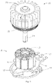
- the rotor 20 includes a yoke 21, a plurality of permanent magnets 22, an end cap 23, and a rotary shaft 24.
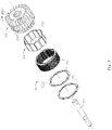
- the yoke 21 is preferably a shape of a hollow cylinder, and includes a plurality of annular first laminations 211 and an annular second lamination 212.
- the second lamination 212 is disposed at one end of the yoke 21.
- the first laminations 211 and the second lamination 212 may be silicon steel sheets or laminations of other soft magnetic material.
- the first and second laminations 211, 212 may be formed from the same material, or could be formed from different materials. In this embodiment, the number of the second lamination 212 is one, and each of the first laminations 211 has the same thickness as the second lamination 212.
- a plurality of second laminations 212 could be provided, however.
- the yoke 21 defines a plurality of first receiving slots 2111 through the first laminations 211 along the axial direction.
- Each first receiving slot 2111 has a preferably substantially rectangular cross section.
- each two adjacent first receiving slots 2111 are arranged preferably in a V-shape opened towards a center of the yoke 21, and the two adjacent first receiving slots 2111 arranged in the V-shape are in communication with each other.
- One side of each first lamination 211 forms a plurality of protrusions 2112.
- the number of the protrusions 2112 is six, and the six protrusions 2112 are arranged at even or regular intervals.
- the yoke 21 further defines a plurality of second receiving slots 2121 through the second lamination 212, corresponding to the first receiving slots 2111.
- Each second receiving slot 2121 preferably has a substantially rectangular cross section.
- each two adjacent second receiving slots 2121 are arranged in a V-shape opened towards a center of the yoke 21, and the two adjacent second receiving slots 2121 arranged in the V-shape are in communication with each other.
- the second lamination 212 defines through slots 2122 corresponding to the protrusions 2112 of the first lamination 211.
- the second receiving slot 2121 is less than the first receiving slot 2111 in width.
- the yoke 21 is formed by stacking the plurality of first laminations 211 and the second lamination 212. Adjacent first laminations 211 are fixed by means of engagement between the protrusions 2112 and the connecting grooves 2113.
- the second lamination 212 is disposed at one end of the yoke 21, and the through slots 2122 of the second lamination 212 engagingly receive the protrusions 2112 of one adjacent first lamination 211, so as to connect the second lamination 212 with the first lamination 211.
- each permanent magnet 22 is substantially in the form of a rectangular block.
- a width of the permanent magnet 22 is greater than a width of the second receiving slot 2121 and is substantially the same as a width of the first receiving slot 2111.
- each permanent magnet 22 abuts against the second lamination 212 after being inserted into the first receiving slot 2111 of the yoke 21 from an end of the yoke 21 opposite from the second lamination 212.
- the permanent magnet 22 does not pass through the second receiving slot 2121 to become disengaged from the yoke 21.
- the permanent magnet 22 may additionally or alternatively be fixed in the first receiving slot 2111 using a small amount of glue or other suitable adhesive substance. In this case, other yoke configurations could be considered for receiving permanent magnets of different sizes or shapes.
- the end cap 23 is, in the present embodiment, formed so as to include a bottom wall 231, a lateral wall 232, and preferably a plurality of vanes 233.
- the bottom wall 231 is substantially a circular plate.
- the lateral wall 232 is annular.
- Each vane 233 is substantially L-shaped, which has one end connected to the bottom wall 231 and the other end connected to the lateral wall 232.
- the vanes 233 are arranged at even intervals surrounding the bottom wall 231 so as to dissipate heat when rotating along with the rotor 20. In particular, when the motor 100 operates, the vanes 233 rotate along with the rotor 20 to produce airflow to dissipate heat of the motor 100.
- a through hole 2311 is defined through a substantially central area of the bottom wall 231.
- One end of the rotary shaft 24 is inserted into the through hole 2311 to connect to the end cap 23, and the other end of the rotary shaft 24 passes through the bearing 15 and the accommodating hole 141.
- An annular bracket 235 is further connected to an inner side of the lateral wall 232.
- the annular bracket 235 includes two annular plates 2351 and a plurality of fixing poles 2352 disposed between the two annular plates 2351.
- One annular plate 2351 of the annular bracket 235 is connected to the inner side of the lateral wall 232, and the other annular plate 2351 is disposed at an end of the lateral wall 232 away from the bottom wall 231 and disposed outside the lateral wall 232.
- the yoke 21 is disposed between the two annular plates 2351 of the annular bracket 235.
- the end of the yoke 21 where the second lamination 212 is disposed is immediately adjacent the annular plate 2351 outside the lateral wall 232.
- Each of the fixing poles 2352 extends through the yoke 21 and is disposed between the first receiving slots 2111 that are in communication with each other for further fixing the corresponding permanent magnets 22.
- the first laminations 211 and the second lamination 212 of the yoke 21 are sequentially stacked, and the plurality of permanent magnets 22 is received in the yoke 21.
- the yoke 21 and the rotary shaft 24 are placed in a corresponding mold, and the end cap 23 is formed by injecting plastic or rubber into the corresponding mold.
- Exemplary plastics materials might include acrylonitrile-butadiene-styrene, polyamides, polycarbonate, polypropylene, and/or polystyrene.
- the permanent magnets 22 are fixed in the yoke 21 by the formed end cap 23, and the yoke 21, the permanent magnets 22, the end cap 23 and the rotary shaft 24 are connected into a whole preferably by using such an injection molding process.
- the end cap 23 may further comprise a spoke, the spoke being configured to enhance the strength for supporting the vanes 233 of end cap 23.
- the spoke is fixed on the rotary shaft 24 before injection molding during fabrication and assembly of the rotor 20.
- a plurality of grooves 213 is defined in an inner surface of the yoke 21 along an axial direction thereof.
- the annular bracket 235 further includes a plurality of connecting poles 2353 corresponding to the grooves 213. Each of the connecting poles 2353 is received in a corresponding one of the grooves 213, for further fixing the yoke 21 as well as facilitating flow of plastic to form the end cap 23 during injection molding.
- the end cap 23 is formed by injection molding, and the yoke 21, the permanent magnets 22 and the rotary shaft 24 are connected into a whole or unitary configuration at the same time of forming the end cap 23.
- the traditional aluminum end cap is replaced with the molded end cap, which makes the rotor 20 easier to fabricate and have a lighter weight and lower cost.
- the receiving slots of the first lamination 211 and the second lamination 212 are different in width, such that the permanent magnets 22 can be more conveniently received in the yoke 21, which avoids the use of glues to fix the permanent magnets 22.
- the end cap 23 is formed by injection molding, the yoke 21 is directly fixed in the end cap 23, and thus the yoke 21, rotary shaft 24 and end cap 23 are integrally-formed, that is, there is a structural integration between the separate components. Therefore, additional fixing pins are no longer required to fix the yoke 21. Moreover, the number of the mold used during the fabrication of the yoke is not increased, which therefore does not increase the manufacturing burden.
- the motor 100 of this embodiment can be used in an electric tool such as in an electric saw 200.
- the electric saw 200 includes a saw blade 201.
- the motor 100 is used to drive the saw blade 201. It should be understood that the motor 100 can also be used in other electric tools, such as chainsaws, jigsaws, power drills, sanders, electric screwdrivers, for example.
Landscapes
- Engineering & Computer Science (AREA)
- Power Engineering (AREA)
- Life Sciences & Earth Sciences (AREA)
- Mechanical Engineering (AREA)
- Wood Science & Technology (AREA)
- Forests & Forestry (AREA)
- Physics & Mathematics (AREA)
- Thermal Sciences (AREA)
- Iron Core Of Rotating Electric Machines (AREA)
- Permanent Field Magnets Of Synchronous Machinery (AREA)
Claims (13)
- Außenrotor (20), Folgendes umfassend:ein Joch (21), das mehrere Aufnahmeschlitze (2111, 2121) entlang einer axialen Richtung des Jochs (21) definiert, wobei jeder der Aufnahmeschlitze (2111, 2121) einen Permanentmagneten (22) darin aufnimmt;eine Drehwelle (24), die sich in das Joch (21) erstreckt; undeine Endkappe (23), umfassend eine Bodenwand (231), eine Seitenwand (232) und eine ringförmige Halterung (235),wobei die Endkappe (23) auf dem Joch (21) und der Drehwelle (24) durch Spritzgießen von Kunststoff oder Kautschuk ausgebildet ist, wobei dadurch das Joch (21), die Drehwelle (24) und die Endkappe (23) einstückig ausgebildet werden, wobei die Permanentmagnete (22) zu dem Zeitpunkt des Spritzgießens in dem Joch (21) befestigt sind, und dadurch gekennzeichnet, dass die Drehwelle (24) mit der Bodenwand (231) verbunden ist, die ringförmige Halterung (235) mit einer Innenseite der Seitenwand (232) verbunden ist, und die ringförmige Halterung (235) zwei ringförmige Platten (2351) umfasst; und wobei die ringförmige Halterung (235) ferner mehrere Befestigungspole (2352) zum weiteren Befestigen der entsprechenden Permanentmagnete (22) umfasst, wobei die mehreren Befestigungspole (2352) zwischen den beiden ringförmigen Platten (2351) angeordnet und mit diesen verbunden sind, und die Befestigungspole (2352) sich durch das Joch (21) erstrecken und unmittelbar an die Permanentmagneten (22) angrenzen.
- Außenrotor (20) nach Anspruch 1, wobei das Joch (21) mehrere erste Blechungen (211) und eine zweite Blechung (212) umfasst, wobei das Joch (21) mehrere erste Aufnahmeschlitze (2111) durch die gesamten ersten Blechungen (211) entlang einer axialen Richtung des Jochs (21) definiert, jeder der ersten Aufnahmeschlitze (2111) einen Permanentmagneten (22) darin aufnimmt, ein Ende des Permanentmagneten (22) an der zweiten Blechung (212) anstößt, und der Permanentmagnet (22) zu dem Zeitpunkt des Spritzgießens in dem Joch (21) befestigt ist.
- Außenrotor (20) nach Anspruch 2, wobei das Joch (21) einen zweiten Aufnahmeschlitz (2121) durch die zweite Schicht (212) definiert, die jedem ersten Aufnahmeschlitz (2111) entspricht, und eine Breite des zweiten Aufnahmeschlitzes (2121) kleiner als eine Breite des Permanentmagneten (22) ist.
- Außenrotor (20) nach Anspruch 2, wobei mehrere Vorsprünge (2112) von einer Seite jeder ersten Blechung (211) vorspringen, die der zweiten Blechung (212) zugewandt ist, wobei die andere Seite der ersten Blechung (211) mehrere Verbindungsnuten (2113) ausbildet, die den Vorsprüngen (2112) entsprechen, und eine Seite der zweiten Blechung (212), die der ersten Blechung (211) zugewandt ist, mehrere Durchgangsschlitze (2122) definiert, die den Vorsprüngen (2112) der ersten Blechung (211) entsprechen.
- Außenrotor (20) nach Anspruch 1, wobei eine der beiden ringförmigen Platten (2351) mit der Innenseite der Seitenwand (232) verbunden ist und die andere ringförmige Platte (2351) an einem Ende der Seitenwand (232) von der Bodenwand (231) entfernt angeordnet ist und außerhalb der Seitenwand (232) angeordnet.
- Außenrotor (20) nach Anspruch 1, wobei mehrere Nuten (213) in einer Innenoberfläche des Jochs (21) entlang der axialen Richtung des Jochs (21) definiert sind, die ringförmige Halterung (235) mehrere Verbindungspole (2353) beinhaltet, die den Nuten (213) entsprechen, mehrere Verbindungspole (2353) zwischen den beiden ringförmigen Platten (2351) angeordnet und mit diesen verbunden sind, und jeder der Verbindungspole (2353) in einer entsprechenden Nute (213) aufgenommen ist.
- Außenrotor (20) nach Anspruch 1, wobei die Endkappe (23) ferner mehrere Schaufeln (233) umfasst, wobei ein Ende jeder Schaufel (233) mit der Bodenwand (231) verbunden ist, das andere Ende von jeder Schaufel (233) mit der Seitenwand (232) verbunden ist, eine Öffnung (234) zwischen angrenzenden Schaufeln (233) definiert ist, und ein Luftstrom, der durch Drehen der Schaufeln (233) erzeugt wird, über die Öffnung (234) in ein Inneres des Rotors (20) eintritt, um die Wärme des Rotors (20) abzuführen.
- Außenrotor (20) nach einem der vorhergehenden Ansprüche, wobei der Permanentmagnet (22) eine rechteckige Form aufweist.
- Außenrotor (20) nach einem der Ansprüche 1 bis 8, wobei die Endkappe (23) ferner eine Speiche umfasst, wobei die Speiche vor dem Spritzgießen an einem Ende der Drehwelle (24) befestigt wird, die mit der Endkappe (23) verbunden ist.
- Motor (100), Folgendes umfassend:einen Außenrotor (20) nach einem der vorhergehenden Ansprüche; undeinen Stator (10), umfassend einen Statorkern (11) und mehrere Statorwicklungen (13), wobei die Statorwicklungen (13) um den Statorkern (11) gewickelt sind, und der Statorkern (11) in dem Joch (21) aufgenommen ist.
- Elektrowerkzeug, umfassend einen Motor (100) nach Anspruch 10.
- Elektrowerkzeug nach Anspruch 11, wobei das Elektrowerkzeug eine elektrische Säge (200) ist, die ein Sägeblatt (201) umfasst, und der Motor (100) konfiguriert ist, um das Sägeblatt (201) anzutreiben.
- Verfahren zum Ausbilden eines Außenrotors (20), wobei das Verfahren die folgenden Schritte umfasst:a] Bereitstellen eines Jochs (21) und einer Drehwelle (24), die sich in das Joch (21) erstreckt, wobei das Joch (21) mehrere Aufnahmeschlitze (2111, 2121) entlang einer axialen Richtung des Jochs (21) definiert, wobei jeder der Aufnahmeschlitze (2111, 2121) einen Permanentmagneten (22) darin aufnimmt; undb] Ausbilden einer Endkappe (23) an dem Joch (21) und der Drehwelle (24) durch Spritzgießen von Kunststoff oder Kautschuk, und wobei dadurch das Joch (21), die Drehwelle (24) und die Endkappe (23) einstückig ausgebildet sind und die Permanentmagnete (22) in dem Joch befestigt sind, wobei die Endkappe (23) eine Bodenwand (231), eine Seitenwand (232) und eine ringförmigen Halterung (235) umfasst, und dadurch gekennzeichnet, dass die Drehwelle (24) mit der Bodenwand (231) verbunden ist, die ringförmige Halterung (235) mit einer Innenseite der Seitenwand (232) verbunden ist, die ringförmige Halterung (235) zwei ringförmige Platten (2351) umfasst, und wobei die ringförmige Halterung (235) ferner mehrere Befestigungspole (2352) zum weiteren Befestigen der entsprechenden Permanentmagnete (22) umfasst, mehrere Befestigungspole (2352) zwischen den beiden ringförmigen Platten (2351) angeordnet und mit diesen verbunden sind, und die Befestigungspole (2352) sich durch das Joch (21) erstrecken und unmittelbar an die Permanentmagnete (22) angrenzen.
Applications Claiming Priority (1)
| Application Number | Priority Date | Filing Date | Title |
|---|---|---|---|
| CN201610416651.8A CN107516958B (zh) | 2016-06-15 | 2016-06-15 | 转子、具有该转子的电机及电动工具 |
Publications (2)
| Publication Number | Publication Date |
|---|---|
| EP3258573A1 EP3258573A1 (de) | 2017-12-20 |
| EP3258573B1 true EP3258573B1 (de) | 2020-08-05 |
Family
ID=59067566
Family Applications (1)
| Application Number | Title | Priority Date | Filing Date |
|---|---|---|---|
| EP17176177.8A Active EP3258573B1 (de) | 2016-06-15 | 2017-06-15 | Rotor, motor und elektrowerkzeug mit verwendung davon |
Country Status (3)
| Country | Link |
|---|---|
| US (1) | US10673295B2 (de) |
| EP (1) | EP3258573B1 (de) |
| CN (1) | CN107516958B (de) |
Families Citing this family (12)
| Publication number | Priority date | Publication date | Assignee | Title |
|---|---|---|---|---|
| DE102015118695A1 (de) * | 2015-11-02 | 2017-05-04 | Ebm-Papst Mulfingen Gmbh & Co. Kg | Elektromotor mit verbesserter Kühlung |
| US11139722B2 (en) | 2018-03-02 | 2021-10-05 | Black & Decker Inc. | Motor having an external heat sink for a power tool |
| CN108631490B (zh) * | 2018-04-18 | 2019-12-24 | 江阴航源航空科技有限公司 | 一种电机用一体轴 |
| CN110556962A (zh) * | 2018-06-02 | 2019-12-10 | 龙海特尔福汽车电子研究所有限公司 | 一种润滑油泵电机 |
| TWI694662B (zh) * | 2018-07-23 | 2020-05-21 | 大陸商昆山廣興電子有限公司 | 馬達及其轉子 |
| US11437900B2 (en) | 2019-12-19 | 2022-09-06 | Black & Decker Inc. | Modular outer-rotor brushless motor for a power tool |
| US11757330B2 (en) | 2019-12-19 | 2023-09-12 | Black & Decker, Inc. | Canned outer-rotor brushless motor for a power tool |
| CN113497502A (zh) * | 2020-04-07 | 2021-10-12 | 广东德昌电机有限公司 | 电动工具、电机及其转子 |
| CN112366846A (zh) * | 2020-11-25 | 2021-02-12 | 东莞市鸿盈电子科技有限公司 | 一种新型的定子铁芯结构以及包括该结构的新型风扇电机 |
| US20220371068A1 (en) * | 2021-05-24 | 2022-11-24 | Metal Forming & Coining Corporation | Shaft assembly and method of producing the same |
| CN113644767A (zh) * | 2021-07-26 | 2021-11-12 | 深圳拓邦股份有限公司 | 一种电机及其转子组件 |
| US12176794B2 (en) | 2021-11-19 | 2024-12-24 | Black & Decker Inc. | Outer-rotor brushless motor for a power tool |
Family Cites Families (46)
| Publication number | Priority date | Publication date | Assignee | Title |
|---|---|---|---|---|
| JPS5395206A (en) * | 1977-02-01 | 1978-08-21 | Toshiba Corp | Stator core |
| FR2503950A1 (fr) | 1981-04-10 | 1982-10-15 | Goig Florencio | Perfectionnements apportes aux rotors notamment pour l'excitation d'alternateurs destines a l'allumage de moteurs pour vehicules a deux roues ou plus de deux roues |
| JPS60197134A (ja) * | 1984-03-21 | 1985-10-05 | Fanuc Ltd | 電動機及びその製造方法 |
| CA2047576C (en) * | 1991-04-03 | 2002-09-10 | Robert Alan Colwell | Draft inducer blower motor mounting and cooling construction |
| US5864191A (en) * | 1992-08-12 | 1999-01-26 | Seiko Epson Corporation | Efficient permanent magnet rotor for brushless motor |
| JPH08107640A (ja) * | 1994-10-03 | 1996-04-23 | Fanuc Ltd | 同期電動機のロータ |
| JP2002176755A (ja) * | 2000-12-11 | 2002-06-21 | Nippon Signal Co Ltd:The | Srモータおよび該モータを備えた転てつ機 |
| TW484617U (en) * | 2001-05-15 | 2002-04-21 | Shi-Tsai Chen | Pneumatic cover clip |
| JP2006014520A (ja) | 2004-06-28 | 2006-01-12 | Toshiba Corp | 回転電機の外転型回転子 |
| EP2092629A1 (de) * | 2006-12-12 | 2009-08-26 | TM4 Inc. | Permanentmagnet-rotorbaugruppe |
| JP2008240526A (ja) * | 2007-03-23 | 2008-10-09 | Nippon Densan Corp | モータ、送風ファン及びその製造方法 |
| US7923881B2 (en) * | 2007-05-04 | 2011-04-12 | A.O. Smith Corporation | Interior permanent magnet motor and rotor |
| EP2203968B1 (de) * | 2007-10-31 | 2011-09-07 | Ebm-Papst St. Georgen GmbH & CO. KG | Elektromotor |
| IT1392883B1 (it) * | 2008-09-03 | 2012-04-02 | Lenzi | Metodo per l'assemblaggio del rotore di una macchina elettrica rotante |
| DE102008064500B4 (de) * | 2008-12-23 | 2011-08-25 | Siemens Aktiengesellschaft, 80333 | Elektrische Maschine mit Abstützung der Wicklungsschaltung am Statorblechpaket |
| CN101615477B (zh) * | 2009-04-28 | 2011-04-06 | 浙江大学 | 双锥型盘式比例电磁铁 |
| BE1018595A3 (nl) * | 2009-09-10 | 2011-04-05 | Atlas Copco Airpower Nv | Werkwijze voor het assembleren van een rotor met permanente magneten, houder daarbij toegepast, en rotor verkregen door zulke werkwijze. |
| CN102111021B (zh) * | 2009-12-24 | 2013-12-18 | 中山大洋电机股份有限公司 | 一种滚筒电机定子结构 |
| CN102244423B (zh) * | 2010-05-13 | 2016-03-02 | 德昌电机(深圳)有限公司 | 电机 |
| CN201708673U (zh) * | 2010-07-01 | 2011-01-12 | 中山大洋电机制造有限公司 | 一种电机转子系统 |
| JP5399343B2 (ja) * | 2010-08-20 | 2014-01-29 | 株式会社三井ハイテック | 永久磁石の樹脂封止方法及びその方法で製造された積層鉄心 |
| CN201789350U (zh) * | 2010-08-31 | 2011-04-06 | 珠海格力电器股份有限公司 | 表面安装式永磁转子结构 |
| JP2013211931A (ja) * | 2010-10-04 | 2013-10-10 | Nippon Densan Corp | ロータ及びモータ |
| CN201947080U (zh) * | 2011-01-28 | 2011-08-24 | 中山大洋电机制造有限公司 | 一种无刷电机转子结构 |
| CN201966774U (zh) | 2011-03-09 | 2011-09-07 | 上海航天汽车机电股份有限公司舒航电器分公司 | 一种无刷电机外转子 |
| JP2013017337A (ja) | 2011-07-05 | 2013-01-24 | Nippon Densan Corp | モータおよびモータの製造方法 |
| US20140062243A1 (en) * | 2011-07-22 | 2014-03-06 | Ebm-Papst St. Georgen Gmbh & Co. Kg | Internal rotor motor |
| CN202309274U (zh) * | 2011-09-07 | 2012-07-04 | 佛山市威灵洗涤电机制造有限公司 | 带永磁转子的电机 |
| WO2013184961A1 (en) * | 2012-06-06 | 2013-12-12 | Nidec Motor Corporation | Motor having spoked outer rotor with spaced apart pole segments |
| US8994244B2 (en) * | 2012-08-01 | 2015-03-31 | Nidec Motor Corporation | Motor stator with reduced coil configuration |
| JP2014036554A (ja) * | 2012-08-10 | 2014-02-24 | Aisin Seiki Co Ltd | ロータヨークおよび該ロータヨークを用いたモータ |
| GB2505475B (en) * | 2012-08-31 | 2015-11-18 | Lappeenranta University Of Technology | Compressing a laminated stack in an electrical machine |
| CN104969444B (zh) * | 2012-08-31 | 2018-09-18 | 拉彭兰塔理工大学 | 电机 |
| CN202840836U (zh) * | 2012-08-31 | 2013-03-27 | 中山大洋电机股份有限公司 | 一种直流无刷电机结构 |
| CN103779984A (zh) * | 2012-10-23 | 2014-05-07 | 德昌电机(深圳)有限公司 | 电机 |
| JP6298237B2 (ja) * | 2013-02-22 | 2018-03-20 | 株式会社荏原製作所 | 真空ポンプ用モータロータ及びこれを備えるモータ並びに真空ポンプ |
| KR20140140185A (ko) * | 2013-05-28 | 2014-12-09 | 삼성전자주식회사 | 모터 |
| JP2015076956A (ja) * | 2013-10-08 | 2015-04-20 | 株式会社ジェイテクト | ロータコア及び磁石埋込型ロータ |
| CN203660853U (zh) * | 2013-12-20 | 2014-06-18 | 中山大洋电机制造有限公司 | 一种直流无刷电机 |
| JP2015154665A (ja) * | 2014-02-18 | 2015-08-24 | 株式会社ジェイテクト | ロータ及びロータの製造方法 |
| CN105099041A (zh) | 2014-04-22 | 2015-11-25 | 德昌电机(深圳)有限公司 | 无刷电机、无刷电机的外转子及其制造方法 |
| CN105490412B (zh) * | 2014-08-06 | 2019-07-09 | 德昌电机(深圳)有限公司 | 电机转子及应用其的无刷直流电机 |
| CN204012984U (zh) * | 2014-08-25 | 2014-12-10 | 湘潭电机股份有限公司 | 一种切向磁场永磁电机转子 |
| CN205029444U (zh) * | 2015-09-25 | 2016-02-10 | 深圳市实能高科动力有限公司 | 非晶铁合金式电机、定子组件和定子铁芯 |
| CN205123450U (zh) * | 2015-10-22 | 2016-03-30 | 珠海格力节能环保制冷技术研究中心有限公司 | 磁瓦骨架 |
| CN105576927B (zh) * | 2016-03-09 | 2019-01-15 | 深圳小象电动科技有限公司 | 定子浸油散热且转子内置式的盘式电动机 |
-
2016
- 2016-06-15 CN CN201610416651.8A patent/CN107516958B/zh active Active
-
2017
- 2017-06-14 US US15/623,017 patent/US10673295B2/en active Active
- 2017-06-15 EP EP17176177.8A patent/EP3258573B1/de active Active
Non-Patent Citations (1)
| Title |
|---|
| None * |
Also Published As
| Publication number | Publication date |
|---|---|
| US20170366061A1 (en) | 2017-12-21 |
| CN107516958A (zh) | 2017-12-26 |
| US10673295B2 (en) | 2020-06-02 |
| EP3258573A1 (de) | 2017-12-20 |
| CN107516958B (zh) | 2020-12-01 |
Similar Documents
| Publication | Publication Date | Title |
|---|---|---|
| EP3258573A1 (de) | Rotor, motor und elektrowerkzeug mit verwendung davon | |
| EP1536543B1 (de) | Rotor für einen permanentmagnetmotor des typs mit externem rotor | |
| JP4561770B2 (ja) | アキシャルギャップ型回転電機及びその製造方法 | |
| JP5587544B2 (ja) | 永久磁石モータ | |
| US20030057796A1 (en) | Modularized stator | |
| US10862353B2 (en) | Axial gap motor rotor and axial gap motor | |
| EP3503362B1 (de) | Rotorauswuchtung/-fixierung durch spritzgiessen oder formpressen | |
| EP3297130B1 (de) | Rotorlaminierungsanordnung | |
| CN100533917C (zh) | 外转式永磁铁电机的转子 | |
| CN107465284B (zh) | 转子及具有该转子的电机、电动工具 | |
| WO2005117235A1 (en) | Rotor for an electric machine | |
| EP2228481B1 (de) | Waschmaschine mit einem direkten Antriebsmotorsystem | |
| EP1942571A1 (de) | Motor mit zwei rotoren und vorrichtung damit | |
| EP3923447A1 (de) | Elektrowerkzeug | |
| JP2016201936A (ja) | 回転電機のロータ | |
| CN103516063B (zh) | 马达组装结构 | |
| US7612481B2 (en) | Rotor with a cover plate for securing a magnet in the rotor | |
| WO2004030187A1 (en) | A flat board type brushless dc motor | |
| KR20200114258A (ko) | 모터 | |
| JP2020141442A (ja) | ブラシレスモータおよび電動送風機 | |
| EP3276793A1 (de) | Rotoranordnung, insbesondere für einen elektromotor vom ipm-pmasr-typ und elektromotor mit besagter rotoranordnung | |
| EP3923454A1 (de) | Elektrowerkzeug und motor | |
| JP2005269831A (ja) | ブラシレスdcモータ | |
| US20240413683A1 (en) | Series connection of magnet pockets to improve and speed up the filling and ventilation process | |
| JP2016127681A (ja) | 回転電機のステータ |
Legal Events
| Date | Code | Title | Description |
|---|---|---|---|
| PUAI | Public reference made under article 153(3) epc to a published international application that has entered the european phase |
Free format text: ORIGINAL CODE: 0009012 |
|
| STAA | Information on the status of an ep patent application or granted ep patent |
Free format text: STATUS: THE APPLICATION HAS BEEN PUBLISHED |
|
| AK | Designated contracting states |
Kind code of ref document: A1 Designated state(s): AL AT BE BG CH CY CZ DE DK EE ES FI FR GB GR HR HU IE IS IT LI LT LU LV MC MK MT NL NO PL PT RO RS SE SI SK SM TR |
|
| AX | Request for extension of the european patent |
Extension state: BA ME |
|
| STAA | Information on the status of an ep patent application or granted ep patent |
Free format text: STATUS: REQUEST FOR EXAMINATION WAS MADE |
|
| 17P | Request for examination filed |
Effective date: 20180613 |
|
| RBV | Designated contracting states (corrected) |
Designated state(s): AL AT BE BG CH CY CZ DE DK EE ES FI FR GB GR HR HU IE IS IT LI LT LU LV MC MK MT NL NO PL PT RO RS SE SI SK SM TR |
|
| STAA | Information on the status of an ep patent application or granted ep patent |
Free format text: STATUS: EXAMINATION IS IN PROGRESS |
|
| RAP1 | Party data changed (applicant data changed or rights of an application transferred) |
Owner name: JOHNSON ELECTRIC INTERNATIONAL AG |
|
| 17Q | First examination report despatched |
Effective date: 20190329 |
|
| GRAP | Despatch of communication of intention to grant a patent |
Free format text: ORIGINAL CODE: EPIDOSNIGR1 |
|
| STAA | Information on the status of an ep patent application or granted ep patent |
Free format text: STATUS: GRANT OF PATENT IS INTENDED |
|
| INTG | Intention to grant announced |
Effective date: 20200302 |
|
| GRAS | Grant fee paid |
Free format text: ORIGINAL CODE: EPIDOSNIGR3 |
|
| GRAA | (expected) grant |
Free format text: ORIGINAL CODE: 0009210 |
|
| STAA | Information on the status of an ep patent application or granted ep patent |
Free format text: STATUS: THE PATENT HAS BEEN GRANTED |
|
| AK | Designated contracting states |
Kind code of ref document: B1 Designated state(s): AL AT BE BG CH CY CZ DE DK EE ES FI FR GB GR HR HU IE IS IT LI LT LU LV MC MK MT NL NO PL PT RO RS SE SI SK SM TR |
|
| REG | Reference to a national code |
Ref country code: GB Ref legal event code: FG4D |
|
| REG | Reference to a national code |
Ref country code: CH Ref legal event code: EP |
|
| REG | Reference to a national code |
Ref country code: AT Ref legal event code: REF Ref document number: 1300097 Country of ref document: AT Kind code of ref document: T Effective date: 20200815 |
|
| REG | Reference to a national code |
Ref country code: DE Ref legal event code: R096 Ref document number: 602017020878 Country of ref document: DE |
|
| REG | Reference to a national code |
Ref country code: IE Ref legal event code: FG4D |
|
| REG | Reference to a national code |
Ref country code: SE Ref legal event code: TRGR |
|
| REG | Reference to a national code |
Ref country code: LT Ref legal event code: MG4D |
|
| REG | Reference to a national code |
Ref country code: NL Ref legal event code: MP Effective date: 20200805 |
|
| REG | Reference to a national code |
Ref country code: AT Ref legal event code: MK05 Ref document number: 1300097 Country of ref document: AT Kind code of ref document: T Effective date: 20200805 |
|
| PG25 | Lapsed in a contracting state [announced via postgrant information from national office to epo] |
Ref country code: HR Free format text: LAPSE BECAUSE OF FAILURE TO SUBMIT A TRANSLATION OF THE DESCRIPTION OR TO PAY THE FEE WITHIN THE PRESCRIBED TIME-LIMIT Effective date: 20200805 Ref country code: AT Free format text: LAPSE BECAUSE OF FAILURE TO SUBMIT A TRANSLATION OF THE DESCRIPTION OR TO PAY THE FEE WITHIN THE PRESCRIBED TIME-LIMIT Effective date: 20200805 Ref country code: NO Free format text: LAPSE BECAUSE OF FAILURE TO SUBMIT A TRANSLATION OF THE DESCRIPTION OR TO PAY THE FEE WITHIN THE PRESCRIBED TIME-LIMIT Effective date: 20201105 Ref country code: FI Free format text: LAPSE BECAUSE OF FAILURE TO SUBMIT A TRANSLATION OF THE DESCRIPTION OR TO PAY THE FEE WITHIN THE PRESCRIBED TIME-LIMIT Effective date: 20200805 Ref country code: GR Free format text: LAPSE BECAUSE OF FAILURE TO SUBMIT A TRANSLATION OF THE DESCRIPTION OR TO PAY THE FEE WITHIN THE PRESCRIBED TIME-LIMIT Effective date: 20201106 Ref country code: PT Free format text: LAPSE BECAUSE OF FAILURE TO SUBMIT A TRANSLATION OF THE DESCRIPTION OR TO PAY THE FEE WITHIN THE PRESCRIBED TIME-LIMIT Effective date: 20201207 Ref country code: BG Free format text: LAPSE BECAUSE OF FAILURE TO SUBMIT A TRANSLATION OF THE DESCRIPTION OR TO PAY THE FEE WITHIN THE PRESCRIBED TIME-LIMIT Effective date: 20201105 Ref country code: ES Free format text: LAPSE BECAUSE OF FAILURE TO SUBMIT A TRANSLATION OF THE DESCRIPTION OR TO PAY THE FEE WITHIN THE PRESCRIBED TIME-LIMIT Effective date: 20200805 Ref country code: LT Free format text: LAPSE BECAUSE OF FAILURE TO SUBMIT A TRANSLATION OF THE DESCRIPTION OR TO PAY THE FEE WITHIN THE PRESCRIBED TIME-LIMIT Effective date: 20200805 |
|
| PG25 | Lapsed in a contracting state [announced via postgrant information from national office to epo] |
Ref country code: RS Free format text: LAPSE BECAUSE OF FAILURE TO SUBMIT A TRANSLATION OF THE DESCRIPTION OR TO PAY THE FEE WITHIN THE PRESCRIBED TIME-LIMIT Effective date: 20200805 Ref country code: LV Free format text: LAPSE BECAUSE OF FAILURE TO SUBMIT A TRANSLATION OF THE DESCRIPTION OR TO PAY THE FEE WITHIN THE PRESCRIBED TIME-LIMIT Effective date: 20200805 Ref country code: NL Free format text: LAPSE BECAUSE OF FAILURE TO SUBMIT A TRANSLATION OF THE DESCRIPTION OR TO PAY THE FEE WITHIN THE PRESCRIBED TIME-LIMIT Effective date: 20200805 Ref country code: PL Free format text: LAPSE BECAUSE OF FAILURE TO SUBMIT A TRANSLATION OF THE DESCRIPTION OR TO PAY THE FEE WITHIN THE PRESCRIBED TIME-LIMIT Effective date: 20200805 Ref country code: IS Free format text: LAPSE BECAUSE OF FAILURE TO SUBMIT A TRANSLATION OF THE DESCRIPTION OR TO PAY THE FEE WITHIN THE PRESCRIBED TIME-LIMIT Effective date: 20201205 |
|
| PG25 | Lapsed in a contracting state [announced via postgrant information from national office to epo] |
Ref country code: CZ Free format text: LAPSE BECAUSE OF FAILURE TO SUBMIT A TRANSLATION OF THE DESCRIPTION OR TO PAY THE FEE WITHIN THE PRESCRIBED TIME-LIMIT Effective date: 20200805 Ref country code: DK Free format text: LAPSE BECAUSE OF FAILURE TO SUBMIT A TRANSLATION OF THE DESCRIPTION OR TO PAY THE FEE WITHIN THE PRESCRIBED TIME-LIMIT Effective date: 20200805 Ref country code: RO Free format text: LAPSE BECAUSE OF FAILURE TO SUBMIT A TRANSLATION OF THE DESCRIPTION OR TO PAY THE FEE WITHIN THE PRESCRIBED TIME-LIMIT Effective date: 20200805 Ref country code: EE Free format text: LAPSE BECAUSE OF FAILURE TO SUBMIT A TRANSLATION OF THE DESCRIPTION OR TO PAY THE FEE WITHIN THE PRESCRIBED TIME-LIMIT Effective date: 20200805 Ref country code: SM Free format text: LAPSE BECAUSE OF FAILURE TO SUBMIT A TRANSLATION OF THE DESCRIPTION OR TO PAY THE FEE WITHIN THE PRESCRIBED TIME-LIMIT Effective date: 20200805 |
|
| REG | Reference to a national code |
Ref country code: DE Ref legal event code: R097 Ref document number: 602017020878 Country of ref document: DE |
|
| PG25 | Lapsed in a contracting state [announced via postgrant information from national office to epo] |
Ref country code: AL Free format text: LAPSE BECAUSE OF FAILURE TO SUBMIT A TRANSLATION OF THE DESCRIPTION OR TO PAY THE FEE WITHIN THE PRESCRIBED TIME-LIMIT Effective date: 20200805 |
|
| PLBE | No opposition filed within time limit |
Free format text: ORIGINAL CODE: 0009261 |
|
| STAA | Information on the status of an ep patent application or granted ep patent |
Free format text: STATUS: NO OPPOSITION FILED WITHIN TIME LIMIT |
|
| PG25 | Lapsed in a contracting state [announced via postgrant information from national office to epo] |
Ref country code: SK Free format text: LAPSE BECAUSE OF FAILURE TO SUBMIT A TRANSLATION OF THE DESCRIPTION OR TO PAY THE FEE WITHIN THE PRESCRIBED TIME-LIMIT Effective date: 20200805 |
|
| 26N | No opposition filed |
Effective date: 20210507 |
|
| PG25 | Lapsed in a contracting state [announced via postgrant information from national office to epo] |
Ref country code: IT Free format text: LAPSE BECAUSE OF FAILURE TO SUBMIT A TRANSLATION OF THE DESCRIPTION OR TO PAY THE FEE WITHIN THE PRESCRIBED TIME-LIMIT Effective date: 20200805 |
|
| PG25 | Lapsed in a contracting state [announced via postgrant information from national office to epo] |
Ref country code: SI Free format text: LAPSE BECAUSE OF FAILURE TO SUBMIT A TRANSLATION OF THE DESCRIPTION OR TO PAY THE FEE WITHIN THE PRESCRIBED TIME-LIMIT Effective date: 20200805 |
|
| PG25 | Lapsed in a contracting state [announced via postgrant information from national office to epo] |
Ref country code: MC Free format text: LAPSE BECAUSE OF FAILURE TO SUBMIT A TRANSLATION OF THE DESCRIPTION OR TO PAY THE FEE WITHIN THE PRESCRIBED TIME-LIMIT Effective date: 20200805 |
|
| REG | Reference to a national code |
Ref country code: CH Ref legal event code: PL |
|
| GBPC | Gb: european patent ceased through non-payment of renewal fee |
Effective date: 20210615 |
|
| REG | Reference to a national code |
Ref country code: BE Ref legal event code: MM Effective date: 20210630 |
|
| PG25 | Lapsed in a contracting state [announced via postgrant information from national office to epo] |
Ref country code: LU Free format text: LAPSE BECAUSE OF NON-PAYMENT OF DUE FEES Effective date: 20210615 |
|
| PG25 | Lapsed in a contracting state [announced via postgrant information from national office to epo] |
Ref country code: LI Free format text: LAPSE BECAUSE OF NON-PAYMENT OF DUE FEES Effective date: 20210630 Ref country code: IE Free format text: LAPSE BECAUSE OF NON-PAYMENT OF DUE FEES Effective date: 20210615 Ref country code: GB Free format text: LAPSE BECAUSE OF NON-PAYMENT OF DUE FEES Effective date: 20210615 Ref country code: CH Free format text: LAPSE BECAUSE OF NON-PAYMENT OF DUE FEES Effective date: 20210630 |
|
| PG25 | Lapsed in a contracting state [announced via postgrant information from national office to epo] |
Ref country code: FR Free format text: LAPSE BECAUSE OF NON-PAYMENT OF DUE FEES Effective date: 20210630 |
|
| PG25 | Lapsed in a contracting state [announced via postgrant information from national office to epo] |
Ref country code: BE Free format text: LAPSE BECAUSE OF NON-PAYMENT OF DUE FEES Effective date: 20210630 |
|
| PG25 | Lapsed in a contracting state [announced via postgrant information from national office to epo] |
Ref country code: HU Free format text: LAPSE BECAUSE OF FAILURE TO SUBMIT A TRANSLATION OF THE DESCRIPTION OR TO PAY THE FEE WITHIN THE PRESCRIBED TIME-LIMIT; INVALID AB INITIO Effective date: 20170615 |
|
| PG25 | Lapsed in a contracting state [announced via postgrant information from national office to epo] |
Ref country code: CY Free format text: LAPSE BECAUSE OF FAILURE TO SUBMIT A TRANSLATION OF THE DESCRIPTION OR TO PAY THE FEE WITHIN THE PRESCRIBED TIME-LIMIT Effective date: 20200805 |
|
| REG | Reference to a national code |
Ref country code: DE Ref legal event code: R084 Ref document number: 602017020878 Country of ref document: DE |
|
| P01 | Opt-out of the competence of the unified patent court (upc) registered |
Effective date: 20230628 |
|
| PG25 | Lapsed in a contracting state [announced via postgrant information from national office to epo] |
Ref country code: MK Free format text: LAPSE BECAUSE OF FAILURE TO SUBMIT A TRANSLATION OF THE DESCRIPTION OR TO PAY THE FEE WITHIN THE PRESCRIBED TIME-LIMIT Effective date: 20200805 |
|
| PG25 | Lapsed in a contracting state [announced via postgrant information from national office to epo] |
Ref country code: TR Free format text: LAPSE BECAUSE OF FAILURE TO SUBMIT A TRANSLATION OF THE DESCRIPTION OR TO PAY THE FEE WITHIN THE PRESCRIBED TIME-LIMIT Effective date: 20200805 |
|
| PG25 | Lapsed in a contracting state [announced via postgrant information from national office to epo] |
Ref country code: MT Free format text: LAPSE BECAUSE OF FAILURE TO SUBMIT A TRANSLATION OF THE DESCRIPTION OR TO PAY THE FEE WITHIN THE PRESCRIBED TIME-LIMIT Effective date: 20200805 |
|
| PGFP | Annual fee paid to national office [announced via postgrant information from national office to epo] |
Ref country code: DE Payment date: 20250626 Year of fee payment: 9 |
|
| PGFP | Annual fee paid to national office [announced via postgrant information from national office to epo] |
Ref country code: SE Payment date: 20250619 Year of fee payment: 9 |