EP3258552B1 - Dispositif de fabrication d'un composant à partir d'au moins deux composants fabriqués en série - Google Patents
Dispositif de fabrication d'un composant à partir d'au moins deux composants fabriqués en série Download PDFInfo
- Publication number
- EP3258552B1 EP3258552B1 EP17176006.9A EP17176006A EP3258552B1 EP 3258552 B1 EP3258552 B1 EP 3258552B1 EP 17176006 A EP17176006 A EP 17176006A EP 3258552 B1 EP3258552 B1 EP 3258552B1
- Authority
- EP
- European Patent Office
- Prior art keywords
- transport
- component parts
- workpiece carrier
- assembly devices
- along
- Prior art date
- Legal status (The legal status is an assumption and is not a legal conclusion. Google has not performed a legal analysis and makes no representation as to the accuracy of the status listed.)
- Not-in-force
Links
Images


Classifications
-
- B—PERFORMING OPERATIONS; TRANSPORTING
- B23—MACHINE TOOLS; METAL-WORKING NOT OTHERWISE PROVIDED FOR
- B23P—METAL-WORKING NOT OTHERWISE PROVIDED FOR; COMBINED OPERATIONS; UNIVERSAL MACHINE TOOLS
- B23P21/00—Machines for assembling a multiplicity of different parts to compose units, with or without preceding or subsequent working of such parts, e.g. with program control
- B23P21/004—Machines for assembling a multiplicity of different parts to compose units, with or without preceding or subsequent working of such parts, e.g. with program control the units passing two or more work-stations whilst being composed
-
- H—ELECTRICITY
- H01—ELECTRIC ELEMENTS
- H01R—ELECTRICALLY-CONDUCTIVE CONNECTIONS; STRUCTURAL ASSOCIATIONS OF A PLURALITY OF MUTUALLY-INSULATED ELECTRICAL CONNECTING ELEMENTS; COUPLING DEVICES; CURRENT COLLECTORS
- H01R13/00—Details of coupling devices of the kinds covered by groups H01R12/70 or H01R24/00 - H01R33/00
- H01R13/02—Contact members
- H01R13/22—Contacts for co-operating by abutting
- H01R13/24—Contacts for co-operating by abutting resilient; resiliently-mounted
- H01R13/2407—Contacts for co-operating by abutting resilient; resiliently-mounted characterized by the resilient means
-
- H—ELECTRICITY
- H01—ELECTRIC ELEMENTS
- H01R—ELECTRICALLY-CONDUCTIVE CONNECTIONS; STRUCTURAL ASSOCIATIONS OF A PLURALITY OF MUTUALLY-INSULATED ELECTRICAL CONNECTING ELEMENTS; COUPLING DEVICES; CURRENT COLLECTORS
- H01R43/00—Apparatus or processes specially adapted for manufacturing, assembling, maintaining, or repairing of line connectors or current collectors or for joining electric conductors
- H01R43/20—Apparatus or processes specially adapted for manufacturing, assembling, maintaining, or repairing of line connectors or current collectors or for joining electric conductors for assembling or disassembling contact members with insulating base, case or sleeve
-
- H—ELECTRICITY
- H01—ELECTRIC ELEMENTS
- H01R—ELECTRICALLY-CONDUCTIVE CONNECTIONS; STRUCTURAL ASSOCIATIONS OF A PLURALITY OF MUTUALLY-INSULATED ELECTRICAL CONNECTING ELEMENTS; COUPLING DEVICES; CURRENT COLLECTORS
- H01R43/00—Apparatus or processes specially adapted for manufacturing, assembling, maintaining, or repairing of line connectors or current collectors or for joining electric conductors
- H01R43/16—Apparatus or processes specially adapted for manufacturing, assembling, maintaining, or repairing of line connectors or current collectors or for joining electric conductors for manufacturing contact members, e.g. by punching and by bending
Definitions
- the invention relates to a device with the features of the preamble of claim 1 or the features of the preamble of claim 2 for the production of components from in each case at least two component components in series production.
- Devices for producing a component from component components in series production which include an assembly device for joining first component components and second component components and also have transport devices for feeding the first component component and the second component component to the assembly device.
- the component components are usually supplied in a transport cycle or machine cycle, so that in each case a first component component is moved on a workpiece carrier to the assembly device and the assigned second component component arrives there essentially synchronously, so that in the corresponding machine cycle the second component component with the first component component by means of the Mounting device can be connected.
- this component assembly is transported away from the area of the assembly device by means of the relevant transport device in order to make space for component components that are to be connected to one another.
- components are often multi-component-free components, such as in insulating nests embedded electrical switching contact elements or SMD components (s urface m ounted D evices) for electronic devices or like that.
- the component components can be component components made of different materials and / or different shapes and / or different dimensions.
- An example could be an electrical contact in a plastic holder, wherein the plastic holder could represent a first component component and the electrical contact could represent a second component component in the sense explained above.
- Such multi-component small components are often produced in large numbers in high-speed series production, namely especially when there is a need for large quantities of such components and high cost pressure with regard to their production.
- a generic device with the features of the preamble of claim 1 and the preamble of claim 2 is from the U.S. 3,561,114 A. known.
- the U.S. 3,561,114 A. discloses a device in which the first transport device is set up to move equidistant workpiece carrier sections circumferentially along a closed endless path as the first transport path, clocked and intermittently with a given step size along the first transport path to various work stations arranged along a linear section of the first transport path.
- These workstations include, in particular, two assembly devices on which both sides of a coil are fitted with connections one after the other, so that each coil can be connected to both assembly devices U.S. 3,561,114 A. is processed.
- the object of the present invention is to enable an increase in the productivity of a generic device for producing components from at least two component components, each of which is Assembly devices that manufacture components.
- a device with the features of claim 1 is proposed for continuous transport, and according to the second aspect of the invention, a device with the features of claim 2 for intermittent transport.
- first component components can be assigned a different number of second component elements for common connection.
- One approach of the invention is to position n assembly devices, i.e. at least two assembly devices, along the first transport path, these assembly devices having the task of assembling first component components and second component components, preferably at the same time, to form a respective composite, and the assembly devices being one and the same first transport device are supplied with first component components at the same time as the provision times of the first transport device.
- n assembly devices i.e. at least two assembly devices
- second component components preferably at the same time
- the first transport device can be set up to transport first component components in groups to the assembly devices, so that at the times when the first transport device is made available, a respective group of first component components on each of the assembly devices for essentially simultaneous processing and / or is ready to be taken over by the assembly devices.
- the second transport device provides a respective number of second component components on the assembly devices at the times at which the first transport device is made available ready, which corresponds to the need for second component components for assembling with the first component components on the assembly devices.
- the assembly devices are then to be operated in such a way that they can simultaneously connect component components of the respective group of first component components with correspondingly assigned second component components at or between the provision times of the first transport device. In this way, too, the productivity of the device for producing a component from at least two component components in series production can be increased.
- the first transport path is a closed endless path or loop, the first transport device comprising workpiece carrier sections following at least approximately equidistantly along the first transport path and being configured to move them circumferentially along the first transport path, and wherein the workpiece carrier sections are individually configured to each Pick up the first component component or possibly a respective group of first component components for transport and move it along the first transport path in accordance with the transport movement of the first transport device, the distances between the positions of the assembly devices along the first transport path being the distance at least in a certain section of the first transport path x between similar locations, preferably the centers of two directly successive workpiece carrier sections along the first transport path or correspond to an integer multiple thereof, so that a feed movement of the workpiece carrier sections coordinated with the distance x by the first transport device can be selected in order to supply all n assembly devices with a first component component or, if necessary, a group of first component components at each provision time. In this way, the transport and transport control effort in the supply of the first Component components to the assembly devices are kept low.
- the workpiece carrier sections are preferably holders that are shaped so that they can accommodate first component components or possibly groups of first component components in a desired relative orientation for transport along the first transport path, and which are arranged equidistantly in series on an endless belt which is moved circumferentially by the first transport device along the first transport path in order to always provide a respective workpiece carrier section with a first component component or possibly a group of first component components at the times of provision on the assembly devices at the same time.
- the first transport device can be set up to move the first component components or the workpiece carrier sections continuously, preferably at a constant speed, or discontinuously or intermittently.
- a device according to the invention can also be set up for the optional continuous or discontinuous transport operation of the first transport device.
- the first transport device advances the workpiece carrier sections continuously at a feed speed V along the first transport path, the feed speed V and the distances (D) between the positions of the assembly devices along the first transport path being coordinated with one another that during operation of the first transport device - at least after a start-up phase - a respective workpiece carrier section is available on all assembly devices at the times of provision of the first transport device, so that when the first transport device rotates all workpiece carrier sections serially at the times of provision at one relevant assembly device are provided, wherein no workpiece carrier portion is provided on more than one assembly device.
- the assembly devices are thus placed at selected positions along the first transport path, so that with a complete rotation of the workpiece carrier sections along the first transport path designed as an endless path and with a correspondingly selected feed rate during the transport movement of the first transport device, each workpiece carrier section only once to provide first component components on an assembly device is available at a relevant provision time. At the other times of readiness, the workpiece carrier sections are located outside the assignment area of the assembly devices during the cycle.
- first transport device operated for continuous transport various modes of operation of the assembly devices come into question.
- first component components remain in their respective workpiece carrier sections during the process of joining the first and second component components and that the assembly devices move the workpiece carrier sections over a short distance during their assembly processes of assembling the component components follow the time interval required for the assembly process.
- first component components are briefly and temporarily separated from the workpiece carrier sections for the purpose of joining the first and second component components, all this within a short time interval that is required for the assembly process and in which the workpiece carrier section has been assigned to the relevant assembly device since the last time it was made available.
- transfer means must be set up to include a relevant first To remove component components from their workpiece carrier section at the time of preparation and to return them to the workpiece carrier section after processing by the assembly device after the latter has been moved on by a small section along the first transport path.
- the device can be operated with discontinuous operation of the first transport device.
- This device comprises a certain number n (greater than 1) of assembly devices for assembling first component components and second component components to form components, a first transport device for the clocked, intermittent transport of first component components to the assembly devices along a first transport path designed as a closed endless path, a second transport device for transport second component components to the assembly devices, wherein the first transport device is set up to transport at least one respective first component component to each assembly device in the transport cycle, so that at least one first component component on each assembly device for essentially simultaneous processing during stop times of the intermittent transport movement of the first transport device is available by the assembly devices, wherein the second transport device is set up at the stop times to provide the intermittent transport movement of the first transport device with a respective number of second component components on the assembly devices, which corresponds to the need for second component components for joining with the first component components on the assembly devices.
- the first transport device of this device is set up to move the workpiece carrier sections clocked intermittently with a step size S along the first transport path, the distances (D) between the positions of the assembly devices along the first transport path being coordinated with one another so that During operation of the first transport device - at least after a start-up phase - a respective workpiece carrier section is available at all assembly devices in the stop times of the intermittent transport movement corresponding to the provision times of the first transport device, so that when the first transport device rotates, all workpiece carrier sections serially in the stop times of the intermittent Transport movement are provided on a relevant assembly device, wherein no workpiece carrier portion is provided on more than one assembly device.
- the stop positions along the first transport path can also be numbered periodically, the number of periods corresponding to the number of groups of workpiece carrier sections. Workpiece carrier sections with a certain number only come to a stop at the stop positions with the same number along the first transport path. This applies to all workpiece carrier sections.
- the n assembly devices are distributed in their assignment to stop positions of the workpiece carrier sections along the first transport path via stop positions with the numbers 1 to n, with one assembly device for each stop position number. If a mounting device is assigned to a stop position with a specific stop position number in a period, no mounting device is assigned to the same stop position number in another period.
- the total number of stop positions along the first Transport distance should be divisible by n without a remainder.
- the first transport path has at least one linear section, the assembly devices preferably being positioned on the linear section of the first transport path in association with relevant stop positions of the workpiece carrier sections.
- the first transport path is formed as an oval in plan projection from two semicircular arcs connected to one another by linear sections.
- the linear sections can then be used very well for a space-optimized positioning of the assembly devices on the one hand and of transfer devices for transferring first component components to workpiece carrier sections of the first transport device on the other hand, as well as for the favorable positioning of discharge devices for discharging components from the workpiece carrier sections and for discharging the components from the first Transport facility can be used.
- the second component components are tiny and / or filigree stamped parts.
- These holding strips and the second component components arranged thereon are preferably a punched strip in which the holding strip and the second component components are cohesively connected.
- the holding strip is remnants of a raw material strip that are cohesively connected to the second component components and that has been subjected to a punching process by means of a punching press in order to form the second component components.
- a punch press can be connected directly or indirectly upstream of the device for producing a component from at least two component components in series production, so that the punch strip leaving the punch press is fed directly to the device according to the invention.
- a forming device can also be interposed between such a punch press and the device according to the invention, for example in order to subject the second component components to a bending process; or a welding station to weld on a contact.
- Such devices can optionally also be integrated into the device according to the invention.
- the second transport device is set up to intermittently move the retaining strip with the second component components arranged thereon, the step cycle of the second transport device and the step cycle of the first transport device being coordinated, in particular synchronized, with one another.
- the subsequent density of the second component components on the holding strip is preferably selected so that after each step the respective required amount of second component components for further processing on the assembly devices is pending.
- the assembly devices are each assigned a device for separating the provided second component components from their holding strips. The separated second component components can then be fed to the workpiece carrier sections of the first transport device by means of transfer devices or automatic placement machines of the assembly devices in order to be combined there with the provided first component components.
- the holding strip has a longitudinal division in such a way that it has two separate edge strip sections running in the longitudinal direction of the strip, the distance between them being transverse to the longitudinal direction of the strip Is essentially constant and each of which forms a retaining strip edge section from which respective second component components protrude in the longitudinal direction of the strip successively with free spaces in between transversely to the longitudinal direction of the strip, in such a way that the second component components of one retaining strip protrude into the free spaces of the component components of the other retaining strip.
- such a solution enables a greater density of consecutive second component components on the holding strip with very little waste, for example during punching or another material separation process on a relevant raw material strip.
- At least one transfer device is assigned to the first transport device, which is set up to feed first component components to the workpiece carrier sections of the first transport device, so that each workpiece carrier section can receive one by means of the first Transport device to be transported to the assembly devices receives the respective number of first component components.
- a discharge device can also be provided for discharging assembled components from the workpiece carrier sections and the first transport path.
- a first transport device 2 is represented by an endless belt 4 in the form of a closed oval loop with workpiece carrier sections 6 arranged thereon.
- the endless belt 4 is driven intermittently and clockwise circumferentially along an oval first transport path 8 according to the arrow 10 by means of drive means (not shown) of the first transport device 2.
- the workpiece carrier sections 6 are arranged essentially equidistantly one after the other at distances x from the workpiece carrier section center to the workpiece carrier section center on the endless belt 4 and are designed to receive two contact housings 12 connected in pairs as first component components 12, these Contact housing pairs are supplied from transfer devices 14, 15 from a relevant magazine.
- the two transfer devices 14, 15 are arranged so as to be adapted to the distance x that they can simultaneously equip two consecutive workpiece carrier sections 6 with contact housing pairs 12, 12 during the stop times of the intermittent transport movement of the first transport device 2.
- the transport movement of the first transport device 2 takes place in a controlled manner, the step size S of a transport step corresponding to twice the distance x between two successive workpiece carrier sections 6. This ensures that, after each transport step of the first transport device 2, the transfer devices 14, 15 are faced with two consecutive empty workpiece carrier sections 6 for loading with first component components 12.
- the workpiece carrier sections 6 equipped with the first component components 12 are - coming from the transfer devices 14, 15 - transported along the first transport path 8 step by step with the step size S, so that they are in the in Figure 1 arrive at the lower linear section 16 of the first transport path 2.
- two assembly devices 18, 20 are arranged at a distance D along the first transport path 2, which are set up to connect second component components 22 with the first To connect component components 12 to the respective workpiece carrier sections 6, 6 in a predetermined manner.
- the second component components 22 are stamped parts made of a metallic contact material, which are attached to the mounting devices on a retaining strip 24 along a second transport path 26, which in the example (in a top view projection) runs parallel to the lower linear section 16 of the first transport path 8 18, 20 are fed.
- a second transport device is in Figure 1 represented schematically by drive rollers 30-32, which act directly on the holding strip 24 or on a raw material strip 38 in the direction of arrow 34 in a pushing manner.
- a punching press to which the raw material strip 38, which has usually been unwound from a coil, is fed and from which excess material is separated in a punching process in the punching press 36, so that the retaining strip 24 remains with the second component components 22 which are cohesively connected therewith and leaves the punch press 36 in the direction of the second transport path 26.
- the holding strip 24 with the component components 22 provided thereon can have one or more loops along the second transport path 26 running transversely to the plane of the drawing from FIG Figure 1 exhibit.
- the second transport device 30-32 is set up to provide the assembly devices 18, 20 with as many second component components 22 in a transport cycle corresponding to the transport cycle of the first transport device 2 as is required for the nominal placement of first component components 12 with second component components 22 by the assembly devices 18, 20 is required during each stop phase of the intermittent movement of the first transport device 2.
- the distance D between the mounting devices 18, 20 corresponds in the example according to FIG Figure 1 seven times the distance x between the centers (center distance) of two consecutive workpiece carrier sections 6. Basically, if two assembly devices 18, 20 are present, a distance D that corresponds to x or an odd multiple of x is possible.
- each two first component components 12 are firmly connected and leave the device according to the invention in this connected manner as components 40 after they have been fitted with second component components 22.
- FIG. 2 is a modification of the embodiment described above Figure 1 .
- the Features in Figure 1 correspond objectively or functionally are marked with correspondingly identical reference symbols, so that the following explanation of the exemplary embodiment follows Figure 2 for differences in the exemplary embodiment Figure 2 compared to the embodiment according to Figure 1 can restrict.
- transfer devices 14a, 15a and 14b, 15b in the in Figure 2 are transfer devices 14a, 15a and 14b, 15b in the in Figure 2
- the upper linear section of the first transport path 8 is provided, which are designed such that they deliver two individual housings 12 as first component components per cycle step of the first transport device 2 to the workpiece carrier sections 6.
- two initially empty workpiece carrier sections 6 first reach the transfer devices 14a and 15a after a relevant transport step with the increment S.
- Two first component components 12 are delivered to the workpiece carrier sections 6.
- the relevant workpiece carrier sections 6 pass from the transfer devices 14a, 15a to the adjacent transfer devices 14b, 15b and receive there two further individual housings 12 as first component components 12, the latter between the first ones already placed on the workpiece carrier sections 6 Component components 12 are arranged.
- the workpiece carrier sections 6 thus transport groups of first component components 12 again.
- the first component components 12 are in turn combined with second component components 22.
- the second component components 22 are also stamped parts which are attached to retaining strip sections 24 a and 24 b along the second transport path 26 can be moved by means of a second transport device 30-32.
- Deviating from the retaining strip with second component components Figure 1 shows the relevant punched strip in Figure 2 a division in the longitudinal direction, so that it has two edge seam sections as holding strip sections 24a, 24b, of which, transversely to the longitudinal direction of the strip, second component components 22 protrude from one holding strip section 24a in gaps between second component components 22 of the other holding strip section 24b and vice versa, so that there are two interlocking comb structures .
- Such a punched strip structure can be produced in many cases with a high density of consecutive punched parts 22 and little scrap during punching.
- the first assembly device 18 and the second assembly device 20 are each associated with devices (not shown) for separating second structural components 22 from the punched strip sections 24a, 24b.
- One of these regularities relates to the step size S of the intermittent feed transport movement of the first transport device.
- S n x, where n is the number of assembly devices - and x is the center-to-center distance between two directly successive workpiece carrier sections, it being assumed that the workpiece carrier sections are distributed essentially equidistantly one after the other along the first endless transport path 8.
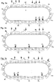
- FIGS. 3a to 3c show schematically a transport route 8 with ten groups or periods P1 - P10 each consisting of three stop positions for workpiece carrier sections, the stop positions in each stop position period being numbered with the stop position numbers 1-3, so that the stop position numbers 1, 2, 3 occur ten times.
- the stop positions are distributed equidistantly along the first transport path 8, just as workpiece carrier sections (not shown) are accordingly evenly distributed along the first transport path 8.
- the stop position numbers and the workpiece carrier section numbers are always mapped 1: 1 to one another in this model, so that at the stop positions with the stop position number 1 only workpiece carrier sections with the workpiece carrier section number 1 are held, at the stop positions with the stop position number 2 only workpiece carrier sections with the workpiece carrier section number 2 are held and only workpiece carrier sections with workpiece carrier section number 3 stop at the stop positions with stop position number 3. (This can be generalized for any positive whole number n in the case of n existing assembly devices with a corresponding adaptation of the step size and position period or workpiece carrier section group).
- the 3 mounting devices in the Figures 3a to 3c are distributed in their assignment to stop positions of the workpiece carrier sections along the first transport path via stop positions with the numbers 1 to 3, with a respective assembly device for each stop position number. If a mounting device is assigned to a stop position with a specific stop position number in a stop position period, no mounting device is assigned to the same stop position number of another stop position period. This results in various options for positioning the three mounting devices, three of which are in the Figures 3a to 3c are indicated by the double arrows 18, 20, 21.
- the assembly devices represented by the double arrows 18, 20, 21 are distributed over three successive stop position periods P1, P2, P3, whereby in this case, too, when a assembly device is assigned to a stop position number, no further assignment of an assembly device to the same stop position number in a different stop position period P. occurs. Since in this example the Figure 3b If the assembly device represented by the double arrow 18 is already assigned to the stop position number 1 in the stop position period P1, it does not happen that the stop position number 1 is assigned to a further assembly device of the type considered here in any other stop position period P.
- FIG. 3c Another example of the distribution of the mounting devices is shown, in this example the stop position number 1 in the stop position period P1 is assigned a mounting device (represented there by the double arrow 18), whereas the stop position numbers 2 and 3 in the stop position period P3 each have a mounting device (there by the double arrows 20 and 21 respectively) is assigned.
- transfer devices for supplying first component components to workpiece carrier sections can be distributed at relevant stop positions, as shown in FIG Figures 3a to 3c is also indicated on the basis of three examples, the transfer devices being represented by the arrows U1, U2, U3 pointing from the outside to the stop positions.
- the number of transfer devices corresponds to the number n of assembly devices.
- discharge devices for removing and diverting finished components or the like from relevant workpiece carrier sections can also be distributed at relevant stop positions, as shown in FIGS Figures 3a to 3c is also indicated on the basis of three examples, the dispensing devices being represented by arrows A1, A2, A3 pointing outward from the stop positions.
- the number of dispensing devices corresponds to the number n of assembly devices.
- the exemplary embodiments of the invention explained above with reference to the figures are those in which the first transport device was operated in a clocked, intermittent, that is, discontinuous, mode. As explained above, correspondingly constructed devices according to the invention can also be set up for continuous operation of the first transport device.
Landscapes
- Engineering & Computer Science (AREA)
- Mechanical Engineering (AREA)
- Manufacturing & Machinery (AREA)
- Automatic Assembly (AREA)
Claims (13)
- Dispositif pour la fabrication de modules (40) à partir d'au moins deux composants de module (12, 22) respectifs en série, comprenant- un nombre prédéterminé n>1 de dispositifs de montage (18, 20) pour assembler des premiers composants de module (12) et des deuxièmes composants de module (22) en modules (40),- un premier dispositif de transport (2), adapté pour transporter des premiers composants de module (12) vers les dispositifs de montage (18, 20), le long d'une première section de transport (8) adaptée comme trajet sans fin fermé, de telle sorte qu'à tous les dispositifs de montage (18, 20), à des moments de mise à disposition successifs déterminés du premier dispositif de transport (2), au moins un premier composant de module (12) soit disponible pour une prise en contrôle essentiellement simultanée ou/et un traitement par les dispositifs de montage (18, 20),- un deuxième dispositif de transport (30 - 32), adapté pour transporter des deuxièmes composants de module (22) vers les dispositifs de montage (18, 20), de telle sorte qu'à des moments de mise à disposition du premier dispositif de transport (2) un nombre respectif de deuxièmes composants de module (22) soit disponible aux dispositifs de montage (18, 20) correspondant au besoin de deuxièmes composants de module (22) pour l'assemblage avec les premiers composants de module (12) aux dispositifs de montage (18, 20),
dans lequel le premier dispositif de transport (2) comprend le long du premier trajet de transport (8) des sections porte-pièces (6) se succédant de manière au moins approximativement équidistante et est adapté pour les déplacer en circulation le long du premier trajet de transport (8), dans lequel les sections porte-pièces (6) sont adaptées individuellement pour transporter un premier composant de module (12) ou, au choix, un groupe respectif de premiers composant de module (12) pour le transport et pour les déplacer le long du premier trajet de transport (8) en fonction du mouvement de transport du premier dispositif de transport (2), dans lequel, au moins dans une certaine section du premier trajet de transport (8) les distances entre les positions des dispositifs de montage (18, 20) le long du premier trajet de transport (8) correspondent à la distance (x) entre des points similaires, de préférence des centres de deux sections porte-pièces (6) se succédant le long du premier trajet de transport (8) ou à un multiple entier de celle-ci,
caractérisé en ce que le premier dispositif de transport (2) est adapté pour faire avancer en continu les sections porte-pièces (6) avec une vitesse d'avance (V) le long du premier trajet de transport (8), la vitesse d'avance (V) et les distances (D) entre les positions des dispositifs de montage (18, 20) le long du premier trajet de transport (8) étant adaptées les unes aux autres de telle sorte que, pendant le fonctionnement du premier dispositif de transport (2) - au moins après une phase de démarrage - une section porte-pièce (6) respective est mise à disposition à tous les dispositifs de montage (18, 20) aux moments de mise à disposition du premier dispositif de transport (2) de telle sorte que, lors d'une circulation du premier dispositif de transport (2), chacune des sections porte-pièce (6) est mise à disposition en série à un moment de mise à disposition respectif à un dispositif de montage (20, 20) respectif concerné, aucune section porte-pièce (6) n'étant prévue à plus d'un dispositif de montage (18, 20). - Dispositif pour la fabrication de modules (40) à partir d'au moins deux composants de module (12, 22) respectifs, en série, comprenant- un nombre déterminé n>1 de dispositifs de montage (18, 20) pour assembler des premiers composants de module (12) et des deuxièmes composants de module (22) en modules (40),- un premier dispositif de transport (2) adapté pour transporter des premiers composants de module (12) vers les dispositifs de montage (18, 20) le long d'un premier trajet de transport (8) adapté comme trajet sans fin fermé, de telle sorte qu'un premier composant de module (12) respectif est prévu à tous les dispositifs de montage (18, 20) à des moments de mise à disposition successifs déterminés du premier dispositif de transport (2) pour un transfert et/ou un traitement essentiellement simultané par les dispositifs de montage (18, 20),- un deuxième dispositif de transport (30 - 32) qui est adapté pour transporter des deuxièmes composants de module (22) vers les dispositifs de montage (18, 20) de telle sorte qu'un certain nombre de deuxièmes composants de module (22) respectif est prévu aux dispositifs de montage (18, 20) aux moments de mise à disposition du premier dispositif de transport (2), correspondant au besoin respectif de deuxièmes composants de module (22) pour l'assemblage avec les premiers composants de module (12) aux dispositifs de montage (18, 20),
dans lequel le premier dispositif de transport (2) comprend le long du premier trajet de transport (8) des sections porte-pièces (6) se succédant de manière au moins approximativement équidistante et est adapté pour les déplacer en circulation le long du premier trajet de transport (8), dans lequel les sections porte-pièces (6) sont adaptées individuellement pour transporter un premier composant de module (12) ou, au choix, un groupe respectif de premiers composant de module (12) pour le transport et pour les déplacer le long du premier trajet de transport (8) en fonction du mouvement de transport du premier dispositif de transport (2), dans lequel, au moins dans une certaine section du premier trajet de transport (8) les distances entre les positions des dispositifs de montage (18, 20) le long du premier trajet de transport (8) correspondent à la distance (x) entre des points similaires, de préférence aux centres de deux sections porte-pièces (6) se succédant le long du premier trajet de transport (8) ou à un multiple entier de celle-ci,
dans lequel le premier dispositif de transport (2) est adapté pour avancer les sections porte-pièces (6) de manière intermittente avec une taille de pas donnée (S) le long du premier trajet de transport (8),
caractérisé en ce que les distances (D) entre les positions des dispositifs de montage (18, 20) le long du premier trajet de transport (8) sont alignés de telle sorte que pendant le fonctionnement du premier dispositif de transport (2) - au moins après une phase de démarrage - une section porte-pièce (6) respective est mise à disposition à tous les dispositifs de montage (18, 20) à des moments d'arrêt du mouvement de transport intermittent correspondant aux moments de mise à disposition du premier dispositif de transport (2) de telle sorte que, lors d'une circulation du premier dispositif de transport (2), chacune des sections porte-pièce (6) est mise à disposition en série à un moment d'arrêt du mouvement de transport intermittent à un dispositif de montage (18, 20) respectif concerné, aucune section porte-pièce (6) n'étant prévue à plus d'un dispositif de montage (18, 20). - Dispositif pour la fabrication de modules à partir d'au moins deux composants de module respectifs, en série selon la revendication 1 ou 2, caractérisé en ce que le premier dispositif de transport (2) est adapté pour transporter des premiers composants de module (12) par groupes vers les dispositifs de montage (18, 20) de telle sorte qu'aux moments de mise à disposition du premier dispositif de transport (2), un groupe respectif de premiers composants de module (12) est prévu à chacun des dispositifs de montage (18, 20) pour un traitement sensiblement simultané par les dispositifs de montage (18, 20).
- Dispositif pour la fabrication de modules à partir d'au moins deux composants de module respectifs, en série selon la revendication 1 ou la revendication 3 en combinaison avec la revendication 1, caractérisé en ce que les moments de mise à disposition du premier dispositif de transport (2) se succèdent périodiquement avec un intervalle de temps Δt, dans lequel le premier dispositif de transport (2) est adapté pour faire avancer en continu les sections porte-pièces (6) le long du premier trajet de transport (2) à une vitesse d'avance V, de préférence constante, qui correspond sensiblement à n fois la distance x entre des points similaires, de préférence les centres de deux sections porte-pièces (6) successives le long du premier trajet de transport (8), divisée par l'intervalle de temps Δt entre deux moments de mise à disposition successifs, c'est-à-dire

- Dispositif pour la fabrication de modules à partir d'au moins deux composants de module respectifs, en série selon la revendication 2 ou la revendication 3 en combinaison avec la revendication 2, caractérisé en ce que la taille de pas S du mouvement de transport intermittent du premier dispositif de transport (2) correspond sensiblement à n fois la distance x entre des points similaires, de préférence les centres de deux sections porte-pièce (6) successives le long du premier trajet de transport (8), de telle sorte que pendant chaque pas, des groupes de n sections porte-pièces (6) successives sont avancés d'une distance S = n x dans la direction de transport, où n est le nombre de dispositifs de montage.
- Dispositif pour la fabrication de modules à partir d'au moins deux composants de module respectifs, en série selon l'une des revendications précédentes, caractérisé en ce que deux dispositifs de montage (18, 20) sont prévus de telle sorte que la distance (D) entre les positions des deux dispositifs de montage (18, 20) le long du premier trajet de transport (8) correspond à la distance x entre des points similaires, de préférence les centres de deux sections porte-pièces (6) successives le long du premier trajet de transport (8) ou à un multiple impair de celle-ci.
- Dispositif pour la fabrication de modules à partir d'au moins deux composants de module respectifs, en série selon l'une des revendications précédentes, caractérisé en ce que le premier trajet de transport (8) présente au moins une section linéaire (16) et que les dispositifs de montage (18, 20) sont positionnés sur ladite au moins une section linéaire (16) du premier trajet de transport (8).
- Dispositif pour la fabrication de modules à partir d'au moins deux composants de module respectifs, en série selon l'une des revendications précédentes, caractérisé en ce que le deuxième dispositif de transport (30 - 32) est adapté pour transporter les deuxièmes composants de module (22) sur une bande de support (24 ; 24a, 24b) associée à ceux-ci, de telle sorte qu'aux moments de mise à disposition du premier dispositif de transport (2) aux dispositifs de montage (18, 20), il y a toujours un nombre respectif de deuxièmes composants de module (22) disponibles, correspondant au besoin en deuxièmes composants (22) pour l'assemblage avec les premiers composants de module (12) sur les dispositifs de montage (18, 20) dans chaque cas.
- Dispositif pour la fabrication de modules à partir d'au moins deux composants de module respectifs, en série selon la revendication 8, caractérisé en ce que la bande de support (24 ; 24a, 24b) et les deuxièmes composants de module (22) qui y sont disposés sont une bande découpée dans laquelle la bande de support (24 ; 24a, 24b) et les deuxièmes composants de module (22) sont assemblés de manière à présenter une cohésion matérielle.
- Dispositif pour la fabrication de modules à partir d'au moins deux composants de module respectifs, en série selon l'une des revendications 8 à 9, caractérisé en ce qu'aux différents dispositifs de montage (18, 30, 20) est associé respectivement un dispositif pour séparer les seconds composants de composants (22) prévus de leur bande de support (24 ; 24a, 24b).
- Dispositif pour la fabrication de modules à partir d'au moins deux composants de module respectifs, en série selon l'une des revendications 8 à 10, caractérisé en ce que la bande de support (24a, 24b), de préférence dans une version sous forme de bande découpée, présente une division longitudinale de telle sorte qu'elle présente deux sections de bande de couture de bord séparées s'étendant dans le sens longitudinal de la bande, dont la distance est sensiblement constante transversalement à la direction longitudinale de la bande et dont chacune forme une partie de bord de bande de support (24a, 24b) à partir de laquelle des deuxièmes composants de module (22) respectifs font successivement saillie dans la direction longitudinale de la bande avec des espaces libres entre elles transversalement à la direction longitudinale de la bande, de telle sorte que les deuxièmes composants de module (22) d'une bande de support (24a) font saillie dans les espaces libres des composants de module de l'autre bande de support (24b).
- Dispositif pour la fabrication de modules à partir d'au moins deux composants de module respectifs, en série selon l'une des revendications précédentes, dans lequel au moins un dispositif de transfert (14, 15 ; 14a, 15a, 14b, 15b) est associé au premier dispositif de transport (2), adapté pour amener des premiers composants de module (12) aux sections porte-pièces (6) du premier dispositif de transport (2), de telle sorte que chaque section porte-pièces (6) reçoit un nombre respectif de premiers composants de module (12) à transporter au moyen du premier dispositif de transport (2) vers les dispositifs de montage (18, 20).
- Dispositif pour la fabrication de modules à partir d'au moins deux composants de module respectifs, en série selon l'une des revendications précédentes, dans lequel au moins un dispositif de déchargement (43, 44) est associé au premier dispositif de transport (2) adapté pour décharger des composants finis (40) des sections de porte-pièces (6) du premier dispositif de transport (2).
Priority Applications (1)
| Application Number | Priority Date | Filing Date | Title |
|---|---|---|---|
| PL17176006T PL3258552T3 (pl) | 2016-06-17 | 2017-06-14 | Urządzenie do wytwarzania elementów konstrukcyjnych z co najmniej dwóch komponentów elementu konstrukcyjnego w produkcji seryjnej |
Applications Claiming Priority (1)
| Application Number | Priority Date | Filing Date | Title |
|---|---|---|---|
| DE102016210877.8A DE102016210877A1 (de) | 2016-06-17 | 2016-06-17 | Vorrichtung zur Herstellung eines Bauteils aus wenigstens zwei Bauteilkomponenten in Serienfertigung |
Publications (2)
| Publication Number | Publication Date |
|---|---|
| EP3258552A1 EP3258552A1 (fr) | 2017-12-20 |
| EP3258552B1 true EP3258552B1 (fr) | 2020-08-12 |
Family
ID=59227463
Family Applications (1)
| Application Number | Title | Priority Date | Filing Date |
|---|---|---|---|
| EP17176006.9A Not-in-force EP3258552B1 (fr) | 2016-06-17 | 2017-06-14 | Dispositif de fabrication d'un composant à partir d'au moins deux composants fabriqués en série |
Country Status (4)
| Country | Link |
|---|---|
| EP (1) | EP3258552B1 (fr) |
| DE (1) | DE102016210877A1 (fr) |
| ES (1) | ES2818196T3 (fr) |
| PL (1) | PL3258552T3 (fr) |
Families Citing this family (1)
| Publication number | Priority date | Publication date | Assignee | Title |
|---|---|---|---|---|
| CN115476147A (zh) * | 2022-07-04 | 2022-12-16 | 深圳市海目星激光智能装备股份有限公司 | 压装机构、压装方法及压装生产线 |
Family Cites Families (4)
| Publication number | Priority date | Publication date | Assignee | Title |
|---|---|---|---|---|
| US3561114A (en) * | 1968-09-18 | 1971-02-09 | Berg Electronics Inc | Bobbin lugger and method |
| DE2801115A1 (de) * | 1978-01-12 | 1979-07-19 | Grote & Hartmann | Gehaeusebestueckungsverfahren sowie vorrichtung zu seiner durchfuehrung |
| US4868977A (en) * | 1985-11-27 | 1989-09-26 | Matsushita Electric Industrial Co., Ltd. | Working apparatus |
| US5008999A (en) * | 1990-03-29 | 1991-04-23 | Amp Incorporated | Method of assembling components to electrical terminals |
-
2016
- 2016-06-17 DE DE102016210877.8A patent/DE102016210877A1/de not_active Withdrawn
-
2017
- 2017-06-14 PL PL17176006T patent/PL3258552T3/pl unknown
- 2017-06-14 EP EP17176006.9A patent/EP3258552B1/fr not_active Not-in-force
- 2017-06-14 ES ES17176006T patent/ES2818196T3/es active Active
Non-Patent Citations (1)
| Title |
|---|
| None * |
Also Published As
| Publication number | Publication date |
|---|---|
| EP3258552A1 (fr) | 2017-12-20 |
| DE102016210877A1 (de) | 2017-12-21 |
| ES2818196T3 (es) | 2021-04-09 |
| PL3258552T3 (pl) | 2021-01-11 |
Similar Documents
| Publication | Publication Date | Title |
|---|---|---|
| AT390423B (de) | Verfahren und einrichtung zum herstellen von werkstuecken | |
| DE69620436T2 (de) | Herstellung von rasierklingen | |
| EP2679524B2 (fr) | Dispositif et procédé pour répartir un flux de produits | |
| EP1520682B1 (fr) | Appareil de thermoformage | |
| EP2502509B1 (fr) | Automate d'épluchage pour produit à éplucher étendu et procédé d'épluchage | |
| DE102007059303A1 (de) | Verarbeitungsanlage | |
| DE19826627C2 (de) | Anlage für die Durchführung einer Folge aus mehreren Montage- und/oder Bearbeitungsvorgängen an Werkstücken, insbesondere Kleinteilen | |
| DE102009026043A1 (de) | Vorrichtung und Verfahren zum Beschicken einer Weiterverarbeitungseinheit mit Artikeln | |
| EP3258552B1 (fr) | Dispositif de fabrication d'un composant à partir d'au moins deux composants fabriqués en série | |
| DE102021005580B4 (de) | Montagevorrichtung und Verfahren zur gleichzeitigen Montage mindestens dreier Bauteile in dieser Montagevorrichtung | |
| DE3420424C2 (fr) | ||
| EP0358065A2 (fr) | Agencement pour avancer le traitement des tabloids | |
| DE19629800C1 (de) | Verfahren und Vorrichtung zum Zuführen von mehreren Teilen bei der Montage zu einem neuen Teil | |
| DE10057000A1 (de) | Vorrichtung zum Herstellen von "Zwei- oder Multimetallmünzen" aus unterschiedlichen Metallen | |
| DE3924156C2 (de) | Vorrichtung zum Ver- bzw. Bearbeiten von elektrischen Bauelementen | |
| DE3201401C2 (fr) | ||
| DE69006993T2 (de) | Fertigungseinrichtung mit einer Vorrichtung zum schnellen Zuführen und Positionieren im doppelten Pilgerschritt und Fertigungssystem zum Verwenden dieser Einrichtung. | |
| DE102023003654B3 (de) | Vorrichtung und Verfahren zur Montage eines Spritzgussteils an einem Bauteil sowie Trägerstreifen hierzu | |
| DE102023127114B4 (de) | Blechbearbeitungsanordnung und Verfahren zum Betreiben einer Blechbearbeitungsanordnung | |
| DE102006041494B3 (de) | Verfahren und Vorrichtung zur Herstellung eines Gleitlagerelementes | |
| DE2746048C3 (de) | Vorrichtung zum Zuführen von Platinen in den Werkzeugraum einer Presse und zum Abführen ausgestanzter Werkstücke sowie der Stanzgitter aus dem Werkzeugraum | |
| DE3249850C2 (fr) | ||
| DE1926065A1 (de) | Automatische Einrichtung zur Herstellung von Blechpaketen | |
| EP1564143A1 (fr) | Dispositif de mise sur des objets de parties de feuilles d'une bande | |
| DE19601207A1 (de) | Rangier- und/oder Positionierstufe für eine Stückguttransportanlage |
Legal Events
| Date | Code | Title | Description |
|---|---|---|---|
| PUAI | Public reference made under article 153(3) epc to a published international application that has entered the european phase |
Free format text: ORIGINAL CODE: 0009012 |
|
| STAA | Information on the status of an ep patent application or granted ep patent |
Free format text: STATUS: THE APPLICATION HAS BEEN PUBLISHED |
|
| AK | Designated contracting states |
Kind code of ref document: A1 Designated state(s): AL AT BE BG CH CY CZ DE DK EE ES FI FR GB GR HR HU IE IS IT LI LT LU LV MC MK MT NL NO PL PT RO RS SE SI SK SM TR |
|
| AX | Request for extension of the european patent |
Extension state: BA ME |
|
| STAA | Information on the status of an ep patent application or granted ep patent |
Free format text: STATUS: REQUEST FOR EXAMINATION WAS MADE |
|
| 17P | Request for examination filed |
Effective date: 20180619 |
|
| RBV | Designated contracting states (corrected) |
Designated state(s): AL AT BE BG CH CY CZ DE DK EE ES FI FR GB GR HR HU IE IS IT LI LT LU LV MC MK MT NL NO PL PT RO RS SE SI SK SM TR |
|
| STAA | Information on the status of an ep patent application or granted ep patent |
Free format text: STATUS: EXAMINATION IS IN PROGRESS |
|
| 17Q | First examination report despatched |
Effective date: 20190403 |
|
| GRAP | Despatch of communication of intention to grant a patent |
Free format text: ORIGINAL CODE: EPIDOSNIGR1 |
|
| STAA | Information on the status of an ep patent application or granted ep patent |
Free format text: STATUS: GRANT OF PATENT IS INTENDED |
|
| RIC1 | Information provided on ipc code assigned before grant |
Ipc: H01H 11/00 20060101ALI20191217BHEP Ipc: H01R 13/24 20060101ALI20191217BHEP Ipc: H01R 43/20 20060101AFI20191217BHEP Ipc: B23P 21/00 20060101ALI20191217BHEP Ipc: H05K 13/04 20060101ALI20191217BHEP Ipc: B23Q 7/03 20060101ALI20191217BHEP Ipc: H01R 43/16 20060101ALN20191217BHEP |
|
| INTG | Intention to grant announced |
Effective date: 20200122 |
|
| GRAJ | Information related to disapproval of communication of intention to grant by the applicant or resumption of examination proceedings by the epo deleted |
Free format text: ORIGINAL CODE: EPIDOSDIGR1 |
|
| STAA | Information on the status of an ep patent application or granted ep patent |
Free format text: STATUS: EXAMINATION IS IN PROGRESS |
|
| GRAP | Despatch of communication of intention to grant a patent |
Free format text: ORIGINAL CODE: EPIDOSNIGR1 |
|
| STAA | Information on the status of an ep patent application or granted ep patent |
Free format text: STATUS: GRANT OF PATENT IS INTENDED |
|
| INTC | Intention to grant announced (deleted) | ||
| RIC1 | Information provided on ipc code assigned before grant |
Ipc: B23Q 7/03 20060101ALI20200324BHEP Ipc: H05K 13/04 20060101ALI20200324BHEP Ipc: B23P 21/00 20060101ALI20200324BHEP Ipc: H01R 43/16 20060101ALN20200324BHEP Ipc: H01R 43/20 20060101AFI20200324BHEP Ipc: H01H 11/00 20060101ALI20200324BHEP Ipc: H01R 13/24 20060101ALI20200324BHEP |
|
| INTG | Intention to grant announced |
Effective date: 20200407 |
|
| GRAS | Grant fee paid |
Free format text: ORIGINAL CODE: EPIDOSNIGR3 |
|
| GRAA | (expected) grant |
Free format text: ORIGINAL CODE: 0009210 |
|
| STAA | Information on the status of an ep patent application or granted ep patent |
Free format text: STATUS: THE PATENT HAS BEEN GRANTED |
|
| AK | Designated contracting states |
Kind code of ref document: B1 Designated state(s): AL AT BE BG CH CY CZ DE DK EE ES FI FR GB GR HR HU IE IS IT LI LT LU LV MC MK MT NL NO PL PT RO RS SE SI SK SM TR |
|
| REG | Reference to a national code |
Ref country code: CH Ref legal event code: EP |
|
| REG | Reference to a national code |
Ref country code: IE Ref legal event code: FG4D Free format text: LANGUAGE OF EP DOCUMENT: GERMAN |
|
| REG | Reference to a national code |
Ref country code: DE Ref legal event code: R096 Ref document number: 502017006683 Country of ref document: DE |
|
| REG | Reference to a national code |
Ref country code: AT Ref legal event code: REF Ref document number: 1302472 Country of ref document: AT Kind code of ref document: T Effective date: 20200915 |
|
| REG | Reference to a national code |
Ref country code: LT Ref legal event code: MG4D |
|
| REG | Reference to a national code |
Ref country code: NL Ref legal event code: MP Effective date: 20200812 |
|
| PG25 | Lapsed in a contracting state [announced via postgrant information from national office to epo] |
Ref country code: LT Free format text: LAPSE BECAUSE OF FAILURE TO SUBMIT A TRANSLATION OF THE DESCRIPTION OR TO PAY THE FEE WITHIN THE PRESCRIBED TIME-LIMIT Effective date: 20200812 Ref country code: FI Free format text: LAPSE BECAUSE OF FAILURE TO SUBMIT A TRANSLATION OF THE DESCRIPTION OR TO PAY THE FEE WITHIN THE PRESCRIBED TIME-LIMIT Effective date: 20200812 Ref country code: SE Free format text: LAPSE BECAUSE OF FAILURE TO SUBMIT A TRANSLATION OF THE DESCRIPTION OR TO PAY THE FEE WITHIN THE PRESCRIBED TIME-LIMIT Effective date: 20200812 Ref country code: HR Free format text: LAPSE BECAUSE OF FAILURE TO SUBMIT A TRANSLATION OF THE DESCRIPTION OR TO PAY THE FEE WITHIN THE PRESCRIBED TIME-LIMIT Effective date: 20200812 Ref country code: GR Free format text: LAPSE BECAUSE OF FAILURE TO SUBMIT A TRANSLATION OF THE DESCRIPTION OR TO PAY THE FEE WITHIN THE PRESCRIBED TIME-LIMIT Effective date: 20201113 Ref country code: BG Free format text: LAPSE BECAUSE OF FAILURE TO SUBMIT A TRANSLATION OF THE DESCRIPTION OR TO PAY THE FEE WITHIN THE PRESCRIBED TIME-LIMIT Effective date: 20201112 Ref country code: NO Free format text: LAPSE BECAUSE OF FAILURE TO SUBMIT A TRANSLATION OF THE DESCRIPTION OR TO PAY THE FEE WITHIN THE PRESCRIBED TIME-LIMIT Effective date: 20201112 |
|
| PG25 | Lapsed in a contracting state [announced via postgrant information from national office to epo] |
Ref country code: RS Free format text: LAPSE BECAUSE OF FAILURE TO SUBMIT A TRANSLATION OF THE DESCRIPTION OR TO PAY THE FEE WITHIN THE PRESCRIBED TIME-LIMIT Effective date: 20200812 Ref country code: NL Free format text: LAPSE BECAUSE OF FAILURE TO SUBMIT A TRANSLATION OF THE DESCRIPTION OR TO PAY THE FEE WITHIN THE PRESCRIBED TIME-LIMIT Effective date: 20200812 Ref country code: LV Free format text: LAPSE BECAUSE OF FAILURE TO SUBMIT A TRANSLATION OF THE DESCRIPTION OR TO PAY THE FEE WITHIN THE PRESCRIBED TIME-LIMIT Effective date: 20200812 Ref country code: IS Free format text: LAPSE BECAUSE OF FAILURE TO SUBMIT A TRANSLATION OF THE DESCRIPTION OR TO PAY THE FEE WITHIN THE PRESCRIBED TIME-LIMIT Effective date: 20201212 |
|
| REG | Reference to a national code |
Ref country code: ES Ref legal event code: FG2A Ref document number: 2818196 Country of ref document: ES Kind code of ref document: T3 Effective date: 20210409 |
|
| PG25 | Lapsed in a contracting state [announced via postgrant information from national office to epo] |
Ref country code: DK Free format text: LAPSE BECAUSE OF FAILURE TO SUBMIT A TRANSLATION OF THE DESCRIPTION OR TO PAY THE FEE WITHIN THE PRESCRIBED TIME-LIMIT Effective date: 20200812 Ref country code: RO Free format text: LAPSE BECAUSE OF FAILURE TO SUBMIT A TRANSLATION OF THE DESCRIPTION OR TO PAY THE FEE WITHIN THE PRESCRIBED TIME-LIMIT Effective date: 20200812 Ref country code: EE Free format text: LAPSE BECAUSE OF FAILURE TO SUBMIT A TRANSLATION OF THE DESCRIPTION OR TO PAY THE FEE WITHIN THE PRESCRIBED TIME-LIMIT Effective date: 20200812 Ref country code: SM Free format text: LAPSE BECAUSE OF FAILURE TO SUBMIT A TRANSLATION OF THE DESCRIPTION OR TO PAY THE FEE WITHIN THE PRESCRIBED TIME-LIMIT Effective date: 20200812 |
|
| REG | Reference to a national code |
Ref country code: DE Ref legal event code: R097 Ref document number: 502017006683 Country of ref document: DE |
|
| PG25 | Lapsed in a contracting state [announced via postgrant information from national office to epo] |
Ref country code: AL Free format text: LAPSE BECAUSE OF FAILURE TO SUBMIT A TRANSLATION OF THE DESCRIPTION OR TO PAY THE FEE WITHIN THE PRESCRIBED TIME-LIMIT Effective date: 20200812 |
|
| PLBE | No opposition filed within time limit |
Free format text: ORIGINAL CODE: 0009261 |
|
| STAA | Information on the status of an ep patent application or granted ep patent |
Free format text: STATUS: NO OPPOSITION FILED WITHIN TIME LIMIT |
|
| PG25 | Lapsed in a contracting state [announced via postgrant information from national office to epo] |
Ref country code: SK Free format text: LAPSE BECAUSE OF FAILURE TO SUBMIT A TRANSLATION OF THE DESCRIPTION OR TO PAY THE FEE WITHIN THE PRESCRIBED TIME-LIMIT Effective date: 20200812 |
|
| 26N | No opposition filed |
Effective date: 20210514 |
|
| PG25 | Lapsed in a contracting state [announced via postgrant information from national office to epo] |
Ref country code: SI Free format text: LAPSE BECAUSE OF FAILURE TO SUBMIT A TRANSLATION OF THE DESCRIPTION OR TO PAY THE FEE WITHIN THE PRESCRIBED TIME-LIMIT Effective date: 20200812 |
|
| PG25 | Lapsed in a contracting state [announced via postgrant information from national office to epo] |
Ref country code: MC Free format text: LAPSE BECAUSE OF FAILURE TO SUBMIT A TRANSLATION OF THE DESCRIPTION OR TO PAY THE FEE WITHIN THE PRESCRIBED TIME-LIMIT Effective date: 20200812 |
|
| REG | Reference to a national code |
Ref country code: CH Ref legal event code: PL |
|
| REG | Reference to a national code |
Ref country code: BE Ref legal event code: MM Effective date: 20210630 |
|
| PG25 | Lapsed in a contracting state [announced via postgrant information from national office to epo] |
Ref country code: LU Free format text: LAPSE BECAUSE OF NON-PAYMENT OF DUE FEES Effective date: 20210614 |
|
| PG25 | Lapsed in a contracting state [announced via postgrant information from national office to epo] |
Ref country code: LI Free format text: LAPSE BECAUSE OF NON-PAYMENT OF DUE FEES Effective date: 20210630 Ref country code: IE Free format text: LAPSE BECAUSE OF NON-PAYMENT OF DUE FEES Effective date: 20210614 Ref country code: CH Free format text: LAPSE BECAUSE OF NON-PAYMENT OF DUE FEES Effective date: 20210630 |
|
| PG25 | Lapsed in a contracting state [announced via postgrant information from national office to epo] |
Ref country code: BE Free format text: LAPSE BECAUSE OF NON-PAYMENT OF DUE FEES Effective date: 20210630 |
|
| PG25 | Lapsed in a contracting state [announced via postgrant information from national office to epo] |
Ref country code: PT Free format text: LAPSE BECAUSE OF FAILURE TO SUBMIT A TRANSLATION OF THE DESCRIPTION OR TO PAY THE FEE WITHIN THE PRESCRIBED TIME-LIMIT Effective date: 20201214 |
|
| PG25 | Lapsed in a contracting state [announced via postgrant information from national office to epo] |
Ref country code: HU Free format text: LAPSE BECAUSE OF FAILURE TO SUBMIT A TRANSLATION OF THE DESCRIPTION OR TO PAY THE FEE WITHIN THE PRESCRIBED TIME-LIMIT; INVALID AB INITIO Effective date: 20170614 |
|
| P01 | Opt-out of the competence of the unified patent court (upc) registered |
Effective date: 20230512 |
|
| PG25 | Lapsed in a contracting state [announced via postgrant information from national office to epo] |
Ref country code: CY Free format text: LAPSE BECAUSE OF FAILURE TO SUBMIT A TRANSLATION OF THE DESCRIPTION OR TO PAY THE FEE WITHIN THE PRESCRIBED TIME-LIMIT Effective date: 20200812 |
|
| PGFP | Annual fee paid to national office [announced via postgrant information from national office to epo] |
Ref country code: FR Payment date: 20230628 Year of fee payment: 7 Ref country code: DE Payment date: 20230531 Year of fee payment: 7 Ref country code: CZ Payment date: 20230606 Year of fee payment: 7 |
|
| REG | Reference to a national code |
Ref country code: AT Ref legal event code: MM01 Ref document number: 1302472 Country of ref document: AT Kind code of ref document: T Effective date: 20220614 |
|
| PGFP | Annual fee paid to national office [announced via postgrant information from national office to epo] |
Ref country code: PL Payment date: 20230601 Year of fee payment: 7 |
|
| PG25 | Lapsed in a contracting state [announced via postgrant information from national office to epo] |
Ref country code: AT Free format text: LAPSE BECAUSE OF NON-PAYMENT OF DUE FEES Effective date: 20220614 |
|
| PGFP | Annual fee paid to national office [announced via postgrant information from national office to epo] |
Ref country code: IT Payment date: 20230623 Year of fee payment: 7 Ref country code: GB Payment date: 20230622 Year of fee payment: 7 Ref country code: ES Payment date: 20230830 Year of fee payment: 7 |
|
| PG25 | Lapsed in a contracting state [announced via postgrant information from national office to epo] |
Ref country code: MK Free format text: LAPSE BECAUSE OF FAILURE TO SUBMIT A TRANSLATION OF THE DESCRIPTION OR TO PAY THE FEE WITHIN THE PRESCRIBED TIME-LIMIT Effective date: 20200812 |
|
| PG25 | Lapsed in a contracting state [announced via postgrant information from national office to epo] |
Ref country code: MT Free format text: LAPSE BECAUSE OF FAILURE TO SUBMIT A TRANSLATION OF THE DESCRIPTION OR TO PAY THE FEE WITHIN THE PRESCRIBED TIME-LIMIT Effective date: 20200812 |
|
| REG | Reference to a national code |
Ref country code: DE Ref legal event code: R119 Ref document number: 502017006683 Country of ref document: DE |
|
| PG25 | Lapsed in a contracting state [announced via postgrant information from national office to epo] |
Ref country code: CZ Free format text: LAPSE BECAUSE OF NON-PAYMENT OF DUE FEES Effective date: 20240614 |
|
| PG25 | Lapsed in a contracting state [announced via postgrant information from national office to epo] |
Ref country code: CZ Free format text: LAPSE BECAUSE OF NON-PAYMENT OF DUE FEES Effective date: 20240614 |
|
| GBPC | Gb: european patent ceased through non-payment of renewal fee |
Effective date: 20240614 |
|
| PG25 | Lapsed in a contracting state [announced via postgrant information from national office to epo] |
Ref country code: DE Free format text: LAPSE BECAUSE OF NON-PAYMENT OF DUE FEES Effective date: 20250101 |
|
| PG25 | Lapsed in a contracting state [announced via postgrant information from national office to epo] |
Ref country code: FR Free format text: LAPSE BECAUSE OF NON-PAYMENT OF DUE FEES Effective date: 20240630 |
|
| PG25 | Lapsed in a contracting state [announced via postgrant information from national office to epo] |
Ref country code: IT Free format text: LAPSE BECAUSE OF NON-PAYMENT OF DUE FEES Effective date: 20240614 Ref country code: GB Free format text: LAPSE BECAUSE OF NON-PAYMENT OF DUE FEES Effective date: 20240614 |
|
| REG | Reference to a national code |
Ref country code: ES Ref legal event code: FD2A Effective date: 20250731 |
|
| PG25 | Lapsed in a contracting state [announced via postgrant information from national office to epo] |
Ref country code: ES Free format text: LAPSE BECAUSE OF NON-PAYMENT OF DUE FEES Effective date: 20240615 |
|
| PG25 | Lapsed in a contracting state [announced via postgrant information from national office to epo] |
Ref country code: TR Free format text: LAPSE BECAUSE OF FAILURE TO SUBMIT A TRANSLATION OF THE DESCRIPTION OR TO PAY THE FEE WITHIN THE PRESCRIBED TIME-LIMIT Effective date: 20200812 |
|
| PG25 | Lapsed in a contracting state [announced via postgrant information from national office to epo] |
Ref country code: PL Free format text: LAPSE BECAUSE OF FAILURE TO SUBMIT A TRANSLATION OF THE DESCRIPTION OR TO PAY THE FEE WITHIN THE PRESCRIBED TIME-LIMIT Effective date: 20240614 |
|
| PG25 | Lapsed in a contracting state [announced via postgrant information from national office to epo] |
Ref country code: PL Free format text: LAPSE BECAUSE OF NON-PAYMENT OF DUE FEES Effective date: 20240614 |