EP3258552B1 - Device for producing a component from at least two components in mass production - Google Patents
Device for producing a component from at least two components in mass production Download PDFInfo
- Publication number
- EP3258552B1 EP3258552B1 EP17176006.9A EP17176006A EP3258552B1 EP 3258552 B1 EP3258552 B1 EP 3258552B1 EP 17176006 A EP17176006 A EP 17176006A EP 3258552 B1 EP3258552 B1 EP 3258552B1
- Authority
- EP
- European Patent Office
- Prior art keywords
- transport
- component parts
- workpiece carrier
- assembly devices
- along
- Prior art date
- Legal status (The legal status is an assumption and is not a legal conclusion. Google has not performed a legal analysis and makes no representation as to the accuracy of the status listed.)
- Not-in-force
Links
Images


Classifications
-
- B—PERFORMING OPERATIONS; TRANSPORTING
- B23—MACHINE TOOLS; METAL-WORKING NOT OTHERWISE PROVIDED FOR
- B23P—METAL-WORKING NOT OTHERWISE PROVIDED FOR; COMBINED OPERATIONS; UNIVERSAL MACHINE TOOLS
- B23P21/00—Machines for assembling a multiplicity of different parts to compose units, with or without preceding or subsequent working of such parts, e.g. with program control
- B23P21/004—Machines for assembling a multiplicity of different parts to compose units, with or without preceding or subsequent working of such parts, e.g. with program control the units passing two or more work-stations whilst being composed
-
- H—ELECTRICITY
- H01—ELECTRIC ELEMENTS
- H01R—ELECTRICALLY-CONDUCTIVE CONNECTIONS; STRUCTURAL ASSOCIATIONS OF A PLURALITY OF MUTUALLY-INSULATED ELECTRICAL CONNECTING ELEMENTS; COUPLING DEVICES; CURRENT COLLECTORS
- H01R13/00—Details of coupling devices of the kinds covered by groups H01R12/70 or H01R24/00 - H01R33/00
- H01R13/02—Contact members
- H01R13/22—Contacts for co-operating by abutting
- H01R13/24—Contacts for co-operating by abutting resilient; resiliently-mounted
- H01R13/2407—Contacts for co-operating by abutting resilient; resiliently-mounted characterized by the resilient means
-
- H—ELECTRICITY
- H01—ELECTRIC ELEMENTS
- H01R—ELECTRICALLY-CONDUCTIVE CONNECTIONS; STRUCTURAL ASSOCIATIONS OF A PLURALITY OF MUTUALLY-INSULATED ELECTRICAL CONNECTING ELEMENTS; COUPLING DEVICES; CURRENT COLLECTORS
- H01R43/00—Apparatus or processes specially adapted for manufacturing, assembling, maintaining, or repairing of line connectors or current collectors or for joining electric conductors
- H01R43/20—Apparatus or processes specially adapted for manufacturing, assembling, maintaining, or repairing of line connectors or current collectors or for joining electric conductors for assembling or disassembling contact members with insulating base, case or sleeve
-
- H—ELECTRICITY
- H01—ELECTRIC ELEMENTS
- H01R—ELECTRICALLY-CONDUCTIVE CONNECTIONS; STRUCTURAL ASSOCIATIONS OF A PLURALITY OF MUTUALLY-INSULATED ELECTRICAL CONNECTING ELEMENTS; COUPLING DEVICES; CURRENT COLLECTORS
- H01R43/00—Apparatus or processes specially adapted for manufacturing, assembling, maintaining, or repairing of line connectors or current collectors or for joining electric conductors
- H01R43/16—Apparatus or processes specially adapted for manufacturing, assembling, maintaining, or repairing of line connectors or current collectors or for joining electric conductors for manufacturing contact members, e.g. by punching and by bending
Definitions
- the invention relates to a device with the features of the preamble of claim 1 or the features of the preamble of claim 2 for the production of components from in each case at least two component components in series production.
- Devices for producing a component from component components in series production which include an assembly device for joining first component components and second component components and also have transport devices for feeding the first component component and the second component component to the assembly device.
- the component components are usually supplied in a transport cycle or machine cycle, so that in each case a first component component is moved on a workpiece carrier to the assembly device and the assigned second component component arrives there essentially synchronously, so that in the corresponding machine cycle the second component component with the first component component by means of the Mounting device can be connected.
- this component assembly is transported away from the area of the assembly device by means of the relevant transport device in order to make space for component components that are to be connected to one another.
- components are often multi-component-free components, such as in insulating nests embedded electrical switching contact elements or SMD components (s urface m ounted D evices) for electronic devices or like that.
- the component components can be component components made of different materials and / or different shapes and / or different dimensions.
- An example could be an electrical contact in a plastic holder, wherein the plastic holder could represent a first component component and the electrical contact could represent a second component component in the sense explained above.
- Such multi-component small components are often produced in large numbers in high-speed series production, namely especially when there is a need for large quantities of such components and high cost pressure with regard to their production.
- a generic device with the features of the preamble of claim 1 and the preamble of claim 2 is from the U.S. 3,561,114 A. known.
- the U.S. 3,561,114 A. discloses a device in which the first transport device is set up to move equidistant workpiece carrier sections circumferentially along a closed endless path as the first transport path, clocked and intermittently with a given step size along the first transport path to various work stations arranged along a linear section of the first transport path.
- These workstations include, in particular, two assembly devices on which both sides of a coil are fitted with connections one after the other, so that each coil can be connected to both assembly devices U.S. 3,561,114 A. is processed.
- the object of the present invention is to enable an increase in the productivity of a generic device for producing components from at least two component components, each of which is Assembly devices that manufacture components.
- a device with the features of claim 1 is proposed for continuous transport, and according to the second aspect of the invention, a device with the features of claim 2 for intermittent transport.
- first component components can be assigned a different number of second component elements for common connection.
- One approach of the invention is to position n assembly devices, i.e. at least two assembly devices, along the first transport path, these assembly devices having the task of assembling first component components and second component components, preferably at the same time, to form a respective composite, and the assembly devices being one and the same first transport device are supplied with first component components at the same time as the provision times of the first transport device.
- n assembly devices i.e. at least two assembly devices
- second component components preferably at the same time
- the first transport device can be set up to transport first component components in groups to the assembly devices, so that at the times when the first transport device is made available, a respective group of first component components on each of the assembly devices for essentially simultaneous processing and / or is ready to be taken over by the assembly devices.
- the second transport device provides a respective number of second component components on the assembly devices at the times at which the first transport device is made available ready, which corresponds to the need for second component components for assembling with the first component components on the assembly devices.
- the assembly devices are then to be operated in such a way that they can simultaneously connect component components of the respective group of first component components with correspondingly assigned second component components at or between the provision times of the first transport device. In this way, too, the productivity of the device for producing a component from at least two component components in series production can be increased.
- the first transport path is a closed endless path or loop, the first transport device comprising workpiece carrier sections following at least approximately equidistantly along the first transport path and being configured to move them circumferentially along the first transport path, and wherein the workpiece carrier sections are individually configured to each Pick up the first component component or possibly a respective group of first component components for transport and move it along the first transport path in accordance with the transport movement of the first transport device, the distances between the positions of the assembly devices along the first transport path being the distance at least in a certain section of the first transport path x between similar locations, preferably the centers of two directly successive workpiece carrier sections along the first transport path or correspond to an integer multiple thereof, so that a feed movement of the workpiece carrier sections coordinated with the distance x by the first transport device can be selected in order to supply all n assembly devices with a first component component or, if necessary, a group of first component components at each provision time. In this way, the transport and transport control effort in the supply of the first Component components to the assembly devices are kept low.
- the workpiece carrier sections are preferably holders that are shaped so that they can accommodate first component components or possibly groups of first component components in a desired relative orientation for transport along the first transport path, and which are arranged equidistantly in series on an endless belt which is moved circumferentially by the first transport device along the first transport path in order to always provide a respective workpiece carrier section with a first component component or possibly a group of first component components at the times of provision on the assembly devices at the same time.
- the first transport device can be set up to move the first component components or the workpiece carrier sections continuously, preferably at a constant speed, or discontinuously or intermittently.
- a device according to the invention can also be set up for the optional continuous or discontinuous transport operation of the first transport device.
- the first transport device advances the workpiece carrier sections continuously at a feed speed V along the first transport path, the feed speed V and the distances (D) between the positions of the assembly devices along the first transport path being coordinated with one another that during operation of the first transport device - at least after a start-up phase - a respective workpiece carrier section is available on all assembly devices at the times of provision of the first transport device, so that when the first transport device rotates all workpiece carrier sections serially at the times of provision at one relevant assembly device are provided, wherein no workpiece carrier portion is provided on more than one assembly device.
- the assembly devices are thus placed at selected positions along the first transport path, so that with a complete rotation of the workpiece carrier sections along the first transport path designed as an endless path and with a correspondingly selected feed rate during the transport movement of the first transport device, each workpiece carrier section only once to provide first component components on an assembly device is available at a relevant provision time. At the other times of readiness, the workpiece carrier sections are located outside the assignment area of the assembly devices during the cycle.
- first transport device operated for continuous transport various modes of operation of the assembly devices come into question.
- first component components remain in their respective workpiece carrier sections during the process of joining the first and second component components and that the assembly devices move the workpiece carrier sections over a short distance during their assembly processes of assembling the component components follow the time interval required for the assembly process.
- first component components are briefly and temporarily separated from the workpiece carrier sections for the purpose of joining the first and second component components, all this within a short time interval that is required for the assembly process and in which the workpiece carrier section has been assigned to the relevant assembly device since the last time it was made available.
- transfer means must be set up to include a relevant first To remove component components from their workpiece carrier section at the time of preparation and to return them to the workpiece carrier section after processing by the assembly device after the latter has been moved on by a small section along the first transport path.
- the device can be operated with discontinuous operation of the first transport device.
- This device comprises a certain number n (greater than 1) of assembly devices for assembling first component components and second component components to form components, a first transport device for the clocked, intermittent transport of first component components to the assembly devices along a first transport path designed as a closed endless path, a second transport device for transport second component components to the assembly devices, wherein the first transport device is set up to transport at least one respective first component component to each assembly device in the transport cycle, so that at least one first component component on each assembly device for essentially simultaneous processing during stop times of the intermittent transport movement of the first transport device is available by the assembly devices, wherein the second transport device is set up at the stop times to provide the intermittent transport movement of the first transport device with a respective number of second component components on the assembly devices, which corresponds to the need for second component components for joining with the first component components on the assembly devices.
- the first transport device of this device is set up to move the workpiece carrier sections clocked intermittently with a step size S along the first transport path, the distances (D) between the positions of the assembly devices along the first transport path being coordinated with one another so that During operation of the first transport device - at least after a start-up phase - a respective workpiece carrier section is available at all assembly devices in the stop times of the intermittent transport movement corresponding to the provision times of the first transport device, so that when the first transport device rotates, all workpiece carrier sections serially in the stop times of the intermittent Transport movement are provided on a relevant assembly device, wherein no workpiece carrier portion is provided on more than one assembly device.
- the stop positions along the first transport path can also be numbered periodically, the number of periods corresponding to the number of groups of workpiece carrier sections. Workpiece carrier sections with a certain number only come to a stop at the stop positions with the same number along the first transport path. This applies to all workpiece carrier sections.
- the n assembly devices are distributed in their assignment to stop positions of the workpiece carrier sections along the first transport path via stop positions with the numbers 1 to n, with one assembly device for each stop position number. If a mounting device is assigned to a stop position with a specific stop position number in a period, no mounting device is assigned to the same stop position number in another period.
- the total number of stop positions along the first Transport distance should be divisible by n without a remainder.
- the first transport path has at least one linear section, the assembly devices preferably being positioned on the linear section of the first transport path in association with relevant stop positions of the workpiece carrier sections.
- the first transport path is formed as an oval in plan projection from two semicircular arcs connected to one another by linear sections.
- the linear sections can then be used very well for a space-optimized positioning of the assembly devices on the one hand and of transfer devices for transferring first component components to workpiece carrier sections of the first transport device on the other hand, as well as for the favorable positioning of discharge devices for discharging components from the workpiece carrier sections and for discharging the components from the first Transport facility can be used.
- the second component components are tiny and / or filigree stamped parts.
- These holding strips and the second component components arranged thereon are preferably a punched strip in which the holding strip and the second component components are cohesively connected.
- the holding strip is remnants of a raw material strip that are cohesively connected to the second component components and that has been subjected to a punching process by means of a punching press in order to form the second component components.
- a punch press can be connected directly or indirectly upstream of the device for producing a component from at least two component components in series production, so that the punch strip leaving the punch press is fed directly to the device according to the invention.
- a forming device can also be interposed between such a punch press and the device according to the invention, for example in order to subject the second component components to a bending process; or a welding station to weld on a contact.
- Such devices can optionally also be integrated into the device according to the invention.
- the second transport device is set up to intermittently move the retaining strip with the second component components arranged thereon, the step cycle of the second transport device and the step cycle of the first transport device being coordinated, in particular synchronized, with one another.
- the subsequent density of the second component components on the holding strip is preferably selected so that after each step the respective required amount of second component components for further processing on the assembly devices is pending.
- the assembly devices are each assigned a device for separating the provided second component components from their holding strips. The separated second component components can then be fed to the workpiece carrier sections of the first transport device by means of transfer devices or automatic placement machines of the assembly devices in order to be combined there with the provided first component components.
- the holding strip has a longitudinal division in such a way that it has two separate edge strip sections running in the longitudinal direction of the strip, the distance between them being transverse to the longitudinal direction of the strip Is essentially constant and each of which forms a retaining strip edge section from which respective second component components protrude in the longitudinal direction of the strip successively with free spaces in between transversely to the longitudinal direction of the strip, in such a way that the second component components of one retaining strip protrude into the free spaces of the component components of the other retaining strip.
- such a solution enables a greater density of consecutive second component components on the holding strip with very little waste, for example during punching or another material separation process on a relevant raw material strip.
- At least one transfer device is assigned to the first transport device, which is set up to feed first component components to the workpiece carrier sections of the first transport device, so that each workpiece carrier section can receive one by means of the first Transport device to be transported to the assembly devices receives the respective number of first component components.
- a discharge device can also be provided for discharging assembled components from the workpiece carrier sections and the first transport path.
- a first transport device 2 is represented by an endless belt 4 in the form of a closed oval loop with workpiece carrier sections 6 arranged thereon.
- the endless belt 4 is driven intermittently and clockwise circumferentially along an oval first transport path 8 according to the arrow 10 by means of drive means (not shown) of the first transport device 2.
- the workpiece carrier sections 6 are arranged essentially equidistantly one after the other at distances x from the workpiece carrier section center to the workpiece carrier section center on the endless belt 4 and are designed to receive two contact housings 12 connected in pairs as first component components 12, these Contact housing pairs are supplied from transfer devices 14, 15 from a relevant magazine.
- the two transfer devices 14, 15 are arranged so as to be adapted to the distance x that they can simultaneously equip two consecutive workpiece carrier sections 6 with contact housing pairs 12, 12 during the stop times of the intermittent transport movement of the first transport device 2.
- the transport movement of the first transport device 2 takes place in a controlled manner, the step size S of a transport step corresponding to twice the distance x between two successive workpiece carrier sections 6. This ensures that, after each transport step of the first transport device 2, the transfer devices 14, 15 are faced with two consecutive empty workpiece carrier sections 6 for loading with first component components 12.
- the workpiece carrier sections 6 equipped with the first component components 12 are - coming from the transfer devices 14, 15 - transported along the first transport path 8 step by step with the step size S, so that they are in the in Figure 1 arrive at the lower linear section 16 of the first transport path 2.
- two assembly devices 18, 20 are arranged at a distance D along the first transport path 2, which are set up to connect second component components 22 with the first To connect component components 12 to the respective workpiece carrier sections 6, 6 in a predetermined manner.
- the second component components 22 are stamped parts made of a metallic contact material, which are attached to the mounting devices on a retaining strip 24 along a second transport path 26, which in the example (in a top view projection) runs parallel to the lower linear section 16 of the first transport path 8 18, 20 are fed.
- a second transport device is in Figure 1 represented schematically by drive rollers 30-32, which act directly on the holding strip 24 or on a raw material strip 38 in the direction of arrow 34 in a pushing manner.
- a punching press to which the raw material strip 38, which has usually been unwound from a coil, is fed and from which excess material is separated in a punching process in the punching press 36, so that the retaining strip 24 remains with the second component components 22 which are cohesively connected therewith and leaves the punch press 36 in the direction of the second transport path 26.
- the holding strip 24 with the component components 22 provided thereon can have one or more loops along the second transport path 26 running transversely to the plane of the drawing from FIG Figure 1 exhibit.
- the second transport device 30-32 is set up to provide the assembly devices 18, 20 with as many second component components 22 in a transport cycle corresponding to the transport cycle of the first transport device 2 as is required for the nominal placement of first component components 12 with second component components 22 by the assembly devices 18, 20 is required during each stop phase of the intermittent movement of the first transport device 2.
- the distance D between the mounting devices 18, 20 corresponds in the example according to FIG Figure 1 seven times the distance x between the centers (center distance) of two consecutive workpiece carrier sections 6. Basically, if two assembly devices 18, 20 are present, a distance D that corresponds to x or an odd multiple of x is possible.
- each two first component components 12 are firmly connected and leave the device according to the invention in this connected manner as components 40 after they have been fitted with second component components 22.
- FIG. 2 is a modification of the embodiment described above Figure 1 .
- the Features in Figure 1 correspond objectively or functionally are marked with correspondingly identical reference symbols, so that the following explanation of the exemplary embodiment follows Figure 2 for differences in the exemplary embodiment Figure 2 compared to the embodiment according to Figure 1 can restrict.
- transfer devices 14a, 15a and 14b, 15b in the in Figure 2 are transfer devices 14a, 15a and 14b, 15b in the in Figure 2
- the upper linear section of the first transport path 8 is provided, which are designed such that they deliver two individual housings 12 as first component components per cycle step of the first transport device 2 to the workpiece carrier sections 6.
- two initially empty workpiece carrier sections 6 first reach the transfer devices 14a and 15a after a relevant transport step with the increment S.
- Two first component components 12 are delivered to the workpiece carrier sections 6.
- the relevant workpiece carrier sections 6 pass from the transfer devices 14a, 15a to the adjacent transfer devices 14b, 15b and receive there two further individual housings 12 as first component components 12, the latter between the first ones already placed on the workpiece carrier sections 6 Component components 12 are arranged.
- the workpiece carrier sections 6 thus transport groups of first component components 12 again.
- the first component components 12 are in turn combined with second component components 22.
- the second component components 22 are also stamped parts which are attached to retaining strip sections 24 a and 24 b along the second transport path 26 can be moved by means of a second transport device 30-32.
- Deviating from the retaining strip with second component components Figure 1 shows the relevant punched strip in Figure 2 a division in the longitudinal direction, so that it has two edge seam sections as holding strip sections 24a, 24b, of which, transversely to the longitudinal direction of the strip, second component components 22 protrude from one holding strip section 24a in gaps between second component components 22 of the other holding strip section 24b and vice versa, so that there are two interlocking comb structures .
- Such a punched strip structure can be produced in many cases with a high density of consecutive punched parts 22 and little scrap during punching.
- the first assembly device 18 and the second assembly device 20 are each associated with devices (not shown) for separating second structural components 22 from the punched strip sections 24a, 24b.
- One of these regularities relates to the step size S of the intermittent feed transport movement of the first transport device.
- S n x, where n is the number of assembly devices - and x is the center-to-center distance between two directly successive workpiece carrier sections, it being assumed that the workpiece carrier sections are distributed essentially equidistantly one after the other along the first endless transport path 8.
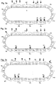
- FIGS. 3a to 3c show schematically a transport route 8 with ten groups or periods P1 - P10 each consisting of three stop positions for workpiece carrier sections, the stop positions in each stop position period being numbered with the stop position numbers 1-3, so that the stop position numbers 1, 2, 3 occur ten times.
- the stop positions are distributed equidistantly along the first transport path 8, just as workpiece carrier sections (not shown) are accordingly evenly distributed along the first transport path 8.
- the stop position numbers and the workpiece carrier section numbers are always mapped 1: 1 to one another in this model, so that at the stop positions with the stop position number 1 only workpiece carrier sections with the workpiece carrier section number 1 are held, at the stop positions with the stop position number 2 only workpiece carrier sections with the workpiece carrier section number 2 are held and only workpiece carrier sections with workpiece carrier section number 3 stop at the stop positions with stop position number 3. (This can be generalized for any positive whole number n in the case of n existing assembly devices with a corresponding adaptation of the step size and position period or workpiece carrier section group).
- the 3 mounting devices in the Figures 3a to 3c are distributed in their assignment to stop positions of the workpiece carrier sections along the first transport path via stop positions with the numbers 1 to 3, with a respective assembly device for each stop position number. If a mounting device is assigned to a stop position with a specific stop position number in a stop position period, no mounting device is assigned to the same stop position number of another stop position period. This results in various options for positioning the three mounting devices, three of which are in the Figures 3a to 3c are indicated by the double arrows 18, 20, 21.
- the assembly devices represented by the double arrows 18, 20, 21 are distributed over three successive stop position periods P1, P2, P3, whereby in this case, too, when a assembly device is assigned to a stop position number, no further assignment of an assembly device to the same stop position number in a different stop position period P. occurs. Since in this example the Figure 3b If the assembly device represented by the double arrow 18 is already assigned to the stop position number 1 in the stop position period P1, it does not happen that the stop position number 1 is assigned to a further assembly device of the type considered here in any other stop position period P.
- FIG. 3c Another example of the distribution of the mounting devices is shown, in this example the stop position number 1 in the stop position period P1 is assigned a mounting device (represented there by the double arrow 18), whereas the stop position numbers 2 and 3 in the stop position period P3 each have a mounting device (there by the double arrows 20 and 21 respectively) is assigned.
- transfer devices for supplying first component components to workpiece carrier sections can be distributed at relevant stop positions, as shown in FIG Figures 3a to 3c is also indicated on the basis of three examples, the transfer devices being represented by the arrows U1, U2, U3 pointing from the outside to the stop positions.
- the number of transfer devices corresponds to the number n of assembly devices.
- discharge devices for removing and diverting finished components or the like from relevant workpiece carrier sections can also be distributed at relevant stop positions, as shown in FIGS Figures 3a to 3c is also indicated on the basis of three examples, the dispensing devices being represented by arrows A1, A2, A3 pointing outward from the stop positions.
- the number of dispensing devices corresponds to the number n of assembly devices.
- the exemplary embodiments of the invention explained above with reference to the figures are those in which the first transport device was operated in a clocked, intermittent, that is, discontinuous, mode. As explained above, correspondingly constructed devices according to the invention can also be set up for continuous operation of the first transport device.
Landscapes
- Engineering & Computer Science (AREA)
- Mechanical Engineering (AREA)
- Manufacturing & Machinery (AREA)
- Automatic Assembly (AREA)
Description
Die Erfindung betrifft eine Vorrichtung mit den Merkmalen des Oberbegriffs von Anspruch 1 oder den Merkmalen des Oberbegriffs von Anspruch 2 zur Herstellung von Bauteilen aus jeweils wenigstens zwei Bauteilkomponenten in Serienfertigung.The invention relates to a device with the features of the preamble of
Es sind Vorrichtungen zur Herstellung eines Bauteils aus Bauteilkomponenten in Serienfertigung in diversen Varianten bekannt, welche eine Montagevorrichtung zum Zusammenfügen von ersten Bauteilkomponenten und zweiten Bauteilkomponenten umfassen und ferner Transporteinrichtungen zum Zuführen der ersten Bauteilkomponente und der zweiten Bauteilkomponente zu der Montagevorrichtung aufweisen. Das Zuführen der Bauteilkomponenten erfolgt üblicherweise in einem Transporttakt oder Maschinentakt, so dass jeweils eine erste Bauteilkomponente auf einem Werkstückträger zur Montagevorrichtung bewegt wird und dort im Wesentlichen synchron die zugeordnete zweite Bauteilkomponente ankommt, so dass im entsprechenden Maschinentakt die zweite Bauteilkomponente mit der ersten Bauteilkomponente mittels der Montagevorrichtung verbunden werden kann. Nach Verbinden einer zweiten Bauteilkomponente mit einer zugeordneten ersten Bauteilkomponente (oder ggf. auch mit noch weiteren Bauteilkomponenten) wird dieser Bauteilkomponentenverbund mittels der betreffenden Transporteinrichtung aus dem Bereich der Montagevorrichtung abtransportiert, um Platz für nachrückende Bauteilkomponenten zu machen, die miteinander zu verbinden sind. Bei den auf diese Art und Weise herzustellenden Bauteilen handelt es sich oft um Mehrkomponenten-Kleinbauteile, wie z.B. in Isolationsnestern eingebettete elektrische Schaltkontaktelemente oder SMD-Bauteile (surface mounted devices) für elektronische Geräte oder dergleichen. Bei den Bauteilkomponenten kann es sich um Bauteilkomponenten aus unterschiedlichen Materialien oder/und unterschiedlichen Formen oder/und unterschiedlichen Dimensionen handeln. Ein Beispiel könnte ein elektrischer Kontakt in einem Kunststoffhalter sein, wobei der Kunststoffhalter eine erste Bauteilkomponente und der elektrische Kontakt eine zweite Bauteilkomponente im vorstehend erläuterten Sinne darstellen könnte.Devices for producing a component from component components in series production in various variants are known which include an assembly device for joining first component components and second component components and also have transport devices for feeding the first component component and the second component component to the assembly device. The component components are usually supplied in a transport cycle or machine cycle, so that in each case a first component component is moved on a workpiece carrier to the assembly device and the assigned second component component arrives there essentially synchronously, so that in the corresponding machine cycle the second component component with the first component component by means of the Mounting device can be connected. After connecting a second component with an assigned first component (or possibly also with further component components), this component assembly is transported away from the area of the assembly device by means of the relevant transport device in order to make space for component components that are to be connected to one another. In the manufactured in this manner components are often multi-component-free components, such as in insulating nests embedded electrical switching contact elements or SMD components (s urface m ounted D evices) for electronic devices or like that. The component components can be component components made of different materials and / or different shapes and / or different dimensions. An example could be an electrical contact in a plastic holder, wherein the plastic holder could represent a first component component and the electrical contact could represent a second component component in the sense explained above.
Derartige Mehrkomponenten-Kleinbauteile werden oft in großer Stückzahl in Hochgeschwindigkeitsserienfertigung hergestellt, nämlich insbesondere dann, wenn Bedarf nach großen Mengen solcher Bauteile und hoher Kostendruck in Bezug auf deren Herstellung besteht.Such multi-component small components are often produced in large numbers in high-speed series production, namely especially when there is a need for large quantities of such components and high cost pressure with regard to their production.
Eine gattungsgemäße Vorrichtung mit den Merkmalen des Oberbegriffs von Anspruch 1 und des Oberbegriffs von Anspruch 2 ist aus der
Genauer wird in der
Vor diesem Hintergrund besteht die Aufgabe der vorliegenden Erfindung darin, eine Steigerung der Produktivität einer gattungsgemäßen Vorrichtung zur Herstellung von Bauteilen aus jeweils wenigstens zwei Bauteilkomponenten zu ermöglichen, wobei jede einzelne der Montagevorrichtungen die Bauteile herstellt.Against this background, the object of the present invention is to enable an increase in the productivity of a generic device for producing components from at least two component components, each of which is Assembly devices that manufacture components.
Zur Lösung dieser Aufgabe wird gemäß dem ersten Aspekt der Erfindung für den kontinuierlichen Transport eine Vorrichtung mit den Merkmalen von Anspruch 1 vorgeschlagen, gemäß dem zweiten Aspekt der Erfindung für den intermittierenden Transport eine Vorrichtung mit den Merkmalen von Anspruch 2.To solve this problem, according to the first aspect of the invention, a device with the features of
Es liegt im Rahmen der Erfindung, dass in unterschiedlichen Anwendungsfällen ersten Bauteilkomponenten unterschiedlich viele zweite Bauteilelemente zur gemeinsamen Verbindung zugeordnet sein können.It is within the scope of the invention that, in different application cases, first component components can be assigned a different number of second component elements for common connection.
Ein Ansatz der Erfindung besteht darin, n Montagevorrichtungen, also wenigstens zwei Montagevorrichtungen, entlang der ersten Transportstrecke zu positionieren, wobei diese Montagevorrichtungen die Aufgabe haben, erste Bauteilkomponenten und zweite Bauteilkomponenten vorzugsweise zeitgleich zu einem jeweiligen Verbund zusammenzufügen, und wobei die Montagevorrichtungen von ein und derselben ersten Transporteinrichtung mit ersten Bauteilkomponenten zeitgleich zu den Bereitstellungszeitpunkten der ersten Transporteinrichtung beliefert werden. Auf diese Weise kann die Anzahl der zu fertigenden Bauteile an einer ersten Transportstrecke erheblich vergrößert und die Maschinenproduktivität vervielfacht werden.One approach of the invention is to position n assembly devices, i.e. at least two assembly devices, along the first transport path, these assembly devices having the task of assembling first component components and second component components, preferably at the same time, to form a respective composite, and the assembly devices being one and the same first transport device are supplied with first component components at the same time as the provision times of the first transport device. In this way, the number of components to be produced on a first transport route can be increased considerably and machine productivity can be multiplied.
Auch liegt es im Rahmen der Erfindung, dass die erste Transporteinrichtung dazu eingerichtet sein kann, erste Bauteilkomponenten gruppenweise zu den Montagevorrichtungen zu transportieren, so dass zu den Bereitstellungszeitpunkten der ersten Transporteinrichtung eine jeweilige Gruppe aus ersten Bauteilkomponenten an jeder der Montagevorrichtungen zur im Wesentlichen simultanen Bearbeitung und/oder Übernahme durch die Montagevorrichtungen bereitsteht. Die zweite Transporteinrichtung stellt zu den Bereitstellungszeitpunkten der ersten Transporteinrichtung an den Montagevorrichtungen eine jeweilige Anzahl an zweiten Bauteilkomponenten bereit, die dem Bedarf an zweiten Bauteilkomponenten zum Zusammenfügen mit den ersten Bauteilkomponenten an den Montagevorrichtungen jeweils entspricht. Die Montagevorrichtungen sind dann so zu betreiben, dass sie in oder zwischen den Bereitstellungszeitpunkten der ersten Transporteinrichtung gleichzeitig Bauteilkomponenten der jeweiligen Gruppe aus ersten Bauteilkomponenten mit entsprechend zugeordneten zweiten Bauteilkomponenten verbinden können. Auch auf diese Weise kann die Produktivität der Vorrichtung zur Herstellung eines Bauteils aus wenigstens zwei Bauteilkomponenten in Serienfertigung gesteigert werden.It is also within the scope of the invention that the first transport device can be set up to transport first component components in groups to the assembly devices, so that at the times when the first transport device is made available, a respective group of first component components on each of the assembly devices for essentially simultaneous processing and / or is ready to be taken over by the assembly devices. The second transport device provides a respective number of second component components on the assembly devices at the times at which the first transport device is made available ready, which corresponds to the need for second component components for assembling with the first component components on the assembly devices. The assembly devices are then to be operated in such a way that they can simultaneously connect component components of the respective group of first component components with correspondingly assigned second component components at or between the provision times of the first transport device. In this way, too, the productivity of the device for producing a component from at least two component components in series production can be increased.
Die erste Transportstrecke ist eine geschlossene Endlosstrecke bzw. Schlaufe, wobei die erste Transporteinrichtung längs der ersten Transportstrecke zumindest näherungsweise äquidistant aufeinanderfolgende Werkstückträgerabschnitte umfasst und dazu eingerichtet ist, diese umlaufend entlang der ersten Transportstrecke zu bewegen, und wobei die Werkstückträgerabschnitte einzeln dazu eingerichtet sind, eine jeweilige erste Bauteilkomponente oder ggf. eine jeweilige Gruppe an ersten Bauteilkomponenten zum Transport aufzunehmen und längs der ersten Transportstrecke entsprechend der Transportbewegung der ersten Transporteinrichtung zu bewegen, wobei zumindest in einem bestimmten Streckenabschnitt der ersten Transportstrecke die Abstände zwischen den Positionen der Montagevorrichtungen längs der ersten Transportstrecke dem Abstand x zwischen gleichartigen Stellen, vorzugsweise den Mitten zweier unmittelbar aufeinander folgender Werkstückträgerabschnitte längs der ersten Transportstrecke oder einem ganzzahligen Vielfachen davon entsprechen, so dass eine auf den Abstand x abgestimmte Vorschubbewegung der Werkstückträgerabschnitte durch die erste Transporteinrichtung gewählt werden kann, um zu jedem Bereitstellungszeitpunkt alle n Montagevorrichtungen mit einer ersten Bauteilkomponente oder ggf. einer Gruppe erster Bauteilkomponenten zu beliefern. Auf diese Weise kann der Transport- und Transportsteuerungsaufwand bei der Zuführung von ersten Bauteilkomponenten zu den Montagevorrichtungen gering gehalten werden.The first transport path is a closed endless path or loop, the first transport device comprising workpiece carrier sections following at least approximately equidistantly along the first transport path and being configured to move them circumferentially along the first transport path, and wherein the workpiece carrier sections are individually configured to each Pick up the first component component or possibly a respective group of first component components for transport and move it along the first transport path in accordance with the transport movement of the first transport device, the distances between the positions of the assembly devices along the first transport path being the distance at least in a certain section of the first transport path x between similar locations, preferably the centers of two directly successive workpiece carrier sections along the first transport path or correspond to an integer multiple thereof, so that a feed movement of the workpiece carrier sections coordinated with the distance x by the first transport device can be selected in order to supply all n assembly devices with a first component component or, if necessary, a group of first component components at each provision time. In this way, the transport and transport control effort in the supply of the first Component components to the assembly devices are kept low.
Bei den Werkstückträgerabschnitten handelt es sich vorzugsweise um Halter, die so ausgeformt sind, dass sie erste Bauteilkomponenten oder ggf. Gruppen von ersten Bauteilkomponenten in einer gewünschten relativen Ausrichtung für den Transport längs der ersten Transportstrecke aufnehmen können, und die äquidistant in Reihe an einem Endlosband angeordnet sind, welches von der ersten Transporteinrichtung umlaufend längs der ersten Transportstrecke bewegt wird, um stets einen jeweiligen Werkstückträgerabschnitt mit einer ersten Bauteilkomponente oder ggf. Gruppe von ersten Bauteilkomponenten zu den Bereitstellungszeitpunkten an den Montagevorrichtungen gleichzeitig bereitzustellen.The workpiece carrier sections are preferably holders that are shaped so that they can accommodate first component components or possibly groups of first component components in a desired relative orientation for transport along the first transport path, and which are arranged equidistantly in series on an endless belt which is moved circumferentially by the first transport device along the first transport path in order to always provide a respective workpiece carrier section with a first component component or possibly a group of first component components at the times of provision on the assembly devices at the same time.
Je nach Ausführungsform der Erfindung kann die erste Transporteinrichtung dazu eingerichtet sein, die ersten Bauteilkomponenten bzw. die Werkstückträgerabschnitte kontinuierlich, vorzugsweise mit konstanter Geschwindigkeit, oder diskontinuierlich bzw. getaktet intermittierend zu bewegen. Auch kann eine Vorrichtung nach der Erfindung für den wahlweise kontinuierlichen oder diskontinuierlichen Transportbetrieb der ersten Transporteinrichtung eingerichtet sein.Depending on the embodiment of the invention, the first transport device can be set up to move the first component components or the workpiece carrier sections continuously, preferably at a constant speed, or discontinuously or intermittently. A device according to the invention can also be set up for the optional continuous or discontinuous transport operation of the first transport device.
Gemäß dem ersten Aspekt der Erfindung ist es vorgesehen, dass die erste Transporteinrichtung die Werkstückträgerabschnitte kontinuierlich mit einer Vorschubgeschwindigkeit V längs der ersten Transportstrecke vorschiebt, wobei die Vorschubgeschwindigkeit V und die Abstände (D) zwischen den Positionen der Montagevorrichtungen längs der ersten Transportstrecke so aufeinander abgestimmt sind, dass im Betrieb der ersten Transporteinrichtung - zumindest nach einer Anlaufphase - an allen Montagevorrichtungen zu den Bereitstellungszeitpunkten der ersten Transporteinrichtung ein jeweiliger Werkstückträgerabschnitt bereitsteht, so dass bei einem Umlauf der ersten Transporteinrichtung seriell sämtliche Werkstückträgerabschnitte zu den Bereitstellungszeitpunkten an einer betreffenden Montagevorrichtung bereitgestellt werden, wobei kein Werkstückträgerabschnitt an mehr als einer Montagevorrichtung bereitgestellt wird. Die Montagevorrichtungen sind somit an ausgewählten Positionen längs der ersten Transportstrecke platziert, so dass bei einem vollständigen Umlauf der Werkstückträgerabschnitte längs der als Endlosstrecke gestalteten ersten Transportstrecke und bei entsprechend gewähltem Vorschub bei der Transportbewegung der ersten Transporteinrichtung jeder Werkstückträgerabschnitt nur einmal zur Bereitstellung erster Bauteilkomponenten an einer Montagevorrichtung zu einem betreffenden Bereitstellungszeitpunkt bereitsteht. Zu den übrigen Bereitstellungszeitpunkten befinden sich die Werkstückträgerabschnitte während des Umlaufs außerhalb des Zuordnungsbereiches der Montagevorrichtungen.According to the first aspect of the invention, it is provided that the first transport device advances the workpiece carrier sections continuously at a feed speed V along the first transport path, the feed speed V and the distances (D) between the positions of the assembly devices along the first transport path being coordinated with one another that during operation of the first transport device - at least after a start-up phase - a respective workpiece carrier section is available on all assembly devices at the times of provision of the first transport device, so that when the first transport device rotates all workpiece carrier sections serially at the times of provision at one relevant assembly device are provided, wherein no workpiece carrier portion is provided on more than one assembly device. The assembly devices are thus placed at selected positions along the first transport path, so that with a complete rotation of the workpiece carrier sections along the first transport path designed as an endless path and with a correspondingly selected feed rate during the transport movement of the first transport device, each workpiece carrier section only once to provide first component components on an assembly device is available at a relevant provision time. At the other times of readiness, the workpiece carrier sections are located outside the assignment area of the assembly devices during the cycle.
Im Falle einer zum kontinuierlichen Transport betriebenen ersten Transporteinrichtung kommen verschiedene Arbeitsweisen der Montagevorrichtungen infrage. So kann es in einem Fall vorgesehen sein, dass die ersten Bauteilkomponenten während des Vorgangs des Zusammenfügens der ersten und zweiten Bauteilkomponenten in ihren jeweiligen Werkstückträgerabschnitten verbleiben und dass die Montagevorrichtungen bei ihren Montagevorgängen des Zusammensetzens der Bauteilkomponenten der Bewegung der Werkstückträgerabschnitte über einen kleinen Streckenabschnitt während eines kurzen Zeitintervalls, welches für den Montagevorgang erforderlich ist, folgen. In einem anderen Fall kann es vorgesehen sein, dass die ersten Bauteilkomponenten zum Zwecke des Zusammenfügens der ersten und zweiten Bauteilkomponenten kurzzeitig und vorübergehend von den Werkstückträgerabschnitten separiert werden, wobei dies alles innerhalb eines kurzen Zeitintervalls, welches für den Montagevorgang erforderlich ist und in welchem der Werkstückträgerabschnitt der betreffenden Montagevorrichtung seit dem letzten Bereitstellungszeitpunkt zugeordnet ist, zu erfolgen hat. Transfermittel müssen in diesem Fall dazu eingerichtet sein, eine betreffende erste Bauteilkomponente zum Bereitstellungszeitpunkt aus ihrem Werkstückträgerabschnitt zu entnehmen und nach Bearbeitung durch die Montagevorrichtung wieder an den Werkstückträgerabschnitt zurückzugeben, nachdem dieser um einen kleinen Streckenabschnitt längs der ersten Transportstrecke weiterbewegt wurde.In the case of a first transport device operated for continuous transport, various modes of operation of the assembly devices come into question. In one case, it can be provided that the first component components remain in their respective workpiece carrier sections during the process of joining the first and second component components and that the assembly devices move the workpiece carrier sections over a short distance during their assembly processes of assembling the component components Follow the time interval required for the assembly process. In another case, it can be provided that the first component components are briefly and temporarily separated from the workpiece carrier sections for the purpose of joining the first and second component components, all this within a short time interval that is required for the assembly process and in which the workpiece carrier section has been assigned to the relevant assembly device since the last time it was made available. In this case, transfer means must be set up to include a relevant first To remove component components from their workpiece carrier section at the time of preparation and to return them to the workpiece carrier section after processing by the assembly device after the latter has been moved on by a small section along the first transport path.
Vorzugsweise ist bei einer Ausführungsform der Erfindung die erste Transporteinrichtung in der Weise im kontinuierlichen Modus betreibbar, dass die Bereitstellungszeitpunkte periodisch mit einem Zeitabstand Δt aufeinanderfolgen, wobei sie die Werkstückträgerabschnitte längs der ersten Transportstrecke mit einer vorzugsweise konstanten Vorschubgeschwindigkeit V kontinuierlich vorbewegt, die im Wesentlichen dem n-fachen Abstand x zwischen gleichartigen Stellen, vorzugsweise den Mitten zweier aufeinanderfolgender Werkstückträgerabschnitte längs der ersten Transportstrecke dividiert durch den Zeitabstand Δt zwischen zwei aufeinanderfolgenden Bereitstellungszeitpunkten entspricht, also: ![]()
![]()
Während des Zeitabstandes Δt werden somit Gruppen aus n aufeinander folgenden Werkstückträgerabschnitten (6) um eine Strecke S = n x in Transportrichtung vorbewegt, wobei n die Anzahl an Montagevorrichtungen ist.During the time interval Δt, groups of n consecutive workpiece carrier sections (6) are thus moved forward by a distance S = n x in the transport direction, where n is the number of assembly devices.
Gemäß dem zweiten Aspekt der Erfindung ist die Vorrichtung mit diskontinuierlichem Betrieb der ersten Transporteinrichtung betreibbar.According to the second aspect of the invention, the device can be operated with discontinuous operation of the first transport device.
Dies ermöglicht eine Arbeitsweise der Montagevorrichtungen an ruhenden, in den Werkstückträgerabschnitten verbleibenden ersten Bauteilkomponenten während der Stoppzeiten (Schrittpausen) der intermittierenden Transportbewegung.This enables the assembly devices to work on stationary first component components remaining in the workpiece carrier sections during the stop times (pauses) of the intermittent transport movement.
Diese Vorrichtung umfasst eine bestimmte Anzahl n (größer als 1) an Montagevorrichtungen zum Zusammenfügen erster Bauteilkomponenten und zweiter Bauteilkomponenten zu Bauteilen, eine erste Transporteinrichtung zum getaktet intermittierenden Transport erster Bauteilkomponenten zu den Montagevorrichtungen längs einer als geschlossene Endlosstrecke gestalteten ersten Transportstrecke, eine zweite Transporteinrichtung zum Transport zweiter Bauteilkomponenten zu den Montagevorrichtungen, wobei die erste Transporteinrichtung dazu eingerichtet ist, im Transporttakt wenigstens eine jeweilige erste Bauteilkomponente zu jeder Montagevorrichtung zu transportieren, so dass in Stoppzeiten der intermittierenden Transportbewegung der ersten Transporteinrichtung jeweils wenigstens eine erste Bauteilkomponente an jeder Montagevorrichtung zur im Wesentlichen simultanen Bearbeitung durch die Montagevorrichtungen bereitsteht, wobei die zweite Transporteinrichtung dazu eingerichtet ist, zu den Stoppzeiten der intermittierenden Transportbewegung der ersten Transporteinrichtung eine jeweilige Anzahl an zweiten Bauteilkomponenten an den Montagevorrichtungen bereitzustellen, die dem Bedarf an zweiten Bauteilkomponenten zum Zusammenfügen mit den ersten Bauteilkomponenten an den Montagevorrichtungen jeweils entspricht.This device comprises a certain number n (greater than 1) of assembly devices for assembling first component components and second component components to form components, a first transport device for the clocked, intermittent transport of first component components to the assembly devices along a first transport path designed as a closed endless path, a second transport device for transport second component components to the assembly devices, wherein the first transport device is set up to transport at least one respective first component component to each assembly device in the transport cycle, so that at least one first component component on each assembly device for essentially simultaneous processing during stop times of the intermittent transport movement of the first transport device is available by the assembly devices, wherein the second transport device is set up at the stop times to provide the intermittent transport movement of the first transport device with a respective number of second component components on the assembly devices, which corresponds to the need for second component components for joining with the first component components on the assembly devices.
Die erste Transporteinrichtung dieser Vorrichtung ist gemäß dem zweiten Aspekt der Erfindung dazu eingerichtet, die Werkstückträgerabschnitte getaktet intermittierend mit einer Schrittweite S längs der ersten Transportstrecke vorzubewegen, wobei die Abstände (D) zwischen den Positionen der Montagevorrichtungen längs der ersten Transportstrecke so aufeinander abgestimmt sind, dass im Betrieb der ersten Transporteinrichtung - zumindest nach einer Anlaufphase - an allen Montagevorrichtungen in den den Bereitstellungszeitpunkten der ersten Transporteinrichtung entsprechenden Stoppzeiten der intermittierenden Transportbewegung ein jeweiliger Werkstückträgerabschnitt bereitsteht, so dass bei einem Umlauf der ersten Transporteinrichtung seriell sämtliche Werkstückträgerabschnitte in den Stoppzeiten der intermittierenden Transportbewegung an einer betreffenden Montagevorrichtung bereitgestellt werden, wobei kein Werkstückträgerabschnitt an mehr als einer Montagevorrichtung bereitgestellt wird.According to the second aspect of the invention, the first transport device of this device is set up to move the workpiece carrier sections clocked intermittently with a step size S along the first transport path, the distances (D) between the positions of the assembly devices along the first transport path being coordinated with one another so that During operation of the first transport device - at least after a start-up phase - a respective workpiece carrier section is available at all assembly devices in the stop times of the intermittent transport movement corresponding to the provision times of the first transport device, so that when the first transport device rotates, all workpiece carrier sections serially in the stop times of the intermittent Transport movement are provided on a relevant assembly device, wherein no workpiece carrier portion is provided on more than one assembly device.
Hierzu ist die erste Transporteinrichtung vorzugsweise dazu eingerichtet, die Werkstückträgerabschnitte längs der ersten Transportstrecke mit einer Schrittweite S intermittierend fortzubewegen, die im Wesentlichen dem n-fachen Abstand x zwischen gleichartigen Stellen, vorzugsweise Mitten zweier aufeinanderfolgender Werkstückträgerabschnitte längs der ersten Transportstrecke oder einem ganzzahligen Vielfachen davon entspricht, so dass bei jedem Schritt Gruppen aus n aufeinander folgenden Werkstückträgerabschnitten um eine Strecke S = n x in Transportrichtung vorbewegt werden, wobei n die Anzahl an Montagevorrichtungen ist. Nummeriert man die Werkstückträgerabschnitte jeder Gruppe von 1 bis n durch, so sind jeder Nummer feste Stopppositionen längs der ersten Transportstrecke in dem Sinne zugeordnet, dass von sämtlichen Werkstückträgerabschnitten diejenigen mit der gleichen Nummer an jeweils gleichen Stopppositionen halten. In diesem Sinne können auch periodisch die Stopppositionen längs der ersten Transportstrecke durchnummeriert werden, wobei die Anzahl der Perioden der Anzahl der Gruppen von Werkstückträgerabschnitten entspricht. So kommen Werkstückträgerabschnitte mit einer bestimmten Nummer nur an den Stopppositionen mit der gleichen Nummer längs der ersten Transportstrecke zum Halt. Dies gilt für alle Werkstückträgerabschnitte. Die n Montagevorrichtungen sind in ihrer Zuordnung zu Stopppositionen der Werkstückträgerabschnitte längs der ersten Transportstrecke über Stopppositionen mit den Nummern 1 bis n verteilt, wobei auf eine jeweilige Stopppositionsnummer jeweils eine Montagevorrichtung kommt. Ist eine Montagevorrichtung einer Stoppposition mit einer bestimmten Stopppositionsnummer in einer Periode zugeordnet, so ist der gleichen Stopppositionsnummer einer anderen Periode keine Montagevorrichtung zugeordnet. Die Gesamtzahl der Stopppositionen entlang der ersten Transportstrecke soll durch n ohne Rest teilbar sein.For this purpose, the first transport device is preferably set up to intermittently move the workpiece carrier sections along the first transport path with an increment S which corresponds essentially to n-times the distance x between similar locations, preferably in the middle of two consecutive workpiece carrier sections along the first transport path or an integral multiple thereof , so that in each step groups of n consecutive workpiece carrier sections are moved forward by a distance S = nx in the transport direction, where n is the number of assembly devices. If the workpiece carrier sections of each group are numbered from 1 to n, fixed stop positions are assigned to each number along the first transport path in the sense that of all workpiece carrier sections those with the same number stop at the same stop positions. In this sense, the stop positions along the first transport path can also be numbered periodically, the number of periods corresponding to the number of groups of workpiece carrier sections. Workpiece carrier sections with a certain number only come to a stop at the stop positions with the same number along the first transport path. This applies to all workpiece carrier sections. The n assembly devices are distributed in their assignment to stop positions of the workpiece carrier sections along the first transport path via stop positions with the
Gemäß einer Ausführungsform der Erfindung sind zwei Montagevorrichtungen vorgesehen, so dass n = 2 und S = 2 x, wobei der Abstand (D) zwischen den Positionen der beiden Montagevorrichtungen längs der ersten Transportstrecke dem Abstand x zwischen gleichartigen Stellen, vorzugsweise Mitten, zweier aufeinanderfolgender Werkstückträgerabschnitte längs der ersten Transportstrecke oder einem ungeradzahligen Vielfachen davon entspricht.According to one embodiment of the invention, two assembly devices are provided so that n = 2 and S = 2 x, the distance (D) between the positions of the two assembly devices along the first transport path being the distance x between similar locations, preferably in the middle, of two consecutive workpiece carrier sections along the first transport route or an odd multiple thereof.
Aus Gründen optimierter Platzausnutzung ist es oft vorteilhaft, wenn die erste Transportstrecke wenigstens einen linearen Abschnitt aufweist, wobei die Montagevorrichtungen vorzugsweise an dem linearen Abschnitt der ersten Transportstrecke in Zuordnung zu betreffenden Stopppositionen der Werkstückträgerabschnitte positioniert sind. Besonders vorteilhaft in diesem Sinne ist es, wenn die erste Transportstrecke in Draufsichtsprojektion als Oval aus zwei durch lineare Abschnitte miteinander verbundenen Halbkreisbögen gebildet ist. Die linearen Abschnitte können dann sehr gut für eine platzoptimierte Positionierung der Montagevorrichtungen einerseits und von Übergabeeinrichtungen zur Übergabe von ersten Bauteilkomponenten zu Werkstückträgerabschnitten der ersten Transporteinrichtung andererseits sowie auch zur günstigen Positionierung von Ausbringeinrichtungen zum Ausbringen von Bauteilen aus den Werkstückträgerabschnitten und zum Ausschleusen der Bauteile aus der ersten Transporteinrichtung genutzt werden.For reasons of optimized space utilization, it is often advantageous if the first transport path has at least one linear section, the assembly devices preferably being positioned on the linear section of the first transport path in association with relevant stop positions of the workpiece carrier sections. In this sense, it is particularly advantageous if the first transport path is formed as an oval in plan projection from two semicircular arcs connected to one another by linear sections. The linear sections can then be used very well for a space-optimized positioning of the assembly devices on the one hand and of transfer devices for transferring first component components to workpiece carrier sections of the first transport device on the other hand, as well as for the favorable positioning of discharge devices for discharging components from the workpiece carrier sections and for discharging the components from the first Transport facility can be used.
Häufig handelt es sich zumindest bei den zweiten Bauteilkomponenten um winzige und/oder filigrane Stanzteile. Insbesondere im Rahmen einer solchen Anwendung ist es gemäß einer Ausgestaltung der Erfindung vorgesehen, die zweiten Bauteilkomponenten an einem diesen zugeordneten Haltestreifen zu bewegen, so dass zu den Stoppzeiten der intermittierenden Transportbewegung der ersten Transporteinrichtung an den Montagevorrichtungen stets eine jeweilige Anzahl an zweiten Bauteilkomponenten bereitstehen, die dem Bedarf an zweiten Bauteilkomponenten zum Zusammenfügen mit den ersten Bauteilkomponenten den Montagevorrichtungen jeweils entspricht. Bei diesen Haltestreifen und den daran angeordneten zweiten Bauteilkomponenten handelt es sich vorzugsweise um einen Stanzstreifen, bei dem der Haltestreifen und die zweiten Bauteilkomponenten stoffschlüssig zusammenhängen. Mit anderen Worten handelt es sich bei dem Haltestreifen um stoffschlüssig mit den zweiten Bauteilkomponenten zusammenhängenden Überbleibseln eines Rohmaterialstreifens, der einem Stanzprozess mittels einer Stanzpresse unterzogen worden ist, um die zweiten Bauteilkomponenten zu bilden. Eine solche Stanzpresse kann der Vorrichtung zur Herstellung eines Bauteils aus wenigstens zwei Bauteilkomponenten in Serienfertigung unmittelbar oder mittelbar vorgeschaltet sein, so dass der die Stanzpresse verlassende Stanzstreifen unmittelbar der Vorrichtung nach der Erfindung zugeführt wird. Ggf. kann zwischen einer solchen Stanzpresse und der Vorrichtung nach der Erfindung auch noch eine Umformvorrichtung zwischengeschaltet sein, etwa um die zweiten Bauteilkomponenten einem Biegeprozess zu unterziehen; oder etwa eine Schweißstation, um einen Kontakt aufzuschweißen. Solche Vorrichtungen können ggf. auch in die Vorrichtung nach der Erfindung integriert sein.Often at least the second component components are tiny and / or filigree stamped parts. In particular in the context of such an application, it is provided according to an embodiment of the invention to move the second component components on a holding strip assigned to them, so that at the stop times of the intermittent transport movement of the first transport device to the Assembly devices always have a respective number of second component components available, which corresponds to the need for second component components for assembly with the first component components of the assembly devices. These holding strips and the second component components arranged thereon are preferably a punched strip in which the holding strip and the second component components are cohesively connected. In other words, the holding strip is remnants of a raw material strip that are cohesively connected to the second component components and that has been subjected to a punching process by means of a punching press in order to form the second component components. Such a punch press can be connected directly or indirectly upstream of the device for producing a component from at least two component components in series production, so that the punch strip leaving the punch press is fed directly to the device according to the invention. Possibly. a forming device can also be interposed between such a punch press and the device according to the invention, for example in order to subject the second component components to a bending process; or a welding station to weld on a contact. Such devices can optionally also be integrated into the device according to the invention.
Die zweite Transporteinrichtung ist gemäß einer Ausführungsform der Erfindung mit an einem Haltestreifen zugeführten zweiten Bauteilkomponenten dazu eingerichtet, den Haltestreifen mit den daran angeordneten zweiten Bauteilkomponenten getaktet intermittierend vorzubewegen, wobei der Schritttakt der zweiten Transporteinrichtung und der Schritttakt der ersten Transporteinrichtung aufeinander abgestimmt, insbesondere synchronisiert sind. Eine solche Lösung ist sehr einfach zu realisieren. Die Folgedichte zweiter Bauteilkomponenten an dem Haltestreifen ist vorzugsweise so gewählt, dass nach jedem Schritt die jeweilige benötigte Menge an zweiten Bauteilkomponenten zur Weiterbearbeitung an den Montagevorrichtungen ansteht. Hierzu ist den Montagevorrichtungen jeweils eine Einrichtung zum Trennen der bereitgestellten zweiten Bauteilkomponenten von ihrem Haltestreifen zugeordnet. Die vereinzelten zweiten Bauteilkomponenten können dann mittels Übergabevorrichtungen bzw. Bestückungsautomaten der Montagevorrichtungen den Werkstückträgerabschnitten der ersten Transporteinrichtung zugeführt werden, um dort mit den bereitgestellten ersten Bauteilkomponenten vereinigt zu werden.According to one embodiment of the invention, with second component components supplied on a retaining strip, the second transport device is set up to intermittently move the retaining strip with the second component components arranged thereon, the step cycle of the second transport device and the step cycle of the first transport device being coordinated, in particular synchronized, with one another. Such a solution is very easy to implement. The subsequent density of the second component components on the holding strip is preferably selected so that after each step the respective required amount of second component components for further processing on the assembly devices is pending. For this purpose, the assembly devices are each assigned a device for separating the provided second component components from their holding strips. The separated second component components can then be fed to the workpiece carrier sections of the first transport device by means of transfer devices or automatic placement machines of the assembly devices in order to be combined there with the provided first component components.
Gemäß einer weiteren vorteilhaften Ausgestaltung der Erfindung mit an einem Haltestreifen, vorzugsweise Stanzstreifen, zugeführten zweiten Bauteilkomponenten, ist es vorgesehen, dass der Haltestreifen eine Längsteilung in der Weise aufweist, dass er zwei gesonderte, in Streifenlängsrichtung verlaufende Randsaumstreifenabschnitte hat, deren Abstand quer zur Streifenlängsrichtung im Wesentlichen konstant ist und deren jeder einen Haltestreifenrandabschnitt bildet, von dem jeweilige zweite Bauteilkomponenten in Streifenlängsrichtung aufeinanderfolgend mit Freiräumen dazwischen quer zur Streifenlängsrichtung abstehen, derart, dass die zweiten Bauteilkomponenten des einen Haltestreifens in die Freiräume der Bauteilkomponenten des anderen Haltestreifens hineinragen.According to a further advantageous embodiment of the invention with second component components fed to a holding strip, preferably punched strip, it is provided that the holding strip has a longitudinal division in such a way that it has two separate edge strip sections running in the longitudinal direction of the strip, the distance between them being transverse to the longitudinal direction of the strip Is essentially constant and each of which forms a retaining strip edge section from which respective second component components protrude in the longitudinal direction of the strip successively with free spaces in between transversely to the longitudinal direction of the strip, in such a way that the second component components of one retaining strip protrude into the free spaces of the component components of the other retaining strip.
Eine solche Lösung ermöglicht in vielen Fällen eine größere Folgedichte aufeinander folgender zweiter Bauteilkomponenten an dem Haltestreifen bei sehr geringem Verschnitt etwa beim Stanzen oder einem anderen Materialtrennvorgang an einem betreffenden Rohmaterialstreifen.In many cases, such a solution enables a greater density of consecutive second component components on the holding strip with very little waste, for example during punching or another material separation process on a relevant raw material strip.
Der ersten Transporteinrichtung ist gemäß einer bevorzugten Ausführungsform der Erfindung wenigstens eine Übergabevorrichtung zugeordnet, die dazu eingerichtet ist, erste Bauteilkomponenten den Werkstückträgerabschnitten der ersten Transporteinrichtung zuzuführen, so dass jeder Werkstückträgerabschnitt eine mittels der ersten Transporteinrichtung zu den Montagevorrichtungen zu transportierende jeweilige Anzahl an ersten Bauteilkomponenten erhält. Entsprechend kann auch eine Ausbringvorrichtung zum Ausbringen von zusammengesetzten Bauteilen aus den Werkstückträgerabschnitten und der ersten Transportstrecke vorgesehen sein.According to a preferred embodiment of the invention, at least one transfer device is assigned to the first transport device, which is set up to feed first component components to the workpiece carrier sections of the first transport device, so that each workpiece carrier section can receive one by means of the first Transport device to be transported to the assembly devices receives the respective number of first component components. Correspondingly, a discharge device can also be provided for discharging assembled components from the workpiece carrier sections and the first transport path.
Ausführungsbeispiele der Erfindung werden nachstehend unter Bezugnahme auf die Figuren näher erläutert.
Figur 1- zeigt in einer schematischen Draufsichtsdarstellung ein erstes Ausführungsbeispiel der Erfindung.
Figur 2- zeigt in einer schematischen Draufsichtsdarstellung ein zweites Ausführungsbeispiel der Erfindung.
- Figur 3a bis 3c
- zeigen in schematischen Darstellungen eine erste Transportstrecke mit periodisch durchnummerierten Stopppositionen für Werkstückträgerabschnitte mit unterschiedlichen Möglichkeiten der Positionierung von Montagevorrichtungen.
- Figure 1
- shows a first embodiment of the invention in a schematic plan view.
- Figure 2
- shows a second exemplary embodiment of the invention in a schematic plan view.
- Figures 3a to 3c
- show in schematic representations a first transport path with periodically numbered stop positions for workpiece carrier sections with different possibilities for positioning assembly devices.
In
Die beiden Übergabevorrichtungen 14, 15 sind so dem Abstand x angepasst angeordnet, dass sie simultan jeweils zwei aufeinanderfolgende Werkstückträgerabschnitte 6 während der Stoppzeiten der intermittierenden Transportbewegung der ersten Transporteinrichtung 2 mit Kontaktgehäusepaaren 12, 12, bestücken können.The two
In jedem Transporttakt der ersten Transporteinrichtung 2 werden somit zwei aufeinanderfolgende Werkstückträgerabschnitte 6 mit ersten Bauteilkomponenten 12 bestückt, so dass die Bauteilkomponenten 12 in einer vorbestimmten Position relativ zu dem betreffenden Werkstückträgerabschnitt 6 an diesem vorübergehend angeordnet werden.In each transport cycle of the
Die Transportbewegung der ersten Transporteinrichtung 2 läuft gesteuert ab, wobei die Schrittweite S eines Transportschrittes dem doppelten Abstand x zwischen zwei aufeinanderfolgenden Werkstückträgerabschnitten 6 entspricht. Auf diese Weise wird sichergestellt, dass den Übergabevorrichtungen 14, 15 nach jedem Transportschritt der ersten Transporteinrichtung 2 zwei aufeinander folgende leere Werkstückträgerabschnitte 6 zur Bestückung mit ersten Bauteilkomponenten 12 gegenüber stehen.The transport movement of the
Die mit den ersten Bauteilkomponenten 12 bestückten Werkstückträgerabschnitte 6 werden - von den Übergabevorrichtungen 14, 15 kommend - längs der ersten Transportstrecke 8 schrittweise mit der Schrittweite S weitertransportiert, so dass sie in den in
Bei den zweiten Bauteilkomponenten 22 handelt es sich im Beispielsfall um Stanzteile aus einem metallischen Kontaktmaterial, die an einem Haltestreifen 24 längs einer zweiten Transportstrecke 26, die im Beispielsfall (in Draufsichtsprojektion) parallel zu dem unteren linearen Abschnitt 16 der ersten Transportstrecke 8 verläuft, den Montagevorrichtungen 18, 20 zugeführt werden. Eine zweite Transporteinrichtung ist in
Mit 36 ist in
Die zweite Transporteinrichtung 30 - 32 ist dazu eingerichtet, in einem Transporttakt entsprechend dem Transporttakt der ersten Transporteinrichtung 2 den Montagevorrichtungen 18, 20 jeweils so viele zweite Bauteilkomponenten 22 bereitzustellen, wie es für die Soll-Bestückung erster Bauteilkomponenten 12 mit zweiten Bauteilkomponenten 22 durch die Montagevorrichtungen 18, 20 während jeder Stoppphase der intermittierenden Bewegung der ersten Transporteinrichtung 2 erforderlich ist.The second transport device 30-32 is set up to provide the
Der Abstand D zwischen den Montagevorrichtungen 18, 20 entspricht in dem Beispielsfall gemäß
Das Ausführungsbeispiel gemäß
Bei dem Ausführungsbeispiel nach
An den Montagevorrichtungen 18 und 20 werden die ersten Bauteilkomponenten 12 wiederrum mit zweiten Bauteilkomponenten 22 vereinigt.On the
Auch die zweiten Bauteilkomponenten 22 sind Stanzteile, die an Haltestreifenabschnitten 24 a und 24 b längs der zweiten Transportstrecke 26 mittels einer zweiten Transporteinrichtung 30 - 32 bewegt werden. Abweichend von dem Haltestreifen mit zweiten Bauteilkomponenten aus
Bei den vorstehend unter Bezugnahme auf die
Dabei ist es vorteilhaft, oben bereits erwähnte Gesetzmäßigkeiten bei der Positionierung der Montagevorrichtungen längs der ersten Transportstrecke und dem Betrieb der ersten Transporteinrichtung zu berücksichtigen.It is advantageous here to take into account the above-mentioned regularities in the positioning of the assembly devices along the first transport route and the operation of the first transport device.
Eine dieser Gesetzmäßigkeiten betrifft die Schrittweite S der intermittierenden Vorschubtransportbewegung der ersten Transporteinrichtung. S = n x , wobei n die Anzahl der Montagevorrichtungen - und x der Mittenabstand zwischen zwei unmittelbar aufeinander folgenden Werkstückträgerabschnitten ist, wobei vorausgesetzt ist, dass die Werkstückträgerabschnitte im Wesentlichen äquidistant aufeinanderfolgend längs der ersten Endlos-Transportstrecke 8 verteilt sind.One of these regularities relates to the step size S of the intermittent feed transport movement of the first transport device. S = n x, where n is the number of assembly devices - and x is the center-to-center distance between two directly successive workpiece carrier sections, it being assumed that the workpiece carrier sections are distributed essentially equidistantly one after the other along the first
Dementsprechend wurde bei den bereits beschriebenen Ausführungsbeispielen mit zwei Montagevorrichtungen 18, 20 eine Schrittweite S = 2x gewählt.Correspondingly, in the exemplary embodiments already described with two mounting
Unter Bezugnahme auf die
Die
Die Anzahl der Stopppositionen in jeder Stopppositionsperiode P1 - P10 soll der Anzahl n der Montagevorrichtungen entsprechen, dies ist im Beispielsfall der
Die erste Transporteinrichtung ist dazu eingerichtet, bei jedem Schritt ihrer intermittierenden Transportbewegung Gruppen aus 3 aufeinander folgenden Werkstückträgerabschnitten um eine Strecke S = 3 x in Transportrichtung (beispielsweise im Uhrzeigersinn) vorzubewegen. Nummeriert man auch die Werkstückträgerabschnitte jeder Gruppe von 1 bis 3 durch, so kann jeder Stopppositionsnummer längs der ersten Transportstrecke 8 eine gleiche Werkstückträgerabschnittsnummer in dem Sinne zugeordnet werden, dass von sämtlichen Werkstückträgerabschnitten diejenigen mit der gleichen Werkstückträgerabschnittsnummer an Stopppositionen mit der entsprechend gleichen Stopppositionsnummer halten, d.h. die Stopppositionsnummern und die Werkstückträgerabschnittsnummern sind bei diesem Modell stets 1:1 aufeinander abgebildet, so dass an den Stopppositionen mit der Stopppositionsnummer 1 nur Werkstückträgerabschnitte mit der Werkstückträgerabschnittsnummer 1 zum Halten kommen, an den Stopppositionen mit der Stopppositionsnummer 2 nur Werkstückträgerabschnitte mit der Werkstückträgerabschnittsnummer 2 zum Halten kommen und an den Stopppositionen mit der Stopppositionsnummer 3 nur Werkstückträgerabschnitte mit der Werkstückträgerabschnittsnummer 3 zum Halten kommen. (Dies ist für eine beliebige positive ganze Zahl n im Falle von n vorhandenen Montagevorrichtungen bei entsprechender Schrittweiten- und Positionsperioden- bzw. Werkstückträgerabschnittsgruppenanpassung verallgemeinerbar).The first transport device is set up to move groups of 3 consecutive workpiece carrier sections forward by a distance S = 3 x in the transport direction (for example clockwise) with each step of its intermittent transport movement. If the workpiece carrier sections of each group are numbered from 1 to 3, each stop position number along the
Die 3 Montagevorrichtungen in den
In
In
In
Nach dem unter Bezugnahme auf die
Es ist derzeit bevorzugt, die Montagevorrichtungen an einem linearen Abschnitt der ersten Transportstrecke 8 unterzubringen, was nicht bedeutet, dass Montagevorrichtungen nicht auch oder ausschließlich an gekrümmten Abschnitten der ersten Transportstrecke 8 vorgesehen sein können.It is currently preferred to accommodate the assembly devices on a linear section of the
Nach dem gleichen Schema können auch Übergabevorrichtungen zur Zuführung von ersten Bauteilkomponenten zu Werkstückträgerabschnitten an betreffenden Stopppositionen verteilt werden, wie dies in den
Nach dem gleichen Schema können auch Ausbringvorrichtungen zum Entfernen und Ableiten von fertigen Bauteilen oder dergleichen von betreffenden Werkstückträgerabschnitten an betreffenden Stopppositionen verteilt werden, wie dies in den
Bei den vorstehend unter Bezugnahme auf die Figuren erläuterten Ausführungsbeispielen der Erfindung handelt es sich um solche, bei denen die erste Transporteinrichtung in einem getaktet intermittierenden, also diskontinuierlichen Modus betrieben wurde. Wie oben dargelegt, können entsprechend aufgebaute Vorrichtungen nach der Erfindung auch für einen kontinuierlich durchlaufenden Betrieb der ersten Transporteinrichtung eingerichtet sein.The exemplary embodiments of the invention explained above with reference to the figures are those in which the first transport device was operated in a clocked, intermittent, that is, discontinuous, mode. As explained above, correspondingly constructed devices according to the invention can also be set up for continuous operation of the first transport device.
Einem Schritt der intermittierenden Bewegung mit der Schrittweite S der vorstehend unter Bezugnahme auf die Figuren erläuterten Ausführungsbeispiele entspricht bei einer bevorzugten Ausführungsform der Erfindung mit kontinuierlichem Transportbetrieb mit konstanter Vorschubgeschwindigkeit V der ersten Transporteinrichtung einer jeweils zurückgelegten Strecke S, deren Länge sich aus dem Produkt aus der Vorschubgeschwindigkeit V der ersten Transporteinrichtung und dem Zeitabstand Δt zwischen zwei unmittelbar aufeinanderfolgenden Bereitstellungszeitpunkten der ersten Transporteinrichtung ergibt: ![]()
- wobei n der Anzahl der vorgesehenen Montagevorrichtungen-
- und x der Mittenabstand zweier aufeinanderfolgender Werkstückträgerabschnitte ist. n und x stehen somit für normalerweise gegebene geometrische Parameter der Vorrichtung. Der Zeitabstand Δt steht normalerweise auch fest. Die für einen optimalen Betrieb der Vorrichtung erforderliche Vorschubgeschwindigkeit V der ersten Transporteinrichtung kann dann bei gegebenem Zeitabstand Δt zwischen zwei aufeinander folgenden Bereitstellungszeitpunkten aus der obigen Gleichung durch Umstellung ermittelt werden:

- where n is the number of assembly devices provided
- and x is the center-to-center distance of two consecutive workpiece carrier sections. n and x therefore stand for normally given geometric parameters of the device. The time interval Δt is usually also fixed. The feed speed V of the first transport device required for optimal operation of the device can then be determined from the above equation by adjusting for a given time interval Δt between two successive provision times:
Claims (13)
- Device for producing components (40) from at least two component parts (12, 22) in serial production, comprising- a certain number n>1 of assembly devices (18, 20) for fitting together first component parts (12) and second component parts (22) so as to form components (40),- a first transport means (2) which is designed to transport first component parts (12) to the assembly devices (18, 20) along a first transport path (8), designed as a closed, continuous path, such that, at certain successive provision times of the first transport means (2), at least one first component part (12) is made available to all of the assembly devices (18, 20) so as to be substantially simultaneously received and/or processed by the assembly devices (18, 20),- a second transport means (30-32) which is designed to transport second component parts (22) to the assembly devices (18, 20) in such a way that, at the provision times of the first transport means (2), a particular number of second component parts (22) are made available to the assembly devices (18, 20), which number meets in each case the need for second component parts (22) for being fitted together with the first component parts (12) at the assembly devices (18, 20),
the first transport means (2) comprising workpiece carrier portions (6) that are arranged successively at approximately equidistant points along the first transport path (8), and being designed to move said portions in a circulating manner along the first transport path (8), the workpiece carrier portions (6) being individually designed to each hold a particular first component part (12), or optionally a particular group of first component parts (12), for the transport thereof, and to move said component part or group of component parts along the first transport path (8) according to the transport movement of the first transport means (2), the distances between the positions of the assembly devices (18, 20) along the first transport path (8), at least in a certain stretch of the first transport path (8), corresponding to the distance (x) between similar locations, preferably the centres of two successive workpiece carrier portions (6), along the first transport path (8), or to an integral multiple thereof,
characterised in that the first transport means (2) is designed to continuously advance the workpiece carrier portions (6) along the first transport path (8) at a feed speed (V), the feed speed (V) and the distances (D) between the positions of the assembly devices (18, 20) along the first transport path (8) being matched to one another such that, during operation of the first transport means (2), at least after a start-up phase, one particular workpiece carrier portion (6) is made available to all of the assembly devices (18, 20) at the provision times of the first transport means (2) such that, when the first transport means (2) is circulating, the workpiece carrier portions (6) are each provided, in series, to a relevant assembly device (18, 20) at a particular provision time, with no workpiece carrier portion (6) being provided to more than one assembly device (18, 20). - Device for producing components (40) from at least two component parts (12, 22) in serial production, comprising- a certain number n>1 of assembly devices (18, 20) for fitting together first component parts (12) and second component parts (22) so as to form components (40),- a first transport means (2) which is designed to transport first component parts (12) to the assembly devices (18, 20) along a first transport path (8), designed as a closed, continuous path, such that, at certain successive provision times of the first transport means (2), at least one first component part (12) is made available to all of the assembly devices (18, 20) so as to be substantially simultaneously received and/or processed by the assembly devices (18, 20),- a second transport means (30-32) which is designed to transport second component parts (22) to the assembly devices (18, 20) in such a way that, at the provision times of the first transport means (2), a particular number of second component parts (22) are made available to the assembly devices (18, 20), which number meets in each case the need for second component parts (22) for being fitted together with the first component parts (12) at the assembly devices (18, 20),
the first transport means (2) comprising workpiece carrier portions (6) that are arranged successively at approximately equidistant points along the first transport path (8), and being designed to move said portions in a circulating manner along the first transport path (8), the workpiece carrier portions (6) being individually designed to each hold a particular first component part (12), or optionally a particular group of first component parts (12), for the transport thereof, and to move said component part or group of component parts along the first transport path (8) according to the transport movement of the first transport means (2), the distances between the positions of the assembly devices (18, 20) along the first transport path (8), at least in a certain stretch of the first transport path (8), corresponding to the distance (x) between similar locations, preferably the centres of two successive workpiece carrier portions (6), along the first transport path (8), or to an integral multiple thereof, the first transport means (2) being designed to move the workpiece carrier portions (6) along the first transport path (8) intermittently, in cycles, in a specified increment (S),
characterised in that the distances (D) between the positions of the assembly devices (18, 20) along the first transport path (8) are matched to one another such that, during operation of the first transport means (2), at least after a start-up phase, one particular workpiece carrier portion (6) is made available to all of the assembly devices (18, 20) within the stop times of the intermittent transport movement that correspond to the provision times of the first transport means (2) such that, when the first transport means (2) is circulating, the workpiece carrier portions (6) are each provided, in series, to a relevant assembly device (18, 20) within a particular stop time of the intermittent transport movement, with no workpiece carrier portion (6) being provided to more than one assembly device (18, 20). - Device for producing components from at least two component parts in serial production according to either claim 1 or claim 2, characterised in that the first transport means (2) is designed to transport first component parts (12) to the assembly devices (18, 20) in groups such that, at the provision times of the first transport means (2), one particular group of first component parts (12) is made available to each of the assembly devices (18, 20) so as to be substantially simultaneously processed by the assembly devices (18, 20).
- Device for producing components from at least two component parts in serial production according to claim 1 or claim 3 in combination with claim 1, characterised in that the provision times of the first transport means (2) successively follow one another periodically at a time interval Δt, the first transport means (2) being designed to continuously move the workpiece carrier portions (6) along the first transport path (2) at a preferably constant feed speed V which corresponds substantially to n times the distance x between similar locations, preferably the centres of two successive workpiece carrier portions (6), along the first transport path (8) divided by the time interval Δt between two successive provision times, i.e.:
V = nx / Δt, such that, during the time interval Δt, groups of n successive workpiece carrier portions (6) are moved in the transport direction by a distance S = n x, where n is the number of assembly devices. - Device for producing components from at least two component parts in serial production according to claim 2 or claim 3 in combination with claim 2, characterised in that the increment S of the intermittent transport movement of the first transport means (2) substantially corresponds to n times the distance x between similar locations, preferably the centres of two successive workpiece carrier portions (6), along the first transport path (8) such that, in each step, groups of n successive workpiece carrier portions (6) are moved in the transport direction by a distance S = n x, where n is the number of assembly devices.
- Device for producing components from at least two component parts in serial production according to any of the preceding claims, characterised in that two assembly devices (18, 20) are provided such that the distance (D) between the positions of the two assembly devices (18, 20) along the first transport path (8) corresponds to the distance x between similar locations, preferably the centres of two successive workpiece carrier portions (6), along the first transport path (8), or to an odd multiple thereof.
- Device for producing components from at least two component parts in serial production according to any of the preceding claims, characterised in that the first transport path (8) has at least one linear portion (16), and in that the assembly devices (18, 20) are positioned on the at least one linear portion (16) of the first transport path (8).
- Device for producing components from at least two component parts in serial production according to any of the preceding claims, characterised in that the second transport means (30-32) is designed to move second component parts (22) on a holding strip (24; 24a, 24b) associated with said component parts such that, at the provision times of the first transport means (2), a particular number of second component parts (22) is always made available to the assembly devices (18, 20), which number meets in each case the need for second component parts (22) for being fitted together with the first component parts (12) at the assembly devices (18, 20).
- Device for producing components from at least two component parts in serial production according to claim 8, characterised in that the holding strip (24; 24a, 24b) together with the second component parts (22) arranged thereon is a stamped strip in which the holding strip (24; 24a, 24b) and the second component parts (22) are integrally bonded together.
- Device for producing components from at least two component parts in serial production according to any of claims 8 to 9, characterised in that the individual assembly devices (18, 20) are each assigned a means for separating the provided second component parts (22) from the holding strip (24; 24a, 24b) thereof.
- Device for producing components from at least two component parts in serial production according to any of claims 8 to 10, characterised in that the holding strip (24a, 24b), preferably in the form of a stamped strip, is longitudinally divided such that it has two separate rim strip portions that extend in the longitudinal direction of the strip, the distance between which portions is substantially constant transversely to the longitudinal direction of the strip and each of which portions forms a holding strip edge portion (24a, 24b) from which respective second component parts (22) project transversely to the longitudinal direction of the strip successively in the longitudinal direction of the strip with free spaces therebetween, such that the second component parts of one holding strip (24a) protrude into the free spaces of the component parts of the other holding strip (24b).
- Device for producing components from at least two component parts in serial production according to any of the preceding claims, wherein the first transport means (2) is assigned at least one transfer device (14, 15; 14a, 15a, 14b, 15b) which is designed to supply first component parts (12) to the workpiece carrier portions (6) of the first transport means (2) such that each workpiece carrier portion (6) receives a particular number of first component parts (12) to be transported to the assembly devices (18, 20) by means of the first transport means (2).
- Device for producing components from at least two component parts in serial production according to any of the preceding claims, wherein the first transport means (2) is assigned at least one release device (43, 44) which is designed to release finished components (40) from the workpiece carrier portions (6) of the first transport means (2).
Priority Applications (1)
| Application Number | Priority Date | Filing Date | Title |
|---|---|---|---|
| PL17176006T PL3258552T3 (en) | 2016-06-17 | 2017-06-14 | Device for producing a component from at least two components in mass production |
Applications Claiming Priority (1)
| Application Number | Priority Date | Filing Date | Title |
|---|---|---|---|
| DE102016210877.8A DE102016210877A1 (en) | 2016-06-17 | 2016-06-17 | Device for producing a component from at least two component components in mass production |
Publications (2)
| Publication Number | Publication Date |
|---|---|
| EP3258552A1 EP3258552A1 (en) | 2017-12-20 |
| EP3258552B1 true EP3258552B1 (en) | 2020-08-12 |
Family
ID=59227463
Family Applications (1)
| Application Number | Title | Priority Date | Filing Date |
|---|---|---|---|
| EP17176006.9A Not-in-force EP3258552B1 (en) | 2016-06-17 | 2017-06-14 | Device for producing a component from at least two components in mass production |
Country Status (4)
| Country | Link |
|---|---|
| EP (1) | EP3258552B1 (en) |
| DE (1) | DE102016210877A1 (en) |
| ES (1) | ES2818196T3 (en) |
| PL (1) | PL3258552T3 (en) |
Families Citing this family (1)
| Publication number | Priority date | Publication date | Assignee | Title |
|---|---|---|---|---|
| CN115476147A (en) * | 2022-07-04 | 2022-12-16 | 深圳市海目星激光智能装备股份有限公司 | Press fitting mechanism, press fitting method and press fitting production line |
Family Cites Families (4)
| Publication number | Priority date | Publication date | Assignee | Title |
|---|---|---|---|---|
| US3561114A (en) * | 1968-09-18 | 1971-02-09 | Berg Electronics Inc | Bobbin lugger and method |
| DE2801115A1 (en) * | 1978-01-12 | 1979-07-19 | Grote & Hartmann | HOUSING ASSEMBLY PROCEDURE AND DEVICE FOR ITS IMPLEMENTATION |
| US4868977A (en) * | 1985-11-27 | 1989-09-26 | Matsushita Electric Industrial Co., Ltd. | Working apparatus |
| US5008999A (en) * | 1990-03-29 | 1991-04-23 | Amp Incorporated | Method of assembling components to electrical terminals |
-
2016
- 2016-06-17 DE DE102016210877.8A patent/DE102016210877A1/en not_active Withdrawn
-
2017
- 2017-06-14 PL PL17176006T patent/PL3258552T3/en unknown
- 2017-06-14 EP EP17176006.9A patent/EP3258552B1/en not_active Not-in-force
- 2017-06-14 ES ES17176006T patent/ES2818196T3/en active Active
Non-Patent Citations (1)
| Title |
|---|
| None * |
Also Published As
| Publication number | Publication date |
|---|---|
| EP3258552A1 (en) | 2017-12-20 |
| DE102016210877A1 (en) | 2017-12-21 |
| ES2818196T3 (en) | 2021-04-09 |
| PL3258552T3 (en) | 2021-01-11 |
Similar Documents
| Publication | Publication Date | Title |
|---|---|---|
| AT390423B (en) | METHOD AND DEVICE FOR PRODUCING WORKPIECES | |
| DE69620436T2 (en) | MANUFACTURE OF RAZOR BLADES | |
| EP2679524B2 (en) | Device and method for distributing a stream of products | |
| EP1520682B1 (en) | Thermoforming apparatus | |
| EP2502509B1 (en) | Automatic peeling device for elongated peeled goods and peeling method | |
| DE102007059303A1 (en) | Processing plant for linking processing station at e.g. hand work place, has separation devices i.e. slider, transporting carriers from outer to inner belt and/or from inner to outer belt, and provided before stations in conveying direction | |
| DE19826627C2 (en) | System for carrying out a sequence of several assembly and / or machining operations on workpieces, especially small parts | |
| DE102009026043A1 (en) | Apparatus and method for loading a further processing unit with articles | |
| EP3258552B1 (en) | Device for producing a component from at least two components in mass production | |
| DE102021005580B4 (en) | Assembly device and method for the simultaneous assembly of at least three components in this assembly device | |
| DE3420424C2 (en) | ||
| EP0358065A2 (en) | Arrangement for the further processing of tabloids | |
| DE19629800C1 (en) | Method of feeding several parts during fitting to new part esp. for assembling switches | |
| DE10057000A1 (en) | Multi-metal coin producing device, with transfer device, outer and inner blank feed devices and pressing stage | |
| DE3924156C2 (en) | Device for processing or processing electrical components | |
| DE3201401C2 (en) | ||
| DE69006993T2 (en) | Manufacturing facility with a device for rapid feeding and positioning in the double pilgrim step and manufacturing system for using this facility. | |
| DE102023003654B3 (en) | Device and method for mounting an injection-molded part on a component and carrier strips therefor | |
| DE102023127114B4 (en) | Sheet metal processing arrangement and method for operating a sheet metal processing arrangement | |
| DE102006041494B3 (en) | Production of a friction bearing element from a strip of layer composite or solid material comprises punching an inner waste strip from the strip producing two spaced parallel flat strips and further processing | |
| DE2746048C3 (en) | Device for feeding blanks into the tool room of a press and for removing punched workpieces and the lead frame from the tool room | |
| DE3249850C2 (en) | ||
| DE1926065A1 (en) | Computer-controlled automatic mach. for prodn. of stamped sheet - for the electric transformer and motor industries | |
| EP1564143A1 (en) | Device for applying parts of foils from a foil-web on objects | |
| DE19601207A1 (en) | Rank or position stages for piece goods conveyor |
Legal Events
| Date | Code | Title | Description |
|---|---|---|---|
| PUAI | Public reference made under article 153(3) epc to a published international application that has entered the european phase |
Free format text: ORIGINAL CODE: 0009012 |
|
| STAA | Information on the status of an ep patent application or granted ep patent |
Free format text: STATUS: THE APPLICATION HAS BEEN PUBLISHED |
|
| AK | Designated contracting states |
Kind code of ref document: A1 Designated state(s): AL AT BE BG CH CY CZ DE DK EE ES FI FR GB GR HR HU IE IS IT LI LT LU LV MC MK MT NL NO PL PT RO RS SE SI SK SM TR |
|
| AX | Request for extension of the european patent |
Extension state: BA ME |
|
| STAA | Information on the status of an ep patent application or granted ep patent |
Free format text: STATUS: REQUEST FOR EXAMINATION WAS MADE |
|
| 17P | Request for examination filed |
Effective date: 20180619 |
|
| RBV | Designated contracting states (corrected) |
Designated state(s): AL AT BE BG CH CY CZ DE DK EE ES FI FR GB GR HR HU IE IS IT LI LT LU LV MC MK MT NL NO PL PT RO RS SE SI SK SM TR |
|
| STAA | Information on the status of an ep patent application or granted ep patent |
Free format text: STATUS: EXAMINATION IS IN PROGRESS |
|
| 17Q | First examination report despatched |
Effective date: 20190403 |
|
| GRAP | Despatch of communication of intention to grant a patent |
Free format text: ORIGINAL CODE: EPIDOSNIGR1 |
|
| STAA | Information on the status of an ep patent application or granted ep patent |
Free format text: STATUS: GRANT OF PATENT IS INTENDED |
|
| RIC1 | Information provided on ipc code assigned before grant |
Ipc: H01H 11/00 20060101ALI20191217BHEP Ipc: H01R 13/24 20060101ALI20191217BHEP Ipc: H01R 43/20 20060101AFI20191217BHEP Ipc: B23P 21/00 20060101ALI20191217BHEP Ipc: H05K 13/04 20060101ALI20191217BHEP Ipc: B23Q 7/03 20060101ALI20191217BHEP Ipc: H01R 43/16 20060101ALN20191217BHEP |
|
| INTG | Intention to grant announced |
Effective date: 20200122 |
|
| GRAJ | Information related to disapproval of communication of intention to grant by the applicant or resumption of examination proceedings by the epo deleted |
Free format text: ORIGINAL CODE: EPIDOSDIGR1 |
|
| STAA | Information on the status of an ep patent application or granted ep patent |
Free format text: STATUS: EXAMINATION IS IN PROGRESS |
|
| GRAP | Despatch of communication of intention to grant a patent |
Free format text: ORIGINAL CODE: EPIDOSNIGR1 |
|
| STAA | Information on the status of an ep patent application or granted ep patent |
Free format text: STATUS: GRANT OF PATENT IS INTENDED |
|
| INTC | Intention to grant announced (deleted) | ||
| RIC1 | Information provided on ipc code assigned before grant |
Ipc: B23Q 7/03 20060101ALI20200324BHEP Ipc: H05K 13/04 20060101ALI20200324BHEP Ipc: B23P 21/00 20060101ALI20200324BHEP Ipc: H01R 43/16 20060101ALN20200324BHEP Ipc: H01R 43/20 20060101AFI20200324BHEP Ipc: H01H 11/00 20060101ALI20200324BHEP Ipc: H01R 13/24 20060101ALI20200324BHEP |
|
| INTG | Intention to grant announced |
Effective date: 20200407 |
|
| GRAS | Grant fee paid |
Free format text: ORIGINAL CODE: EPIDOSNIGR3 |
|
| GRAA | (expected) grant |
Free format text: ORIGINAL CODE: 0009210 |
|
| STAA | Information on the status of an ep patent application or granted ep patent |
Free format text: STATUS: THE PATENT HAS BEEN GRANTED |
|
| AK | Designated contracting states |
Kind code of ref document: B1 Designated state(s): AL AT BE BG CH CY CZ DE DK EE ES FI FR GB GR HR HU IE IS IT LI LT LU LV MC MK MT NL NO PL PT RO RS SE SI SK SM TR |
|
| REG | Reference to a national code |
Ref country code: CH Ref legal event code: EP |
|
| REG | Reference to a national code |
Ref country code: IE Ref legal event code: FG4D Free format text: LANGUAGE OF EP DOCUMENT: GERMAN |
|
| REG | Reference to a national code |
Ref country code: DE Ref legal event code: R096 Ref document number: 502017006683 Country of ref document: DE |
|
| REG | Reference to a national code |
Ref country code: AT Ref legal event code: REF Ref document number: 1302472 Country of ref document: AT Kind code of ref document: T Effective date: 20200915 |
|
| REG | Reference to a national code |
Ref country code: LT Ref legal event code: MG4D |
|
| REG | Reference to a national code |
Ref country code: NL Ref legal event code: MP Effective date: 20200812 |
|
| PG25 | Lapsed in a contracting state [announced via postgrant information from national office to epo] |
Ref country code: LT Free format text: LAPSE BECAUSE OF FAILURE TO SUBMIT A TRANSLATION OF THE DESCRIPTION OR TO PAY THE FEE WITHIN THE PRESCRIBED TIME-LIMIT Effective date: 20200812 Ref country code: FI Free format text: LAPSE BECAUSE OF FAILURE TO SUBMIT A TRANSLATION OF THE DESCRIPTION OR TO PAY THE FEE WITHIN THE PRESCRIBED TIME-LIMIT Effective date: 20200812 Ref country code: SE Free format text: LAPSE BECAUSE OF FAILURE TO SUBMIT A TRANSLATION OF THE DESCRIPTION OR TO PAY THE FEE WITHIN THE PRESCRIBED TIME-LIMIT Effective date: 20200812 Ref country code: HR Free format text: LAPSE BECAUSE OF FAILURE TO SUBMIT A TRANSLATION OF THE DESCRIPTION OR TO PAY THE FEE WITHIN THE PRESCRIBED TIME-LIMIT Effective date: 20200812 Ref country code: GR Free format text: LAPSE BECAUSE OF FAILURE TO SUBMIT A TRANSLATION OF THE DESCRIPTION OR TO PAY THE FEE WITHIN THE PRESCRIBED TIME-LIMIT Effective date: 20201113 Ref country code: BG Free format text: LAPSE BECAUSE OF FAILURE TO SUBMIT A TRANSLATION OF THE DESCRIPTION OR TO PAY THE FEE WITHIN THE PRESCRIBED TIME-LIMIT Effective date: 20201112 Ref country code: NO Free format text: LAPSE BECAUSE OF FAILURE TO SUBMIT A TRANSLATION OF THE DESCRIPTION OR TO PAY THE FEE WITHIN THE PRESCRIBED TIME-LIMIT Effective date: 20201112 |
|
| PG25 | Lapsed in a contracting state [announced via postgrant information from national office to epo] |
Ref country code: RS Free format text: LAPSE BECAUSE OF FAILURE TO SUBMIT A TRANSLATION OF THE DESCRIPTION OR TO PAY THE FEE WITHIN THE PRESCRIBED TIME-LIMIT Effective date: 20200812 Ref country code: NL Free format text: LAPSE BECAUSE OF FAILURE TO SUBMIT A TRANSLATION OF THE DESCRIPTION OR TO PAY THE FEE WITHIN THE PRESCRIBED TIME-LIMIT Effective date: 20200812 Ref country code: LV Free format text: LAPSE BECAUSE OF FAILURE TO SUBMIT A TRANSLATION OF THE DESCRIPTION OR TO PAY THE FEE WITHIN THE PRESCRIBED TIME-LIMIT Effective date: 20200812 Ref country code: IS Free format text: LAPSE BECAUSE OF FAILURE TO SUBMIT A TRANSLATION OF THE DESCRIPTION OR TO PAY THE FEE WITHIN THE PRESCRIBED TIME-LIMIT Effective date: 20201212 |
|
| REG | Reference to a national code |
Ref country code: ES Ref legal event code: FG2A Ref document number: 2818196 Country of ref document: ES Kind code of ref document: T3 Effective date: 20210409 |
|
| PG25 | Lapsed in a contracting state [announced via postgrant information from national office to epo] |
Ref country code: DK Free format text: LAPSE BECAUSE OF FAILURE TO SUBMIT A TRANSLATION OF THE DESCRIPTION OR TO PAY THE FEE WITHIN THE PRESCRIBED TIME-LIMIT Effective date: 20200812 Ref country code: RO Free format text: LAPSE BECAUSE OF FAILURE TO SUBMIT A TRANSLATION OF THE DESCRIPTION OR TO PAY THE FEE WITHIN THE PRESCRIBED TIME-LIMIT Effective date: 20200812 Ref country code: EE Free format text: LAPSE BECAUSE OF FAILURE TO SUBMIT A TRANSLATION OF THE DESCRIPTION OR TO PAY THE FEE WITHIN THE PRESCRIBED TIME-LIMIT Effective date: 20200812 Ref country code: SM Free format text: LAPSE BECAUSE OF FAILURE TO SUBMIT A TRANSLATION OF THE DESCRIPTION OR TO PAY THE FEE WITHIN THE PRESCRIBED TIME-LIMIT Effective date: 20200812 |
|
| REG | Reference to a national code |
Ref country code: DE Ref legal event code: R097 Ref document number: 502017006683 Country of ref document: DE |
|
| PG25 | Lapsed in a contracting state [announced via postgrant information from national office to epo] |
Ref country code: AL Free format text: LAPSE BECAUSE OF FAILURE TO SUBMIT A TRANSLATION OF THE DESCRIPTION OR TO PAY THE FEE WITHIN THE PRESCRIBED TIME-LIMIT Effective date: 20200812 |
|
| PLBE | No opposition filed within time limit |
Free format text: ORIGINAL CODE: 0009261 |
|
| STAA | Information on the status of an ep patent application or granted ep patent |
Free format text: STATUS: NO OPPOSITION FILED WITHIN TIME LIMIT |
|
| PG25 | Lapsed in a contracting state [announced via postgrant information from national office to epo] |
Ref country code: SK Free format text: LAPSE BECAUSE OF FAILURE TO SUBMIT A TRANSLATION OF THE DESCRIPTION OR TO PAY THE FEE WITHIN THE PRESCRIBED TIME-LIMIT Effective date: 20200812 |
|
| 26N | No opposition filed |
Effective date: 20210514 |
|
| PG25 | Lapsed in a contracting state [announced via postgrant information from national office to epo] |
Ref country code: SI Free format text: LAPSE BECAUSE OF FAILURE TO SUBMIT A TRANSLATION OF THE DESCRIPTION OR TO PAY THE FEE WITHIN THE PRESCRIBED TIME-LIMIT Effective date: 20200812 |
|
| PG25 | Lapsed in a contracting state [announced via postgrant information from national office to epo] |
Ref country code: MC Free format text: LAPSE BECAUSE OF FAILURE TO SUBMIT A TRANSLATION OF THE DESCRIPTION OR TO PAY THE FEE WITHIN THE PRESCRIBED TIME-LIMIT Effective date: 20200812 |
|
| REG | Reference to a national code |
Ref country code: CH Ref legal event code: PL |
|
| REG | Reference to a national code |
Ref country code: BE Ref legal event code: MM Effective date: 20210630 |
|
| PG25 | Lapsed in a contracting state [announced via postgrant information from national office to epo] |
Ref country code: LU Free format text: LAPSE BECAUSE OF NON-PAYMENT OF DUE FEES Effective date: 20210614 |
|
| PG25 | Lapsed in a contracting state [announced via postgrant information from national office to epo] |
Ref country code: LI Free format text: LAPSE BECAUSE OF NON-PAYMENT OF DUE FEES Effective date: 20210630 Ref country code: IE Free format text: LAPSE BECAUSE OF NON-PAYMENT OF DUE FEES Effective date: 20210614 Ref country code: CH Free format text: LAPSE BECAUSE OF NON-PAYMENT OF DUE FEES Effective date: 20210630 |
|
| PG25 | Lapsed in a contracting state [announced via postgrant information from national office to epo] |
Ref country code: BE Free format text: LAPSE BECAUSE OF NON-PAYMENT OF DUE FEES Effective date: 20210630 |
|
| PG25 | Lapsed in a contracting state [announced via postgrant information from national office to epo] |
Ref country code: PT Free format text: LAPSE BECAUSE OF FAILURE TO SUBMIT A TRANSLATION OF THE DESCRIPTION OR TO PAY THE FEE WITHIN THE PRESCRIBED TIME-LIMIT Effective date: 20201214 |
|
| PG25 | Lapsed in a contracting state [announced via postgrant information from national office to epo] |
Ref country code: HU Free format text: LAPSE BECAUSE OF FAILURE TO SUBMIT A TRANSLATION OF THE DESCRIPTION OR TO PAY THE FEE WITHIN THE PRESCRIBED TIME-LIMIT; INVALID AB INITIO Effective date: 20170614 |
|
| P01 | Opt-out of the competence of the unified patent court (upc) registered |
Effective date: 20230512 |
|
| PG25 | Lapsed in a contracting state [announced via postgrant information from national office to epo] |
Ref country code: CY Free format text: LAPSE BECAUSE OF FAILURE TO SUBMIT A TRANSLATION OF THE DESCRIPTION OR TO PAY THE FEE WITHIN THE PRESCRIBED TIME-LIMIT Effective date: 20200812 |
|
| PGFP | Annual fee paid to national office [announced via postgrant information from national office to epo] |
Ref country code: FR Payment date: 20230628 Year of fee payment: 7 Ref country code: DE Payment date: 20230531 Year of fee payment: 7 Ref country code: CZ Payment date: 20230606 Year of fee payment: 7 |
|
| REG | Reference to a national code |
Ref country code: AT Ref legal event code: MM01 Ref document number: 1302472 Country of ref document: AT Kind code of ref document: T Effective date: 20220614 |
|
| PGFP | Annual fee paid to national office [announced via postgrant information from national office to epo] |
Ref country code: PL Payment date: 20230601 Year of fee payment: 7 |
|
| PG25 | Lapsed in a contracting state [announced via postgrant information from national office to epo] |
Ref country code: AT Free format text: LAPSE BECAUSE OF NON-PAYMENT OF DUE FEES Effective date: 20220614 |
|
| PGFP | Annual fee paid to national office [announced via postgrant information from national office to epo] |
Ref country code: IT Payment date: 20230623 Year of fee payment: 7 Ref country code: GB Payment date: 20230622 Year of fee payment: 7 Ref country code: ES Payment date: 20230830 Year of fee payment: 7 |
|
| PG25 | Lapsed in a contracting state [announced via postgrant information from national office to epo] |
Ref country code: MK Free format text: LAPSE BECAUSE OF FAILURE TO SUBMIT A TRANSLATION OF THE DESCRIPTION OR TO PAY THE FEE WITHIN THE PRESCRIBED TIME-LIMIT Effective date: 20200812 |
|
| PG25 | Lapsed in a contracting state [announced via postgrant information from national office to epo] |
Ref country code: MT Free format text: LAPSE BECAUSE OF FAILURE TO SUBMIT A TRANSLATION OF THE DESCRIPTION OR TO PAY THE FEE WITHIN THE PRESCRIBED TIME-LIMIT Effective date: 20200812 |
|
| REG | Reference to a national code |
Ref country code: DE Ref legal event code: R119 Ref document number: 502017006683 Country of ref document: DE |
|
| PG25 | Lapsed in a contracting state [announced via postgrant information from national office to epo] |
Ref country code: CZ Free format text: LAPSE BECAUSE OF NON-PAYMENT OF DUE FEES Effective date: 20240614 |
|
| PG25 | Lapsed in a contracting state [announced via postgrant information from national office to epo] |
Ref country code: CZ Free format text: LAPSE BECAUSE OF NON-PAYMENT OF DUE FEES Effective date: 20240614 |
|
| GBPC | Gb: european patent ceased through non-payment of renewal fee |
Effective date: 20240614 |
|
| PG25 | Lapsed in a contracting state [announced via postgrant information from national office to epo] |
Ref country code: DE Free format text: LAPSE BECAUSE OF NON-PAYMENT OF DUE FEES Effective date: 20250101 |
|
| PG25 | Lapsed in a contracting state [announced via postgrant information from national office to epo] |
Ref country code: FR Free format text: LAPSE BECAUSE OF NON-PAYMENT OF DUE FEES Effective date: 20240630 |
|
| PG25 | Lapsed in a contracting state [announced via postgrant information from national office to epo] |
Ref country code: IT Free format text: LAPSE BECAUSE OF NON-PAYMENT OF DUE FEES Effective date: 20240614 Ref country code: GB Free format text: LAPSE BECAUSE OF NON-PAYMENT OF DUE FEES Effective date: 20240614 |
|
| REG | Reference to a national code |
Ref country code: ES Ref legal event code: FD2A Effective date: 20250731 |
|
| PG25 | Lapsed in a contracting state [announced via postgrant information from national office to epo] |
Ref country code: ES Free format text: LAPSE BECAUSE OF NON-PAYMENT OF DUE FEES Effective date: 20240615 |
|
| PG25 | Lapsed in a contracting state [announced via postgrant information from national office to epo] |
Ref country code: TR Free format text: LAPSE BECAUSE OF FAILURE TO SUBMIT A TRANSLATION OF THE DESCRIPTION OR TO PAY THE FEE WITHIN THE PRESCRIBED TIME-LIMIT Effective date: 20200812 |
|
| PG25 | Lapsed in a contracting state [announced via postgrant information from national office to epo] |
Ref country code: PL Free format text: LAPSE BECAUSE OF FAILURE TO SUBMIT A TRANSLATION OF THE DESCRIPTION OR TO PAY THE FEE WITHIN THE PRESCRIBED TIME-LIMIT Effective date: 20240614 |
|
| PG25 | Lapsed in a contracting state [announced via postgrant information from national office to epo] |
Ref country code: PL Free format text: LAPSE BECAUSE OF NON-PAYMENT OF DUE FEES Effective date: 20240614 |