EP3258134B1 - Derailleur with damper of the chain guide - Google Patents
Derailleur with damper of the chain guide Download PDFInfo
- Publication number
- EP3258134B1 EP3258134B1 EP17174835.3A EP17174835A EP3258134B1 EP 3258134 B1 EP3258134 B1 EP 3258134B1 EP 17174835 A EP17174835 A EP 17174835A EP 3258134 B1 EP3258134 B1 EP 3258134B1
- Authority
- EP
- European Patent Office
- Prior art keywords
- axis
- chain guide
- dividing
- mobile
- dividing body
- Prior art date
- Legal status (The legal status is an assumption and is not a legal conclusion. Google has not performed a legal analysis and makes no representation as to the accuracy of the status listed.)
- Active
Links
Images


Classifications
-
- F—MECHANICAL ENGINEERING; LIGHTING; HEATING; WEAPONS; BLASTING
- F16—ENGINEERING ELEMENTS AND UNITS; GENERAL MEASURES FOR PRODUCING AND MAINTAINING EFFECTIVE FUNCTIONING OF MACHINES OR INSTALLATIONS; THERMAL INSULATION IN GENERAL
- F16H—GEARING
- F16H9/00—Gearings for conveying rotary motion with variable gear ratio, or for reversing rotary motion, by endless flexible members
- F16H9/02—Gearings for conveying rotary motion with variable gear ratio, or for reversing rotary motion, by endless flexible members without members having orbital motion
- F16H9/24—Gearings for conveying rotary motion with variable gear ratio, or for reversing rotary motion, by endless flexible members without members having orbital motion using chains or toothed belts, belts in the form of links; Chains or belts specially adapted to such gearing
-
- B—PERFORMING OPERATIONS; TRANSPORTING
- B62—LAND VEHICLES FOR TRAVELLING OTHERWISE THAN ON RAILS
- B62M—RIDER PROPULSION OF WHEELED VEHICLES OR SLEDGES; POWERED PROPULSION OF SLEDGES OR SINGLE-TRACK CYCLES; TRANSMISSIONS SPECIALLY ADAPTED FOR SUCH VEHICLES
- B62M9/00—Transmissions characterised by use of an endless chain, belt, or the like
- B62M9/04—Transmissions characterised by use of an endless chain, belt, or the like of changeable ratio
- B62M9/06—Transmissions characterised by use of an endless chain, belt, or the like of changeable ratio using a single chain, belt, or the like
- B62M9/10—Transmissions characterised by use of an endless chain, belt, or the like of changeable ratio using a single chain, belt, or the like involving different-sized wheels, e.g. rear sprocket chain wheels selectively engaged by the chain, belt, or the like
- B62M9/12—Transmissions characterised by use of an endless chain, belt, or the like of changeable ratio using a single chain, belt, or the like involving different-sized wheels, e.g. rear sprocket chain wheels selectively engaged by the chain, belt, or the like the chain, belt, or the like being laterally shiftable, e.g. using a rear derailleur
- B62M9/121—Rear derailleurs
- B62M9/126—Chain guides; Mounting thereof
-
- B—PERFORMING OPERATIONS; TRANSPORTING
- B62—LAND VEHICLES FOR TRAVELLING OTHERWISE THAN ON RAILS
- B62M—RIDER PROPULSION OF WHEELED VEHICLES OR SLEDGES; POWERED PROPULSION OF SLEDGES OR SINGLE-TRACK CYCLES; TRANSMISSIONS SPECIALLY ADAPTED FOR SUCH VEHICLES
- B62M9/00—Transmissions characterised by use of an endless chain, belt, or the like
- B62M9/04—Transmissions characterised by use of an endless chain, belt, or the like of changeable ratio
- B62M9/06—Transmissions characterised by use of an endless chain, belt, or the like of changeable ratio using a single chain, belt, or the like
- B62M9/10—Transmissions characterised by use of an endless chain, belt, or the like of changeable ratio using a single chain, belt, or the like involving different-sized wheels, e.g. rear sprocket chain wheels selectively engaged by the chain, belt, or the like
- B62M9/12—Transmissions characterised by use of an endless chain, belt, or the like of changeable ratio using a single chain, belt, or the like involving different-sized wheels, e.g. rear sprocket chain wheels selectively engaged by the chain, belt, or the like the chain, belt, or the like being laterally shiftable, e.g. using a rear derailleur
- B62M9/121—Rear derailleurs
- B62M9/122—Rear derailleurs electrically or fluid actuated; Controls thereof
-
- B—PERFORMING OPERATIONS; TRANSPORTING
- B62—LAND VEHICLES FOR TRAVELLING OTHERWISE THAN ON RAILS
- B62M—RIDER PROPULSION OF WHEELED VEHICLES OR SLEDGES; POWERED PROPULSION OF SLEDGES OR SINGLE-TRACK CYCLES; TRANSMISSIONS SPECIALLY ADAPTED FOR SUCH VEHICLES
- B62M9/00—Transmissions characterised by use of an endless chain, belt, or the like
- B62M9/04—Transmissions characterised by use of an endless chain, belt, or the like of changeable ratio
- B62M9/06—Transmissions characterised by use of an endless chain, belt, or the like of changeable ratio using a single chain, belt, or the like
- B62M9/10—Transmissions characterised by use of an endless chain, belt, or the like of changeable ratio using a single chain, belt, or the like involving different-sized wheels, e.g. rear sprocket chain wheels selectively engaged by the chain, belt, or the like
- B62M9/12—Transmissions characterised by use of an endless chain, belt, or the like of changeable ratio using a single chain, belt, or the like involving different-sized wheels, e.g. rear sprocket chain wheels selectively engaged by the chain, belt, or the like the chain, belt, or the like being laterally shiftable, e.g. using a rear derailleur
- B62M9/121—Rear derailleurs
- B62M9/124—Mechanisms for shifting laterally
- B62M9/1244—Mechanisms for shifting laterally limiting or positioning the movement
-
- B—PERFORMING OPERATIONS; TRANSPORTING
- B62—LAND VEHICLES FOR TRAVELLING OTHERWISE THAN ON RAILS
- B62M—RIDER PROPULSION OF WHEELED VEHICLES OR SLEDGES; POWERED PROPULSION OF SLEDGES OR SINGLE-TRACK CYCLES; TRANSMISSIONS SPECIALLY ADAPTED FOR SUCH VEHICLES
- B62M9/00—Transmissions characterised by use of an endless chain, belt, or the like
- B62M9/04—Transmissions characterised by use of an endless chain, belt, or the like of changeable ratio
- B62M9/06—Transmissions characterised by use of an endless chain, belt, or the like of changeable ratio using a single chain, belt, or the like
- B62M9/10—Transmissions characterised by use of an endless chain, belt, or the like of changeable ratio using a single chain, belt, or the like involving different-sized wheels, e.g. rear sprocket chain wheels selectively engaged by the chain, belt, or the like
- B62M9/12—Transmissions characterised by use of an endless chain, belt, or the like of changeable ratio using a single chain, belt, or the like involving different-sized wheels, e.g. rear sprocket chain wheels selectively engaged by the chain, belt, or the like the chain, belt, or the like being laterally shiftable, e.g. using a rear derailleur
- B62M9/121—Rear derailleurs
- B62M9/124—Mechanisms for shifting laterally
- B62M9/1248—Mechanisms for shifting laterally characterised by the use of biasing means, e.g. springs; Arrangements thereof
-
- F—MECHANICAL ENGINEERING; LIGHTING; HEATING; WEAPONS; BLASTING
- F16—ENGINEERING ELEMENTS AND UNITS; GENERAL MEASURES FOR PRODUCING AND MAINTAINING EFFECTIVE FUNCTIONING OF MACHINES OR INSTALLATIONS; THERMAL INSULATION IN GENERAL
- F16F—SPRINGS; SHOCK-ABSORBERS; MEANS FOR DAMPING VIBRATION
- F16F9/00—Springs, vibration-dampers, shock-absorbers, or similarly-constructed movement-dampers using a fluid or the equivalent as damping medium
- F16F9/10—Springs, vibration-dampers, shock-absorbers, or similarly-constructed movement-dampers using a fluid or the equivalent as damping medium using liquid only; using a fluid of which the nature is immaterial
- F16F9/14—Devices with one or more members, e.g. pistons, vanes, moving to and fro in chambers and using throttling effect
- F16F9/16—Devices with one or more members, e.g. pistons, vanes, moving to and fro in chambers and using throttling effect involving only straight-line movement of the effective parts
- F16F9/18—Devices with one or more members, e.g. pistons, vanes, moving to and fro in chambers and using throttling effect involving only straight-line movement of the effective parts with a closed cylinder and a piston separating two or more working spaces therein
- F16F9/19—Devices with one or more members, e.g. pistons, vanes, moving to and fro in chambers and using throttling effect involving only straight-line movement of the effective parts with a closed cylinder and a piston separating two or more working spaces therein with a single cylinder and of single-tube type
-
- F—MECHANICAL ENGINEERING; LIGHTING; HEATING; WEAPONS; BLASTING
- F16—ENGINEERING ELEMENTS AND UNITS; GENERAL MEASURES FOR PRODUCING AND MAINTAINING EFFECTIVE FUNCTIONING OF MACHINES OR INSTALLATIONS; THERMAL INSULATION IN GENERAL
- F16F—SPRINGS; SHOCK-ABSORBERS; MEANS FOR DAMPING VIBRATION
- F16F9/00—Springs, vibration-dampers, shock-absorbers, or similarly-constructed movement-dampers using a fluid or the equivalent as damping medium
- F16F9/32—Details
- F16F9/50—Special means providing automatic damping adjustment, i.e. self-adjustment of damping by particular sliding movements of a valve element, other than flexions or displacement of valve discs; Special means providing self-adjustment of spring characteristics
- F16F9/516—Special means providing automatic damping adjustment, i.e. self-adjustment of damping by particular sliding movements of a valve element, other than flexions or displacement of valve discs; Special means providing self-adjustment of spring characteristics resulting in the damping effects during contraction being different from the damping effects during extension, i.e. responsive to the direction of movement
-
- F—MECHANICAL ENGINEERING; LIGHTING; HEATING; WEAPONS; BLASTING
- F16—ENGINEERING ELEMENTS AND UNITS; GENERAL MEASURES FOR PRODUCING AND MAINTAINING EFFECTIVE FUNCTIONING OF MACHINES OR INSTALLATIONS; THERMAL INSULATION IN GENERAL
- F16H—GEARING
- F16H63/00—Control outputs from the control unit to change-speed- or reversing-gearings for conveying rotary motion or to other devices than the final output mechanism
- F16H63/02—Final output mechanisms therefor; Actuating means for the final output mechanisms
- F16H63/30—Constructional features of the final output mechanisms
-
- F—MECHANICAL ENGINEERING; LIGHTING; HEATING; WEAPONS; BLASTING
- F16—ENGINEERING ELEMENTS AND UNITS; GENERAL MEASURES FOR PRODUCING AND MAINTAINING EFFECTIVE FUNCTIONING OF MACHINES OR INSTALLATIONS; THERMAL INSULATION IN GENERAL
- F16H—GEARING
- F16H7/00—Gearings for conveying rotary motion by endless flexible members
- F16H7/08—Means for varying tension of belts, ropes or chains
- F16H7/10—Means for varying tension of belts, ropes or chains by adjusting the axis of a pulley
- F16H7/12—Means for varying tension of belts, ropes or chains by adjusting the axis of a pulley of an idle pulley
- F16H7/1209—Means for varying tension of belts, ropes or chains by adjusting the axis of a pulley of an idle pulley with vibration damping means
- F16H7/1236—Means for varying tension of belts, ropes or chains by adjusting the axis of a pulley of an idle pulley with vibration damping means of the fluid and restriction type, e.g. dashpot
Definitions
- the present invention relates to a derailleur of a bicycle gearshift; in particular, it relates to a rear derailleur, which allows the movements of the transmission chain among the different sprockets of a cogset.
- a derailleur - in particular a rear derailleur - normally comprises a fixed body (also called upper body, due to the position that it typically occupies with respect to the rest of the derailleur once mounted) and a mobile body (also called lower body), connected to the fixed body by means of a connection mechanism that allows a movement of the mobile body with respect to the fixed body; a chain guide is then mounted in an angularly moveable manner on the mobile body.
- the fixed body is mounted on the bicycle frame, near to the cogset, and the mobile body is moved with respect to it by acting on the connection mechanism, so as to move the chain guide in the axial direction of the cogset and thus obtain the desired changes in gear ratio.
- the chain guide is in constant engagement with the chain, both to move it in the axial direction guiding it in passing from one sprocket to another, and to keep it under tension so as to compensate for the changes in length of theoretical path of the chain due to different gear ratios; for this purpose, an elastic system (normally a spring) is thus arranged between the mobile body and the chain guide, so as to allow the latter to apply the desired tension on the chain.
- an elastic system normally a spring
- the elastic system by itself is not always sufficient to ensure that the chain guide keeps the chain adequately under tension. Indeed, in certain cases the chain can oscillate excessively, particularly due to sudden stresses caused by uneven roads, by impacts or whatever other reason. Also due to the substantial mass of the chain, these oscillations can have the chain hits or slides against fixed parts of the bicycle; indeed, it is possible for the chain to drop (undesired disengagement from one of the toothed wheels of the transmission), with consequent blocking of the transmission of motion. These drawbacks are particularly troublesome in racing bicycles or in any case high-performance bicycles.
- deraille have been made in which between the mobile body and the chain guide there is not only the elastic system but also a damper, namely a mechanical-hydraulic component that exerts a braking action proportional to the relative speed of movement of the chain guide with respect to the mobile body: in the presence of normal movements due to gearshifting (which are relatively slow), the braking action is substantially zero, and therefore the damper does not obstruct gearshifting; in the presence of sudden stresses due to accidental causes, the damper intervenes with a braking action of increasing amount as the speed of movement increases.
- a damper namely a mechanical-hydraulic component that exerts a braking action proportional to the relative speed of movement of the chain guide with respect to the mobile body: in the presence of normal movements due to gearshifting (which are relatively slow), the braking action is substantially zero, and therefore the damper does not obstruct gearshifting; in the presence of sudden stresses due to accidental causes, the damper intervenes with a braking action of increasing amount as the speed of movement increases
- the damper comprises a first and a second variable volume chamber filled with a damping fluid and in connection with each other through a controlled fluid passage system; the angular movement of the chain guide determines changes in volume in the opposite direction of the first and of the second chamber and consequently a fluid overflow between the first and the second chamber through the controlled fluid passage system.
- the braking action is substantially proportional to the speed of passage of the fluid from one chamber to the other, therefore to the speed of angular movement of the chain guide.
- unidirectional dampers have been proposed, i.e.
- the problem at the basis of the present invention is that of improving the performance of deraille of the type described above, ensuring an optimal damping efficiency with low size and weight.
- a derailleur comprises a fixed body adapted for being mounted on the bicycle, a mobile body associated in a moveable manner with the fixed body, a chain guide mounted in an angularly moveable manner on the mobile body about an axis X and adapted for engaging a transmission chain, an elastic system between the chain guide and the mobile body to push the chain guide in a predetermined angular direction with respect to the mobile body so as to keep the transmission chain under tension, a damper between the chain guide and the mobile body to brake the angular movements of the chain guide with respect to the mobile body, wherein the damper comprises a first and a second variable volume chamber filled with a damping fluid and in connection with each other through a controlled fluid passage system, wherein the angular movement of the chain guide determines changes in volume in the opposite direction of the first and of the second chamber and consequently a fluid overflow between the first and the second chamber through the controlled fluid passage system, characterized in that
- the damper is integrated in the mobile body, with limited bulk (and weight), but with excellent damping efficiency, because the variable volume chambers can be of relatively large dimensions, with big changes in volume following the axial movements of the dividing body, and thus with a very high braking effect.
- the dividing body is mechanically constrained to the mobile body through a helical coupling, comprising an internal helix formed in the mobile body engaged with an external helix formed on the dividing body.
- a helical coupling comprising an internal helix formed in the mobile body engaged with an external helix formed on the dividing body.
- the mobile body comprises:
- the load-bearing body is advantageously used for mounting the mobile body on the fixed body.
- the mobile body comprises:
- the provision of one or rather both of the closing bodies facilitates both the construction of the mobile body, and the maintenance thereof, if it needs to be dismounted.
- the mobile body comprises:
- This structure with the trailing body rotatable together with the chain guide, makes it possible to have an element that undergoes the same movements as the chain guide inside the mobile body.
- the dividing body comprises a male portion and a female portion, coaxial along the axis X and fixedly connected to one another, wherein:
- the dividing body actually operates functionally as a piston on one side, towards the first variable volume chamber, and as a cylinder on the opposite side, towards the second variable volume chamber. It is thus possible to independently size the section of the male portion (i.e. the section of the first chamber) and the section of the cylindrical cavity of the female portion (i.e. the section of the second chamber), according to the behavior that is wished to be set for the damper. For example, it is possible to establish different sections for the first and the second chamber, in order to have different braking effects in the two directions of movement of the dividing body.
- the male portion of the dividing body and the male portion of the second closing body, as well as the cylindrical cavity of the trailing body and the cylindrical cavity of the dividing body have the same cross section.
- the movement of the dividing body determines identical changes in volume (and of opposite sign) for the two variable volume chambers.
- This condition is ideal in the case in which it is wished to have identical damping in the two directions, but it is also advantageous when it is wished to have differentiated damping: in this case, indeed, the damping differentiation can be obtained by suitably designing the controlled fluid passage system, without differences in change of volume of the two chambers imposing needless calculation complications.
- the dividing body is mechanically constrained to the trailing body and through this to the chain guide by means of at least one pin, extending parallel to the axis X and in longitudinal sliding engagement in holes formed in the dividing body and in the trailing body, respectively.
- This configuration makes it possible to simply, directly and safely link the angular movement of the chain guide to the movement of the dividing body. More preferably, there are two, three or more pins, so as to best distribute and balance the mechanical forces caused by the pulling.
- the controlled fluid passage system is adapted to allow the passage of fluid in a first direction through a calibrated nozzle, and to allow the passage of fluid in a second direction opposite the first direction through a port of much larger size with respect to the nozzle. In this way, damping is obtained substantially only in one direction of movement.
- the first direction is from the first to the second variable volume chamber and the second direction is from the second to the first variable volume chamber.
- the first direction of movement of the damping fluid thus corresponds to the condition in which the first chamber empties, i.e. reduces in volume as a consequence of the movement of the dividing body towards the first closing body; this movement is that associated with a movement of the chain guide in contrast to the push of the elastic means.
- a braking effect is thus obtained against sudden pushes on the chain guide that tend to make the tension of the chain suddenly drop, with a risk of it falling, whereas in the opposite direction the damping is zero or in any case negligible.
- the controlled fluid passage system comprises a directional valve inside which the nozzle and the port are formed.
- Valves of this type are available on the market, for example supplied by The Lee Company, such as the valves CFRM or CFFM.
- the controlled fluid passage system comprises a central channel in which the nozzle is housed and at least one peripheral channel in which the port is formed, provided with a mobile shutter that closes the port in the presence of a push of fluid in a predetermined direction.
- the controlled fluid passage system is housed in the dividing body.
- Fig. 1 partially shows a bicycle 1, with a transmission 2 that comprises a chain 3 engaged with a crown gear of a set of crown gears 4 and with a sprocket of a cogset 5, extending along an axis P; the transmission 2 comprises a rear gearshift, with a gearshift control mounted on the handlebars of the bicycle 1 and not shown in figure 1 and a derailleur 10.
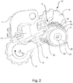
- the derailleur 10 shown better in fig. 2 , comprises a fixed body 11, mounted on the bicycle 1, close to the cogset 5, and a mobile body 12, mounted in a moveable manner on the fixed body 11 by means of an articulated quadrilateral linkage (per se conventional), two connecting rods 13 of which are partially visible in fig. 2 .
- the derailleur 10 further comprises a chain guide 15, which is mounted in an angularly moveable manner on the mobile body 12 about an axis X, parallel to the axis P of the cogset 5, and comprises two coplanar idle wheels 16 and 17, engaged with the chain 3.
- the idle wheel 16 is coaxial to the axis X and therefore does not change its position with respect to the mobile body 12, whereas the idle wheel 17 is arranged at an opposite end of the chain guide 15 and changes its position as a function of the angular movements of the chain guide 15 with respect to the mobile body 12.
- the two idle wheels 16 and 17 move together in the direction of the axis X, as a function of the movements of the mobile body 12 with respect to the fixed body 11, so as to take the chain 3 on different sprockets of the cogset 5 and thus obtain different gear ratios.
- the mobile body 12 comprises a load-bearing body 21, having a substantially annular shape around the axis X, closed at the two ends thereof along the axis X by a first closing body 22 and by a second closing body 23.
- the load-bearing body 21 is the part of mobile body 12 to which the connecting rods 13 are fixed.
- the two first and second closing bodies 22 and 23 are mounted in a fixed tight manner on the load-bearing body 21.
- the first closing body 22 is provided with threaded holes 24 in which screws 25 are screwed, inserted in eyelets 26 of the load-bearing body 21;
- the second closing body 23, on the other hand, is screwed directly to the load-bearing body 21, by means of corresponding threadings.
- a dividing body 30 is further mounted in the mobile body 12, said dividing body 30 being coaxial to the axis X, mechanically constrained to the load-bearing body 21 in the mobile body 12 by means of a helical coupling, with an internal helix 31 formed in the load-bearing body 21 and an external helix 32 formed on the dividing body 30. Thanks to this helical coupling, each rotation of the dividing body 30 about the axis X is accompanied by a translation of the dividing body 30 along the axis X itself, and vice-versa.
- the mobile body 12 also comprises a trailing body 40, which comprises two portions fixedly connected to each other, coaxial along the axis X: an inner portion 41, enclosed between the load-bearing body 21 and the first closing body 22 and mounted in a rotary manner about the axis X, and an outer portion 42, projecting from the first closing body 22 through an axial opening 43, and mounted fixedly connected to the chain guide 15 by means of a screw 44.
- a bush 45 is arranged between the trailing body 40 and the load-bearing body 21, to ensure that there is a seal and the possibility of rotation between them.
- the derailleur 10 comprises an elastic system between the chain guide 15 and the mobile body 12; this elastic system is formed from a spring 50, mounted on the first closing body 22 and fastening at an end 51 thereof to the first closing body 22 and at the other end 52 to the trailing body 40.
- the action of the spring 50 is in the sense of angularly pushing the trailing body 40 and with it the chain guide 15 in the direction that corresponds to a tensioning of the chain 3, indicated with TC in fig. 2 .
- the dividing body 30 comprises a male portion 33 and a female portion 34, coaxial along the axis X and fixedly connected to each other.
- the male portion 33 is slidably inserted in a tight manner in a cylindrical cavity 46 formed in the inner portion 41 of the trailing body 40; between the male portion 33 and the cylindrical cavity 46 a first variable volume chamber 35 is defined.
- a cylindrical cavity 36 is formed that received - in a sliding, rotatable and tight manner - a male portion 27 of the second closing body 23; between the male portion 27 and the cylindrical cavity 36 a second variable volume chamber 37 is defined.
- the chambers 35 and 37 change their volume as a consequence of the axial movement of the dividing body 30 along the axis X: when the dividing body 30 moves towards the first closing body 22, the first chamber 35 decreases in volume whereas the second chamber 37 increases in volume; vice-versa, when the dividing body 30 moves towards the second closing body 23, the first chamber 35 increases in volume whereas the second chamber 37 decreases in volume.
- the chambers 35 and 37 are filled with damping fluid (not highlighted in the figures), for example oil.
- damping fluid not highlighted in the figures
- the second closing body 23 is provided with a screw cap 55, for filling the cavities 35 and 37 with the damping fluid.
- the dividing body 30 is mechanically constrained to the chain guide 15 so as to move together with it in the angular direction about the axis X.
- the dividing body 30 is mechanically constrained to the trailing body 40, which - as stated - is fixedly connected to the chain guide 15 by the screw 44, by means of pins 47 extending parallel to the axis X (three pins in the example illustrated in the figures, arranged 120° apart about the axis X); the pins 47 are inserted free to slide in the longitudinal direction in holes 48 formed in the female portion 34 of the dividing body 30 and holes 49 formed in the inner portion 41 of the trailing body 40.
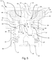
- the derailleur 10 further comprises a controlled fluid passage system 60 between the two variable volume chambers 35 and 37, to allow the controlled overflow of damping fluid between the two chambers 35 and 37 when they undergo changes in volume.
- the fluid passage system 60 is provided in the dividing body 30, but it is not highlighted in fig. 3 .
- the fluid passage system 60 is structured so as to be adapted for allowing fluid to pass in a first direction A through a calibrated nozzle, and for allowing fluid to pass in a second direction B opposite the first through a port of much greater size with respect to the nozzle;
- the first direction A of passage of the fluid is from the first chamber 35 to the second chamber 37, and thus corresponds to a movement of the dividing body 30 towards the first closing body 22
- the second direction B is from the second chamber 37 to the first chamber 35, and thus corresponds to a movement of the dividing body 30 towards the second closing body 23.
- the fluid passage system 60 comprises a central channel 61 that passes axially through the dividing body 30; in the central channel 61 a calibrated nozzle 62 is housed, namely a narrow passage of accurately defined size as a function of the damping that is wished to be obtained when the dividing body 30 moves towards the first closing body 22.
- the fluid passage system 60 further comprises a plurality of peripheral channels 63, which as a whole form a passage port of much larger size than that of the calibrated nozzle 62.
- the peripheral channels 63 are regulated by respective mobile shutters 64 positioned so as to close the passage port when there is a push of fluid in the first direction A and so as to leave the passage port open when there is a push of fluid in the second direction B.
- each peripheral channel 63 comprises a main hole 65 and an auxiliary hole 66, which have a circular section and are beside one another, oriented in the direction of the axis X.
- the main hole 65 is a through hole, i.e. it completely passes through the dividing body 30, while towards the second chamber 37 it has a throttling 67.
- the auxiliary hole 66 is blind, i.e. it is open towards the first chamber 35 and not towards the second chamber 37, and communicates with the main hole 65 which it is next to.
- the mobile shutter 64 is formed from a ball, inserted in the main hole 65 and held therein on one side by the throttling 67, and on the other side by a thrust wheel 68; this thrust wheel 68 (one for all of the peripheral channels 63) is mounted centrally in the dividing body 30, held in position by the calibrated nozzle 62, for this purpose provided with a shoulder 69.
- the volume of the first chamber 35 tends to reduce whereas the volume of the second chamber 37 tends to increase.
- the chain guide 15 is thus moved angularly about the axis X in direction TC, and the same angular movement is transmitted to the trailing body 40 and to the dividing body 30. Due to this rotation, the dividing body 30 moves axially along the axis X, towards the second closing body 23 (i.e. downwards in figs. 3 to 7 ). This situation corresponds to what is illustrated in figs. 5 and 7 .
- the fluid passage system 60 comprises a directional valve 162 housed in the central channel 61, i.e. a valve available on the market inside which the nozzle and the port are formed: in the first direction A, the flow of the fluid is braked, in proportion to the speed, whereas it is free in the direction B.
- the operation remains substantially the same as just described with reference to the first embodiment.
Landscapes
- Engineering & Computer Science (AREA)
- Mechanical Engineering (AREA)
- General Engineering & Computer Science (AREA)
- Chemical & Material Sciences (AREA)
- Combustion & Propulsion (AREA)
- Transportation (AREA)
- Devices For Conveying Motion By Means Of Endless Flexible Members (AREA)
- Fluid-Damping Devices (AREA)
- Platform Screen Doors And Railroad Systems (AREA)
- Sawing (AREA)
Applications Claiming Priority (1)
| Application Number | Priority Date | Filing Date | Title |
|---|---|---|---|
| ITUA2016A004291A ITUA20164291A1 (it) | 2016-06-10 | 2016-06-10 | Deragliatore con smorzatore del guidacatena |
Publications (2)
| Publication Number | Publication Date |
|---|---|
| EP3258134A1 EP3258134A1 (en) | 2017-12-20 |
| EP3258134B1 true EP3258134B1 (en) | 2019-05-08 |
Family
ID=57113625
Family Applications (1)
| Application Number | Title | Priority Date | Filing Date |
|---|---|---|---|
| EP17174835.3A Active EP3258134B1 (en) | 2016-06-10 | 2017-06-07 | Derailleur with damper of the chain guide |
Country Status (6)
| Country | Link |
|---|---|
| US (1) | US10137962B2 (https=) |
| EP (1) | EP3258134B1 (https=) |
| JP (1) | JP6840034B2 (https=) |
| CN (1) | CN107489748B (https=) |
| IT (1) | ITUA20164291A1 (https=) |
| TW (1) | TWI730116B (https=) |
Families Citing this family (7)
| Publication number | Priority date | Publication date | Assignee | Title |
|---|---|---|---|---|
| CN106741556B (zh) * | 2017-03-24 | 2023-04-18 | 速瑞达自行车零件(佛山)有限公司 | 一种具有附加旋转阻力功能的后拨链器及阻力施加方法 |
| US11560199B2 (en) * | 2018-12-12 | 2023-01-24 | Brandon Rodgers | Gearshifting system comprising a linear actuator |
| US11110993B2 (en) * | 2017-09-13 | 2021-09-07 | Brandon Rodgers | Damping device adapted for integration within a gearshifting system |
| TWI650270B (zh) * | 2017-12-29 | 2019-02-11 | 日馳企業股份有限公司 | 自行車撥鏈裝置 |
| US11814138B1 (en) * | 2022-06-28 | 2023-11-14 | Ad-Ii Engineering Inc. | Rear derailleur |
| CN115571259B (zh) * | 2022-10-20 | 2025-08-01 | 珠海蓝图运动科技股份有限公司 | 一种具有阻尼功能的后拨链器和自行车 |
| CN119568333B (zh) * | 2024-12-17 | 2025-12-09 | 珠海蓝图运动科技股份有限公司 | 液压阻尼器及后拨链器 |
Family Cites Families (17)
| Publication number | Priority date | Publication date | Assignee | Title |
|---|---|---|---|---|
| JPH02169383A (ja) * | 1988-12-22 | 1990-06-29 | Shimano Ind Co Ltd | 自転車用リヤディレーラー |
| US6042495A (en) * | 1997-12-24 | 2000-03-28 | Patterson; Richard A. | Hydraulically-operated bicycle shifting and braking systems |
| US6135904A (en) * | 1998-10-28 | 2000-10-24 | Guthrie; Ryan G. | Bicycle derailleur chain damper |
| US7032475B2 (en) * | 2001-06-07 | 2006-04-25 | Shimano Inc. | Hydraulic gear shift mechanism |
| ITMO20040107A1 (it) * | 2004-05-06 | 2004-08-06 | L A M S R L | Cambio per bicicletta |
| US20070219029A1 (en) | 2006-03-15 | 2007-09-20 | Maverick American Llc | Fluid dampening chain tensioning device |
| US8870692B2 (en) * | 2010-09-30 | 2014-10-28 | Shimano, Inc. | Bicycle derailleur with rotation resistance |
| US8900078B2 (en) * | 2011-10-05 | 2014-12-02 | Shimano Inc. | Bicycle derailleur |
| US9475547B2 (en) * | 2012-02-06 | 2016-10-25 | Brian Jordan | Derailleur with damping assembly |
| US9187149B2 (en) * | 2012-04-26 | 2015-11-17 | Shimano, Inc. | Bicycle derailleur with rotation resistance and resistance control |
| US8870693B2 (en) * | 2012-05-21 | 2014-10-28 | Shimano, Inc. | Bicycle derailleur with rotation resistance and tactile feedback |
| US8882618B2 (en) * | 2013-01-29 | 2014-11-11 | Shimano Inc. | Rear derailleur |
| US9228643B2 (en) * | 2013-09-12 | 2016-01-05 | Shimano Inc. | Chain tensioning device |
| US9377089B2 (en) * | 2013-09-12 | 2016-06-28 | Shimano Inc. | Chain tensioning device |
| DE102014225036A1 (de) * | 2013-12-23 | 2015-06-25 | Sram Deutschland Gmbh | Fahrradderailleur mit Reibungsdämpfung |
| US9751590B2 (en) * | 2014-08-15 | 2017-09-05 | Sram, Llc | Bicycle rear derailleur with a damper assembly |
| US9669900B2 (en) * | 2015-04-14 | 2017-06-06 | Shimano Inc. | Chain tensioning device |
-
2016
- 2016-06-10 IT ITUA2016A004291A patent/ITUA20164291A1/it unknown
-
2017
- 2017-06-01 JP JP2017108876A patent/JP6840034B2/ja active Active
- 2017-06-07 EP EP17174835.3A patent/EP3258134B1/en active Active
- 2017-06-08 TW TW106119022A patent/TWI730116B/zh active
- 2017-06-08 US US15/617,783 patent/US10137962B2/en active Active
- 2017-06-09 CN CN201710431285.8A patent/CN107489748B/zh active Active
Non-Patent Citations (1)
| Title |
|---|
| None * |
Also Published As
| Publication number | Publication date |
|---|---|
| TWI730116B (zh) | 2021-06-11 |
| US10137962B2 (en) | 2018-11-27 |
| US20170355423A1 (en) | 2017-12-14 |
| EP3258134A1 (en) | 2017-12-20 |
| ITUA20164291A1 (it) | 2017-12-10 |
| JP2018030566A (ja) | 2018-03-01 |
| CN107489748B (zh) | 2020-03-31 |
| JP6840034B2 (ja) | 2021-03-10 |
| TW201808720A (zh) | 2018-03-16 |
| CN107489748A (zh) | 2017-12-19 |
Similar Documents
| Publication | Publication Date | Title |
|---|---|---|
| EP3258134B1 (en) | Derailleur with damper of the chain guide | |
| US11649875B2 (en) | Fluid damper for a bicycle component | |
| US4836046A (en) | Automatic bicycle transmission | |
| KR910008159B1 (ko) | 감쇄력이 조정 가능한 유압 완충기 | |
| US10435111B2 (en) | Fluid damper for a bicycle component | |
| US3995508A (en) | Automatic bicycle transmission | |
| EP2388493B1 (de) | Dämpfer | |
| US20060091345A1 (en) | Actuator apparatus for controlling a valve mechanism of a suspension system | |
| US8499906B2 (en) | Bicycle suspension having stroke and damper adjustment | |
| CA2284435C (en) | Damper valve for hydraulic power steering device | |
| JP2018030566A5 (https=) | ||
| US10160515B2 (en) | Device for actuating the front derailleur of a bicycle | |
| DE102015210260A1 (de) | Fahrrad-Sattelstützenbaueinheit | |
| JP7055029B2 (ja) | 自転車のディレイラの制御ケーブルを作動させるメカニカル作動装置 | |
| ITUA20164005A1 (it) | Dispositivo di azionamento del cavo di comando di un cambio di una bicicletta | |
| DE3838359C2 (https=) | ||
| DE69200958T2 (de) | Vorderer umwerfer fuer eine fahrradkettenschaltung. | |
| IT201700015324A1 (it) | Deragliatore anteriore per bicicletta | |
| RU2387568C1 (ru) | Велосипед с автоматическим переключением передач | |
| DE19543704A1 (de) | Einrichtung zur automatischen Betätigung von Fahrrad-Mehrgangschaltungen | |
| ITMI20100214A1 (it) | Cambio di velocita' ad ingranaggi scorrevoli, particolarmente per velocipedi. |
Legal Events
| Date | Code | Title | Description |
|---|---|---|---|
| PUAI | Public reference made under article 153(3) epc to a published international application that has entered the european phase |
Free format text: ORIGINAL CODE: 0009012 |
|
| STAA | Information on the status of an ep patent application or granted ep patent |
Free format text: STATUS: THE APPLICATION HAS BEEN PUBLISHED |
|
| AK | Designated contracting states |
Kind code of ref document: A1 Designated state(s): AL AT BE BG CH CY CZ DE DK EE ES FI FR GB GR HR HU IE IS IT LI LT LU LV MC MK MT NL NO PL PT RO RS SE SI SK SM TR |
|
| AX | Request for extension of the european patent |
Extension state: BA ME |
|
| STAA | Information on the status of an ep patent application or granted ep patent |
Free format text: STATUS: REQUEST FOR EXAMINATION WAS MADE |
|
| 17P | Request for examination filed |
Effective date: 20180620 |
|
| RBV | Designated contracting states (corrected) |
Designated state(s): AL AT BE BG CH CY CZ DE DK EE ES FI FR GB GR HR HU IE IS IT LI LT LU LV MC MK MT NL NO PL PT RO RS SE SI SK SM TR |
|
| GRAP | Despatch of communication of intention to grant a patent |
Free format text: ORIGINAL CODE: EPIDOSNIGR1 |
|
| STAA | Information on the status of an ep patent application or granted ep patent |
Free format text: STATUS: GRANT OF PATENT IS INTENDED |
|
| RIC1 | Information provided on ipc code assigned before grant |
Ipc: B62M 9/1244 20100101ALI20181025BHEP Ipc: F16H 7/12 20060101AFI20181025BHEP Ipc: B62M 9/1248 20100101ALI20181025BHEP Ipc: B62M 9/122 20100101ALI20181025BHEP |
|
| INTG | Intention to grant announced |
Effective date: 20181127 |
|
| GRAS | Grant fee paid |
Free format text: ORIGINAL CODE: EPIDOSNIGR3 |
|
| GRAA | (expected) grant |
Free format text: ORIGINAL CODE: 0009210 |
|
| STAA | Information on the status of an ep patent application or granted ep patent |
Free format text: STATUS: THE PATENT HAS BEEN GRANTED |
|
| AK | Designated contracting states |
Kind code of ref document: B1 Designated state(s): AL AT BE BG CH CY CZ DE DK EE ES FI FR GB GR HR HU IE IS IT LI LT LU LV MC MK MT NL NO PL PT RO RS SE SI SK SM TR |
|
| REG | Reference to a national code |
Ref country code: GB Ref legal event code: FG4D |
|
| REG | Reference to a national code |
Ref country code: CH Ref legal event code: EP Ref country code: AT Ref legal event code: REF Ref document number: 1130632 Country of ref document: AT Kind code of ref document: T Effective date: 20190515 |
|
| REG | Reference to a national code |
Ref country code: DE Ref legal event code: R096 Ref document number: 602017003787 Country of ref document: DE Ref country code: IE Ref legal event code: FG4D |
|
| REG | Reference to a national code |
Ref country code: NL Ref legal event code: MP Effective date: 20190508 |
|
| REG | Reference to a national code |
Ref country code: LT Ref legal event code: MG4D |
|
| PG25 | Lapsed in a contracting state [announced via postgrant information from national office to epo] |
Ref country code: AL Free format text: LAPSE BECAUSE OF FAILURE TO SUBMIT A TRANSLATION OF THE DESCRIPTION OR TO PAY THE FEE WITHIN THE PRESCRIBED TIME-LIMIT Effective date: 20190508 Ref country code: PT Free format text: LAPSE BECAUSE OF FAILURE TO SUBMIT A TRANSLATION OF THE DESCRIPTION OR TO PAY THE FEE WITHIN THE PRESCRIBED TIME-LIMIT Effective date: 20190908 Ref country code: SE Free format text: LAPSE BECAUSE OF FAILURE TO SUBMIT A TRANSLATION OF THE DESCRIPTION OR TO PAY THE FEE WITHIN THE PRESCRIBED TIME-LIMIT Effective date: 20190508 Ref country code: FI Free format text: LAPSE BECAUSE OF FAILURE TO SUBMIT A TRANSLATION OF THE DESCRIPTION OR TO PAY THE FEE WITHIN THE PRESCRIBED TIME-LIMIT Effective date: 20190508 Ref country code: NO Free format text: LAPSE BECAUSE OF FAILURE TO SUBMIT A TRANSLATION OF THE DESCRIPTION OR TO PAY THE FEE WITHIN THE PRESCRIBED TIME-LIMIT Effective date: 20190808 Ref country code: HR Free format text: LAPSE BECAUSE OF FAILURE TO SUBMIT A TRANSLATION OF THE DESCRIPTION OR TO PAY THE FEE WITHIN THE PRESCRIBED TIME-LIMIT Effective date: 20190508 Ref country code: NL Free format text: LAPSE BECAUSE OF FAILURE TO SUBMIT A TRANSLATION OF THE DESCRIPTION OR TO PAY THE FEE WITHIN THE PRESCRIBED TIME-LIMIT Effective date: 20190508 Ref country code: LT Free format text: LAPSE BECAUSE OF FAILURE TO SUBMIT A TRANSLATION OF THE DESCRIPTION OR TO PAY THE FEE WITHIN THE PRESCRIBED TIME-LIMIT Effective date: 20190508 Ref country code: ES Free format text: LAPSE BECAUSE OF FAILURE TO SUBMIT A TRANSLATION OF THE DESCRIPTION OR TO PAY THE FEE WITHIN THE PRESCRIBED TIME-LIMIT Effective date: 20190508 |
|
| PG25 | Lapsed in a contracting state [announced via postgrant information from national office to epo] |
Ref country code: RS Free format text: LAPSE BECAUSE OF FAILURE TO SUBMIT A TRANSLATION OF THE DESCRIPTION OR TO PAY THE FEE WITHIN THE PRESCRIBED TIME-LIMIT Effective date: 20190508 Ref country code: BG Free format text: LAPSE BECAUSE OF FAILURE TO SUBMIT A TRANSLATION OF THE DESCRIPTION OR TO PAY THE FEE WITHIN THE PRESCRIBED TIME-LIMIT Effective date: 20190808 Ref country code: LV Free format text: LAPSE BECAUSE OF FAILURE TO SUBMIT A TRANSLATION OF THE DESCRIPTION OR TO PAY THE FEE WITHIN THE PRESCRIBED TIME-LIMIT Effective date: 20190508 Ref country code: GR Free format text: LAPSE BECAUSE OF FAILURE TO SUBMIT A TRANSLATION OF THE DESCRIPTION OR TO PAY THE FEE WITHIN THE PRESCRIBED TIME-LIMIT Effective date: 20190809 |
|
| REG | Reference to a national code |
Ref country code: AT Ref legal event code: MK05 Ref document number: 1130632 Country of ref document: AT Kind code of ref document: T Effective date: 20190508 |
|
| PG25 | Lapsed in a contracting state [announced via postgrant information from national office to epo] |
Ref country code: DK Free format text: LAPSE BECAUSE OF FAILURE TO SUBMIT A TRANSLATION OF THE DESCRIPTION OR TO PAY THE FEE WITHIN THE PRESCRIBED TIME-LIMIT Effective date: 20190508 Ref country code: AT Free format text: LAPSE BECAUSE OF FAILURE TO SUBMIT A TRANSLATION OF THE DESCRIPTION OR TO PAY THE FEE WITHIN THE PRESCRIBED TIME-LIMIT Effective date: 20190508 Ref country code: EE Free format text: LAPSE BECAUSE OF FAILURE TO SUBMIT A TRANSLATION OF THE DESCRIPTION OR TO PAY THE FEE WITHIN THE PRESCRIBED TIME-LIMIT Effective date: 20190508 Ref country code: SK Free format text: LAPSE BECAUSE OF FAILURE TO SUBMIT A TRANSLATION OF THE DESCRIPTION OR TO PAY THE FEE WITHIN THE PRESCRIBED TIME-LIMIT Effective date: 20190508 Ref country code: RO Free format text: LAPSE BECAUSE OF FAILURE TO SUBMIT A TRANSLATION OF THE DESCRIPTION OR TO PAY THE FEE WITHIN THE PRESCRIBED TIME-LIMIT Effective date: 20190508 Ref country code: CZ Free format text: LAPSE BECAUSE OF FAILURE TO SUBMIT A TRANSLATION OF THE DESCRIPTION OR TO PAY THE FEE WITHIN THE PRESCRIBED TIME-LIMIT Effective date: 20190508 |
|
| REG | Reference to a national code |
Ref country code: DE Ref legal event code: R097 Ref document number: 602017003787 Country of ref document: DE |
|
| PG25 | Lapsed in a contracting state [announced via postgrant information from national office to epo] |
Ref country code: MC Free format text: LAPSE BECAUSE OF FAILURE TO SUBMIT A TRANSLATION OF THE DESCRIPTION OR TO PAY THE FEE WITHIN THE PRESCRIBED TIME-LIMIT Effective date: 20190508 Ref country code: SM Free format text: LAPSE BECAUSE OF FAILURE TO SUBMIT A TRANSLATION OF THE DESCRIPTION OR TO PAY THE FEE WITHIN THE PRESCRIBED TIME-LIMIT Effective date: 20190508 |
|
| PLBE | No opposition filed within time limit |
Free format text: ORIGINAL CODE: 0009261 |
|
| STAA | Information on the status of an ep patent application or granted ep patent |
Free format text: STATUS: NO OPPOSITION FILED WITHIN TIME LIMIT |
|
| REG | Reference to a national code |
Ref country code: BE Ref legal event code: MM Effective date: 20190630 |
|
| PG25 | Lapsed in a contracting state [announced via postgrant information from national office to epo] |
Ref country code: TR Free format text: LAPSE BECAUSE OF FAILURE TO SUBMIT A TRANSLATION OF THE DESCRIPTION OR TO PAY THE FEE WITHIN THE PRESCRIBED TIME-LIMIT Effective date: 20190508 |
|
| 26N | No opposition filed |
Effective date: 20200211 |
|
| PG25 | Lapsed in a contracting state [announced via postgrant information from national office to epo] |
Ref country code: PL Free format text: LAPSE BECAUSE OF FAILURE TO SUBMIT A TRANSLATION OF THE DESCRIPTION OR TO PAY THE FEE WITHIN THE PRESCRIBED TIME-LIMIT Effective date: 20190508 Ref country code: IE Free format text: LAPSE BECAUSE OF NON-PAYMENT OF DUE FEES Effective date: 20190607 |
|
| PG25 | Lapsed in a contracting state [announced via postgrant information from national office to epo] |
Ref country code: SI Free format text: LAPSE BECAUSE OF FAILURE TO SUBMIT A TRANSLATION OF THE DESCRIPTION OR TO PAY THE FEE WITHIN THE PRESCRIBED TIME-LIMIT Effective date: 20190508 Ref country code: LU Free format text: LAPSE BECAUSE OF NON-PAYMENT OF DUE FEES Effective date: 20190607 Ref country code: BE Free format text: LAPSE BECAUSE OF NON-PAYMENT OF DUE FEES Effective date: 20190630 |
|
| REG | Reference to a national code |
Ref country code: CH Ref legal event code: PL |
|
| PG25 | Lapsed in a contracting state [announced via postgrant information from national office to epo] |
Ref country code: CH Free format text: LAPSE BECAUSE OF NON-PAYMENT OF DUE FEES Effective date: 20200630 Ref country code: LI Free format text: LAPSE BECAUSE OF NON-PAYMENT OF DUE FEES Effective date: 20200630 |
|
| PG25 | Lapsed in a contracting state [announced via postgrant information from national office to epo] |
Ref country code: CY Free format text: LAPSE BECAUSE OF FAILURE TO SUBMIT A TRANSLATION OF THE DESCRIPTION OR TO PAY THE FEE WITHIN THE PRESCRIBED TIME-LIMIT Effective date: 20190508 |
|
| PG25 | Lapsed in a contracting state [announced via postgrant information from national office to epo] |
Ref country code: IS Free format text: LAPSE BECAUSE OF FAILURE TO SUBMIT A TRANSLATION OF THE DESCRIPTION OR TO PAY THE FEE WITHIN THE PRESCRIBED TIME-LIMIT Effective date: 20190908 |
|
| PG25 | Lapsed in a contracting state [announced via postgrant information from national office to epo] |
Ref country code: HU Free format text: LAPSE BECAUSE OF FAILURE TO SUBMIT A TRANSLATION OF THE DESCRIPTION OR TO PAY THE FEE WITHIN THE PRESCRIBED TIME-LIMIT; INVALID AB INITIO Effective date: 20170607 Ref country code: MT Free format text: LAPSE BECAUSE OF FAILURE TO SUBMIT A TRANSLATION OF THE DESCRIPTION OR TO PAY THE FEE WITHIN THE PRESCRIBED TIME-LIMIT Effective date: 20190508 |
|
| GBPC | Gb: european patent ceased through non-payment of renewal fee |
Effective date: 20210607 |
|
| PG25 | Lapsed in a contracting state [announced via postgrant information from national office to epo] |
Ref country code: GB Free format text: LAPSE BECAUSE OF NON-PAYMENT OF DUE FEES Effective date: 20210607 |
|
| PG25 | Lapsed in a contracting state [announced via postgrant information from national office to epo] |
Ref country code: MK Free format text: LAPSE BECAUSE OF FAILURE TO SUBMIT A TRANSLATION OF THE DESCRIPTION OR TO PAY THE FEE WITHIN THE PRESCRIBED TIME-LIMIT Effective date: 20190508 |
|
| P01 | Opt-out of the competence of the unified patent court (upc) registered |
Effective date: 20230518 |
|
| PGFP | Annual fee paid to national office [announced via postgrant information from national office to epo] |
Ref country code: DE Payment date: 20250627 Year of fee payment: 9 |
|
| PGFP | Annual fee paid to national office [announced via postgrant information from national office to epo] |
Ref country code: FR Payment date: 20250625 Year of fee payment: 9 |
|
| PGFP | Annual fee paid to national office [announced via postgrant information from national office to epo] |
Ref country code: IT Payment date: 20250619 Year of fee payment: 9 |