EP3256229B1 - Installation de distillation à étages multiples, procédé permettant de faire fonctionner une installation de ce type - Google Patents
Installation de distillation à étages multiples, procédé permettant de faire fonctionner une installation de ce type Download PDFInfo
- Publication number
- EP3256229B1 EP3256229B1 EP16704179.7A EP16704179A EP3256229B1 EP 3256229 B1 EP3256229 B1 EP 3256229B1 EP 16704179 A EP16704179 A EP 16704179A EP 3256229 B1 EP3256229 B1 EP 3256229B1
- Authority
- EP
- European Patent Office
- Prior art keywords
- evaporator
- liquid
- condenser
- pressure
- circuit
- Prior art date
- Legal status (The legal status is an assumption and is not a legal conclusion. Google has not performed a legal analysis and makes no representation as to the accuracy of the status listed.)
- Active
Links
- 238000004821 distillation Methods 0.000 title claims description 52
- 238000000034 method Methods 0.000 title claims description 46
- 239000007788 liquid Substances 0.000 claims description 122
- 239000003990 capacitor Substances 0.000 claims description 28
- 239000007789 gas Substances 0.000 claims description 20
- 239000007921 spray Substances 0.000 claims description 18
- 238000001816 cooling Methods 0.000 claims description 7
- 238000012544 monitoring process Methods 0.000 claims description 4
- 238000005507 spraying Methods 0.000 claims description 4
- 238000001704 evaporation Methods 0.000 claims description 2
- 230000008020 evaporation Effects 0.000 claims description 2
- 238000007599 discharging Methods 0.000 description 9
- 239000012530 fluid Substances 0.000 description 5
- 238000009833 condensation Methods 0.000 description 4
- 230000005494 condensation Effects 0.000 description 4
- 238000005259 measurement Methods 0.000 description 2
- 238000005381 potential energy Methods 0.000 description 2
- 230000001105 regulatory effect Effects 0.000 description 2
- 238000000926 separation method Methods 0.000 description 2
- LFQSCWFLJHTTHZ-UHFFFAOYSA-N Ethanol Chemical compound CCO LFQSCWFLJHTTHZ-UHFFFAOYSA-N 0.000 description 1
- 238000009835 boiling Methods 0.000 description 1
- 150000003839 salts Chemical class 0.000 description 1
- XLYOFNOQVPJJNP-UHFFFAOYSA-N water Substances O XLYOFNOQVPJJNP-UHFFFAOYSA-N 0.000 description 1
Images


Classifications
-
- B—PERFORMING OPERATIONS; TRANSPORTING
- B01—PHYSICAL OR CHEMICAL PROCESSES OR APPARATUS IN GENERAL
- B01D—SEPARATION
- B01D1/00—Evaporating
- B01D1/26—Multiple-effect evaporating
-
- B—PERFORMING OPERATIONS; TRANSPORTING
- B01—PHYSICAL OR CHEMICAL PROCESSES OR APPARATUS IN GENERAL
- B01D—SEPARATION
- B01D1/00—Evaporating
-
- B—PERFORMING OPERATIONS; TRANSPORTING
- B01—PHYSICAL OR CHEMICAL PROCESSES OR APPARATUS IN GENERAL
- B01D—SEPARATION
- B01D1/00—Evaporating
- B01D1/0082—Regulation; Control
-
- B—PERFORMING OPERATIONS; TRANSPORTING
- B01—PHYSICAL OR CHEMICAL PROCESSES OR APPARATUS IN GENERAL
- B01D—SEPARATION
- B01D5/00—Condensation of vapours; Recovering volatile solvents by condensation
-
- B—PERFORMING OPERATIONS; TRANSPORTING
- B01—PHYSICAL OR CHEMICAL PROCESSES OR APPARATUS IN GENERAL
- B01D—SEPARATION
- B01D5/00—Condensation of vapours; Recovering volatile solvents by condensation
- B01D5/0033—Other features
- B01D5/0036—Multiple-effect condensation; Fractional condensation
-
- B—PERFORMING OPERATIONS; TRANSPORTING
- B01—PHYSICAL OR CHEMICAL PROCESSES OR APPARATUS IN GENERAL
- B01D—SEPARATION
- B01D5/00—Condensation of vapours; Recovering volatile solvents by condensation
- B01D5/0033—Other features
- B01D5/0051—Regulation processes; Control systems, e.g. valves
-
- B—PERFORMING OPERATIONS; TRANSPORTING
- B01—PHYSICAL OR CHEMICAL PROCESSES OR APPARATUS IN GENERAL
- B01D—SEPARATION
- B01D5/00—Condensation of vapours; Recovering volatile solvents by condensation
- B01D5/0057—Condensation of vapours; Recovering volatile solvents by condensation in combination with other processes
- B01D5/006—Condensation of vapours; Recovering volatile solvents by condensation in combination with other processes with evaporation or distillation
-
- C—CHEMISTRY; METALLURGY
- C02—TREATMENT OF WATER, WASTE WATER, SEWAGE, OR SLUDGE
- C02F—TREATMENT OF WATER, WASTE WATER, SEWAGE, OR SLUDGE
- C02F1/00—Treatment of water, waste water, or sewage
-
- C—CHEMISTRY; METALLURGY
- C02—TREATMENT OF WATER, WASTE WATER, SEWAGE, OR SLUDGE
- C02F—TREATMENT OF WATER, WASTE WATER, SEWAGE, OR SLUDGE
- C02F1/00—Treatment of water, waste water, or sewage
- C02F1/02—Treatment of water, waste water, or sewage by heating
- C02F1/04—Treatment of water, waste water, or sewage by heating by distillation or evaporation
- C02F1/048—Purification of waste water by evaporation
-
- C—CHEMISTRY; METALLURGY
- C02—TREATMENT OF WATER, WASTE WATER, SEWAGE, OR SLUDGE
- C02F—TREATMENT OF WATER, WASTE WATER, SEWAGE, OR SLUDGE
- C02F2103/00—Nature of the water, waste water, sewage or sludge to be treated
- C02F2103/08—Seawater, e.g. for desalination
-
- C—CHEMISTRY; METALLURGY
- C02—TREATMENT OF WATER, WASTE WATER, SEWAGE, OR SLUDGE
- C02F—TREATMENT OF WATER, WASTE WATER, SEWAGE, OR SLUDGE
- C02F2201/00—Apparatus for treatment of water, waste water or sewage
- C02F2201/009—Apparatus with independent power supply, e.g. solar cells, windpower or fuel cells
-
- C—CHEMISTRY; METALLURGY
- C02—TREATMENT OF WATER, WASTE WATER, SEWAGE, OR SLUDGE
- C02F—TREATMENT OF WATER, WASTE WATER, SEWAGE, OR SLUDGE
- C02F2209/00—Controlling or monitoring parameters in water treatment
- C02F2209/42—Liquid level
-
- Y—GENERAL TAGGING OF NEW TECHNOLOGICAL DEVELOPMENTS; GENERAL TAGGING OF CROSS-SECTIONAL TECHNOLOGIES SPANNING OVER SEVERAL SECTIONS OF THE IPC; TECHNICAL SUBJECTS COVERED BY FORMER USPC CROSS-REFERENCE ART COLLECTIONS [XRACs] AND DIGESTS
- Y02—TECHNOLOGIES OR APPLICATIONS FOR MITIGATION OR ADAPTATION AGAINST CLIMATE CHANGE
- Y02A—TECHNOLOGIES FOR ADAPTATION TO CLIMATE CHANGE
- Y02A20/00—Water conservation; Efficient water supply; Efficient water use
- Y02A20/124—Water desalination
-
- Y—GENERAL TAGGING OF NEW TECHNOLOGICAL DEVELOPMENTS; GENERAL TAGGING OF CROSS-SECTIONAL TECHNOLOGIES SPANNING OVER SEVERAL SECTIONS OF THE IPC; TECHNICAL SUBJECTS COVERED BY FORMER USPC CROSS-REFERENCE ART COLLECTIONS [XRACs] AND DIGESTS
- Y02—TECHNOLOGIES OR APPLICATIONS FOR MITIGATION OR ADAPTATION AGAINST CLIMATE CHANGE
- Y02A—TECHNOLOGIES FOR ADAPTATION TO CLIMATE CHANGE
- Y02A20/00—Water conservation; Efficient water supply; Efficient water use
- Y02A20/20—Controlling water pollution; Waste water treatment
- Y02A20/208—Off-grid powered water treatment
- Y02A20/212—Solar-powered wastewater sewage treatment, e.g. spray evaporation
Definitions
- the invention relates to a multi-stage distillation plant, wherein in operation each stage operates at a higher pressure and temperature range than its subsequent stage, each stage comprising an evaporator and a condenser each having a pressure-resistant container with a top spray inlet for introducing and spraying added liquid, and with a lower outlet for discharging trapped liquid, as well as a vapor space between the spray inlet and the collected liquid, wherein the vapor space of each evaporator is pressure-connected to the vapor space of the condenser of the same stage via a pressure-resistant steam tube with such a large cross-section that in Operation, the pressure in the two vapor chambers of a stage can always compensate, and wherein the outlet of each evaporator with the spray inlet of the next evaporator and the outlet of the last evaporator with the spray inlet of the first evaporator, each with a pressure-resistant liquid is connected to an evaporator circuit, and wherein the outlet of each condenser is connected to the spray
- Distillation plants have been known for a long time. They serve, for example, the treatment of water or the separation of alcohol from other liquids and are used in many other systems.
- the liquid to be distilled is evaporated with the addition of heat in order to separate it from the residues, for example from salts or from other liquids with a higher boiling point.
- the steam is finally cooled in another chamber, whereby it condenses to the distillate.
- Object of the present invention is therefore to improve a multi-stage distillation unit of the type described above such that the power consumption during operation is reduced.
- Another object of the present invention is to describe a method which performs such a distillation and to set out a control for its operation.
- the distillation unit described above comprises a pressure-resistant steam line which is connected at a first end to one of the pressure-resistant liquid lines between two adjacent condensers or to the pressure-resistant liquid line between the last and the first evaporator.
- the second end of the pressure-resistant steam line is connected to a vapor space, which has a higher pressure during operation than the pressure in the pressure-resistant liquid line, for applying the liquid with a higher pressure and for conveying the liquid.
- the liquid in the liquid line is pressurized to a higher pressure, allowing it to evaporate in a higher temperature stage.
- the pressurized liquid can carry the liquid to a container placed at a higher potential without having to use electrical power. As a result, no pump is needed during continuous operation.
- pumps in the evaporator and condenser circuits are still installed, they are only necessary to start the process initially. After just a few minutes, the process runs independently, without pumps for the circulation of the Liquids must be operated in the circuits. Only a vacuum pump for the suction of non-condensable gases at the end of the condensation paths in the condensers must be temporarily put into operation, but only for a short time.
- the power consumption can be drastically reduced in the inventive distillation plant.
- only one pump is necessary in each of the circuits, which also reduces the investment costs of the distillation plant.
- the inventive method for operating a distillation process using a distillation apparatus is characterized by the following process steps: Monitoring the quantities of fluid in both circuits; Monitor the concentration of residues in the evaporator circuit; Discharging liquid with a high concentration of the residues at the outlet as soon as the liquid in the evaporator circuit has reached a predetermined maximum level and / or the concentration of the residues in the evaporator circuit has reached a predetermined maximum value; Discharging distillate from the condenser circuit at the distillate outlet as soon as the liquid in the condenser circuit has reached a predetermined maximum level; Inlet of liquid in the condenser circuit at the inlet, as soon as the liquid in the evaporator circuit has reached a predetermined minimum level and / or the concentration of the residues in the evaporator circuit has reached a predetermined maximum value.
- liquid is only discharged from the evaporator circuit when both the maximum and maximum levels are reached, and that is until the minimum level is reached. Then, by adding fresh liquid to the maximum level, the concentration is lowered. The level is then raised again up to the maximum level as soon as the minimum level or the maximum concentration is reached.
- a distillation plant which comprises a vacuum pump connected by a gas line to the end of each condensation path of each condenser.
- the method is characterized by the method steps: Determining the temperature differences in the vapor spaces of the evaporators and condensers of the same stage; Removal of non-condensable gases in the Steam space of a condenser through the gas line with the aid of the vacuum pump, as soon as the corresponding temperature difference has reached a predetermined maximum value until it has fallen below a predetermined minimum value. These steps are repeated until the process is stopped.
- the inventive controller for operating a method according to the invention comprises connections for sensors for reading in measurement data, a processor for evaluating the measurement data and connections for changing the settings of valves and pumps.
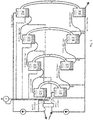
- Fig. 1 shows a multi-stage distillation unit 1 according to the prior art.
- the step S1 is also bordered by a dashed line, except for a part which is connected by a heat exchanger 14 to the step S2.
- Each stage S consists of an evaporator (or evaporator) E1, E2, E3, which respectively make up the left-hand chamber of each stage S1, S2, S3, and a condenser (or condenser) C1, C2, C3, respectively, the right-hand illustrated chamber the level S makes.
- the evaporators and condensers all have a steam space, wherein the steam chambers of the evaporators E1, E2, E3 and the capacitors C1, C2, C3 of the respective same stage S1, S2, S3 are connected to each other by a connecting steam space 6, wherein this connecting Steam space 6 is dimensioned so large that the pressure P within the steam rooms of this stage can compensate unhindered. Accordingly, the same pressure P1, P2, P3 prevails in both chambers of each stage S1, S2, S3. In each chamber, liquid 4 is brought upwardly from the chamber to a spray inlet 3 and sprayed there.
- the sprayed liquids 4a in the evaporators E1, E2, E3 have a slightly higher temperature than the sprayed liquids 4a of the capacitors C1, C2, C3 of the same stage.
- the temperatures of the evaporators E1, E2, E are correspondingly slightly above, the temperatures of the capacitors C1, C2, C3 slightly below the temperatures Ts1, Ts2, Ts3 of the saturation curve for the respective vapor pressure P1, P2, P3, which is known for the respective liquid.
- the first stage S1 thus operates at a temperature T1,1 in the evaporator E1, resp. with the temperature T1,2 in the condenser C1, by spraying the liquids 4a into the chambers at the indicated temperatures.
- the adjacent chamber of the condenser C1 is the evaporator E2, which forms the second stage S2 with the condenser C2.
- the lower regions of the chambers C1 and E2 are designed as heat exchangers 14. The same applies to the chambers C2 and E3, which are also connected to each other with a heat exchanger 14, so that the temperature T2,2 of the capacitor C2 and the temperature T3,1 of the evaporator E3 always keep the same temperatures.
- Temperature and pressure measuring devices 26, 27 in each vapor space 6 are used for process monitoring.
- a vacuum pump V at the end of each condensation path allows the suction of non-condensable gases in the system. This is important for the process to run efficiently.
- the individual stages are connected to one another only with heat exchangers, so that no exchange or flow of liquids or vapors between the various stages S can occur.
- the steps are only connected to one another via heat exchangers.
- the individual stages S work in different, adjacent temperature ranges, but each for themselves.
- Fig. 2 shows an embodiment of the invention.
- Fig. 3 is an investment according to Fig. 2 where examples are given of pressure and temperature values of the individual containers and pressure chambers are given, which can be adjusted according to the invention.
- Each stage Si comprises an evaporator Ei and a condenser Ci, each evaporator Ei and each condenser Ci comprising a pressure-resistant container 2 with an upper spray inlet 3 for introducing and spraying added liquid 4a in the container 2, as well as with a lower outlet 5, to Omission of liquid 4b caught in the container 2.
- each container 2 comprises a vapor space 6 between the spray inlet 3 and the collected liquid 4b, wherein the vapor space 6 of each evaporator Ei is pressure-connected to the vapor space 6 of the condenser Ci of the same stage Si via a pressure-resistant steam tube 7 with such a large cross-section that in Operation of the pressure Pi in the two steam chambers 6 a stage Si can always compensate.
- each evaporator Ei is connected to the spray inlet 3 of the next evaporator Ei + 1 and the outlet 5 of the last evaporator En is connected to the spray inlet 3 of the first evaporator E1, each with a pressure-resistant liquid line 8 to an evaporator circuit.
- the outlet 5 of each capacitor Ci is connected to the spray inlet 3 of the previous condenser Ci-1 and the outlet 5 of the first condenser C1 to the spray inlet 3 of the last condenser Cn with a pressure-resistant liquid line 9 to a condenser circuit.
- the arrangement of the container 2 can in particular also be changed so that the circuits of the evaporator and capacitors are arranged at the same level.
- the capacitor Cn and the evaporator E1 would be at the same or similar level, as would the condenser C1 and the evaporator En. This shortens the length of the connecting steam rooms 6.
- the specified Figures 2 and 3 have been presented for clarity and are to be understood as schematic representations.
- This support can be supplied either by pumps or by steam pressure.
- steam at a higher pressure is fed into a fluid line than the pressure in the target chamber, the fluid in the line is carried into the target chamber.
- steam can be taken from a steam room of the distillation unit 1.
- a steam chamber 25 can be set up, in which the liquid flowing through becomes partly steam. This steam is the hottest of the entire distillation unit 1 and also the one with the highest pressure. The pressure in this steam chamber 25 is even higher than the pressure in the evaporator E1.
- liquid 4 can be conveyed and pressurized, which must be brought under a little lower pressure. Examples are in Fig. 2 and 3 seen.
- the steam rooms 6 from stages S with lower pressures can convey corresponding liquids whose target containers 2 are under lower pressure than the steam chambers 6, of which the steam lines 10 have their pressure forth.
- the distillation unit 1 has a respective pump 11 in the liquid line 8 of the evaporator circuit and in the liquid line 9 of the condenser circuit, to reach the predetermined pressures of the liquids 4 at the beginning of the process. These must each run only a few minutes until the pressure and temperature conditions in all containers 2 have been ideally adjusted. The process then runs independently.
- the pumps 11 are preferably in the connecting lines 8, 9 between the containers C1 and Cn, respectively. arranged between the containers En and E1.
- the distillation unit 1 preferably has a heater 12 in the liquid line 8 of the evaporator circuit in front of the evaporator E1 and a cooling unit 13 in the liquid line of the condenser circuit before Capacitor Cn to achieve the predetermined temperatures in the evaporator E1 and in the capacitor Cn.
- This heater 12 and this cooling unit 13 are preferably at least partially configured together as a heat exchanger 14. Since the heat exchanger 14 but not the desired target temperatures of the next container Cn resp. E1 can reach, in the lines 8, 9 are still each a separate cooling unit 13 in the liquid line of the condenser circuit and a separate heater 12 in the liquid line 8 of the evaporator circuit necessary.
- the siphons 15 in the liquid lines 8 between the evaporators E1 and En have a central spout. It has been shown that there accumulate more residues, which can be easily removed in high concentration from the circulation.
- each capacitor Ci at the end of the distillation path via a connected to a vacuum pump 16 gas line 17. If necessary, the vacuum pump 16 is put into operation, but also only a short time is required, usually less than 5% of the operating time.
- the vacuum pump 16 can also be operated with steam. To feed them during operation, they must be connected to a pressure-resistant steam line 10. The vacuum pump 16 is thereby supplied with steam, which has a higher pressure P than the steam chambers 6, in which gases are to be sucked off.
- each evaporator Ei + 1 is arranged at such a lower level than the previous evaporator Ei, that during the execution of the process, the liquid 4 alone by pressure and level differences of each Evaporator egg in the following evaporator Ei + 1 flows, without the need for an electrically operated pump is necessary. Since each subsequent stage Si + 1 operates at a lower pressure than its previous stage S1, the subsequent stage Si + 1 can be arranged correspondingly higher, so that the liquid flows up due to its increased pressure.
- each capacitor Ci + 1 is arranged at a level situated in this way in comparison to its following capacitor Ci, that during the process execution the liquid from the capacitor Ci + 1 by pressure, level differences and / or by the conveying force of a steam line in the next capacitor Ci flows without the need for an electrically operated pump. Since in the condenser circuit the flow direction is directed counter to the direction of flow in the evaporator, the liquid flows from containers 2 with lower pressures to containers 2 with higher pressures. This can be partially assisted by placing the higher stage capacitors higher than the lower stage capacitors. For support, the liquid is additionally supplied by the supply of steam lines 10 with steam at a higher pressure. This avoids having to use pumps that consume power.
- the capacitors C1 and Cn are arranged leveled such that during the process execution, the liquid 4 flows from the condenser C1 by pressure and level differences through the liquid line 9 of the condenser circuit from the condenser C1 to the condenser Cn, without the need for an electrically operated pump is necessary , Since the pressure in C1 is much higher than in Cn, a great height can be overcome without the need for a pump.
- the evaporators En and E1 are preferably also leveled such that during the process execution, the liquid 4 flows from the evaporator En by pressure and level differences and by the conveying force of one or more steam lines 10 via the liquid line 8 of the evaporator circuit from the evaporator En to the evaporator E1 without the need for an electrically operated pump.
- both height must be overcome and pressure applied.
- This is preferably achieved in stages by introducing a plurality of steam lines 10 from different stages S into the liquid line 8.
- the various steam lines 10 can also all be introduced at the same point in the liquid line 8 but operated sequentially, so that always the most suitable steam line 10 is in operation.
- the steam lines 10 can optionally also be guided within the liquid line 8, 9.
- the inventive distillation unit 1 comprises an inlet 18 in the evaporator circuit, for supplying to be distilled liquid 4, and an outlet 19 from the evaporator circuit for discharging liquid 4 with a high concentration of residues, and a distillate outlet 20 from the condenser circuit for discharging the distillate 21 produced by the plant Fig. 2 shown.
- each steam line 10 and / or each gas line 17 comprises a valve 22 for regulating the flow rate.
- These valves 17 are preferably controllable and connected to a control device.
- At least the containers 2 of the first condenser C1 and the last evaporator E4 each comprise a level sensor 23 for determining the levels of the liquid 4b collected in the containers 2.
- the other containers 2 may also have such level sensors 23.
- the preferred distillation unit 1 in the evaporation circuit preferably in the region of the last evaporator En, has a sensor 24 for measuring the concentration of the residues.
- the sensors 23, 24 are also preferably controllable and connected to a control device, which is not shown.
- inventive method for operating a distillation process using a distillation unit 1 which comprises a feed 18 in the evaporator circuit for supplying liquid to be distilled 4, and an outlet 19 from the evaporator circuit, for discharging liquid 4 with a high concentration of the residues, as well as a distillate outlet 20 from the condenser circuit, for discharging the distillate 21 produced by the distillation plant.
- the following process steps are carried out in this process: Monitor the liquid level in the evaporator circuit and in the condenser circuit; Monitor the concentration of residues in the evaporator circuit; Discharging liquid with a high concentration of the residues at the outlet 19 as soon as the liquid level in the evaporator circuit has reached a predetermined maximum level and / or the concentration of the residues in the evaporator circuit has reached a predetermined maximum value; Discharging distillate from the condenser circuit at the distillate outlet 20 once the liquid level in the condenser circuit has reached a predetermined maximum level; Inlet of liquid 4 in the condenser circuit at the inlet 18 as soon as the liquid level in the evaporator circuit a predetermined minimum value and / or the concentration of the residues in the evaporator Circulation has reached a predetermined maximum value.
- the above steps are repeated until the process is stopped.
- the process is supplemented by the following process steps: Determining the temperature differences dTi in the steam chambers 6 of the container 2 of evaporator Ei and capacitor Ci the same stage Si; Removing non-condensable gases in the vapor space 6 of the capacitor Ci through the gas line 17 by means of the vacuum pump 16 as soon as the temperature difference dTi has reached a predetermined maximum value until dTi has reached a predetermined minimum value; Repeat these steps until the process is stopped.
- a controller according to the invention for operating a method according to the invention comprises connections for sensors for reading in measured data, a processor for evaluating the measured data and connections for changing the settings of valves 22 and pumps 11, 16.
- valves 22 are open as a rule. At the beginning of the process, it may be that some valves 22 are closed or throttled.
Landscapes
- Chemical & Material Sciences (AREA)
- Chemical Kinetics & Catalysis (AREA)
- Engineering & Computer Science (AREA)
- Life Sciences & Earth Sciences (AREA)
- Hydrology & Water Resources (AREA)
- Environmental & Geological Engineering (AREA)
- Water Supply & Treatment (AREA)
- Organic Chemistry (AREA)
- Automation & Control Theory (AREA)
- Vaporization, Distillation, Condensation, Sublimation, And Cold Traps (AREA)
Claims (15)
- Installation de distillation à plusieurs niveaux (1) avec des niveaux Si à i=1,....n, chaque niveau Si fonctionnant en service dans une plage de pressions et de températures (Pi,Ti) plus élevée que son niveau séquentiel Si+1, chaque niveau Si comprenant un évaporateur Ei et un condensateur Ci, chaque évaporateur Ei et chaque condensateur Ci comprenant un réservoir (2) résistant à la pression avec une entrée de pulvérisation supérieure (3) pour introduire et pulvériser du liquide ajouté (4a) dans le réservoir (2), ainsi qu'avec une sortie inférieure (5) pour faire sortir le liquide (4b) recueilli dans le réservoir (2), ainsi qu'avec un compartiment de vapeur (6) entre l'entrée de pulvérisation (3) et le liquide recueilli (4b), le compartiment de vapeur (6) de chaque évaporateur Ei étant relié par pression au compartiment de vapeur (6) du condensateur Ci du même niveau Si par le biais d'un conduit de vapeur (7) résistant à la pression avec une grosse section de telle sorte que la pression Pi peut toujours s'équilibrer en service dans les deux compartiments de vapeur (6) d'un niveau Si et la sortie (5) de chaque évaporateur Ei étant reliée à l'entrée de pulvérisation (3) de l'évaporateur suivant Ei + 1 et la sortie (5) du dernier évaporateur En à l'entrée de pulvérisation (3) du premier évaporateur E1 avec respectivement une conduite de liquide résistante à la pression (8) à un circuit d'évaporateur et la sortie (5) de chaque condensateur Ci étant reliée à l'entrée de pulvérisation (3) du condensateur précédent Ci-1 et la sortie (5) du premier condensateur C1 à l'entrée de pulvérisation (3) du dernier condensateur Cn avec une conduite de liquide résistante à la pression (9) à un circuit de condensateur, caractérisée en ce qu'au moins une conduite de vapeur résistante à la pression (10) est reliée à une première extrémité avec une des conduites de liquide résistantes à la pression (9) entre les condensateurs Ci + 1 et Ci ou avec la conduite de liquide résistante à la pression (8) entre les évaporateurs En et E1 et à une deuxième extrémité avec un compartiment de vapeur, qui comporte en service une pression P plus élevée que la pression Pi dans le compartiment de vapeur (6) du condensateur Ci et que la pression Pn dans le compartiment de vapeur (6) de l'évaporateur En pour appliquer le liquide (4) avec une pression plus élevée ainsi que pour transporter le liquide (4).
- Installation de distillation selon la revendication 1, caractérisée en ce que le compartiment de vapeur avec la pression P est un compartiment de vapeur (6) de l'installation de distillation.
- Installation de distillation selon la revendication 1 ou 2, caractérisée par respectivement une pompe (11) dans la conduite de liquide (8) du circuit d'évaporateur ainsi que dans la conduite de liquide (9) du circuit de condensateur pour obtenir les pressions prédéfinies des liquides (4) au début du procédé.
- Installation de distillation selon l'une quelconque des revendications précédentes, caractérisée par un chauffage (12) dans la conduite de liquide (8) du circuit d'évaporateur avant l'évaporateur E1 et un groupe de réfrigération (13) dans la conduite de liquide du circuit de condensateur avant le condensateur Cn pour atteindre les températures prédéfinies dans l'évaporateur E1 et dans le condensateur Cn.
- Installation de distillation selon la revendication 4, caractérisée en ce que le chauffage (12) et le groupe de réfrigération (13) sont équipés ensemble en partie comme un échangeur de chaleur (14).
- Installation de distillation selon l'une quelconque des revendications précédentes, caractérisée en ce que des siphons (15) sont disposés dans les conduites de liquide (9,8) entre les condensateurs Cn à C1 et/ou entre les évaporateurs E1 à En pour éviter le fonctionnement à vide des condensateurs individuels Ci et/ou des évaporateurs Ei à l'arrêt du système.
- Installation de distillation selon l'une quelconque des revendications précédentes, caractérisée en ce que chaque condensateur Ci comporte à l'extrémité du parcours de distillation une conduite de gaz (17) reliée à une pompe à vide (16) pour éliminer les gaz non condensables des compartiments de vapeur (6).
- Installation de distillation selon l'une quelconque des revendications précédentes, caractérisée en ce que chaque évaporateur Ei+1 est disposé sur un niveau plus profond que l'évaporateur précédent Ei de telle manière que pendant l'exécution du procédé, le liquide (4) s'écoule seulement par les différences de pression et de niveau de chaque évaporateur Ei dans l'évaporateur respectivement suivant Ei+1 sans qu'une pompe électrique ne soit nécessaire pour cela.
- Installation de distillation selon l'une quelconque des revendications précédentes, caractérisée en ce que chaque condensateur Ci+1 est disposé sur un niveau posé en comparaison de son condensateur suivant Ci compartiment de vapeur de telle manière que pendant la réalisation du procédé, le liquide s'écoule du condensateur Ci+1 par les différences de pression et de niveau et/ou par la force de transport d'une conduite de vapeur dans le condensateur respectivement suivant sans qu'une pompe électrique ne soit nécessaire pour cela.
- Installation de distillation selon l'une quelconque des revendications précédentes, caractérisée en ce que les condensateurs C1 et Cn sont disposés à niveau de telle sorte que pendant la réalisation du procédé, le liquide (4) s'écoule par les différences de pression et de niveau par la conduite de liquide (9) du circuit de du condensateur C1 vers le condensateur Cn, sans qu'une pompe électrique ne soit nécessaire pour cela.
- Installation de distillation selon l'une quelconque des revendications précédentes, caractérisée en ce que les évaporateurs En et E1 sont disposés à niveau de telle sorte que pendant la réalisation du procédé, le liquide (4) s'écoule par les différences de pression et de niveau et par la force de transport d'une ou plusieurs conduites de vapeur (10) par le biais de la conduite de liquide (8) du circuit d'évaporateur de l'évaporateur En vers l'évaporateur E1, sans qu'une pompe électrique ne soit nécessaire pour cela.
- Installation de distillation selon l'une quelconque des revendications précédentes, caractérisée en ce qu'au moins les réservoirs (2) du premier condensateur C1 et du dernier évaporateur En comprennent respectivement un capteur de niveau (23) pour déterminer les niveaux du liquide (4b) recueilli dans les réservoirs (2).
- Installation de distillation selon l'une quelconque des revendications précédentes, caractérisée en ce que dans le circuit d'évaporation, un capteur (24) est disposé de préférence à proximité du dernier évaporateur En pour mesurer la concentration des résidus.
- Procédé pour faire fonctionner un processus de de distillation en utilisant une installation de distillation (1) selon l'une quelconque des revendications précédentes, comprenant une arrivée (18) dans le circuit d'évaporateur, pour acheminer du liquide distillé (4), ainsi qu'une sortie (19) du circuit d'évaporateur pour faire sortir du liquide à haute concentration de résidus, ainsi qu'une sortie de distillat (20) du circuit de condensateur pour faire sortir du distillat (21) généré par l'installation, caractérisé par les étapes de procédé suivantes :a. surveillance du niveau de liquide dans le circuit d'évaporateur et dans le circuit de condensateur,b. surveillance de la concentration des résidus dans le circuit d'évaporateur,c. écoulement du liquide à haute concentration de résidus à la sortie (19), dès que le niveau de liquide dans le circuit d'évaporateur a atteint un niveau maximal prédéfini et/ou la concentration de résidus dans le circuit d'évaporateur a atteint une valeur maximale prédéfinie,d. écoulement du distillat du circuit de condensateur à la sortie de distillat (20) dès que le niveau de liquide dans le circuit de condensateur a atteint un niveau maximal prédéfini,e. introduction de liquide (4) dans le circuit de condensateur à l'arrivée (18) dès que le niveau de liquide dans le circuit d'évaporateur a atteint une valeur minimale prédéfinie et/ou que la concentration de résidus dans le circuit d'évaporateur a atteint une valeur maximale prédéfinie.f. Répétition des étapes a à e jusqu'à ce que le processus doit être arrêté.
- Procédé selon la revendication 14, chaque condensateur Ci à la fin du parcours de distillation comportant une conduite de gaz (17) reliée à une pompe à vide (16), caractérisé par les étapes de procédé :a. détermination des différences de température dTi dans les compartiments de vapeur (6) des réservoirs (2) de l'évaporateur Ei et du condensateur Ci de même niveau Si,b. élimination des gaz non condensés dans le compartiment de vapeur (6) du condensateur Ci par la conduite de gaz (17) à l'aide de la pompe à vide (16), dès que la différence de température dTi a atteint une valeur maximale prédéfinie, jusqu'à ce que dTi ait atteint une valeur minimale prédéfinie,c. répétition des étapes a et b jusqu'à ce que le processus doit être arrêté.
Priority Applications (1)
| Application Number | Priority Date | Filing Date | Title |
|---|---|---|---|
| MA41491A MA41491B1 (fr) | 2015-02-13 | 2016-02-10 | Installation de distillation à étages multiples, procédé permettant de faire fonctionner une installation de ce type |
Applications Claiming Priority (2)
| Application Number | Priority Date | Filing Date | Title |
|---|---|---|---|
| CH00198/15A CH710735A1 (de) | 2015-02-13 | 2015-02-13 | Mehrstufige Destillationsanlage, Verfahren zum Betreiben einer solchen und Steuerung dafür. |
| PCT/EP2016/052811 WO2016128455A1 (fr) | 2015-02-13 | 2016-02-10 | Installation de distillation à étages multiples, procédé permettant de faire fonctionner une installation de ce type |
Publications (2)
| Publication Number | Publication Date |
|---|---|
| EP3256229A1 EP3256229A1 (fr) | 2017-12-20 |
| EP3256229B1 true EP3256229B1 (fr) | 2019-04-10 |
Family
ID=52484293
Family Applications (1)
| Application Number | Title | Priority Date | Filing Date |
|---|---|---|---|
| EP16704179.7A Active EP3256229B1 (fr) | 2015-02-13 | 2016-02-10 | Installation de distillation à étages multiples, procédé permettant de faire fonctionner une installation de ce type |
Country Status (18)
| Country | Link |
|---|---|
| US (1) | US10427066B2 (fr) |
| EP (1) | EP3256229B1 (fr) |
| JP (1) | JP6744868B2 (fr) |
| KR (1) | KR102503071B1 (fr) |
| CN (1) | CN107405532B (fr) |
| AU (1) | AU2016217954B2 (fr) |
| BR (1) | BR112017017382B1 (fr) |
| CH (1) | CH710735A1 (fr) |
| ES (1) | ES2734258T3 (fr) |
| HK (1) | HK1243372B (fr) |
| HU (1) | HUE045101T2 (fr) |
| IL (1) | IL253908B (fr) |
| JO (1) | JO3694B1 (fr) |
| MA (1) | MA41491B1 (fr) |
| RU (1) | RU2690922C2 (fr) |
| SG (1) | SG11201706435YA (fr) |
| TR (1) | TR201909948T4 (fr) |
| WO (1) | WO2016128455A1 (fr) |
Families Citing this family (4)
| Publication number | Priority date | Publication date | Assignee | Title |
|---|---|---|---|---|
| CN109336324B (zh) * | 2018-11-24 | 2023-09-12 | 无锡诚尔鑫环保装备科技有限公司 | 一种反渗透浓水制取纯水装置及其工作方法 |
| CN110876856B (zh) * | 2019-12-11 | 2021-12-07 | 宜宾丝丽雅股份有限公司 | 一种粘胶纤维生产中二硫化碳的冷凝回收方法及系统 |
| CN114806718B (zh) * | 2022-04-06 | 2023-06-23 | 德帕姆(杭州)泵业科技有限公司 | 一种玫瑰精油萃取装置 |
| CN116554967A (zh) * | 2023-06-29 | 2023-08-08 | 浙江茶博士生物科技有限公司 | 一种利用阶梯式压差从茶叶中萃取精油的设备和方法 |
Family Cites Families (14)
| Publication number | Priority date | Publication date | Assignee | Title |
|---|---|---|---|---|
| GB381439A (en) * | 1931-07-15 | 1932-10-06 | Metallgesellschaft Ag | Process of and apparatus for the separation of solid substances from liquids by vacuum cooling in stages |
| GB939188A (en) * | 1961-05-13 | 1963-10-09 | Nirex Ingenior Aktieselskab | Improvements in and relating to a vacuum distillation plant for the production of fresh water from sea water onboard ships |
| US3206379A (en) * | 1962-05-31 | 1965-09-14 | Robert H Hill | Multi-stage convective distillation system |
| US3249517A (en) * | 1963-04-12 | 1966-05-03 | Lockman Carl Johan | Apparatus for multi stage flash evaporation |
| US3583895A (en) * | 1969-05-20 | 1971-06-08 | Donald F Othmer | Evaporation using vapor-reheat and multieffects |
| BE754341A (fr) * | 1969-08-04 | 1971-01-18 | Hydro Chem & Mineral Corp | Appareil de condensation multi-etage |
| US3856631A (en) * | 1970-03-16 | 1974-12-24 | Sigworth H | Process and apparatus for separating water from non-volatile solutes |
| WO2002087722A1 (fr) * | 2001-05-02 | 2002-11-07 | Peter Vinz | Procede d'evaporation pour la production d'eau potable pure et de saumure concentree a partir d'eaux brutes salines |
| CN101636354A (zh) * | 2006-10-10 | 2010-01-27 | 得克萨斯A&M大学系统 | 脱盐系统 |
| US8434241B2 (en) | 2007-04-04 | 2013-05-07 | Markus Lehmann | Method for drying a wet material |
| EP2139571A1 (fr) * | 2007-04-04 | 2010-01-06 | Lehmann, Markus | Procédé pour distiller un matériau de départ et installation pour mettre un tel procédé en oeuvre |
| US8505323B2 (en) * | 2007-06-07 | 2013-08-13 | Deka Products Limited Partnership | Water vapor distillation apparatus, method and system |
| GR20110100052A (el) * | 2011-02-02 | 2012-09-20 | Αριστειδης Εμμανουηλ Δερμιτζακης | Πολυβαθμια αφαλατωση χαμηλης ενθαλπιας |
| CN204073478U (zh) * | 2014-08-15 | 2015-01-07 | 青岛天雄健工贸有限公司 | 一种多级分子蒸馏设备 |
-
2015
- 2015-02-13 CH CH00198/15A patent/CH710735A1/de not_active Application Discontinuation
-
2016
- 2016-02-10 TR TR2019/09948T patent/TR201909948T4/tr unknown
- 2016-02-10 KR KR1020177025513A patent/KR102503071B1/ko active Active
- 2016-02-10 EP EP16704179.7A patent/EP3256229B1/fr active Active
- 2016-02-10 RU RU2017131841A patent/RU2690922C2/ru active
- 2016-02-10 CN CN201680009814.9A patent/CN107405532B/zh active Active
- 2016-02-10 US US15/550,622 patent/US10427066B2/en active Active
- 2016-02-10 HU HUE16704179A patent/HUE045101T2/hu unknown
- 2016-02-10 AU AU2016217954A patent/AU2016217954B2/en active Active
- 2016-02-10 WO PCT/EP2016/052811 patent/WO2016128455A1/fr active Application Filing
- 2016-02-10 HK HK18102841.7A patent/HK1243372B/zh unknown
- 2016-02-10 MA MA41491A patent/MA41491B1/fr unknown
- 2016-02-10 JP JP2017541968A patent/JP6744868B2/ja active Active
- 2016-02-10 SG SG11201706435YA patent/SG11201706435YA/en unknown
- 2016-02-10 ES ES16704179T patent/ES2734258T3/es active Active
- 2016-02-10 BR BR112017017382-4A patent/BR112017017382B1/pt active IP Right Grant
- 2016-02-11 JO JOP/2016/0024A patent/JO3694B1/ar active
-
2017
- 2017-08-08 IL IL253908A patent/IL253908B/en active IP Right Grant
Non-Patent Citations (1)
| Title |
|---|
| None * |
Also Published As
| Publication number | Publication date |
|---|---|
| AU2016217954A1 (en) | 2017-09-14 |
| MA41491A (fr) | 2017-12-20 |
| ES2734258T3 (es) | 2019-12-05 |
| JP6744868B2 (ja) | 2020-08-19 |
| CH710735A1 (de) | 2016-08-15 |
| RU2690922C2 (ru) | 2019-06-06 |
| IL253908A0 (en) | 2017-10-31 |
| KR102503071B1 (ko) | 2023-02-22 |
| SG11201706435YA (en) | 2017-09-28 |
| EP3256229A1 (fr) | 2017-12-20 |
| RU2017131841A3 (fr) | 2019-03-28 |
| HUE045101T2 (hu) | 2019-12-30 |
| JO3694B1 (ar) | 2020-08-27 |
| BR112017017382A2 (pt) | 2018-04-03 |
| CN107405532B (zh) | 2019-11-26 |
| US20180021691A1 (en) | 2018-01-25 |
| RU2017131841A (ru) | 2019-03-13 |
| IL253908B (en) | 2021-01-31 |
| AU2016217954B2 (en) | 2019-11-07 |
| HK1243372B (zh) | 2020-03-20 |
| MA41491B1 (fr) | 2019-08-30 |
| JP2018505052A (ja) | 2018-02-22 |
| BR112017017382B1 (pt) | 2021-05-25 |
| CN107405532A (zh) | 2017-11-28 |
| TR201909948T4 (tr) | 2019-07-22 |
| WO2016128455A1 (fr) | 2016-08-18 |
| US10427066B2 (en) | 2019-10-01 |
| KR20170118128A (ko) | 2017-10-24 |
Similar Documents
| Publication | Publication Date | Title |
|---|---|---|
| EP3256229B1 (fr) | Installation de distillation à étages multiples, procédé permettant de faire fonctionner une installation de ce type | |
| EP2427264B1 (fr) | Dispositif de distillation membranaire et procédé utilisant ledit dispositif | |
| DE2157079A1 (de) | Zweistufige Kälteanlage | |
| EP2361659B1 (fr) | Procédé pour distiller un matériau de départ et installation pour mettre un tel procédé en oeuvre | |
| DE2202260A1 (de) | Verfahren zum Destillieren von Fluessigkeiten | |
| DE102012203439A1 (de) | Anlage zum Eindampfen eines flüssigen Produkts | |
| DE2133807C3 (de) | Mehrstufiger Sprühfilmverdampfer zur Gewinnung von Brauchwasser aus Rohwasser | |
| AT506691B1 (de) | Plattenfallfilm-kurzweg verdampfer | |
| DE3031454A1 (de) | Seitenstrom-kondensationssystem und verfahren zum betreiben desselben | |
| DE1805652B2 (de) | Verfahren zur Gewinnung von Frischwasser aus einer wäßrigen Salzlösung sowie Vorrichtung zur Durchführung des Verfahrens | |
| DE2507209B2 (de) | Verfahren und Vorrichtung zum Destillieren einer Flüssigkeit | |
| EP2832242B1 (fr) | Procédé de réglage d'un dispositif de refroidissement sous vide | |
| DE1767207A1 (de) | Destillationsanlage | |
| EP3402583A1 (fr) | Installation de distillation à basse température | |
| DE1239250B (de) | Verdampfer mit senkrecht stehenden Heizrohren und Verdampferanlage fuer die Zuckerindustrie | |
| DE19928064C5 (de) | Verfahren und Vorrichtung zum Eindampfen bzw. Verdampfen von Flüssigkeiten | |
| EP3280883B1 (fr) | Procédé servant à préparer un milieu fluide et installation de préparation | |
| EP4461395A1 (fr) | Procédé et dispositif de séparation d'un mélange comprenant une masse d'ébullition légère et une masse d'ébullition lourde au moyen d'une colonne de rectification | |
| DE1517385A1 (de) | Vorrichtung zum Verdampfen von Seewasser | |
| EP1248060A1 (fr) | Dispositif de séchage d'une isolation solide d'un appareil électrique | |
| DE112015000704T5 (de) | Vorrichtung zum Desublimieren oder Kondensieren eines kondensierbaren Fluids in einem geschlossenen Raum | |
| EP3284349B1 (fr) | Installation destine a concentrer des produits liquides | |
| EP2999530B1 (fr) | Système et procédé de cristallisation | |
| DE10052766A1 (de) | Wärmeübertragungssystem und -Verfahren mit verbesserter Energieausnutzung | |
| DE102014101298B4 (de) | Verfahren und Vorrichtung zum Aufheizen, Reinigen und Trocknen von Trocknungsgütern |
Legal Events
| Date | Code | Title | Description |
|---|---|---|---|
| STAA | Information on the status of an ep patent application or granted ep patent |
Free format text: STATUS: THE INTERNATIONAL PUBLICATION HAS BEEN MADE |
|
| PUAI | Public reference made under article 153(3) epc to a published international application that has entered the european phase |
Free format text: ORIGINAL CODE: 0009012 |
|
| STAA | Information on the status of an ep patent application or granted ep patent |
Free format text: STATUS: REQUEST FOR EXAMINATION WAS MADE |
|
| 17P | Request for examination filed |
Effective date: 20170905 |
|
| AK | Designated contracting states |
Kind code of ref document: A1 Designated state(s): AL AT BE BG CH CY CZ DE DK EE ES FI FR GB GR HR HU IE IS IT LI LT LU LV MC MK MT NL NO PL PT RO RS SE SI SK SM TR |
|
| AX | Request for extension of the european patent |
Extension state: BA ME |
|
| DAX | Request for extension of the european patent (deleted) | ||
| RAV | Requested validation state of the european patent: fee paid |
Extension state: MA Effective date: 20170905 |
|
| REG | Reference to a national code |
Ref country code: HK Ref legal event code: DE Ref document number: 1243372 Country of ref document: HK |
|
| GRAP | Despatch of communication of intention to grant a patent |
Free format text: ORIGINAL CODE: EPIDOSNIGR1 |
|
| STAA | Information on the status of an ep patent application or granted ep patent |
Free format text: STATUS: GRANT OF PATENT IS INTENDED |
|
| INTG | Intention to grant announced |
Effective date: 20180914 |
|
| GRAS | Grant fee paid |
Free format text: ORIGINAL CODE: EPIDOSNIGR3 |
|
| GRAA | (expected) grant |
Free format text: ORIGINAL CODE: 0009210 |
|
| STAA | Information on the status of an ep patent application or granted ep patent |
Free format text: STATUS: THE PATENT HAS BEEN GRANTED |
|
| AK | Designated contracting states |
Kind code of ref document: B1 Designated state(s): AL AT BE BG CH CY CZ DE DK EE ES FI FR GB GR HR HU IE IS IT LI LT LU LV MC MK MT NL NO PL PT RO RS SE SI SK SM TR |
|
| REG | Reference to a national code |
Ref country code: GB Ref legal event code: FG4D Free format text: NOT ENGLISH |
|
| REG | Reference to a national code |
Ref country code: CH Ref legal event code: EP Ref country code: AT Ref legal event code: REF Ref document number: 1117905 Country of ref document: AT Kind code of ref document: T Effective date: 20190415 |
|
| REG | Reference to a national code |
Ref country code: IE Ref legal event code: FG4D Free format text: LANGUAGE OF EP DOCUMENT: GERMAN |
|
| REG | Reference to a national code |
Ref country code: DE Ref legal event code: R096 Ref document number: 502016004110 Country of ref document: DE |
|
| REG | Reference to a national code |
Ref country code: CH Ref legal event code: NV Representative=s name: SCHNEIDER FELDMANN AG PATENT- UND MARKENANWAEL, CH |
|
| REG | Reference to a national code |
Ref country code: NL Ref legal event code: MP Effective date: 20190410 |
|
| REG | Reference to a national code |
Ref country code: LT Ref legal event code: MG4D |
|
| PG25 | Lapsed in a contracting state [announced via postgrant information from national office to epo] |
Ref country code: NL Free format text: LAPSE BECAUSE OF FAILURE TO SUBMIT A TRANSLATION OF THE DESCRIPTION OR TO PAY THE FEE WITHIN THE PRESCRIBED TIME-LIMIT Effective date: 20190410 |
|
| PG25 | Lapsed in a contracting state [announced via postgrant information from national office to epo] |
Ref country code: HR Free format text: LAPSE BECAUSE OF FAILURE TO SUBMIT A TRANSLATION OF THE DESCRIPTION OR TO PAY THE FEE WITHIN THE PRESCRIBED TIME-LIMIT Effective date: 20190410 Ref country code: SE Free format text: LAPSE BECAUSE OF FAILURE TO SUBMIT A TRANSLATION OF THE DESCRIPTION OR TO PAY THE FEE WITHIN THE PRESCRIBED TIME-LIMIT Effective date: 20190410 Ref country code: PT Free format text: LAPSE BECAUSE OF FAILURE TO SUBMIT A TRANSLATION OF THE DESCRIPTION OR TO PAY THE FEE WITHIN THE PRESCRIBED TIME-LIMIT Effective date: 20190910 Ref country code: AL Free format text: LAPSE BECAUSE OF FAILURE TO SUBMIT A TRANSLATION OF THE DESCRIPTION OR TO PAY THE FEE WITHIN THE PRESCRIBED TIME-LIMIT Effective date: 20190410 Ref country code: FI Free format text: LAPSE BECAUSE OF FAILURE TO SUBMIT A TRANSLATION OF THE DESCRIPTION OR TO PAY THE FEE WITHIN THE PRESCRIBED TIME-LIMIT Effective date: 20190410 Ref country code: NO Free format text: LAPSE BECAUSE OF FAILURE TO SUBMIT A TRANSLATION OF THE DESCRIPTION OR TO PAY THE FEE WITHIN THE PRESCRIBED TIME-LIMIT Effective date: 20190710 Ref country code: LT Free format text: LAPSE BECAUSE OF FAILURE TO SUBMIT A TRANSLATION OF THE DESCRIPTION OR TO PAY THE FEE WITHIN THE PRESCRIBED TIME-LIMIT Effective date: 20190410 |
|
| PG25 | Lapsed in a contracting state [announced via postgrant information from national office to epo] |
Ref country code: PL Free format text: LAPSE BECAUSE OF FAILURE TO SUBMIT A TRANSLATION OF THE DESCRIPTION OR TO PAY THE FEE WITHIN THE PRESCRIBED TIME-LIMIT Effective date: 20190410 Ref country code: RS Free format text: LAPSE BECAUSE OF FAILURE TO SUBMIT A TRANSLATION OF THE DESCRIPTION OR TO PAY THE FEE WITHIN THE PRESCRIBED TIME-LIMIT Effective date: 20190410 Ref country code: BG Free format text: LAPSE BECAUSE OF FAILURE TO SUBMIT A TRANSLATION OF THE DESCRIPTION OR TO PAY THE FEE WITHIN THE PRESCRIBED TIME-LIMIT Effective date: 20190710 Ref country code: LV Free format text: LAPSE BECAUSE OF FAILURE TO SUBMIT A TRANSLATION OF THE DESCRIPTION OR TO PAY THE FEE WITHIN THE PRESCRIBED TIME-LIMIT Effective date: 20190410 |
|
| REG | Reference to a national code |
Ref country code: ES Ref legal event code: FG2A Ref document number: 2734258 Country of ref document: ES Kind code of ref document: T3 Effective date: 20191205 |
|
| REG | Reference to a national code |
Ref country code: HU Ref legal event code: AG4A Ref document number: E045101 Country of ref document: HU |
|
| PG25 | Lapsed in a contracting state [announced via postgrant information from national office to epo] |
Ref country code: IS Free format text: LAPSE BECAUSE OF FAILURE TO SUBMIT A TRANSLATION OF THE DESCRIPTION OR TO PAY THE FEE WITHIN THE PRESCRIBED TIME-LIMIT Effective date: 20190810 |
|
| REG | Reference to a national code |
Ref country code: DE Ref legal event code: R097 Ref document number: 502016004110 Country of ref document: DE |
|
| REG | Reference to a national code |
Ref country code: GR Ref legal event code: EP Ref document number: 20190402055 Country of ref document: GR Effective date: 20200122 |
|
| PG25 | Lapsed in a contracting state [announced via postgrant information from national office to epo] |
Ref country code: EE Free format text: LAPSE BECAUSE OF FAILURE TO SUBMIT A TRANSLATION OF THE DESCRIPTION OR TO PAY THE FEE WITHIN THE PRESCRIBED TIME-LIMIT Effective date: 20190410 Ref country code: DK Free format text: LAPSE BECAUSE OF FAILURE TO SUBMIT A TRANSLATION OF THE DESCRIPTION OR TO PAY THE FEE WITHIN THE PRESCRIBED TIME-LIMIT Effective date: 20190410 Ref country code: RO Free format text: LAPSE BECAUSE OF FAILURE TO SUBMIT A TRANSLATION OF THE DESCRIPTION OR TO PAY THE FEE WITHIN THE PRESCRIBED TIME-LIMIT Effective date: 20190410 Ref country code: CZ Free format text: LAPSE BECAUSE OF FAILURE TO SUBMIT A TRANSLATION OF THE DESCRIPTION OR TO PAY THE FEE WITHIN THE PRESCRIBED TIME-LIMIT Effective date: 20190410 Ref country code: SK Free format text: LAPSE BECAUSE OF FAILURE TO SUBMIT A TRANSLATION OF THE DESCRIPTION OR TO PAY THE FEE WITHIN THE PRESCRIBED TIME-LIMIT Effective date: 20190410 |
|
| PLBE | No opposition filed within time limit |
Free format text: ORIGINAL CODE: 0009261 |
|
| STAA | Information on the status of an ep patent application or granted ep patent |
Free format text: STATUS: NO OPPOSITION FILED WITHIN TIME LIMIT |
|
| PG25 | Lapsed in a contracting state [announced via postgrant information from national office to epo] |
Ref country code: SM Free format text: LAPSE BECAUSE OF FAILURE TO SUBMIT A TRANSLATION OF THE DESCRIPTION OR TO PAY THE FEE WITHIN THE PRESCRIBED TIME-LIMIT Effective date: 20190410 |
|
| 26N | No opposition filed |
Effective date: 20200113 |
|
| PG25 | Lapsed in a contracting state [announced via postgrant information from national office to epo] |
Ref country code: SI Free format text: LAPSE BECAUSE OF FAILURE TO SUBMIT A TRANSLATION OF THE DESCRIPTION OR TO PAY THE FEE WITHIN THE PRESCRIBED TIME-LIMIT Effective date: 20190410 |
|
| REG | Reference to a national code |
Ref country code: CH Ref legal event code: PFA Owner name: THERMAL PURIFICATION TECHNOLOGIES LIMITED, CH Free format text: FORMER OWNER: THERMAL PURIFICATION TECHNOLOGIES LIMITED, CH |
|
| GBPC | Gb: european patent ceased through non-payment of renewal fee |
Effective date: 20200210 |
|
| REG | Reference to a national code |
Ref country code: BE Ref legal event code: MM Effective date: 20200229 |
|
| PG25 | Lapsed in a contracting state [announced via postgrant information from national office to epo] |
Ref country code: MC Free format text: LAPSE BECAUSE OF FAILURE TO SUBMIT A TRANSLATION OF THE DESCRIPTION OR TO PAY THE FEE WITHIN THE PRESCRIBED TIME-LIMIT Effective date: 20190410 Ref country code: LU Free format text: LAPSE BECAUSE OF NON-PAYMENT OF DUE FEES Effective date: 20200210 |
|
| PG25 | Lapsed in a contracting state [announced via postgrant information from national office to epo] |
Ref country code: GB Free format text: LAPSE BECAUSE OF NON-PAYMENT OF DUE FEES Effective date: 20200210 Ref country code: IE Free format text: LAPSE BECAUSE OF NON-PAYMENT OF DUE FEES Effective date: 20200210 |
|
| PG25 | Lapsed in a contracting state [announced via postgrant information from national office to epo] |
Ref country code: BE Free format text: LAPSE BECAUSE OF NON-PAYMENT OF DUE FEES Effective date: 20200229 |
|
| VSFP | Annual fee paid to validation state [announced via postgrant information from national office to epo] |
Ref country code: MA Payment date: 20200204 Year of fee payment: 5 |
|
| PG25 | Lapsed in a contracting state [announced via postgrant information from national office to epo] |
Ref country code: MT Free format text: LAPSE BECAUSE OF FAILURE TO SUBMIT A TRANSLATION OF THE DESCRIPTION OR TO PAY THE FEE WITHIN THE PRESCRIBED TIME-LIMIT Effective date: 20190410 Ref country code: CY Free format text: LAPSE BECAUSE OF FAILURE TO SUBMIT A TRANSLATION OF THE DESCRIPTION OR TO PAY THE FEE WITHIN THE PRESCRIBED TIME-LIMIT Effective date: 20190410 |
|
| PG25 | Lapsed in a contracting state [announced via postgrant information from national office to epo] |
Ref country code: MK Free format text: LAPSE BECAUSE OF FAILURE TO SUBMIT A TRANSLATION OF THE DESCRIPTION OR TO PAY THE FEE WITHIN THE PRESCRIBED TIME-LIMIT Effective date: 20190410 |
|
| P01 | Opt-out of the competence of the unified patent court (upc) registered |
Effective date: 20230527 |
|
| PGFP | Annual fee paid to national office [announced via postgrant information from national office to epo] |
Ref country code: DE Payment date: 20250218 Year of fee payment: 10 |
|
| PGFP | Annual fee paid to national office [announced via postgrant information from national office to epo] |
Ref country code: ES Payment date: 20250318 Year of fee payment: 10 Ref country code: HU Payment date: 20250307 Year of fee payment: 10 |
|
| PGFP | Annual fee paid to national office [announced via postgrant information from national office to epo] |
Ref country code: CH Payment date: 20250301 Year of fee payment: 10 Ref country code: GR Payment date: 20250217 Year of fee payment: 10 Ref country code: AT Payment date: 20250217 Year of fee payment: 10 |
|
| PGFP | Annual fee paid to national office [announced via postgrant information from national office to epo] |
Ref country code: FR Payment date: 20250220 Year of fee payment: 10 |
|
| PGFP | Annual fee paid to national office [announced via postgrant information from national office to epo] |
Ref country code: IT Payment date: 20250228 Year of fee payment: 10 |
|
| PGFP | Annual fee paid to national office [announced via postgrant information from national office to epo] |
Ref country code: TR Payment date: 20250227 Year of fee payment: 10 |