EP3255340A1 - Heat exchanger and method for controlling heat exchanger - Google Patents
Heat exchanger and method for controlling heat exchanger Download PDFInfo
- Publication number
- EP3255340A1 EP3255340A1 EP15881170.3A EP15881170A EP3255340A1 EP 3255340 A1 EP3255340 A1 EP 3255340A1 EP 15881170 A EP15881170 A EP 15881170A EP 3255340 A1 EP3255340 A1 EP 3255340A1
- Authority
- EP
- European Patent Office
- Prior art keywords
- heat
- flue gas
- heat exchange
- unit
- recovered
- Prior art date
- Legal status (The legal status is an assumption and is not a legal conclusion. Google has not performed a legal analysis and makes no representation as to the accuracy of the status listed.)
- Withdrawn
Links
Images



Classifications
-
- F—MECHANICAL ENGINEERING; LIGHTING; HEATING; WEAPONS; BLASTING
- F01—MACHINES OR ENGINES IN GENERAL; ENGINE PLANTS IN GENERAL; STEAM ENGINES
- F01N—GAS-FLOW SILENCERS OR EXHAUST APPARATUS FOR MACHINES OR ENGINES IN GENERAL; GAS-FLOW SILENCERS OR EXHAUST APPARATUS FOR INTERNAL-COMBUSTION ENGINES
- F01N5/00—Exhaust or silencing apparatus combined or associated with devices profiting by exhaust energy
-
- F—MECHANICAL ENGINEERING; LIGHTING; HEATING; WEAPONS; BLASTING
- F01—MACHINES OR ENGINES IN GENERAL; ENGINE PLANTS IN GENERAL; STEAM ENGINES
- F01N—GAS-FLOW SILENCERS OR EXHAUST APPARATUS FOR MACHINES OR ENGINES IN GENERAL; GAS-FLOW SILENCERS OR EXHAUST APPARATUS FOR INTERNAL-COMBUSTION ENGINES
- F01N9/00—Electrical control of exhaust gas treating apparatus
-
- F—MECHANICAL ENGINEERING; LIGHTING; HEATING; WEAPONS; BLASTING
- F23—COMBUSTION APPARATUS; COMBUSTION PROCESSES
- F23J—REMOVAL OR TREATMENT OF COMBUSTION PRODUCTS OR COMBUSTION RESIDUES; FLUES
- F23J15/00—Arrangements of devices for treating smoke or fumes
-
- F—MECHANICAL ENGINEERING; LIGHTING; HEATING; WEAPONS; BLASTING
- F23—COMBUSTION APPARATUS; COMBUSTION PROCESSES
- F23J—REMOVAL OR TREATMENT OF COMBUSTION PRODUCTS OR COMBUSTION RESIDUES; FLUES
- F23J15/00—Arrangements of devices for treating smoke or fumes
- F23J15/06—Arrangements of devices for treating smoke or fumes of coolers
-
- F—MECHANICAL ENGINEERING; LIGHTING; HEATING; WEAPONS; BLASTING
- F23—COMBUSTION APPARATUS; COMBUSTION PROCESSES
- F23J—REMOVAL OR TREATMENT OF COMBUSTION PRODUCTS OR COMBUSTION RESIDUES; FLUES
- F23J15/00—Arrangements of devices for treating smoke or fumes
- F23J15/08—Arrangements of devices for treating smoke or fumes of heaters
-
- F—MECHANICAL ENGINEERING; LIGHTING; HEATING; WEAPONS; BLASTING
- F23—COMBUSTION APPARATUS; COMBUSTION PROCESSES
- F23L—SUPPLYING AIR OR NON-COMBUSTIBLE LIQUIDS OR GASES TO COMBUSTION APPARATUS IN GENERAL ; VALVES OR DAMPERS SPECIALLY ADAPTED FOR CONTROLLING AIR SUPPLY OR DRAUGHT IN COMBUSTION APPARATUS; INDUCING DRAUGHT IN COMBUSTION APPARATUS; TOPS FOR CHIMNEYS OR VENTILATING SHAFTS; TERMINALS FOR FLUES
- F23L15/00—Heating of air supplied for combustion
-
- F—MECHANICAL ENGINEERING; LIGHTING; HEATING; WEAPONS; BLASTING
- F23—COMBUSTION APPARATUS; COMBUSTION PROCESSES
- F23J—REMOVAL OR TREATMENT OF COMBUSTION PRODUCTS OR COMBUSTION RESIDUES; FLUES
- F23J2215/00—Preventing emissions
- F23J2215/20—Sulfur; Compounds thereof
-
- F—MECHANICAL ENGINEERING; LIGHTING; HEATING; WEAPONS; BLASTING
- F23—COMBUSTION APPARATUS; COMBUSTION PROCESSES
- F23J—REMOVAL OR TREATMENT OF COMBUSTION PRODUCTS OR COMBUSTION RESIDUES; FLUES
- F23J2900/00—Special arrangements for conducting or purifying combustion fumes; Treatment of fumes or ashes
- F23J2900/15081—Reheating of flue gases
-
- F—MECHANICAL ENGINEERING; LIGHTING; HEATING; WEAPONS; BLASTING
- F28—HEAT EXCHANGE IN GENERAL
- F28F—DETAILS OF HEAT-EXCHANGE AND HEAT-TRANSFER APPARATUS, OF GENERAL APPLICATION
- F28F2250/00—Arrangements for modifying the flow of the heat exchange media, e.g. flow guiding means; Particular flow patterns
- F28F2250/06—Derivation channels, e.g. bypass
-
- Y—GENERAL TAGGING OF NEW TECHNOLOGICAL DEVELOPMENTS; GENERAL TAGGING OF CROSS-SECTIONAL TECHNOLOGIES SPANNING OVER SEVERAL SECTIONS OF THE IPC; TECHNICAL SUBJECTS COVERED BY FORMER USPC CROSS-REFERENCE ART COLLECTIONS [XRACs] AND DIGESTS
- Y02—TECHNOLOGIES OR APPLICATIONS FOR MITIGATION OR ADAPTATION AGAINST CLIMATE CHANGE
- Y02E—REDUCTION OF GREENHOUSE GAS [GHG] EMISSIONS, RELATED TO ENERGY GENERATION, TRANSMISSION OR DISTRIBUTION
- Y02E20/00—Combustion technologies with mitigation potential
- Y02E20/30—Technologies for a more efficient combustion or heat usage
-
- Y—GENERAL TAGGING OF NEW TECHNOLOGICAL DEVELOPMENTS; GENERAL TAGGING OF CROSS-SECTIONAL TECHNOLOGIES SPANNING OVER SEVERAL SECTIONS OF THE IPC; TECHNICAL SUBJECTS COVERED BY FORMER USPC CROSS-REFERENCE ART COLLECTIONS [XRACs] AND DIGESTS
- Y02—TECHNOLOGIES OR APPLICATIONS FOR MITIGATION OR ADAPTATION AGAINST CLIMATE CHANGE
- Y02E—REDUCTION OF GREENHOUSE GAS [GHG] EMISSIONS, RELATED TO ENERGY GENERATION, TRANSMISSION OR DISTRIBUTION
- Y02E20/00—Combustion technologies with mitigation potential
- Y02E20/34—Indirect CO2mitigation, i.e. by acting on non CO2directly related matters of the process, e.g. pre-heating or heat recovery
-
- Y—GENERAL TAGGING OF NEW TECHNOLOGICAL DEVELOPMENTS; GENERAL TAGGING OF CROSS-SECTIONAL TECHNOLOGIES SPANNING OVER SEVERAL SECTIONS OF THE IPC; TECHNICAL SUBJECTS COVERED BY FORMER USPC CROSS-REFERENCE ART COLLECTIONS [XRACs] AND DIGESTS
- Y02—TECHNOLOGIES OR APPLICATIONS FOR MITIGATION OR ADAPTATION AGAINST CLIMATE CHANGE
- Y02T—CLIMATE CHANGE MITIGATION TECHNOLOGIES RELATED TO TRANSPORTATION
- Y02T10/00—Road transport of goods or passengers
- Y02T10/10—Internal combustion engine [ICE] based vehicles
- Y02T10/12—Improving ICE efficiencies
-
- Y—GENERAL TAGGING OF NEW TECHNOLOGICAL DEVELOPMENTS; GENERAL TAGGING OF CROSS-SECTIONAL TECHNOLOGIES SPANNING OVER SEVERAL SECTIONS OF THE IPC; TECHNICAL SUBJECTS COVERED BY FORMER USPC CROSS-REFERENCE ART COLLECTIONS [XRACs] AND DIGESTS
- Y02—TECHNOLOGIES OR APPLICATIONS FOR MITIGATION OR ADAPTATION AGAINST CLIMATE CHANGE
- Y02T—CLIMATE CHANGE MITIGATION TECHNOLOGIES RELATED TO TRANSPORTATION
- Y02T10/00—Road transport of goods or passengers
- Y02T10/10—Internal combustion engine [ICE] based vehicles
- Y02T10/40—Engine management systems
Definitions
- the present invention relates to a heat exchanger and a method for controlling the heat exchanger, for example, a heat exchanger that includes a preheating unit for preheating flue gas introduced into a reheater and a method for controlling the heat exchanger.
- An air pollution control device is used in thermal power plants and chemical plants.
- a denitration device an air preheating unit air heater, a heat recovery unit of a reheating heat exchanger (gas-gas heater), a dry electronic precipitator, a wet desulfurization device, a reheater of the reheating heat exchanger, and a stack are sequentially provided from the upstream side toward the downstream side of a flue gas flow path.
- a gas-gas heater including a preheating unit that is provided on a flue gas introduction portion of a reheater and that preheats flue gas introduced into the reheater body has been developed as the heat exchanger used in the air pollution control device such as the above (for example, see Patent Literature 1).
- wet flue gas that has passed through the wet desulfurization device is preheated and dried in the preheating unit supplied with a heat medium having been heated by the heat recovery unit and the heating unit. Because the flue gas is dried, it is possible to reduce dust in the flue gas from adhering to the inside of the reheater body and reduce corrosion inside of the reheater body resulting from wet components in the flue gas.
- Patent Literature 1 Japanese Laid-open Patent Publication No. 2011-094901
- the heat exchanger is controlled so that the temperature of the flue gas at the flue gas outlet portion of the heat recovery unit and the temperature of the heat medium at the heat medium outlet portion of the reheater will fall within respective predetermined ranges.
- the gas temperature and the gas flow of the flue gas introduced into the air pollution control device may be reduced by the variation in the power generation load corresponding to the change in the operating conditions.
- the temperature of the heat medium at the heat medium inlet portion of the reheater may be reduced by the change in the heat quantity of the flue gas recovered by the heat recovery unit.
- the present invention has been made in view of the above circumstances, and an object of the present invention is to provide a heat exchanger and a method for controlling the heat exchanger capable of reducing dust in the flue gas from adhering to the inside of the reheater and reducing corrosion of the heat transfer tube, even if the operating conditions have changed.
- a heat exchanger comprising: a heat recovery unit that causes a heat medium to recover heat from flue gas from a combustion engine through first heat exchange by bringing the flue gas into contact with a heat transfer tube in which the heat medium flows; a reheater that includes a preheating unit configured to preheat the flue gas after the first heat exchange through second heat exchange by bringing the flue gas after the first heat exchange into contact with the heat transfer tube in which the heat medium after the first heat exchange flows, and a heating unit configured to heat the flue gas after the second heat exchange through third heat exchange by bringing the flue gas after the second heat exchange into contact with the heat medium after the second heat exchange; a circulation line that circulates the heat medium between the heat recovery unit and the reheater; and a control unit that calculates a recovered heat quantity to be recovered by the heat recovery unit from the flue gas through the first heat exchange, and that controls temperature of the heat medium after the first heat exchange within a predetermined range based on the calculated recovered heat quantity.
- the temperature of the heat medium to be supplied to the preheating unit of the reheater is controlled on the basis of the recovered heat quantity that is recovered by the heat recovery unit from the flue gas introduced into the heat recovery unit. Consequently, it is possible to set the temperature of the heat medium to be supplied to the preheating unit within a predetermined range without delay, according to the change in the recovered heat quantity that is recovered by the heat recovery unit from the flue gas. In this manner, even if the operating conditions of a boiler and the like have changed, it is possible to implement the heat exchanger and the method for controlling the heat exchanger capable of reducing dust in the flue gas from adhering to the inside of the reheater, and reduce corrosion of the heat transfer tube of the preheating unit.
- the control unit calculates the recovered heat quantity based on at least one type selected from the group consisting of gas temperature of the flue gas introduced into the heat exchanger, a gas flow of the flue gas, and operation load of the combustion engine.
- the accuracy of the recovered heat quantity calculated by the control unit will be improved. Consequently, it is possible to further reduce dust in the flue gas from adhering to the inside of the reheater and reduce corrosion of the heat transfer tube of the preheating unit.
- control unit heats the heat medium after the first heat exchange, when the recovered heat quantity is less than a predetermined value.
- the heat medium can be heated according to the recovered heat quantity. Consequently, it is possible to reduce dust in the flue gas from adhering to the inside of the reheater and reduce corrosion of the heat transfer tube of the preheating unit.
- control unit supplies steam to the heat medium after the first heat exchange from a steam supply unit, and sets the temperature of the heat medium after the first heat exchange within the predetermined range.
- the circulation line includes a bypass line that bypasses the heat recovery unit, and the control unit sets the temperature of the heat medium within the predetermined range, by circulating the heat medium between the heat recovery unit and the reheater via the bypass line, when the recovered heat quantity exceeds the predetermined value.
- a plurality of heat transfer tubes of the heating unit are arranged in a tetragonal lattice pattern relative to a flowing direction of the flue gas.
- a method for controlling a heat exchanger that includes a heat recovery unit that causes a heat medium to recover heat from flue gas from a combustion engine through first heat exchange by bringing the flue gas into contact with a heat transfer tube in which the heat medium flows; and a reheater that includes a preheating unit configured to preheat the flue gas after the first heat exchange using heat of the heat medium after the first heat exchange through second heat exchange by bringing the flue gas after the first heat exchange into contact with the heat transfer tube in which the heat medium after the first heat exchange flows, and a heating unit configured to heat the flue gas after the second heat exchange through third heat exchange by bringing the flue gas after the second heat exchange into contact with the heat medium after the second heat exchange, the method for controlling the heat exchanger, comprising: a step of calculating a recovered heat quantity to be recovered by the heat recovery unit from the flue gas through the first heat exchange; and a step of controlling temperature of the heat medium within a predetermined range by heating the heat medium after the first heat exchange, when the calculated recovered heat
- the temperature of the heat medium to be supplied to the preheating unit of the reheater is controlled on the basis of the recovered heat quantity that is recovered by the heat recovery unit from the flue gas introduced into the heat recovery unit. Consequently, it is possible to set the temperature of the heat medium to be supplied to the preheating unit within a predetermined range without delay, according to the change in the recovered heat quantity that is recovered by the heat recovery unit from the flue gas. In this manner, even if the operating conditions of the boiler and the like have changed, it is possible to implement the heat exchanger and the method for controlling the heat exchanger capable of reducing dust in the flue gas from adhering to the inside of the reheater, and reduce corrosion of the heat transfer tube of the preheating unit. With this configuration, even if the heat quantity recovered by the heat recovery unit is too large, it is possible to reduce the heat quantity recovered by the heat recovery unit, and set the temperature of the heat medium within a predetermined range.
- the method for controlling a heat exchanger it is preferable that the method further comprising a step of controlling the temperature of the heat medium within the predetermined range by making the heat medium flow in a bypass line that bypasses the heat recovery unit, when the calculated recovered heat quantity exceeds the predetermined value.
- the present invention even if the operating conditions have changed, it is possible to implement the heat exchanger and the method for controlling the heat exchanger capable of reducing dust in the flue gas from adhering to the inside of the reheater and reduce corrosion of the heat transfer tube.
- FIG. 1 is a schematic diagram of an air pollution control system 10 according to a first embodiment of the present invention.
- the air pollution control system 10 according to the present embodiment is an air pollution control system that treats flue gas discharged from a thermal power plant, a chemical plant, or the like, and that removes nitrogen oxides (NOx), dust, and sulfur oxides (SOx) included in the flue gas to discharge.
- NOx nitrogen oxides
- SOx sulfur oxides
- the air pollution control system 10 includes a boiler 11 installed in a thermal power plant, a chemical plant, and the like, a denitration device 12 provided at a subsequent stage of the boiler 11, an air heater (AH) 13 provided at a subsequent stage of the denitration device 12, and an electronic precipitator 14 provided at a subsequent stage of the air heater 13.
- the air pollution control system 10 also includes an air blower 15 provided at a subsequent stage of the electronic precipitator 14, a desulfurization device 16 provided at a subsequent stage of the air blower 15, and a stack 17 provided at a subsequent stage of the desulfurization device 16.
- a heat recovery unit 21 of a heat exchanger 20 according to the present embodiment is disposed between the air heater 13 and the electronic precipitator 14.
- a reheater 22 of the heat exchanger (gas-gas heater) 20 according to the present embodiment is disposed between the desulfurization device 16 and the stack 17.
- a fin tube 21a as a heat transfer tube in which a heat medium flows is provided inside the heat recovery unit 21.
- the reheater 22 includes a preheating unit 221 that preheats the flue gas introduced into the reheater 22, a low-temperature heating unit 222 that heats the flue gas preheated by the preheating unit 221, and a high-temperature heating unit 223 that further heats the flue gas heated by the low-temperature heating unit 222.
- a tube 221a is disposed inside the preheating unit 221 as a heat transfer bare tube.
- a fin tube 222a is disposed inside the low-temperature heating unit 222 as a heat transfer tube.
- a fin tube 223a is disposed inside the high-temperature heating unit 223 as a heat transfer tube.
- a circulation line L that circulates a heat medium M between the heat recovery unit 21 and the reheater 22 is provided between the heat recovery unit 21 and the reheater 22.
- a liquid feeding pump P that circulates the heat medium M in the circulation line L between the heat recovery unit 21 and the reheater 22 is provided on the circulation line L. Heat exchange is performed between the heat recovery unit 21 and the reheater 22, using the heat medium M that flows in the circulation line L by the liquid feeding pipe P.
- Flue gas G 0 discharged from the boiler 11 is introduced into the denitration device 12 filled with a catalyst.
- the flue gas G 0 introduced into the denitration device 12 is made harmless by reducing the nitrogen oxides included in the flue gas G 0 to water and nitrogen, with ammonia (NH 3 ) injected into the denitration device 12 as a reducing agent.
- Flue gas G 1 discharged from the denitration device 12 is introduced into the air heater (AH) 13.
- the temperature of the flue gas G 1 introduced into the air heater 13 is cooled to equal to or more than 130 degrees Celsius and equal to or less than 150 degrees Celsius, by heat exchange with air.
- Flue gas G 2 discharged from the air heater 13 is introduced into the heat recovery unit 21 of the heat exchanger (gas-gas heater) 20 according to the present embodiment.
- the heat of the flue gas G 2 introduced into the heat recovery unit 21 is recovered and cooled by heat exchange with a heat medium (such as water), when the flue gas G 2 is brought into contact with the fin tube 21a in which the heat medium M flows.
- a heat medium such as water
- the temperature of flue gas G 3 after the heat exchange in the heat recovery unit 21 is equal to or more than 85 degrees Celsius and equal to or less than 110 degrees Celsius.
- the flue gas G 3 discharged from the heat recovery unit 21 is introduced into the electronic precipitator (EP) 14 to remove dust.
- dust such as fly ash in the flue gas G 3 that is cooled by heat exchange in the heat recovery unit 21 is removed. Consequently, it is possible to improve the dust collection efficiency of the electronic precipitator 14.
- the air blower 15 driven by a motor boosts the pressure of flue gas G 4 discharged from the electronic precipitator 14. It is to be understood that the air blower 15 is not necessarily provided. The air blower 15 may also be provided at a subsequent stage of the reheater 22 of the heat exchanger 20.
- Flue gas G 5 the pressure of which is boosted by the air blower 15 is introduced into the desulfurization device 16.
- sulfur oxides in the flue gas G 5 are absorbed and removed by absorbent in which slurry limestone is dissolved, and gypsum (not illustrated) is generated as a by-product.
- flue gas G 6 discharged from the desulfurization device 16 absorbs water in the absorbent and becomes wet. The temperature of the flue gas G 6 is reduced to, for example, about 50 degrees Celsius.
- the flue gas G 6 discharged from the desulfurization device 16 is introduced into the heat recovery unit 21 of the heat exchanger (gas-gas heater) 20 according to the present embodiment.
- the flue gas G 6 introduced into the heat recovery unit 21 is sequentially brought into contact with the tube 221a, the fin tube 222a, and the fin tube 223a in the preheating unit 221, the low-temperature heating unit 222, and the high-temperature heating unit 223, and is heated by heat exchange with the heat medium.
- the preheating unit 221 heats the wet flue gas G 6 to the temperature exceeding 50 degrees Celsius in advance. Thus, the humidity of the wet flue gas G 6 is reduced.
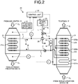
- FIG. 2 is a schematic view of the heat exchanger 20 according to the present embodiment.
- the heat exchanger 20 includes the heat recovery unit 21, the reheater 22, and a steam supply unit 23.
- the heat recovery unit 21 heats the heat medium M by causing the heat medium M to recover the heat from the flue gas G 2 that is introduced from the air heater 13, and discharges the cooled flue gas G 3 after the heat is recovered, to the electronic precipitator 14.
- the reheater 22 heats the wet flue gas G 6 introduced from the desulfurization device 16 with the heat medium M, and discharges the heated flue gas G 7 to the stack 17.
- the steam supply unit 23 supplies steam S to the heat medium M in the circulation line L that supplies the heat medium M from the heat recovery unit 21 toward the reheater 22.
- the heat medium M that is heated by the heat recovery unit 21 is transmitted to the reheater 22 by the liquid feeding pump P through the circulation line L.
- the heat medium M that is cooled by the reheater 22 is transmitted to the heat recovery unit 21 by the liquid feeding pump P through the circulation line L.
- the heat medium M is supplied to the circulation line L that supplies the heat medium M from the reheater 22 toward the heat recovery unit 21, from a heat medium tank 24 as required.
- the fin tube 21a is disposed inside the heat recovery unit 21.
- the fin tube 21a is a heat transfer tube obtained by providing a plurality of fins that are heat sinks on a tube-shaped member.
- the circulation line L for circulating the heat medium M between the heat recovery unit 21 and the reheater 22 is connected to the fin tube 21a.
- the heat exchanger 20 heats the heat medium M by causing the heat medium M to recover the heat from the flue gas G 2 by first heat exchange in which the flue gas G 2 introduced into the heat recovery unit 21 from the air heater 13 is brought into contact with the fin tube 21a.
- the heated heat medium M is transmitted toward the reheater 22 by the liquid feeding pump P provided on the circulation line L.
- the reheater 22 includes the preheating unit 221, the low-temperature heating unit 222, and the high-temperature heating unit 223.
- the preheating unit 221 includes the tube 221a as the heat transfer bare tube that is a tube-shaped member.
- the low-temperature heating unit 222 includes the fin tube 222a as the heat transfer tube obtained by providing the fins that are heat sinks on a tube-shaped member.
- the high-temperature heating unit 223 includes the fin tube 223a as the heat transfer tube obtained by providing the fins that are heat sinks on a tube-shaped member.
- One end of the tube 221a is connected to the circulation line L, and the other end of the tube 221a is connected to an end of the fin tube 223a via the circulation line L.
- the other end of the fin tube 223a is connected to one end of the fin tube 222a via the circulation line L.
- the other end of the fin tube 222a is connected to the circulation line L.
- the preheating unit 221 heats the flue gas G 6 and reduces the humidity of the wet flue gas G 6 , by second heat exchange in which the wet flue gas G 6 introduced to the reheater 22 from the desulfurization device 16 is brought into contact with the heated heat medium M after the first heat exchange that is supplied from the heat recovery unit 21.
- the preheating unit 221 also cools the heat medium M.
- the preheating unit 221 further supplies the flue gas G 6 after the second heat exchange and the humidity of which is reduced, to the low-temperature heating unit 222 and the high-temperature heating unit 223.
- the preheating unit 221 also supplies the cooled heat medium M after the second heat exchange to the high-temperature heating unit 223.
- the low-temperature heating unit 222 further heats the flue gas G 6 by third heat exchange in which the flue gas G 6 supplied from the preheating unit 221 is brought into contact with the heat medium M supplied from the high-temperature heating unit 223.
- the low-temperature heating unit 222 also cools the heat medium M.
- the wet flue gas G 6 is heated by the preheating unit 221 and is turned into the flue gas G 6 the humidity of which is reduced. Consequently, it is possible to prevent dust accompanying the flue gas G 6 from adhering to the tube 221a of the preheating unit 221, and corrosion of the tube 221a of the preheating unit 221 caused by the mist.
- the low-temperature heating unit 222 supplies the flue gas G 6 after the third heat exchange to the high-temperature heating unit 223, and supplies the cooled heat medium M after the third heat exchange to the heat recovery unit 21.
- the high-temperature heating unit 223 further heats the flue gas G 6 that is heated by fourth heat exchange in which the heated flue gas G 6 that is supplied from the low-temperature heating unit 222 is brought into contact with the heat medium M after the second heat exchange that is supplied from the preheating unit 221.
- the high-temperature heating unit 223 also cools the heat medium M.
- the high-temperature heating unit 223 further supplies the flue gas G 7 after the third heat exchange to the stack 17, and supplies the cooled heat medium M after the third heat exchange to the heat recovery unit 21.
- the flue gas G 6 supplied from the preheating unit 221 is heated to sufficient temperature by the low-temperature heating unit 222 and the high-temperature heating unit 223.
- the steam supply unit (heating unit) 23 supplies the steam S toward a heat exchanging unit 25 that is provided on the circulation line L for supplying the heat medium M toward the reheater 22 from the heat recovery unit 21 through a steam supply line L 1 .
- a flow control valve V 1 for controlling the flow of steam supplied to the heat exchanging unit 25 from the steam supply unit 23 is provided on the steam supply line L 1 .
- the heat exchanger 20 can sufficiently heat the wet flue gas G 6 in the preheating unit 221 of the reheater 22. Consequently, it is possible to prevent dust in the flue gas G 6 from adhering to the tube 221a of the preheating unit 221, and corrosion of the tube 221a caused by the mist.
- the heat exchanger 20 includes a flue gas measurement unit 31 and a control unit 32.
- the flue gas measurement unit 31 is provided on an introduction portion of the flue gas G 2 that is introduced to the heat recovery unit 21 from the air heater 13, in the heat recovery unit 21.
- the control unit 32 controls the temperature of the heat medium M that flows in the circulation line L on the basis of a measurement value measured by the flue gas measurement unit 31.
- the flue gas measurement unit 31 measures the gas flow of the flue gas G 2 introduced into the heat recovery unit 21, the gas temperature of the flue gas G 2 , and the like and transmits the measurement values to the control unit 32.
- the control unit 32 calculates the recovered heat quantity that is to be recovered to the heat medium M from the flue gas G 2 through the first heat exchange by the heat exchanger 20, from introduction conditions of the flue gas G 2 to the heat recovery unit 21.
- the introduction conditions are based on the various measurement values transmitted from the flue gas measurement unit 31; air volume supplied to an induced draft fan (IDF, not illustrated) that blows the flue gas G 0 after combustion from the boiler 11, a boost up fan (BUF, not illustrated) provided on the desulfurization device 16, as well as the boiler 11; combustion load of the boiler 11; and the like.
- the control unit 32 then controls the flow of the steam S supplied to the heat medium M by the steam supply unit 23 and the flow control valve V 1 so that the temperature at an outlet portion of the circulation line L from the heat recovery unit 21 that is measured by a temperature measurement device T 1 will fall within a predetermined range, on the basis of the calculated recovered heat quantity.
- the heat exchanger 20 can speedily calculate the recovered heat quantity through the first heat exchange by the heat exchanger 20, on the basis of the introduction conditions of the flue gas G 2 to the heat recovery unit 21 that is calculated by the control unit 32. Because it is possible to set temperature T 2 at the outlet portion of the heat recovery unit 21 and temperature T 3 at the outlet portion of the reheater 22 within a predetermined range, even if the heat quantity recovered by the heat exchanger 20 is changed, it is possible to set the temperature of the heat medium M to be supplied to the preheating unit 221 of the reheater 22 within a predetermined range at an early stage. Consequently, it is possible to prevent dust from adhering to the tube 221a of the preheating unit 221, and corrosion of the tube 221a of the preheating unit 221 at an early stage.
- FIG. 3 is a flow chart of the method for controlling the heat exchanger 20 according to the present embodiment.
- the method for controlling the heat exchanger 20 according to the present embodiment includes a first step of calculating the heat quantity recovered by the heat exchanger 20, a second step of determining whether the calculated recovered heat quantity is less than a predetermined value, a third step of starting supplying the steam S to the heat medium M when the calculated recovered heat quantity is less than the predetermined value, and a fourth step (step ST14) of stopping supplying the steam S to the heat medium M when the calculated recovered heat quantity exceeds the predetermined value.
- the control unit 32 calculates the recovered heat quantity that is to be recovered to the heat medium M from the flue gas G 2 through the first heat exchange by the heat exchanger 20, from introduction conditions of the flue gas G 2 to the heat recovery unit 21 (step ST11).
- the introduction conditions are based on the various measurement values transmitted from the flue gas measurement unit 31; air volume supplied to the induced draft fan (IDF, not illustrated) that blows the flue gas G 0 after combustion from the boiler 11, the boost up fan (BUF, not illustrated) provided on the desulfurization device 16, as well as the boiler 11; combustion load of the boiler 11; and the like.
- the control unit 32 determines whether the calculated recovered heat quantity is less than a predetermined value, by comparing the calculated recovered heat quantity with a predetermined threshold set in advance (step ST12).
- the control unit 32 starts supplying the steam S from the steam supply unit 23, and supplies the steam S to the heat medium M in the circulation line L by opening the flow control valve V 1 of the steam supply line L 1 (step ST13). In this manner, it is possible to set the temperature of the heat medium M to be supplied to the preheating unit 221 of the reheater 22 within a predetermined range.
- the control unit 32 stops supplying the steam S from the steam supply unit 23 and stops supplying the steam S to the heat medium M in the circulation line L by closing the flow control valve V 1 of the steam supply line L 1 (step ST14).
- the temperature of the heat medium M to be supplied to the preheating unit 221 of the reheater 22 is controlled on the basis of the recovered heat quantity that is recovered by the heat recovery unit 21 from the flue gas G 2 introduced into the heat recovery unit 21. Consequently, it is possible to set the temperature of the heat medium M to be supplied to the preheating unit 221 within a predetermined range without delay, according to the change in the recovered heat quantity that is recovered by the heat recovery unit 21 from the flue gas G 2 .
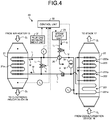
- FIG. 4 is a schematic view of the heat exchanger 20 according to the second embodiment of the present invention.
- the heat exchanger 20 according to the present embodiment includes a bypass line L 2 provided between the circulation line L for supplying the heat medium M to the heat recovery unit 21 from the reheater 22, and the circulation line L for supplying the heat medium M to the reheater 22 from the heat recovery unit 21.
- a flow control valve V 2 for adjusting the flow of the heat medium M that flows in the bypass line L 2 is provided on the bypass line L 2 .
- the flow control valve V 2 is openable and closable by the control unit 32.
- the control unit 32 adjusts the opening degree of the flow control valve V 2 according to the heat quantity recovered by the heat recovery unit 21 that is calculated by the control unit 32.
- the control unit 32 adjusts the opening degree of the flow control valve V 2 according to the heat quantity recovered by the heat recovery unit 21 that is calculated by the control unit 32.
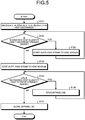
- FIG. 5 is a flow chart of the method for controlling the heat exchanger 20 according to the present embodiment.
- the method for controlling the heat exchanger 20 according to the present embodiment includes a first step of calculating the heat quantity recovered by the heat exchanger 20, a second step of determining whether the calculated recovered heat quantity is less than a predetermined range, a third step of starting supplying the steam S to the heat medium M when the calculated recovered heat quantity is less than the predetermined range, a fourth step of stopping supplying the steam S to the heat medium M when the calculated recovered heat quantity falls within the predetermined range, a fifth step of determining whether the calculated recovered heat quantity exceeds the predetermined range, a sixth step of opening the bypass line L 2 when the calculated recovered heat quantity exceeds the predetermined range, and a seventh step of closing the bypass line L 2 when the calculated recovered heat quantity falls within the predetermined range.
- the control unit 32 calculates the recovered heat quantity that is to be recovered to the heat medium M from the flue gas G 2 through the first heat exchange by the heat exchanger 20, from introduction conditions of the flue gas G 2 to the heat recovery unit 21 (step ST21).
- the introduction conditions are based on the various measurement values transmitted from the flue gas measurement unit 31; air volume supplied to the induced draft fan (IDF, not illustrated) that blows the flue gas G 0 after combustion from the boiler 11, the boost up fan (BUF, not illustrated) provided on the desulfurization device 16, as well as the boiler 11; combustion load of the boiler 11; and the like.
- the control unit 32 determines whether the calculated recovered heat quantity is less than the predetermined range by comparing the calculated recovered heat quantity with a predetermined threshold set in advance (step ST22).
- the control unit 32 starts supplying the steam S from the steam supply unit 23, and supplies the steam S to the heat medium M in the circulation line L by opening the flow control valve V 1 of the steam supply line L 1 (step ST23). In this manner, it is possible to set the temperature of the heat medium M supplied to the preheating unit 221 of the reheater 22 within a predetermined range.
- the control unit 32 stops supplying the steam S from the steam supply unit 23, and stops supplying the steam S to the heat medium M in the circulation line L by closing the flow control valve V 1 of the steam supply line L 1 (step ST24).
- the control unit 32 determines whether the calculated recovered heat quantity exceeds the predetermined range by comparing the calculated recovered heat quantity with a predetermined threshold set in advance (step ST25).
- the control unit 32 opens the flow control valve V 2 of the bypass line L 2 and circulates a part of the heat medium M to the reheater 22 through the bypass line L 2 without via the heat recovery unit 21 (step ST26).
- the heat exchanger 20 can prevent the excessive recovery of heat quantity from the flue gas G 2 to be introduced into the heat recovery unit 21. Consequently, it is possible to set the temperature of the heat medium M to be supplied to the preheating unit 221 of the reheater 22 within a predetermined range.
- control unit 32 closes the flow control valve V 2 of the bypass line L2, and circulates the heat medium M between the reheater 22 and the heat recovery unit 21 without via the bypass line L 2 (step ST27).
- the temperature of the heat medium M to be supplied to the preheating unit 221 of the reheater 22 and the supply of the heat medium M to the heat recovery unit 21 are controlled, on the basis of whether the recovered heat quantity that is recovered by the heat recovery unit 21 from the flue gas G 2 introduced into the heat recovery unit 21 falls within a predetermined range. Consequently, even if the recovered heat quantity that is recovered by the heat recovery unit 21 from the flue gas G 2 is equal to or more than the predetermined value, it is possible to set the temperature of the heat medium M to be supplied to the preheating unit 221 within a predetermined range without delay, according to the change in the recovered heat quantity that is recovered by the heat recovery unit 21 from the flue gas G 2 .
- the arrangement configuration of the tube 221a of the preheating unit 221, the fin tube 222a of the low-temperature heating unit 222, and the fin tube 223a of the high-temperature heating unit 223 in the reheater 22 of the first embodiment and the second embodiment described above is not particularly limited as long as it is possible to heat the flue gas G 6 to be introduced into the reheater 22 to a predetermined temperature.
- FIG. 6A is a diagram illustrating an example of a configuration of the reheater 22.
- FIG. 6A is a schematic view of a vertical section of a plurality of the tubes 221a, the fin tubes 222a, and the fin tubes 223a of the preheating unit 221, the low-temperature heating unit 222, and the high-temperature heating unit 223 of the reheater 22 relative to the extending direction of the tubes 221a, the fin tubes 222a, and the fin tubes 223a.
- the tubes 221a, the fin tubes 222a, and the fin tubes 223a of the preheating unit 221, the low-temperature heating unit 222, and the high-temperature heating unit 223 may be arranged in a lattice pattern relative to the flowing direction of the flue gas G 6 and the flue gas G 7 in the sectional view, respectively.
- the contact area of the tubes 221a, the fin tubes 222a, and the fin tubes 223a relative to the flue gas G 6 that is introduced into the reheater 22 is increased. Consequently, it is possible to efficiently heat the flue gas G 6 and discharge the flue gas G 6 as the flue gas G 7 .
- FIG. 6B is a diagram illustrating another example of the configuration of the reheater 22. Similar to FIG. 6A, FIG. 6B is a schematic view of a vertical section of the tubes 221a, the fin tubes 222a, and the fin tubes 223a of the preheating unit 221, the low-temperature heating unit 222, and the high-temperature heating unit 223 of the reheater 22 relative to the extending direction of the tubes 221a, the fin tubes 222a, and the fin tubes 223a.
- the tubes 221a and the fin tubes 223a of the preheating unit 221 and the high-temperature heating unit 223 are arranged in a lattice pattern relative to the flowing direction of the flue gas G 6 and the flue gas G 7 in the sectional view, respectively.
- the fin tubes 222a of the low-temperature heating unit 222 are arranged in a tetragonal lattice pattern relative to the flowing direction of the flue gas G 6 and the flue gas G 7 in the sectional view, respectively.
- the contact area between the flue gas G 6 and the fin tubes 222a can be moderately reduced, thereby improving the flow velocity of the flue gas G 6 that passes through the low-temperature heating unit 222.
- the fin tubes 222a of the low-temperature heating unit 222 are arranged in a tetragonal lattice pattern.
- the fin tubes 223a of the high-temperature heating unit 223 may also be arranged in a tetragonal lattice pattern.
- the gas flow velocity of the flue gas G 6 that flows through the high-temperature heating unit 223 is further improved. Consequently, it is possible to efficiently heat the flue gas G 6 and discharge the flue gas G 6 as the flue gas G 7 .
Landscapes
- Engineering & Computer Science (AREA)
- Mechanical Engineering (AREA)
- General Engineering & Computer Science (AREA)
- Chemical & Material Sciences (AREA)
- Combustion & Propulsion (AREA)
- Chimneys And Flues (AREA)
- Treating Waste Gases (AREA)
Abstract
Description
- The present invention relates to a heat exchanger and a method for controlling the heat exchanger, for example, a heat exchanger that includes a preheating unit for preheating flue gas introduced into a reheater and a method for controlling the heat exchanger.
- An air pollution control device is used in thermal power plants and chemical plants. In the air pollution control device, a denitration device, an air preheating unit air heater, a heat recovery unit of a reheating heat exchanger (gas-gas heater), a dry electronic precipitator, a wet desulfurization device, a reheater of the reheating heat exchanger, and a stack are sequentially provided from the upstream side toward the downstream side of a flue gas flow path. A gas-gas heater including a preheating unit that is provided on a flue gas introduction portion of a reheater and that preheats flue gas introduced into the reheater body has been developed as the heat exchanger used in the air pollution control device such as the above (for example, see Patent Literature 1). In the gas-gas heater disclosed in
Patent Literature 1, wet flue gas that has passed through the wet desulfurization device is preheated and dried in the preheating unit supplied with a heat medium having been heated by the heat recovery unit and the heating unit. Because the flue gas is dried, it is possible to reduce dust in the flue gas from adhering to the inside of the reheater body and reduce corrosion inside of the reheater body resulting from wet components in the flue gas. - Patent Literature 1: Japanese Laid-open Patent Publication No.
2011-094901 - In the gas-gas heater disclosed in
Patent Literature 1, the heat exchanger is controlled so that the temperature of the flue gas at the flue gas outlet portion of the heat recovery unit and the temperature of the heat medium at the heat medium outlet portion of the reheater will fall within respective predetermined ranges. - However, in the thermal power plants and the like, the gas temperature and the gas flow of the flue gas introduced into the air pollution control device may be reduced by the variation in the power generation load corresponding to the change in the operating conditions. Moreover, the temperature of the heat medium at the heat medium inlet portion of the reheater may be reduced by the change in the heat quantity of the flue gas recovered by the heat recovery unit. When the temperature of the heat medium at the heat medium inlet portion (preheating unit) of the reheater is reduced in this manner, the flue gas in the preheating unit of the reheater will not be sufficiently preheated. Thus, dust accompanying the wet flue gas from the desulfurization device easily adheres to a heat transfer tube in the reheater by using the mist in the flue gas as a binder. Consequently, the gas differential pressure between the inlet portion and the outlet portion of the reheater may be increased and corrosion inside the reheater may be accelerated.
- The present invention has been made in view of the above circumstances, and an object of the present invention is to provide a heat exchanger and a method for controlling the heat exchanger capable of reducing dust in the flue gas from adhering to the inside of the reheater and reducing corrosion of the heat transfer tube, even if the operating conditions have changed.
- A heat exchanger, comprising: a heat recovery unit that causes a heat medium to recover heat from flue gas from a combustion engine through first heat exchange by bringing the flue gas into contact with a heat transfer tube in which the heat medium flows; a reheater that includes a preheating unit configured to preheat the flue gas after the first heat exchange through second heat exchange by bringing the flue gas after the first heat exchange into contact with the heat transfer tube in which the heat medium after the first heat exchange flows, and a heating unit configured to heat the flue gas after the second heat exchange through third heat exchange by bringing the flue gas after the second heat exchange into contact with the heat medium after the second heat exchange; a circulation line that circulates the heat medium between the heat recovery unit and the reheater; and a control unit that calculates a recovered heat quantity to be recovered by the heat recovery unit from the flue gas through the first heat exchange, and that controls temperature of the heat medium after the first heat exchange within a predetermined range based on the calculated recovered heat quantity.
- With this configuration, the temperature of the heat medium to be supplied to the preheating unit of the reheater is controlled on the basis of the recovered heat quantity that is recovered by the heat recovery unit from the flue gas introduced into the heat recovery unit. Consequently, it is possible to set the temperature of the heat medium to be supplied to the preheating unit within a predetermined range without delay, according to the change in the recovered heat quantity that is recovered by the heat recovery unit from the flue gas. In this manner, even if the operating conditions of a boiler and the like have changed, it is possible to implement the heat exchanger and the method for controlling the heat exchanger capable of reducing dust in the flue gas from adhering to the inside of the reheater, and reduce corrosion of the heat transfer tube of the preheating unit.
- In the heat exchanger according to present invention, it is preferable that the control unit calculates the recovered heat quantity based on at least one type selected from the group consisting of gas temperature of the flue gas introduced into the heat exchanger, a gas flow of the flue gas, and operation load of the combustion engine. With this configuration, the accuracy of the recovered heat quantity calculated by the control unit will be improved. Consequently, it is possible to further reduce dust in the flue gas from adhering to the inside of the reheater and reduce corrosion of the heat transfer tube of the preheating unit.
- In the heat exchanger according to present invention, it is preferable that the control unit heats the heat medium after the first heat exchange, when the recovered heat quantity is less than a predetermined value.
- With this configuration, the heat medium can be heated according to the recovered heat quantity. Consequently, it is possible to reduce dust in the flue gas from adhering to the inside of the reheater and reduce corrosion of the heat transfer tube of the preheating unit.
- In the heat exchanger according to present invention, it is preferable that the control unit supplies steam to the heat medium after the first heat exchange from a steam supply unit, and sets the temperature of the heat medium after the first heat exchange within the predetermined range. With this configuration, the heat medium can be heated by steam. Consequently, it is possible to easily heat the heat medium.
- In the heat exchanger according to present invention, it is preferable that the circulation line includes a bypass line that bypasses the heat recovery unit, and the control unit sets the temperature of the heat medium within the predetermined range, by circulating the heat medium between the heat recovery unit and the reheater via the bypass line, when the recovered heat quantity exceeds the predetermined value. With this configuration, even if the heat quantity recovered by the heat recovery unit is too large, it is possible to reduce the heat quantity recovered by the heat recovery unit, and set the temperature of the heat medium within a predetermined range.
- In the heat exchanger according to present invention, it is preferable that in the reheater, a plurality of heat transfer tubes of the heating unit are arranged in a tetragonal lattice pattern relative to a flowing direction of the flue gas. With this configuration, the gas flow velocity of the flue gas of the heating unit will be improved. Consequently, it is possible to further reduce dust in the flue gas from adhering to the heating unit and reduce corrosion of a pipe.
- A method for controlling a heat exchanger that includes a heat recovery unit that causes a heat medium to recover heat from flue gas from a combustion engine through first heat exchange by bringing the flue gas into contact with a heat transfer tube in which the heat medium flows; and a reheater that includes a preheating unit configured to preheat the flue gas after the first heat exchange using heat of the heat medium after the first heat exchange through second heat exchange by bringing the flue gas after the first heat exchange into contact with the heat transfer tube in which the heat medium after the first heat exchange flows, and a heating unit configured to heat the flue gas after the second heat exchange through third heat exchange by bringing the flue gas after the second heat exchange into contact with the heat medium after the second heat exchange, the method for controlling the heat exchanger, comprising: a step of calculating a recovered heat quantity to be recovered by the heat recovery unit from the flue gas through the first heat exchange; and a step of controlling temperature of the heat medium within a predetermined range by heating the heat medium after the first heat exchange, when the calculated recovered heat quantity becomes less than a predetermined value.
- With this method, the temperature of the heat medium to be supplied to the preheating unit of the reheater is controlled on the basis of the recovered heat quantity that is recovered by the heat recovery unit from the flue gas introduced into the heat recovery unit. Consequently, it is possible to set the temperature of the heat medium to be supplied to the preheating unit within a predetermined range without delay, according to the change in the recovered heat quantity that is recovered by the heat recovery unit from the flue gas. In this manner, even if the operating conditions of the boiler and the like have changed, it is possible to implement the heat exchanger and the method for controlling the heat exchanger capable of reducing dust in the flue gas from adhering to the inside of the reheater, and reduce corrosion of the heat transfer tube of the preheating unit. With this configuration, even if the heat quantity recovered by the heat recovery unit is too large, it is possible to reduce the heat quantity recovered by the heat recovery unit, and set the temperature of the heat medium within a predetermined range.
- In the method for controlling a heat exchanger according to present invention, it is preferable that the method further comprising a step of controlling the temperature of the heat medium within the predetermined range by making the heat medium flow in a bypass line that bypasses the heat recovery unit, when the calculated recovered heat quantity exceeds the predetermined value. Advantageous Effects of Invention
- With the present invention, even if the operating conditions have changed, it is possible to implement the heat exchanger and the method for controlling the heat exchanger capable of reducing dust in the flue gas from adhering to the inside of the reheater and reduce corrosion of the heat transfer tube.
-
-
FIG. 1 is schematic diagram of an air pollution control system according to a first embodiment of the present invention. -
FIG. 2 is a schematic view of a heat exchanger according to the first embodiment of the present invention. -
FIG. 3 is a flow chart of a method for controlling the heat exchanger according to the first embodiment of the present invention. -
FIG. 4 is a schematic view of a heat exchanger according to a second embodiment of the present invention. -
FIG. 5 is a flow chart of a method for controlling the heat exchanger according to the embodiment of the present invention. -
FIG. 6A is a diagram illustrating an example of a configuration of a reheater according to the embodiment of the present invention. -
FIG. 6B is a diagram illustrating another example of the configuration of the reheater according to the embodiment of the present invention. - Hereinafter, embodiments of the present invention will be described in detail with reference to the accompanying drawings. It is to be understood that the present invention is not limited to the following embodiments and may be implemented by suitably modifying the embodiments. Moreover, the present invention may be implemented by suitably combining the following embodiments. Furthermore, the same reference numerals denote the same components in the embodiments, and the repeated description will be omitted.
-
FIG. 1 is a schematic diagram of an air pollution control system 10 according to a first embodiment of the present invention. As illustrated inFIG. 1 , the air pollution control system 10 according to the present embodiment is an air pollution control system that treats flue gas discharged from a thermal power plant, a chemical plant, or the like, and that removes nitrogen oxides (NOx), dust, and sulfur oxides (SOx) included in the flue gas to discharge. - The air pollution control system 10 according to the present embodiment includes a
boiler 11 installed in a thermal power plant, a chemical plant, and the like, adenitration device 12 provided at a subsequent stage of theboiler 11, an air heater (AH) 13 provided at a subsequent stage of thedenitration device 12, and anelectronic precipitator 14 provided at a subsequent stage of theair heater 13. The air pollution control system 10 also includes anair blower 15 provided at a subsequent stage of theelectronic precipitator 14, adesulfurization device 16 provided at a subsequent stage of theair blower 15, and astack 17 provided at a subsequent stage of thedesulfurization device 16. - A
heat recovery unit 21 of aheat exchanger 20 according to the present embodiment is disposed between theair heater 13 and theelectronic precipitator 14. Areheater 22 of the heat exchanger (gas-gas heater) 20 according to the present embodiment is disposed between thedesulfurization device 16 and thestack 17. Afin tube 21a as a heat transfer tube in which a heat medium flows is provided inside theheat recovery unit 21. Thereheater 22 includes apreheating unit 221 that preheats the flue gas introduced into thereheater 22, a low-temperature heating unit 222 that heats the flue gas preheated by the preheatingunit 221, and a high-temperature heating unit 223 that further heats the flue gas heated by the low-temperature heating unit 222. Atube 221a is disposed inside the preheatingunit 221 as a heat transfer bare tube. Afin tube 222a is disposed inside the low-temperature heating unit 222 as a heat transfer tube. Afin tube 223a is disposed inside the high-temperature heating unit 223 as a heat transfer tube. A circulation line L that circulates a heat medium M between theheat recovery unit 21 and thereheater 22 is provided between theheat recovery unit 21 and thereheater 22. A liquid feeding pump P that circulates the heat medium M in the circulation line L between theheat recovery unit 21 and thereheater 22 is provided on the circulation line L. Heat exchange is performed between theheat recovery unit 21 and thereheater 22, using the heat medium M that flows in the circulation line L by the liquid feeding pipe P. - Flue gas G0 discharged from the
boiler 11 is introduced into thedenitration device 12 filled with a catalyst. The flue gas G0 introduced into thedenitration device 12 is made harmless by reducing the nitrogen oxides included in the flue gas G0 to water and nitrogen, with ammonia (NH3) injected into thedenitration device 12 as a reducing agent. - Flue gas G1 discharged from the
denitration device 12 is introduced into the air heater (AH) 13. For example, the temperature of the flue gas G1 introduced into theair heater 13 is cooled to equal to or more than 130 degrees Celsius and equal to or less than 150 degrees Celsius, by heat exchange with air. - Flue gas G2 discharged from the
air heater 13 is introduced into theheat recovery unit 21 of the heat exchanger (gas-gas heater) 20 according to the present embodiment. The heat of the flue gas G2 introduced into theheat recovery unit 21 is recovered and cooled by heat exchange with a heat medium (such as water), when the flue gas G2 is brought into contact with thefin tube 21a in which the heat medium M flows. For example, the temperature of flue gas G3 after the heat exchange in theheat recovery unit 21 is equal to or more than 85 degrees Celsius and equal to or less than 110 degrees Celsius. - The flue gas G3 discharged from the
heat recovery unit 21 is introduced into the electronic precipitator (EP) 14 to remove dust. In this example, dust such as fly ash in the flue gas G3 that is cooled by heat exchange in theheat recovery unit 21 is removed. Consequently, it is possible to improve the dust collection efficiency of theelectronic precipitator 14. - The
air blower 15 driven by a motor boosts the pressure of flue gas G4 discharged from theelectronic precipitator 14. It is to be understood that theair blower 15 is not necessarily provided. Theair blower 15 may also be provided at a subsequent stage of thereheater 22 of theheat exchanger 20. - Flue gas G5 the pressure of which is boosted by the
air blower 15 is introduced into thedesulfurization device 16. In thedesulfurization device 16, sulfur oxides in the flue gas G5 are absorbed and removed by absorbent in which slurry limestone is dissolved, and gypsum (not illustrated) is generated as a by-product. In this example, flue gas G6 discharged from thedesulfurization device 16 absorbs water in the absorbent and becomes wet. The temperature of the flue gas G6 is reduced to, for example, about 50 degrees Celsius. - The flue gas G6 discharged from the
desulfurization device 16 is introduced into theheat recovery unit 21 of the heat exchanger (gas-gas heater) 20 according to the present embodiment. The flue gas G6 introduced into theheat recovery unit 21 is sequentially brought into contact with thetube 221a, thefin tube 222a, and thefin tube 223a in thepreheating unit 221, the low-temperature heating unit 222, and the high-temperature heating unit 223, and is heated by heat exchange with the heat medium. In this example, the preheatingunit 221 heats the wet flue gas G6 to the temperature exceeding 50 degrees Celsius in advance. Thus, the humidity of the wet flue gas G6 is reduced. Consequently, it is possible to prevent dust accompanying the flue gas G6 from adhering to the low-temperature heating unit 222, and corrosion of the low-temperature heating unit 222 caused by the mist of the absorbent in the flue gas G6 and the like. The flue gas G6 the heat of which is exchanged in thereheater 22 is discharged through thestack 17. -
FIG. 2 is a schematic view of theheat exchanger 20 according to the present embodiment. As illustrated inFIG. 2 , theheat exchanger 20 according to the present embodiment includes theheat recovery unit 21, thereheater 22, and asteam supply unit 23. Theheat recovery unit 21 heats the heat medium M by causing the heat medium M to recover the heat from the flue gas G2 that is introduced from theair heater 13, and discharges the cooled flue gas G3 after the heat is recovered, to theelectronic precipitator 14. Thereheater 22 heats the wet flue gas G6 introduced from thedesulfurization device 16 with the heat medium M, and discharges the heated flue gas G7 to thestack 17. Thesteam supply unit 23 supplies steam S to the heat medium M in the circulation line L that supplies the heat medium M from theheat recovery unit 21 toward thereheater 22. The heat medium M that is heated by theheat recovery unit 21 is transmitted to thereheater 22 by the liquid feeding pump P through the circulation line L. Moreover, the heat medium M that is cooled by thereheater 22 is transmitted to theheat recovery unit 21 by the liquid feeding pump P through the circulation line L. The heat medium M is supplied to the circulation line L that supplies the heat medium M from thereheater 22 toward theheat recovery unit 21, from aheat medium tank 24 as required. - The
fin tube 21a is disposed inside theheat recovery unit 21. Thefin tube 21a is a heat transfer tube obtained by providing a plurality of fins that are heat sinks on a tube-shaped member. The circulation line L for circulating the heat medium M between theheat recovery unit 21 and thereheater 22 is connected to thefin tube 21a. Theheat exchanger 20 heats the heat medium M by causing the heat medium M to recover the heat from the flue gas G2 by first heat exchange in which the flue gas G2 introduced into theheat recovery unit 21 from theair heater 13 is brought into contact with thefin tube 21a. The heated heat medium M is transmitted toward thereheater 22 by the liquid feeding pump P provided on the circulation line L. - The
reheater 22 includes the preheatingunit 221, the low-temperature heating unit 222, and the high-temperature heating unit 223. The preheatingunit 221 includes thetube 221a as the heat transfer bare tube that is a tube-shaped member. The low-temperature heating unit 222 includes thefin tube 222a as the heat transfer tube obtained by providing the fins that are heat sinks on a tube-shaped member. The high-temperature heating unit 223 includes thefin tube 223a as the heat transfer tube obtained by providing the fins that are heat sinks on a tube-shaped member. One end of thetube 221a is connected to the circulation line L, and the other end of thetube 221a is connected to an end of thefin tube 223a via the circulation line L. The other end of thefin tube 223a is connected to one end of thefin tube 222a via the circulation line L. The other end of thefin tube 222a is connected to the circulation line L. In other words, in thereheater 22, the heat medium M after the first heat exchange that is supplied from theheat recovery unit 21 is sequentially transmitted through the preheatingunit 221, the high-temperature heating unit 223, and the low-temperature heating unit 222, in the order of the preheatingunit 221, the high-temperature heating unit 223, and the low-temperature heating unit 222. The heat medium M supplied to the low-temperature heating unit 222 is transmitted to theheat recovery unit 21 through the circulation line L. - The preheating
unit 221 heats the flue gas G6 and reduces the humidity of the wet flue gas G6, by second heat exchange in which the wet flue gas G6 introduced to thereheater 22 from thedesulfurization device 16 is brought into contact with the heated heat medium M after the first heat exchange that is supplied from theheat recovery unit 21. The preheatingunit 221 also cools the heat medium M. The preheatingunit 221 further supplies the flue gas G6 after the second heat exchange and the humidity of which is reduced, to the low-temperature heating unit 222 and the high-temperature heating unit 223. The preheatingunit 221 also supplies the cooled heat medium M after the second heat exchange to the high-temperature heating unit 223. - The low-
temperature heating unit 222 further heats the flue gas G6 by third heat exchange in which the flue gas G6 supplied from the preheatingunit 221 is brought into contact with the heat medium M supplied from the high-temperature heating unit 223. The low-temperature heating unit 222 also cools the heat medium M. In this example, the wet flue gas G6 is heated by the preheatingunit 221 and is turned into the flue gas G6 the humidity of which is reduced. Consequently, it is possible to prevent dust accompanying the flue gas G6 from adhering to thetube 221a of the preheatingunit 221, and corrosion of thetube 221a of the preheatingunit 221 caused by the mist. Moreover, the low-temperature heating unit 222 supplies the flue gas G6 after the third heat exchange to the high-temperature heating unit 223, and supplies the cooled heat medium M after the third heat exchange to theheat recovery unit 21. - The high-
temperature heating unit 223 further heats the flue gas G6 that is heated by fourth heat exchange in which the heated flue gas G6 that is supplied from the low-temperature heating unit 222 is brought into contact with the heat medium M after the second heat exchange that is supplied from the preheatingunit 221. The high-temperature heating unit 223 also cools the heat medium M. The high-temperature heating unit 223 further supplies the flue gas G7 after the third heat exchange to thestack 17, and supplies the cooled heat medium M after the third heat exchange to theheat recovery unit 21. In this example, the flue gas G6 supplied from the preheatingunit 221 is heated to sufficient temperature by the low-temperature heating unit 222 and the high-temperature heating unit 223. Thus, it is possible to prevent white smoke generated from flue gas G7 that is discharged toward thestack 17. - The steam supply unit (heating unit) 23 supplies the steam S toward a
heat exchanging unit 25 that is provided on the circulation line L for supplying the heat medium M toward thereheater 22 from theheat recovery unit 21 through a steam supply line L1. A flow control valve V1 for controlling the flow of steam supplied to theheat exchanging unit 25 from thesteam supply unit 23 is provided on the steam supply line L1. In this manner, when thesteam supply unit 23 supplies the steam S to the heat medium M and heats the heat medium M that flows in the circulation line L, even if the heat quantity recovered by theheat recovery unit 21 from the flue gas G0 that is supplied from theboiler 11 is not sufficient, the heat medium M supplied to thepreheating unit 221 can be heated to a predetermined temperature range. Thus, theheat exchanger 20 can sufficiently heat the wet flue gas G6 in thepreheating unit 221 of thereheater 22. Consequently, it is possible to prevent dust in the flue gas G6 from adhering to thetube 221a of the preheatingunit 221, and corrosion of thetube 221a caused by the mist. - The
heat exchanger 20 according to the present embodiment includes a fluegas measurement unit 31 and acontrol unit 32. The fluegas measurement unit 31 is provided on an introduction portion of the flue gas G2 that is introduced to theheat recovery unit 21 from theair heater 13, in theheat recovery unit 21. Thecontrol unit 32 controls the temperature of the heat medium M that flows in the circulation line L on the basis of a measurement value measured by the fluegas measurement unit 31. - The flue
gas measurement unit 31 measures the gas flow of the flue gas G2 introduced into theheat recovery unit 21, the gas temperature of the flue gas G2, and the like and transmits the measurement values to thecontrol unit 32. Thecontrol unit 32 calculates the recovered heat quantity that is to be recovered to the heat medium M from the flue gas G2 through the first heat exchange by theheat exchanger 20, from introduction conditions of the flue gas G2 to theheat recovery unit 21. The introduction conditions are based on the various measurement values transmitted from the fluegas measurement unit 31; air volume supplied to an induced draft fan (IDF, not illustrated) that blows the flue gas G0 after combustion from theboiler 11, a boost up fan (BUF, not illustrated) provided on thedesulfurization device 16, as well as theboiler 11; combustion load of theboiler 11; and the like. Thecontrol unit 32 then controls the flow of the steam S supplied to the heat medium M by thesteam supply unit 23 and the flow control valve V1 so that the temperature at an outlet portion of the circulation line L from theheat recovery unit 21 that is measured by a temperature measurement device T1 will fall within a predetermined range, on the basis of the calculated recovered heat quantity. In this manner, theheat exchanger 20 can speedily calculate the recovered heat quantity through the first heat exchange by theheat exchanger 20, on the basis of the introduction conditions of the flue gas G2 to theheat recovery unit 21 that is calculated by thecontrol unit 32. Because it is possible to set temperature T2 at the outlet portion of theheat recovery unit 21 and temperature T3 at the outlet portion of thereheater 22 within a predetermined range, even if the heat quantity recovered by theheat exchanger 20 is changed, it is possible to set the temperature of the heat medium M to be supplied to thepreheating unit 221 of thereheater 22 within a predetermined range at an early stage. Consequently, it is possible to prevent dust from adhering to thetube 221a of the preheatingunit 221, and corrosion of thetube 221a of the preheatingunit 221 at an early stage. - Next, a method for controlling the
heat exchanger 20 according to the present embodiment will be described in detail with reference toFIG. 3. FIG. 3 is a flow chart of the method for controlling theheat exchanger 20 according to the present embodiment. As illustrated inFIG. 3 , the method for controlling theheat exchanger 20 according to the present embodiment includes a first step of calculating the heat quantity recovered by theheat exchanger 20, a second step of determining whether the calculated recovered heat quantity is less than a predetermined value, a third step of starting supplying the steam S to the heat medium M when the calculated recovered heat quantity is less than the predetermined value, and a fourth step (step ST14) of stopping supplying the steam S to the heat medium M when the calculated recovered heat quantity exceeds the predetermined value. - First, when the operation of the
heat exchanger 20 has started, thecontrol unit 32 calculates the recovered heat quantity that is to be recovered to the heat medium M from the flue gas G2 through the first heat exchange by theheat exchanger 20, from introduction conditions of the flue gas G2 to the heat recovery unit 21 (step ST11). The introduction conditions are based on the various measurement values transmitted from the fluegas measurement unit 31; air volume supplied to the induced draft fan (IDF, not illustrated) that blows the flue gas G0 after combustion from theboiler 11, the boost up fan (BUF, not illustrated) provided on thedesulfurization device 16, as well as theboiler 11; combustion load of theboiler 11; and the like. - Next, the
control unit 32 determines whether the calculated recovered heat quantity is less than a predetermined value, by comparing the calculated recovered heat quantity with a predetermined threshold set in advance (step ST12). When the calculated recovered heat quantity is less than the predetermined value (Yes at step ST12), thecontrol unit 32 starts supplying the steam S from thesteam supply unit 23, and supplies the steam S to the heat medium M in the circulation line L by opening the flow control valve V1 of the steam supply line L1 (step ST13). In this manner, it is possible to set the temperature of the heat medium M to be supplied to thepreheating unit 221 of thereheater 22 within a predetermined range. Consequently, it is possible to prevent dust parts in the flue gas G6 from adhering to thetube 221a of the preheatingunit 221, and corrosion of thetube 221a of the preheatingunit 221. Moreover, when the calculated recovered heat quantity exceeds the predetermined value (No at step ST12), thecontrol unit 32 stops supplying the steam S from thesteam supply unit 23 and stops supplying the steam S to the heat medium M in the circulation line L by closing the flow control valve V1 of the steam supply line L1 (step ST14). - As described above, with the above embodiment, the temperature of the heat medium M to be supplied to the
preheating unit 221 of thereheater 22 is controlled on the basis of the recovered heat quantity that is recovered by theheat recovery unit 21 from the flue gas G2 introduced into theheat recovery unit 21. Consequently, it is possible to set the temperature of the heat medium M to be supplied to thepreheating unit 221 within a predetermined range without delay, according to the change in the recovered heat quantity that is recovered by theheat recovery unit 21 from the flue gas G2. In this manner, even if the operating conditions of theboiler 11 and the like have changed, it is possible to implement the heat exchanger and the method for controlling the heat exchanger capable of reducing dust in the flue gas G6 from adhering to the inside of thereheater 22, and reduce corrosion of thetube 221a of the preheatingunit 221. - Next, a second embodiment of the present invention will be described. In the following, points different from those in the above-described first embodiment are mainly described, and the repeated description will be omitted.
-
FIG. 4 is a schematic view of theheat exchanger 20 according to the second embodiment of the present invention. As illustrated inFIG. 4 , theheat exchanger 20 according to the present embodiment includes a bypass line L2 provided between the circulation line L for supplying the heat medium M to theheat recovery unit 21 from thereheater 22, and the circulation line L for supplying the heat medium M to thereheater 22 from theheat recovery unit 21. A flow control valve V2 for adjusting the flow of the heat medium M that flows in the bypass line L2 is provided on the bypass line L2. The flow control valve V2 is openable and closable by thecontrol unit 32. In other words, in theheat exchanger 20 according to the present embodiment, thecontrol unit 32 adjusts the opening degree of the flow control valve V2 according to the heat quantity recovered by theheat recovery unit 21 that is calculated by thecontrol unit 32. Thus, it is possible to control the flow of the heat medium M that flows in the bypass line L2. Consequently, even if the gas flow and the gas temperature of the flue gas G2 to be supplied from theair heater 13 is high, it is possible to prevent excessive heat recovery by theheat recovery unit 21 and control the recovered heat quantity to be recovered to the heat medium M within a predetermined range. The other configurations are the same as those in theheat exchanger 20 according to the first embodiment described above, and the description thereof will be omitted. - Next, the method for controlling the
heat exchanger 20 according to the present embodiment will be described in detail with reference toFIG. 5. FIG. 5 is a flow chart of the method for controlling theheat exchanger 20 according to the present embodiment. As illustrated inFIG. 5 , the method for controlling theheat exchanger 20 according to the present embodiment includes a first step of calculating the heat quantity recovered by theheat exchanger 20, a second step of determining whether the calculated recovered heat quantity is less than a predetermined range, a third step of starting supplying the steam S to the heat medium M when the calculated recovered heat quantity is less than the predetermined range, a fourth step of stopping supplying the steam S to the heat medium M when the calculated recovered heat quantity falls within the predetermined range, a fifth step of determining whether the calculated recovered heat quantity exceeds the predetermined range, a sixth step of opening the bypass line L2 when the calculated recovered heat quantity exceeds the predetermined range, and a seventh step of closing the bypass line L2 when the calculated recovered heat quantity falls within the predetermined range. - First, when the operation of the
heat exchanger 20 has started, thecontrol unit 32 calculates the recovered heat quantity that is to be recovered to the heat medium M from the flue gas G2 through the first heat exchange by theheat exchanger 20, from introduction conditions of the flue gas G2 to the heat recovery unit 21 (step ST21). The introduction conditions are based on the various measurement values transmitted from the fluegas measurement unit 31; air volume supplied to the induced draft fan (IDF, not illustrated) that blows the flue gas G0 after combustion from theboiler 11, the boost up fan (BUF, not illustrated) provided on thedesulfurization device 16, as well as theboiler 11; combustion load of theboiler 11; and the like. - The
control unit 32 then determines whether the calculated recovered heat quantity is less than the predetermined range by comparing the calculated recovered heat quantity with a predetermined threshold set in advance (step ST22). When the calculated recovered heat quantity is less than the predetermined range (Yes at step ST22), thecontrol unit 32 starts supplying the steam S from thesteam supply unit 23, and supplies the steam S to the heat medium M in the circulation line L by opening the flow control valve V1 of the steam supply line L1 (step ST23). In this manner, it is possible to set the temperature of the heat medium M supplied to thepreheating unit 221 of thereheater 22 within a predetermined range. Consequently, it is possible prevent the dust parts in the flue gas G6 from adhering to thetube 221a of the preheatingunit 221, and corrosion of thetube 221a of the preheatingunit 221. Moreover, when the calculated recovered heat quantity exceeds the predetermined range (No at step ST22), thecontrol unit 32 stops supplying the steam S from thesteam supply unit 23, and stops supplying the steam S to the heat medium M in the circulation line L by closing the flow control valve V1 of the steam supply line L1 (step ST24). - The
control unit 32 then determines whether the calculated recovered heat quantity exceeds the predetermined range by comparing the calculated recovered heat quantity with a predetermined threshold set in advance (step ST25). When the calculated recovered heat quantity exceeds the predetermined range (Yes at step ST25), thecontrol unit 32 opens the flow control valve V2 of the bypass line L2 and circulates a part of the heat medium M to thereheater 22 through the bypass line L2 without via the heat recovery unit 21 (step ST26). In this manner, theheat exchanger 20 can prevent the excessive recovery of heat quantity from the flue gas G2 to be introduced into theheat recovery unit 21. Consequently, it is possible to set the temperature of the heat medium M to be supplied to thepreheating unit 221 of thereheater 22 within a predetermined range. It is also possible to prevent the dust parts in the flue gas G6 from adhering to thetube 221a of the preheatingunit 221, and corrosion of thetube 221a of the preheatingunit 221. Moreover, when the calculated recovered heat quantity does not fall within the predetermined range (No at step ST25), thecontrol unit 32 closes the flow control valve V2 of the bypass line L2, and circulates the heat medium M between thereheater 22 and theheat recovery unit 21 without via the bypass line L2 (step ST27). - As described above, according to the present embodiment, the temperature of the heat medium M to be supplied to the
preheating unit 221 of thereheater 22 and the supply of the heat medium M to theheat recovery unit 21 are controlled, on the basis of whether the recovered heat quantity that is recovered by theheat recovery unit 21 from the flue gas G2 introduced into theheat recovery unit 21 falls within a predetermined range. Consequently, even if the recovered heat quantity that is recovered by theheat recovery unit 21 from the flue gas G2 is equal to or more than the predetermined value, it is possible to set the temperature of the heat medium M to be supplied to thepreheating unit 221 within a predetermined range without delay, according to the change in the recovered heat quantity that is recovered by theheat recovery unit 21 from the flue gas G2. In this manner, even if the operating conditions of theboiler 11 and the like have changed, it is possible to implement the heat exchanger and the method for controlling the heat exchanger capable of reducing dust in the flue gas G6 from adhering to the inside of thereheater 22, and reduce corrosion of thetube 221a of the preheatingunit 221. - The arrangement configuration of the
tube 221a of the preheatingunit 221, thefin tube 222a of the low-temperature heating unit 222, and thefin tube 223a of the high-temperature heating unit 223 in thereheater 22 of the first embodiment and the second embodiment described above is not particularly limited as long as it is possible to heat the flue gas G6 to be introduced into thereheater 22 to a predetermined temperature. -
FIG. 6A is a diagram illustrating an example of a configuration of thereheater 22.FIG. 6A is a schematic view of a vertical section of a plurality of thetubes 221a, thefin tubes 222a, and thefin tubes 223a of the preheatingunit 221, the low-temperature heating unit 222, and the high-temperature heating unit 223 of thereheater 22 relative to the extending direction of thetubes 221a, thefin tubes 222a, and thefin tubes 223a. - As illustrated in
FIG. 6A , thetubes 221a, thefin tubes 222a, and thefin tubes 223a of the preheatingunit 221, the low-temperature heating unit 222, and the high-temperature heating unit 223 may be arranged in a lattice pattern relative to the flowing direction of the flue gas G6 and the flue gas G7 in the sectional view, respectively. By arranging in this manner, the contact area of thetubes 221a, thefin tubes 222a, and thefin tubes 223a relative to the flue gas G6 that is introduced into thereheater 22 is increased. Consequently, it is possible to efficiently heat the flue gas G6 and discharge the flue gas G6 as the flue gas G7. -
FIG. 6B is a diagram illustrating another example of the configuration of thereheater 22. Similar toFIG. 6A, FIG. 6B is a schematic view of a vertical section of thetubes 221a, thefin tubes 222a, and thefin tubes 223a of the preheatingunit 221, the low-temperature heating unit 222, and the high-temperature heating unit 223 of thereheater 22 relative to the extending direction of thetubes 221a, thefin tubes 222a, and thefin tubes 223a. - In the example illustrated in
FIG. 6B , thetubes 221a and thefin tubes 223a of the preheatingunit 221 and the high-temperature heating unit 223 are arranged in a lattice pattern relative to the flowing direction of the flue gas G6 and the flue gas G7 in the sectional view, respectively. Moreover, thefin tubes 222a of the low-temperature heating unit 222 are arranged in a tetragonal lattice pattern relative to the flowing direction of the flue gas G6 and the flue gas G7 in the sectional view, respectively. By arranging in this manner, the contact area of thetubes 221a and thefin tubes 223a relative to the flue gas G6 introduced into thereheater 22 is increased, and a sufficient contact area can be obtained. Moreover, in the low-temperature heating unit 222, the contact area between the flue gas G6 and thefin tubes 222a can be moderately reduced, thereby improving the flow velocity of the flue gas G6 that passes through the low-temperature heating unit 222. Thus, it is possible to efficiently heat the flue gas G6 and discharge the flue gas G6 as the flue gas G7. In this manner, it is possible to prevent dust in the flue gas G6 from adhering to thefin tube 222a of the low-temperature heating unit 222, and corrosion of thefin tube 222a of the low-temperature heating unit 222 caused by the mist, while securing sufficient heat exchange efficiency in thepreheating unit 221 and the high-temperature heating unit 223. In the example illustrated inFIG. 6B , only thefin tubes 222a of the low-temperature heating unit 222 are arranged in a tetragonal lattice pattern. However, thefin tubes 223a of the high-temperature heating unit 223 may also be arranged in a tetragonal lattice pattern. In this case, the gas flow velocity of the flue gas G6 that flows through the high-temperature heating unit 223 is further improved. Consequently, it is possible to efficiently heat the flue gas G6 and discharge the flue gas G6 as the flue gas G7. As a result, it is also possible to further reduce dust from adhering to thefin tube 222a of the low-temperature heating unit 222 and reduce corrosion of thefin tube 222a of the low-temperature heating unit 222 caused by the mist. -
- 10 air pollution control system
- 11 boiler
- 12 denitration device
- 13 air heater
- 14 electronic precipitator
- 15 air blower
- 16 desulfurization device
- 17 stack
- 20 heat exchanger
- 21 heat recovery unit
- 21a fin tube
- 22 reheater
- 221 preheating unit
- 222 low-temperature heating unit
- 223 high-temperature heating unit
- 221a tube
- 222a, 223a fin tube
- G0, G1, G2, G3, G4, G5, G6, G7 flue gas
- L circulation line
- L1 steam supply line
- M heat medium
- P liquid feeding pump
- S steam
- V1, V2 flow control valve
Claims (8)
- A heat exchanger, comprising:a heat recovery unit that causes a heat medium to recover heat from flue gas from a combustion engine through first heat exchange by bringing the flue gas into contact with a heat transfer tube in which the heat medium flows;a reheater that includes a preheating unit configured to preheat the flue gas after the first heat exchange through second heat exchange by bringing the flue gas after the first heat exchange into contact with the heat transfer tube in which the heat medium after the first heat exchange flows, and a heating unit configured to heat the flue gas after the second heat exchange through third heat exchange by bringing the flue gas after the second heat exchange into contact with the heat medium after the second heat exchange;a circulation line that circulates the heat medium between the heat recovery unit and the reheater; anda control unit that calculates a recovered heat quantity to be recovered by the heat recovery unit from the flue gas through the first heat exchange, and that controls temperature of the heat medium after the first heat exchange within a predetermined range based on the calculated recovered heat quantity.
- The heat exchanger according to claim 1, wherein the control unit calculates the recovered heat quantity based on at least one type selected from the group consisting of gas temperature of the flue gas introduced into the heat exchanger, a gas flow of the flue gas, and operation load of the combustion engine.
- The heat exchanger according to claim 1 or 2, wherein the control unit heats the heat medium after the first heat exchange, when the recovered heat quantity is less than a predetermined value.
- The heat exchanger according to claim 3, wherein the control unit supplies steam to the heat medium after the first heat exchange from a steam supply unit, and sets the temperature of the heat medium after the first heat exchange within the predetermined range.
- The heat exchanger according to any one of claims 1 to 4, wherein
the circulation line includes a bypass line that bypasses the heat recovery unit, and
the control unit sets the temperature of the heat medium within the predetermined range, by circulating the heat medium between the heat recovery unit and the reheater via the bypass line, when the recovered heat quantity exceeds the predetermined value. - The heat exchanger according to any one of claims 1 to 5, wherein in the reheater, a plurality of heat transfer tubes of the heating unit are arranged in a tetragonal lattice pattern relative to a flowing direction of the flue gas.
- A method for controlling a heat exchanger that includes
a heat recovery unit that causes a heat medium to recover heat from flue gas from a combustion engine through first heat exchange by bringing the flue gas into contact with a heat transfer tube in which the heat medium flows; and
a reheater that includes a preheating unit configured to preheat the flue gas after the first heat exchange using heat of the heat medium after the first heat exchange through second heat exchange by bringing the flue gas after the first heat exchange into contact with the heat transfer tube in which the heat medium after the first heat exchange flows, and a heating unit configured to heat the flue gas after the second heat exchange through third heat exchange by bringing the flue gas after the second heat exchange into contact with the heat medium after the second heat exchange, the method for controlling the heat exchanger, comprising:a step of calculating a recovered heat quantity to be recovered by the heat recovery unit from the flue gas through the first heat exchange; anda step of controlling temperature of the heat medium within a predetermined range by heating the heat medium after the first heat exchange, when the calculated recovered heat quantity becomes less than a predetermined value. - The method for controlling the heat exchanger according to claim 7, the method further comprising a step of controlling the temperature of the heat medium within the predetermined range by making the heat medium flow in a bypass line that bypasses the heat recovery unit, when the calculated recovered heat quantity exceeds the predetermined value.
Applications Claiming Priority (2)
| Application Number | Priority Date | Filing Date | Title |
|---|---|---|---|
| JP2015021429A JP6632198B2 (en) | 2015-02-05 | 2015-02-05 | Heat exchanger and heat exchanger control method |
| PCT/JP2015/081040 WO2016125353A1 (en) | 2015-02-05 | 2015-11-04 | Heat exchanger and method for controlling heat exchanger |
Publications (2)
| Publication Number | Publication Date |
|---|---|
| EP3255340A1 true EP3255340A1 (en) | 2017-12-13 |
| EP3255340A4 EP3255340A4 (en) | 2018-02-21 |
Family
ID=56563712
Family Applications (1)
| Application Number | Title | Priority Date | Filing Date |
|---|---|---|---|
| EP15881170.3A Withdrawn EP3255340A4 (en) | 2015-02-05 | 2015-11-04 | Heat exchanger and method for controlling heat exchanger |
Country Status (6)
| Country | Link |
|---|---|
| US (1) | US10436096B2 (en) |
| EP (1) | EP3255340A4 (en) |
| JP (1) | JP6632198B2 (en) |
| KR (1) | KR101892887B1 (en) |
| CN (1) | CN107208888B (en) |
| WO (1) | WO2016125353A1 (en) |
Families Citing this family (9)
| Publication number | Priority date | Publication date | Assignee | Title |
|---|---|---|---|---|
| JP6718525B2 (en) * | 2017-01-30 | 2020-07-08 | 三菱日立パワーシステムズ株式会社 | Gas gas heat exchanger |
| CN109028569B (en) * | 2018-09-09 | 2024-01-05 | 无锡博众热能环保设备有限公司 | Flue gas full-cycle hot-blast stove |
| CN109237505A (en) * | 2018-09-13 | 2019-01-18 | 华电电力科学研究院有限公司 | The device and its working method that water disappears white are received in a kind of classification waste heat recycling condensation of flue gas |
| JP7311990B2 (en) * | 2019-03-22 | 2023-07-20 | 荏原環境プラント株式会社 | Exhaust heat recovery boiler and method for controlling temperature of heat transfer tube of exhaust heat recovery boiler |
| CN111207405A (en) * | 2020-02-28 | 2020-05-29 | 苏州仕净环保科技股份有限公司 | A flue gas desulfurization, denitrification, whitening, and dust removal integrated equipment |
| CN111911947A (en) * | 2020-08-21 | 2020-11-10 | 邯郸学院 | Flue gas dehumidification system |
| JP7203069B2 (en) * | 2020-09-08 | 2023-01-12 | 三菱重工パワー環境ソリューション株式会社 | Heat exchangers and flue gas treatment equipment |
| JP7701794B2 (en) * | 2021-03-30 | 2025-07-02 | 三菱重工業株式会社 | Heat transfer performance monitoring device and heat transfer performance monitoring method |
| KR102912174B1 (en) * | 2025-06-24 | 2026-01-14 | 한국화학연구원 | Compact electric-heating catalystic reactor |
Family Cites Families (27)
| Publication number | Priority date | Publication date | Assignee | Title |
|---|---|---|---|---|
| DE4406772C2 (en) * | 1994-03-02 | 1997-07-24 | Gea Luftkuehler Happel Gmbh | Process for cooling polluted hot raw gas and device for carrying out the process |
| JP3548833B2 (en) * | 1995-10-31 | 2004-07-28 | バブコック日立株式会社 | Exhaust gas treatment system and operating method thereof |
| JP2002502941A (en) * | 1998-02-03 | 2002-01-29 | ミチュルボ・ウムヴェルトテヒニク・ゲーエムベーハー・ウント・コー・カーゲー | A heat conversion process for generating a heating medium having a temperature required for operation from a partially cooled and partially warmed waste heat generated by a liquid-cooled reciprocating piston combustion engine; and Apparatus for embodying Karu process |
| JP2000161647A (en) * | 1998-12-01 | 2000-06-16 | Babcock Hitachi Kk | Exhaust gas treatment equipment and gas reheater |
| JP2001074229A (en) * | 1999-09-03 | 2001-03-23 | Babcock Hitachi Kk | Exhaust gas treatment device and its operation method |
| DE60113646T2 (en) * | 2000-01-21 | 2006-03-16 | Honda Giken Kogyo K.K. | EMISSION CLEANING DEVICE AND INTERNAL COMBUSTION ENGINE |
| JP4229559B2 (en) * | 2000-01-21 | 2009-02-25 | 本田技研工業株式会社 | Heat exchange device for multi-cylinder internal combustion engine |
| JP4229560B2 (en) * | 2000-01-21 | 2009-02-25 | 本田技研工業株式会社 | Heat exchanger |
| JP3852820B2 (en) * | 2000-12-07 | 2006-12-06 | バブコック日立株式会社 | Smoke removal equipment |
| JP2002370012A (en) * | 2001-06-13 | 2002-12-24 | Babcock Hitachi Kk | Flue gas treatment equipment |
| CA2498263C (en) * | 2002-09-09 | 2011-05-03 | Babcock-Hitachi Kabushiki Kaisha | Exhaust smoke-processing system |
| CN100429460C (en) * | 2002-11-05 | 2008-10-29 | 巴布考克日立株式会社 | Exhaust gas treatment device |
| JP4761284B2 (en) * | 2002-11-06 | 2011-08-31 | バブコック日立株式会社 | Exhaust gas treatment device and its operation method |
| JP2004333033A (en) * | 2003-05-08 | 2004-11-25 | Babcock Hitachi Kk | Heat medium circulating device and method for gas-gas heat exchanger |
| US7588440B2 (en) * | 2005-04-13 | 2009-09-15 | Babcock & Wilcox Power Generation Group, Inc. | Carrier air heating system for SCR |
| CN1920387A (en) * | 2006-09-05 | 2007-02-28 | 山东大学 | Low-pressure coal saver for boiler |
| JP5180097B2 (en) * | 2006-12-27 | 2013-04-10 | バブコック日立株式会社 | Exhaust gas treatment method and apparatus |
| CA2672580C (en) * | 2006-12-27 | 2015-02-03 | Babcock-Hitachi Kabushiki Kaisha | Exhaust gas treating method and apparatus |
| US8220274B2 (en) * | 2008-05-15 | 2012-07-17 | Johnson Matthey Inc. | Emission reduction method for use with a heat recovery steam generation system |
| JP2011094901A (en) * | 2009-10-30 | 2011-05-12 | Ihi Corp | Gas-gas heater and control method of the gas-gas heater |
| JP5460407B2 (en) * | 2010-03-25 | 2014-04-02 | バブコック日立株式会社 | Exhaust gas treatment device and operation method of exhaust gas treatment device |
| JP5369048B2 (en) * | 2010-05-12 | 2013-12-18 | バブコック日立株式会社 | Exhaust gas treatment system and method having carbon dioxide chemical absorption equipment |
| JP2012181069A (en) | 2011-02-28 | 2012-09-20 | Mitsubishi Heavy Ind Ltd | Leak inspection method for heat exchanger |
| JP2013119982A (en) * | 2011-12-06 | 2013-06-17 | Mitsubishi Heavy Ind Ltd | Operation control system |
| JP2014206329A (en) * | 2013-04-12 | 2014-10-30 | 中国電力株式会社 | Exhaust gas treatment device |
| TWI526655B (en) * | 2013-07-23 | 2016-03-21 | 財團法人工業技術研究院 | Waste heat recovery apparatus and waste heat recovery method |
| CN104208995B (en) * | 2014-09-05 | 2016-08-24 | 中电投科学技术研究院有限公司 | A kind of thermal device improving boiler wet method desulfurization neat stress temperature and method |
-
2015
- 2015-02-05 JP JP2015021429A patent/JP6632198B2/en active Active
- 2015-11-04 EP EP15881170.3A patent/EP3255340A4/en not_active Withdrawn
- 2015-11-04 US US15/548,619 patent/US10436096B2/en active Active
- 2015-11-04 CN CN201580075318.9A patent/CN107208888B/en active Active
- 2015-11-04 WO PCT/JP2015/081040 patent/WO2016125353A1/en not_active Ceased
- 2015-11-04 KR KR1020177021574A patent/KR101892887B1/en active Active
Also Published As
| Publication number | Publication date |
|---|---|
| CN107208888B (en) | 2022-01-07 |
| JP6632198B2 (en) | 2020-01-22 |
| WO2016125353A1 (en) | 2016-08-11 |
| US20180010504A1 (en) | 2018-01-11 |
| JP2016142515A (en) | 2016-08-08 |
| US10436096B2 (en) | 2019-10-08 |
| KR101892887B1 (en) | 2018-10-04 |
| CN107208888A (en) | 2017-09-26 |
| EP3255340A4 (en) | 2018-02-21 |
| KR20170102515A (en) | 2017-09-11 |
Similar Documents
| Publication | Publication Date | Title |
|---|---|---|
| US10436096B2 (en) | Heat exchanger and method for controlling heat exchanger | |
| US10471382B2 (en) | Air pollution control system | |
| KR100366873B1 (en) | Reheating Flue Gas for Selective Catalytic Systems | |
| JP5260585B2 (en) | Coal-fired power plant and method for operating coal-fired power plant | |
| RU2543096C1 (en) | METHOD AND DEVICE FOR SELECTIVE CATALYTIC REDUCTION OF NOx IN POWER BOILER | |
| EP2402657A1 (en) | Thermal power plant using low-grade coal as fuel | |
| PL241095B1 (en) | How the steam generator system works | |
| CN104208995B (en) | A kind of thermal device improving boiler wet method desulfurization neat stress temperature and method | |
| EP2660516B1 (en) | Heat recovery and utilization system | |
| CN105091015B (en) | Coal-fired oxygen plant with heat union | |
| US20160238245A1 (en) | Flue gas heat recovery system | |
| CN105247286A (en) | Thermal power generation equipment and operating method of thermal power generation equipment | |
| WO2004023040A1 (en) | Exhaust smoke-processing system | |
| CN106123002A (en) | A kind of flue gas MGGH system and method using condensation water heat exchange | |
| CN106090971A (en) | A kind of combined steam flue gas MGGH system and method | |
| CN207006114U (en) | A kind of energy conserving system of boiler | |
| CN105889899A (en) | Superheated steam temperature adjusting system and method suitable for SCR low-load operation | |
| JP2019090559A (en) | Temperature controller of heat exchanger for boiler exhaust gas | |
| CN217302843U (en) | Ash deposition treatment system of air preheater in flexible operation mode | |
| JP2020121267A (en) | Exhaust gas treatment equipment | |
| CN202823122U (en) | Waste gas treatment device | |
| KR101944283B1 (en) | Gas-Gas Heater of Thermal Power Plant | |
| JP2016005830A (en) | Flue gas treatment apparatus, and operational method of flue gas treatment apparatus | |
| JP2004333033A (en) | Heat medium circulating device and method for gas-gas heat exchanger | |
| CN110594769A (en) | Flue gas treatment system |
Legal Events
| Date | Code | Title | Description |
|---|---|---|---|
| PUAI | Public reference made under article 153(3) epc to a published international application that has entered the european phase |
Free format text: ORIGINAL CODE: 0009012 |
|
| 17P | Request for examination filed |
Effective date: 20170801 |
|
| AK | Designated contracting states |
Kind code of ref document: A1 Designated state(s): AL AT BE BG CH CY CZ DE DK EE ES FI FR GB GR HR HU IE IS IT LI LT LU LV MC MK MT NL NO PL PT RO RS SE SI SK SM TR |
|
| AX | Request for extension of the european patent |
Extension state: BA ME |
|
| RIC1 | Information provided on ipc code assigned before grant |
Ipc: F23J 15/00 20060101AFI20180111BHEP Ipc: F23J 15/06 20060101ALI20180111BHEP Ipc: F23J 15/08 20060101ALI20180111BHEP Ipc: F23L 15/00 20060101ALI20180111BHEP |
|
| A4 | Supplementary search report drawn up and despatched |
Effective date: 20180118 |
|
| DAV | Request for validation of the european patent (deleted) | ||
| DAX | Request for extension of the european patent (deleted) | ||
| GRAP | Despatch of communication of intention to grant a patent |
Free format text: ORIGINAL CODE: EPIDOSNIGR1 |
|
| INTG | Intention to grant announced |
Effective date: 20200421 |
|
| STAA | Information on the status of an ep patent application or granted ep patent |
Free format text: STATUS: THE APPLICATION IS DEEMED TO BE WITHDRAWN |
|
| 18D | Application deemed to be withdrawn |
Effective date: 20200902 |