JP2012181069A - Leak inspection method for heat exchanger - Google Patents
Leak inspection method for heat exchanger Download PDFInfo
- Publication number
- JP2012181069A JP2012181069A JP2011043315A JP2011043315A JP2012181069A JP 2012181069 A JP2012181069 A JP 2012181069A JP 2011043315 A JP2011043315 A JP 2011043315A JP 2011043315 A JP2011043315 A JP 2011043315A JP 2012181069 A JP2012181069 A JP 2012181069A
- Authority
- JP
- Japan
- Prior art keywords
- heat
- heat medium
- transfer tube
- heat transfer
- tube bundle
- Prior art date
- Legal status (The legal status is an assumption and is not a legal conclusion. Google has not performed a legal analysis and makes no representation as to the accuracy of the status listed.)
- Pending
Links
Images

Classifications
-
- G—PHYSICS
- G01—MEASURING; TESTING
- G01M—TESTING STATIC OR DYNAMIC BALANCE OF MACHINES OR STRUCTURES; TESTING OF STRUCTURES OR APPARATUS, NOT OTHERWISE PROVIDED FOR
- G01M3/00—Investigating fluid-tightness of structures
- G01M3/02—Investigating fluid-tightness of structures by using fluid or vacuum
-
- G—PHYSICS
- G01—MEASURING; TESTING
- G01M—TESTING STATIC OR DYNAMIC BALANCE OF MACHINES OR STRUCTURES; TESTING OF STRUCTURES OR APPARATUS, NOT OTHERWISE PROVIDED FOR
- G01M3/00—Investigating fluid-tightness of structures
- G01M3/002—Investigating fluid-tightness of structures by using thermal means
-
- F—MECHANICAL ENGINEERING; LIGHTING; HEATING; WEAPONS; BLASTING
- F23—COMBUSTION APPARATUS; COMBUSTION PROCESSES
- F23J—REMOVAL OR TREATMENT OF COMBUSTION PRODUCTS OR COMBUSTION RESIDUES; FLUES
- F23J15/00—Arrangements of devices for treating smoke or fumes
- F23J15/08—Arrangements of devices for treating smoke or fumes of heaters
-
- G—PHYSICS
- G01—MEASURING; TESTING
- G01M—TESTING STATIC OR DYNAMIC BALANCE OF MACHINES OR STRUCTURES; TESTING OF STRUCTURES OR APPARATUS, NOT OTHERWISE PROVIDED FOR
- G01M3/00—Investigating fluid-tightness of structures
- G01M3/02—Investigating fluid-tightness of structures by using fluid or vacuum
- G01M3/26—Investigating fluid-tightness of structures by using fluid or vacuum by measuring rate of loss or gain of fluid, e.g. by pressure-responsive devices, by flow detectors
- G01M3/32—Investigating fluid-tightness of structures by using fluid or vacuum by measuring rate of loss or gain of fluid, e.g. by pressure-responsive devices, by flow detectors for containers, e.g. radiators
- G01M3/3227—Investigating fluid-tightness of structures by using fluid or vacuum by measuring rate of loss or gain of fluid, e.g. by pressure-responsive devices, by flow detectors for containers, e.g. radiators for radiators
-
- G—PHYSICS
- G01—MEASURING; TESTING
- G01M—TESTING STATIC OR DYNAMIC BALANCE OF MACHINES OR STRUCTURES; TESTING OF STRUCTURES OR APPARATUS, NOT OTHERWISE PROVIDED FOR
- G01M3/00—Investigating fluid-tightness of structures
- G01M3/02—Investigating fluid-tightness of structures by using fluid or vacuum
- G01M3/26—Investigating fluid-tightness of structures by using fluid or vacuum by measuring rate of loss or gain of fluid, e.g. by pressure-responsive devices, by flow detectors
- G01M3/32—Investigating fluid-tightness of structures by using fluid or vacuum by measuring rate of loss or gain of fluid, e.g. by pressure-responsive devices, by flow detectors for containers, e.g. radiators
- G01M3/3236—Investigating fluid-tightness of structures by using fluid or vacuum by measuring rate of loss or gain of fluid, e.g. by pressure-responsive devices, by flow detectors for containers, e.g. radiators by monitoring the interior space of the containers
- G01M3/3245—Investigating fluid-tightness of structures by using fluid or vacuum by measuring rate of loss or gain of fluid, e.g. by pressure-responsive devices, by flow detectors for containers, e.g. radiators by monitoring the interior space of the containers using a level monitoring device
-
- F—MECHANICAL ENGINEERING; LIGHTING; HEATING; WEAPONS; BLASTING
- F23—COMBUSTION APPARATUS; COMBUSTION PROCESSES
- F23J—REMOVAL OR TREATMENT OF COMBUSTION PRODUCTS OR COMBUSTION RESIDUES; FLUES
- F23J2900/00—Special arrangements for conducting or purifying combustion fumes; Treatment of fumes or ashes
- F23J2900/15081—Reheating of flue gases
Abstract
Description
本発明は、熱交換器の漏洩検査方法に関する。 The present invention relates to a heat exchanger leakage inspection method.
火力発電プラントや化学プラント用のボイラの排ガス処理装置は、システム構成の一般的な一例として、排ガス流路に脱硝装置、空気予熱器エアヒータ、再加熱用ガスガスヒータの熱回収器、乾式電気集塵機、湿式脱硫装置、上記ガスガスヒータの再加熱器及び煙突が順に配設されている。ここで水管式ガスガスヒータは、上記熱回収器と再加熱器とを冷温水循環ラインで接続して水を媒体として循環ポンプにより排ガスと熱交換を行なうものである。
この処理装置では、ボイラの排ガスをエアヒータに導き燃焼用空気と熱交換して排ガス温度を例えば130〜150℃程度まで冷却してガスガスヒータ熱回収器に導き更に排ガス温度を冷却した後、電気集塵装置に導きフライアツシユを除去した後、電気集塵装置の出口における高温排ガスを水との熱交換により更に低温にして湿式脱硫装置に導く。湿式脱硫装置では、排ガス中のSO2を例えば石灰石をスラリー状に溶かし込んだ吸収液で吸収除去し、更にこの気液接触過程で、排ガス中の残存フライアッシュも除去する。次いでSO2及びフライアッシュが除去された排ガスをガスガスヒータ再加熱器に導く。ここでは、湿式脱硫装置の処理過程においてSO2吸収液等で降温された排ガス温度をガスガスヒータ再加熱器に配された配管内部を通過する熱媒水との熱交換により高める。このことにより煙突から大気放出する際、水分凝縮量の低減による白煙発生防止と、温度上昇による拡散効率向上の機能を果たしている。
例えば石炭火力発電所における大型のガスガスヒータ熱回収器及び再加熱器の熱交換方式としてフィンチューブ式熱交換器が提案されている(特許文献1)。
Exhaust gas treatment equipment for boilers for thermal power plants and chemical plants, as a general example of system configuration, a denitration device, an air preheater air heater, a heat recovery device for a gas gas heater for reheating, a dry electric dust collector, A wet desulfurization apparatus, a reheater of the gas gas heater, and a chimney are arranged in this order. Here, the water pipe type gas gas heater connects the heat recovery device and the reheater with a cold / hot water circulation line, and exchanges heat with exhaust gas by a circulation pump using water as a medium.
In this treatment apparatus, the exhaust gas from the boiler is guided to the air heater and heat exchanged with the combustion air to cool the exhaust gas temperature to, for example, about 130 to 150 ° C. and then to the gas gas heater heat recovery device. After being guided to the dust device and removing fly ash, the high-temperature exhaust gas at the outlet of the electrostatic precipitator is further lowered to the wet desulfurization device by heat exchange with water. In the wet desulfurization apparatus, SO 2 in the exhaust gas is absorbed and removed by, for example, an absorbing solution in which limestone is dissolved in a slurry, and the remaining fly ash in the exhaust gas is also removed in this gas-liquid contact process. Next, the exhaust gas from which SO 2 and fly ash have been removed is guided to a gas gas heater reheater. Here, the exhaust gas temperature lowered by the SO 2 absorbing liquid or the like in the process of the wet desulfurization apparatus is increased by heat exchange with the heat transfer water passing through the inside of the pipe arranged in the gas gas heater reheater. As a result, when the air is discharged from the chimney, it functions to prevent white smoke from being generated by reducing the amount of moisture condensation and to improve the diffusion efficiency by increasing the temperature.
For example, a fin tube heat exchanger has been proposed as a heat exchange system for a large gas gas heater heat recovery unit and reheater in a coal-fired power plant (Patent Document 1).
ところで、熱交換器の伝熱バンドルのメンテナンスを行う際、以下の問題点が発生していた。
1) 火力発電プラントにおけるフィンチューブ式熱交換器の伝熱管への燃焼飛灰のブラスト効果による経時摩耗、或いは同灰組成が付着性・腐食性を持つ場合、該灰が伝熱面に固着して腐食が進行し、チューブの肉厚が経年的に低下していく。
バンドルの大規模補修や更新で計画外停止をすると、商業運転阻害による売電損害が発生する。このため熱媒水漏洩は非常に重要な問題とされている。
By the way, when performing the maintenance of the heat transfer bundle of the heat exchanger, the following problems have occurred.
1) Aging caused by the blasting effect of combustion fly ash on the heat transfer tubes of the finned tube heat exchanger in a thermal power plant, or if the ash composition has adhesion / corrosion properties, the ash adheres to the heat transfer surface. Corrosion progresses and the wall thickness of the tube decreases over time.
Unplanned outages due to large-scale repairs or renewals of bundles cause power sales damage due to commercial operation interruption. For this reason, heat medium water leakage is regarded as a very important problem.
2) 熱媒漏洩を把握する為の監視方法として、熱媒タンクの水位を検知しこれが所定レベルまで低下した場合は制御装置から警報を発するようにしており、これが発報した場合、まず漏洩が熱回収側か再加熱側かを推定(熱媒入出弁を1個ずつ閉め熱媒タンク水位低下有無を確認)し、その後特定できた側の個別バンドルに対して気密リークチェックを行っていき、更に漏洩バンドルの漏洩チューブ箇所を気密試験で絞り込み補修を行う。
熱媒タンク水位による検知は排ガス・熱媒温度の安定時間律則で数時間/1バンドル要し、気密試験は1箇所あたり数分を要し、しかも、漏洩箇所が経時的に増加していく場合は、特定が非常に困難を極める。
2) As a monitoring method for grasping the heat medium leakage, the water level of the heat medium tank is detected, and when it falls to a predetermined level, an alarm is issued from the control device. Estimate whether the heat recovery side or the reheating side (close the heat medium inlet / outlet one by one and check whether the heat medium tank water level has dropped), and then perform an airtight leak check on the individual bundle on the specified side, In addition, the leakage tube location of the leakage bundle is narrowed and repaired by an airtight test.
Detection by the water level of the heating medium tank takes several hours / bundle in accordance with the stability time law of the exhaust gas / heating medium temperature, the airtight test takes several minutes per place, and the number of leaking points increases over time. The case is extremely difficult to identify.
本発明は、前記問題に鑑み、漏洩検査時間の短縮を図ることができる熱交換器の漏洩検査方法を提供することを課題とする。 This invention makes it a subject to provide the leak inspection method of the heat exchanger which can aim at shortening of the leak inspection time in view of the said problem.
上述した課題を解決するための本発明の第1の発明は、排ガスのガス流れ方向に熱回収又は熱交換用の複数の伝熱管バンドルを所定間隔配した熱交換器の漏洩検査方法において、各伝熱管バンドルの前後に設けられ、伝熱管バンドルを構成する各伝熱管バンドルに熱媒体を分配する共通熱媒体用ヘッダと、前記共通熱媒体用ヘッダと各伝熱管バンドルとを連結すると共に、各伝熱管バンドルへ熱媒体を供給又は停止する電磁弁を備えた熱媒ラインと、熱媒体の漏洩の際、前記電磁弁を操作して特定の伝熱管バンドルへの熱媒体の流入を停止する制御を行う制御手段とを具備し、特定の伝熱管バンドルへの熱媒体の流入を停止し、残りの伝熱管バンドルでの運転状態が定常になったことを確認し、熱媒体を供給する熱媒タンクの液面変化を確認し、熱媒体の漏れの検査を行うことを特徴とする熱交換器の漏洩検査方法にある。 According to a first aspect of the present invention for solving the above-described problem, in the leakage inspection method for a heat exchanger in which a plurality of heat transfer tube bundles for heat recovery or heat exchange are arranged at predetermined intervals in the gas flow direction of exhaust gas, A common heat medium header that is provided before and after the heat transfer tube bundle and distributes the heat medium to each heat transfer tube bundle constituting the heat transfer tube bundle, and connects the common heat medium header and each heat transfer tube bundle, Heat medium line having an electromagnetic valve for supplying or stopping the heat medium to the heat transfer tube bundle, and control for stopping the inflow of the heat medium to the specific heat transfer tube bundle by operating the electromagnetic valve when the heat medium leaks A heat medium that supplies the heat medium after stopping the inflow of the heat medium into the specific heat transfer tube bundle, confirming that the operation state in the remaining heat transfer tube bundles is steady. Check the liquid level change in the tank , In the leakage inspection method of a heat exchanger, characterized in that for inspecting leakage of the heat medium.
第2の発明は、第1の発明において、前記熱媒体の漏れの検査は、特定の伝熱管バンドルへの熱媒体の流入を停止しても、熱媒体の液面変化がある場合には、熱媒体の流入を停止した伝熱管バンドルの異常が無いと判断し、他の伝熱管バンドルの検査を行うことを特徴とする熱交換器の漏洩検査方法にある。 According to a second aspect of the present invention, in the first aspect of the invention, the inspection of the leakage of the heat medium is performed when there is a change in the liquid level of the heat medium even if the flow of the heat medium into the specific heat transfer tube bundle is stopped. The heat exchanger leakage inspection method is characterized in that it is determined that there is no abnormality in the heat transfer tube bundle that stopped the inflow of the heat medium, and another heat transfer tube bundle is inspected.
第3の発明は、第1の発明において、前記熱媒体の漏れの検査は、特定の伝熱管バンドルへの熱媒体の流入を停止し、液面変化が無い場合には、熱媒体の流入を停止した伝熱管バンドルに異常があると判断することを特徴とする熱交換器の漏洩検査方法にある。 According to a third invention, in the first invention, the inspection of the leakage of the heat medium stops the inflow of the heat medium into the specific heat transfer tube bundle, and if there is no change in the liquid level, the inflow of the heat medium is stopped. It is in the leak inspection method of the heat exchanger characterized by determining that there is an abnormality in the stopped heat transfer tube bundle.
第4の発明は、第2又は3の発明において、前記熱媒体の漏れの検査の液面変化は、熱媒体の流入を停止した際に循環している熱媒体の温度変化を考慮し、所定時間ごとに毎回熱媒体の密度を補正し、補正した熱媒体の密度をもとに液面変化を判断することを特徴とする熱交換器の漏洩検査方法にある。 According to a fourth aspect of the present invention, in the second or third aspect of the invention, the change in the liquid level in the inspection of the leakage of the heat medium is predetermined in consideration of the temperature change of the circulating heat medium when the inflow of the heat medium is stopped. A heat exchanger leakage inspection method is characterized in that the density of the heat medium is corrected every time and the liquid level change is determined based on the corrected density of the heat medium.
第5の発明は、第1乃至4のいずれか一つの発明において、特定の伝熱管バンドルへの熱媒体の流入の停止を、少なくとも1つ以上とすることを特徴とする熱交換器の漏洩検査方法にある。 According to a fifth invention, in any one of the first to fourth inventions, at least one or more stops stopping the inflow of the heat medium into the specific heat transfer tube bundle. Is in the way.
本発明によれば、各バンドルの入出口に電磁弁を設け、共通熱媒用ヘッダを設けることにより各バンドルのバイパスが可能となると共に、各電磁弁を例えば遠隔監視により実施することができ、熱媒タンクの液レベル検知と連動させることで、漏洩箇所の検知を迅速に把握することが可能となる。 According to the present invention, an electromagnetic valve is provided at the inlet / outlet of each bundle, and each bundle can be bypassed by providing a common heat medium header, and each electromagnetic valve can be implemented by remote monitoring, for example, By interlocking with the liquid level detection of the heat medium tank, it becomes possible to quickly grasp the detection of the leaked portion.
以下、この発明につき図面を参照しつつ詳細に説明する。なお、この実施例により本発明が限定されるものではなく、また、実施例が複数ある場合には、各実施例を組み合わせて構成するものも含むものである。また、下記実施例における構成要素には、当業者が容易に想定できるもの、あるいは実質的に同一のものが含まれる。 Hereinafter, the present invention will be described in detail with reference to the drawings. In addition, this invention is not limited by this Example, Moreover, when there exists multiple Example, what comprises combining each Example is also included. In addition, constituent elements in the following embodiments include those that can be easily assumed by those skilled in the art or those that are substantially the same.
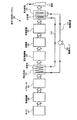
図3は、本実施例に係る熱交換器が適用される排ガス処理システムの概略図である。 FIG. 3 is a schematic diagram of an exhaust gas treatment system to which the heat exchanger according to the present embodiment is applied.
図3に示すように、排ガス処理システム100は、発電プラントや工場などのボイラ101から排出される排ガスが煙突111から放出される過程で、当該排ガスに含まれる窒素酸化物(NOx)、煤塵、および硫黄酸化物(SOx)を除去するものである。
As shown in FIG. 3, the exhaust
先ず、ボイラ101から排出された排ガスG0は、触媒が充填された脱硝装置102に導入される。脱硝装置102において、還元剤として注入されるアンモニア(NH3)により、排ガスG0に含まれる窒素酸化物が水と窒素とに還元され無害化される。
First, the exhaust gas G 0 discharged from the
脱硝装置102から排出された排ガスG1は、エアヒータ(AH)103を経由し、一般に130℃〜150℃の温度に冷却される。
The exhaust gas G 1 discharged from the
エアヒータ103を経た排ガスG2は、ガスガスヒータの熱交換器である熱交換器104に導入され、熱媒体(例えば水など)と熱交換を行うことにより、熱回収される。熱交換器104を経た排ガスG3の温度は、概略85〜110℃となり例えば電気集塵機(EP)105での集塵能力が向上される。
The exhaust gas G 2 that has passed through the air heater 103 is introduced into a
熱交換器104を経た排ガスG3は、電気集塵機105に導入され煤塵が除去される。
The exhaust gas G 3 that has passed through the
電気集塵機105を経た排ガスG4は、電動機により駆動される送風機106により昇圧される。なお、この送風機106は、設けない場合もあるし、ガスガスヒータ再加熱器の後流G7に配置される場合もある。
The exhaust gas G 4 passing through the
送風機106により昇圧された排ガスG5は、脱硫装置107に導入される。脱硫装置107では、石灰石をスラリー状に溶かし込んだ吸収液により、排ガスG5中の硫黄酸化物が吸収除去され、副生成物として石膏(図示せず)が生成される。そして、脱硫装置107を経た排ガスG6の温度は、一般に約50℃程に低下する。
The exhaust gas G 5 whose pressure has been increased by the
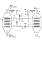
図4は、排ガス処理設備の熱交換器の概略図である。図4に示すように、脱硫装置107を経た排ガスG6は、ガスガスヒータの熱交換器である再加熱部108に導入される。再加熱部108は、上記熱回収部104との間で熱媒体83を循環ポンプ109により一対の循環配管110を往来して循環する過程で、熱回収部104により回収された回収熱により排ガスG6を加熱する。ここで50℃程度の脱硫装置107の出口排ガスG6の温度は、再加熱部108で約85〜110℃に再加熱され、煙突111から大気放出される。
FIG. 4 is a schematic view of a heat exchanger of the exhaust gas treatment facility. As shown in FIG. 4, the exhaust gas G 6 that has passed through the
図4に示すように、排ガスG2が導入され、熱媒体83と熱交換する熱交換器が設けられている。
熱交換器は、熱回収器104と再加熱器108とを熱媒体83が循環するための熱媒体循環通路110を有する。熱媒体83は、熱媒体循環通路110を介して熱回収器104と再加熱器108との間を循環している。熱回収器104と再加熱器108との各々の内部に設けられる熱媒体循環通路110の表面には、複数のフィンがフィンチューブ11に設けられている。熱媒体循環通路110には熱交換部86が設けられ、熱媒体83が循環する際に放熱で奪われた降温相当のエネルギーをスチーム87で加熱することで補い、熱媒体83の媒体温度を維持調整することができる。
As shown in FIG. 4, a heat exchanger that introduces exhaust gas G 2 and exchanges heat with the
The heat exchanger has a heat
熱媒体83は、熱媒体タンク88から熱媒体循環通路110に供給される。熱媒体83は、熱媒体送給ポンプ109により熱媒体循環通路110内を循環させる。また、脱硫装置107からの浄化ガスG6のガス温度に応じて調節弁V1によりスチーム87の供給量を調整し、熱回収器104から排出される排ガスG3のガス温度に応じて調節弁V2により再加熱器108に送給される熱媒体83を熱回収器104に供給し、再加熱器108に送給される熱媒体83の供給量を調整する。なお、再加熱器104から排出される浄化ガスG7は煙突111から外部に排出される。
The
以下、本実施例に係る前記熱回収器の漏洩検査方法について説明する。図1−1及び図1−2は、熱交換器の概略図である。 Hereinafter, the leakage inspection method for the heat recovery device according to the present embodiment will be described. FIGS. 1-1 and 1-2 are schematic views of the heat exchanger.
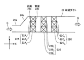
図1−1及び図1−2に示すように、熱交換器は、伝熱管バンドル収納ダクト20内に、伝熱管バンドルを束ねた集合体である伝熱管バンドルを複数配置しており、排ガスの流入方向上流側から低温バンドル22A、中温バンドル22B、低温バンドル22Cとしている。
そして、排ガスのガス流れ方向に熱回収又は熱交換用の複数の伝熱管バンドル群22A(22A1〜22A3)、22B(22B1〜22B3)、22C(22C1〜22C3)を所定間を持って配置している。図1中、符号Gは排ガス、20aはダクト入口部、20bは拡張部を図示する。なお、伝熱管バンドルの排ガス導入方向上流側が正面22aであり、排ガス導入方向下流側が背面22bである。
図中、X方向は排ガス流れ方向であり、Y方向は伝熱管バンドルの挿入方向であり、Z方向は伝熱管バンドルの積み上げ設置方向である。
As shown in FIGS. 1-1 and 1-2, the heat exchanger arranges a plurality of heat transfer tube bundles that are aggregates of heat transfer tube bundles in the heat transfer tube bundle housing duct 20, A
A plurality of heat transfer
In the figure, the X direction is the exhaust gas flow direction, the Y direction is the insertion direction of the heat transfer tube bundle, and the Z direction is the stacked installation direction of the heat transfer tube bundle.
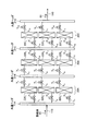
図2は、実施例1に係る熱交換器の配管の構成図である。
図2では、熱交換器に格納される伝熱管バンドルを束ねた集合体である伝熱管バンドルを複数配置して、排ガスの流入方向上流側から高温バンドル20A、中温バンドル20B、低温バンドル20Cとしている。
FIG. 2 is a configuration diagram of piping of the heat exchanger according to the first embodiment.
In FIG. 2, a plurality of heat transfer tube bundles, which are aggregates of heat transfer tube bundles stored in the heat exchanger, are arranged to form a
そして、排ガスのガス流れ方向に熱回収又は熱交換用の複数の伝熱管バンドル(高温用伝熱管バンドル22A(22A1〜22A3)、中温用伝熱管バンドル22B(22B1〜22B3)、低音用伝熱管バンドル22C(22C1〜22C3)を所定間に隔配している。
And in the gas flow direction of the exhaust gas, a plurality of heat transfer tube bundles for heat recovery or heat exchange (high temperature heat
各伝熱管バンドル22A、22B、22Cの前後には、伝熱管バンドルを構成する各伝熱管バンドル22A1〜22A3・・・に熱媒体83を分配する共通熱媒体用ヘッダ21A、21B、21C、21Dが設けられている。
また、共通熱媒体用ヘッダ21A、21B、21C、21Dと各伝熱管バンドル22A1〜22A3・・・とを熱媒ラインL1〜L18により連結している。
熱媒ラインL1〜L18には、各伝熱管バンドル22A1〜22A3・・・へ熱媒体83を供給又は停止する電磁弁V1〜V18を備えている。
Before and after each heat
Further, the common
The heat medium lines L 1 to L 18 are provided with electromagnetic valves V 1 to V 18 for supplying or stopping the
また、熱媒体の漏洩の際、前記電磁弁を操作して特定の伝熱管バンドルへの熱媒体の流入を停止する制御を行う制御手段が設けられている。 Further, when the heat medium leaks, there is provided control means for controlling the operation of the electromagnetic valve to stop the flow of the heat medium into the specific heat transfer tube bundle.
漏洩検査を実施するには、先ず特定の伝熱管バンドル(22A1)への熱媒体の流入を停止し、特定の伝熱管バンドル(22A1)以外の残りの伝熱管バンドルでの運転を継続する。そして運転状態が定常になったことを確認し、熱媒体を供給する熱媒タンクの液面変化を確認する。 To implement the leakage test, first the flow of the heat medium to a particular heat transfer tube bundles (22A 1) is stopped, continued operation of the remaining heat transfer tube bundles other than the specific heat transfer tube bundles (22A 1) . And it confirms that the driving | running state became steady, and confirms the liquid level change of the heat-medium tank which supplies a heat medium.
そして、液面変化の有無により漏れの検査を行う。検査中に例えば排ガス温度が変化する事により熱媒温度も変化する場合があり、このとき熱媒漏洩がなくとも密度変化して液面が変動するため、密度補正計算を行う事によって液面変動の有無を判断する必要がある。これに鑑み、該熱媒タンクの熱媒温度から密度補正演算を自動で行う機能を備える事で液レベルの低下の有無を迅速に発見できる。 Then, a leak is inspected depending on whether or not the liquid level has changed. During the inspection, for example, the heat medium temperature may change due to a change in the exhaust gas temperature. At this time, even if there is no leakage of the heat medium, the density changes and the liquid level fluctuates. It is necessary to judge whether or not there is. In view of this, it is possible to quickly find out whether or not the liquid level has decreased by providing a function of automatically performing density correction calculation from the heat medium temperature of the heat medium tank.
このように、熱媒体の漏れの検査における液面変化は、停止した際の循環している熱媒体の温度変化を考慮し、所定時間ごとに毎回熱媒体の密度を補正し、補正した熱媒体の密度で液面変化を判断することで適正な判断を行うことができる。 As described above, the change in the liquid level in the inspection of the leakage of the heat medium takes into account the temperature change of the circulating heat medium at the time of stoppage, corrects the density of the heat medium every predetermined time, and corrects the heat medium. It is possible to make an appropriate judgment by judging the change in the liquid level based on the density.
すなわち、熱媒体の漏れの検査を行う場合、先ず液レベルを計測すると共に、停止した際の循環している熱媒体の温度を計測する。この温度計測結果から、熱媒体の密度を補正し、検査中における熱媒タンクの熱媒温度から熱媒の密度補正を自動に演算し、熱媒タンク液レベルの低下の有無を迅速に発見する事を可能とする。
この判断を自動で行う際には、例えば5〜10分ごとに温度変化を判断して、密度補正を毎回行うようにすればよい。
That is, when the inspection of the leakage of the heat medium is performed, the liquid level is first measured, and the temperature of the circulating heat medium when stopped is measured. From this temperature measurement result, the density of the heat medium is corrected, the heat medium density correction is automatically calculated from the heat medium temperature of the heat medium tank during inspection, and the presence or absence of a decrease in the heat medium tank liquid level is quickly found. Make things possible.
When this determination is performed automatically, for example, a temperature change may be determined every 5 to 10 minutes, and density correction may be performed every time.
この検査は、熱媒ラインL1〜L18に設けた電磁弁V1〜V18を操作するだけで良いので、作業員が不要となると共に、遠隔監視による漏洩検査が可能となる。 In this inspection, it is only necessary to operate the solenoid valves V 1 to V 18 provided in the heat medium lines L 1 to L 18 , so that an operator is unnecessary and a leak inspection by remote monitoring is possible.
漏洩の有無の検査の具体的な内容について説明する。
前記漏れの検査は、特定の伝熱管バンドル(例えば22A1)への熱媒体の流入を停止しても、液面変化がある場合には、熱媒体の流入を停止した伝熱管バンドル(22A1)の異常が無いと判断し、他の伝熱管バンドルの検査を行う。
すなわち、伝熱管バンドル(22A1)への熱媒体の流入を停止しても、未だ液面変化があるということは、熱媒体の流入を停止した伝熱管バンドル(22A1)は正常であると判定できる。
The specific contents of the inspection for the presence or absence of leakage will be described.
In the inspection of the leakage, when the flow of the heat medium into a specific heat transfer tube bundle (for example, 22A 1 ) is stopped, but there is a change in the liquid level, the heat transfer tube bundle (22A 1 that has stopped the flow of the heat medium). ) And inspect other heat transfer tube bundles.
That is, even if the flow of the heat medium into the heat transfer tube bundle (22A 1 ) is stopped, the liquid level is still changed, which means that the heat transfer tube bundle (22A 1 ) that stopped the flow of the heat medium is normal. Can be judged.
前記漏れの検査は、特定の伝熱管バンドル(22A1)への熱媒体の流入を停止し、液面変化が無い場合には、熱媒体の流入を停止した伝熱管バンドルに異常があると判断する。そして、熱媒体の流入を停止した伝熱管バンドル(22A1)に異常があると判定できる。 The inspection of the leakage stops the inflow of the heat medium into the specific heat transfer tube bundle (22A 1 ), and if there is no change in the liquid level, it is determined that there is an abnormality in the heat transfer tube bundle that stopped the inflow of the heat medium. To do. Then, it can be determined that there is an abnormality in the heat transfer tube bundle (22A 1 ) that stopped the inflow of the heat medium.
また、検査は、同時に2以上の伝熱管バンドルに対して実施するようにしてもよい。
すなわち、特定のバンドルへの熱媒体の流入の停止を、少なくとも1つ以上とし、同時に複数のバンドルへの熱媒体の流入を停止し、漏洩の検査を行うようにしてもよい。
In addition, the inspection may be performed on two or more heat transfer tube bundles at the same time.
That is, at least one stop of the inflow of the heat medium into the specific bundle may be performed, and at the same time, the inflow of the heat medium into the plurality of bundles may be stopped to check for leakage.
このように、各バンドルの入出口に電磁弁を設け、共通熱媒用ヘッダを設けることにより各バンドルのバイパスが可能となると共に、各電磁弁を例えば遠隔監視により実施することができ、熱媒タンクの液レベル検知と連動させることで、漏洩箇所の検知を迅速に把握することが可能となる。 In this way, by providing an electromagnetic valve at the inlet / outlet of each bundle and providing a common heat medium header, each bundle can be bypassed, and each electromagnetic valve can be implemented by remote monitoring, for example. By interlocking with the liquid level detection of the tank, it becomes possible to quickly grasp the detection of the leaked portion.
従来は、熱媒漏洩箇所が特定されると、検査時間を要するので、熱媒漏洩が確認された他の複数のバンドルでの熱媒漏洩調査を継続して行う事が困難であったが、本発明によれば、電磁弁の開閉操作を行うことでよいので、全ての伝熱管バンドルへの漏洩検査を実施することが可能となる。又、本発明により複数バンドルでの熱媒漏洩調査も同時に行えるようになるため、熱媒漏洩が疑われる全てのバンドルを一度にバイパスする事で補修を要するバンドル箇所の組合せの最終確認を行う事も可能となる。
また、この漏洩検査は遠隔による監視が可能となるので、複数のボイラ設備を監視するネットワークを構築して集中監視することもできる。
Conventionally, since the inspection time is required when the heat medium leak location is specified, it was difficult to continue the heat medium leak investigation in other bundles in which the heat medium leak was confirmed. According to the present invention, it is only necessary to open and close the solenoid valve, so that it is possible to perform a leak test on all heat transfer tube bundles. In addition, since the present invention enables a plurality of bundles to investigate heat medium leakage at the same time, it is possible to perform final confirmation of the combination of bundle parts requiring repair by bypassing all bundles that are suspected of heat medium leakage at a time. Is also possible.
In addition, since this leakage inspection can be remotely monitored, a network for monitoring a plurality of boiler facilities can be constructed to perform centralized monitoring.
なお、本発明では、漏洩の検知を熱媒タンクでの液面の水位の変化により確認しているが、本発明はこれに限定されず、例えば、熱媒漏洩した場合はガスガスヒータ熱回収器、再加熱器の排ガス圧損が上昇するためこれを監視するようにしてもよい。 In the present invention, the detection of leakage is confirmed by the change in the water level of the liquid level in the heat medium tank, but the present invention is not limited to this. For example, when the heat medium leaks, the gas gas heater heat recovery device Since the exhaust gas pressure loss of the reheater increases, this may be monitored.
21A〜21D 共通熱媒体用ヘッダ
22A〜22C 伝熱管バンドル
83 熱媒体
V1〜V18 電磁弁
L1〜L18 熱媒ライン
Header for 21A~21D
Claims (5)
各伝熱管バンドルの前後に設けられ、伝熱管バンドルを構成する各伝熱管バンドルに熱媒体を分配する共通熱媒体用ヘッダと、
前記共通熱媒体用ヘッダと各伝熱管バンドルとを連結すると共に、各伝熱管バンドルへ熱媒体を供給又は停止する電磁弁を備えた熱媒ラインと、
熱媒体の漏洩の際、前記電磁弁を操作して特定の伝熱管バンドルへの熱媒体の流入を停止する制御を行う制御手段とを具備し、
特定の伝熱管バンドルへの熱媒体の流入を停止し、残りの伝熱管バンドルでの運転状態が定常になったことを確認し、熱媒体を供給する熱媒タンクの液面変化を確認し、熱媒体の漏れの検査を行うことを特徴とする熱交換器の漏洩検査方法。 In the leak inspection method of the heat exchanger in which a plurality of heat transfer tube bundles for heat recovery or heat exchange are arranged at predetermined intervals in the gas flow direction of the exhaust gas,
A header for a common heat medium that is provided before and after each heat transfer tube bundle and distributes the heat medium to each heat transfer tube bundle constituting the heat transfer tube bundle;
While connecting the header for common heat medium and each heat transfer tube bundle, a heat medium line provided with an electromagnetic valve for supplying or stopping the heat medium to each heat transfer tube bundle,
A control means for controlling the operation of stopping the inflow of the heat medium into the specific heat transfer tube bundle by operating the electromagnetic valve when the heat medium leaks,
Stop the inflow of the heat medium to a specific heat transfer tube bundle, confirm that the operation state in the remaining heat transfer tube bundle has become steady, check the liquid level change of the heat medium tank that supplies the heat medium, A heat exchanger leakage inspection method characterized by performing a heat medium leakage inspection.
前記熱媒体の漏れの検査は、特定の伝熱管バンドルへの熱媒体の流入を停止しても、熱媒体の液面変化がある場合には、熱媒体の流入を停止した伝熱管バンドルの異常が無いと判断し、他の伝熱管バンドルの検査を行うことを特徴とする熱交換器の漏洩検査方法。 In claim 1,
The inspection of the leakage of the heat transfer medium is performed by checking the abnormality of the heat transfer tube bundle that stopped the inflow of the heat medium when there is a change in the liquid level of the heat medium even if the flow of the heat medium to the specific heat transfer pipe bundle is stopped. A leakage inspection method for a heat exchanger, characterized in that the heat exchanger tube bundle is inspected and the other heat transfer tube bundle is inspected.
前記熱媒体の漏れの検査は、特定の伝熱管バンドルへの熱媒体の流入を停止し、液面変化が無い場合には、熱媒体の流入を停止した伝熱管バンドルに異常があると判断することを特徴とする熱交換器の漏洩検査方法。 In claim 1,
The inspection of the leakage of the heat medium stops the inflow of the heat medium into the specific heat transfer tube bundle, and if there is no change in the liquid level, it is determined that there is an abnormality in the heat transfer tube bundle that stopped the inflow of the heat medium. A leakage inspection method for a heat exchanger.
前記熱媒体の漏れの検査の液面変化は、熱媒体の流入を停止した際に循環している熱媒体の温度変化を考慮し、所定時間ごとに毎回熱媒体の密度を補正し、補正した熱媒体の密度をもとに液面変化を判断することを特徴とする熱交換器の漏洩検査方法。 In claim 2 or 3,
The liquid level change in the inspection of the leakage of the heat medium is corrected by correcting the density of the heat medium every predetermined time in consideration of the temperature change of the circulating heat medium when the inflow of the heat medium is stopped. A leakage inspection method for a heat exchanger, wherein a change in liquid level is determined based on a density of a heat medium.
特定の伝熱管バンドルへの熱媒体の流入の停止を、少なくとも1つ以上とすることを特徴とする熱交換器の漏洩検査方法。 In any one of Claims 1 thru | or 4,
A leakage inspection method for a heat exchanger, characterized in that at least one or more stops the inflow of the heat medium into the specific heat transfer tube bundle.
Priority Applications (4)
| Application Number | Priority Date | Filing Date | Title |
|---|---|---|---|
| JP2011043315A JP2012181069A (en) | 2011-02-28 | 2011-02-28 | Leak inspection method for heat exchanger |
| US14/001,432 US9714882B2 (en) | 2011-02-28 | 2011-11-10 | Leakage inspection method of heat exchanger |
| EP11859868.9A EP2682728A4 (en) | 2011-02-28 | 2011-11-10 | Method for inspecting leakage of heat exchanger |
| PCT/JP2011/075981 WO2012117620A1 (en) | 2011-02-28 | 2011-11-10 | Method for inspecting leakage of heat exchanger |
Applications Claiming Priority (1)
| Application Number | Priority Date | Filing Date | Title |
|---|---|---|---|
| JP2011043315A JP2012181069A (en) | 2011-02-28 | 2011-02-28 | Leak inspection method for heat exchanger |
Publications (1)
| Publication Number | Publication Date |
|---|---|
| JP2012181069A true JP2012181069A (en) | 2012-09-20 |
Family
ID=46757569
Family Applications (1)
| Application Number | Title | Priority Date | Filing Date |
|---|---|---|---|
| JP2011043315A Pending JP2012181069A (en) | 2011-02-28 | 2011-02-28 | Leak inspection method for heat exchanger |
Country Status (4)
| Country | Link |
|---|---|
| US (1) | US9714882B2 (en) |
| EP (1) | EP2682728A4 (en) |
| JP (1) | JP2012181069A (en) |
| WO (1) | WO2012117620A1 (en) |
Cited By (1)
| Publication number | Priority date | Publication date | Assignee | Title |
|---|---|---|---|---|
| KR20170102515A (en) * | 2015-02-05 | 2017-09-11 | 미츠비시 히타치 파워 시스템즈 가부시키가이샤 | Heat exchanger and method for controlling heat exchanger |
Families Citing this family (3)
| Publication number | Priority date | Publication date | Assignee | Title |
|---|---|---|---|---|
| CN103759894B (en) * | 2014-01-08 | 2016-05-04 | 中国石油大学(北京) | A kind of detection method of heat exchanger leakage current and system |
| CN107621334B (en) * | 2016-07-15 | 2019-09-17 | 核工业西南物理研究院 | For hot helium leak test gas heating circulation system and quickly heat cooling means |
| CN113218587A (en) * | 2021-03-16 | 2021-08-06 | 大唐七台河发电有限责任公司 | Leakage detection combined device and leakage detection method for pressure vessel tube bundle of electrician enterprise |
Citations (2)
| Publication number | Priority date | Publication date | Assignee | Title |
|---|---|---|---|---|
| JPH11304138A (en) * | 1998-04-21 | 1999-11-05 | Mitsubishi Heavy Ind Ltd | Gas/gas heater |
| JP2009222569A (en) * | 2008-03-17 | 2009-10-01 | Ihi Corp | Heating medium leakage inspection device and heating medium leakage inspection method of heat exchanger |
Family Cites Families (8)
| Publication number | Priority date | Publication date | Assignee | Title |
|---|---|---|---|---|
| US3992894A (en) * | 1975-12-22 | 1976-11-23 | International Business Machines Corporation | Inter-active dual loop cooling system |
| JPS625152A (en) | 1985-07-02 | 1987-01-12 | Mitsubishi Heavy Ind Ltd | Monitoring of corrosion |
| US4738304A (en) * | 1986-03-12 | 1988-04-19 | Rca Corporation | Direct condensation radiator for spacecraft |
| JP3643241B2 (en) | 1998-08-07 | 2005-04-27 | バブコック日立株式会社 | Leakage position detection device |
| US7270174B2 (en) * | 2003-12-16 | 2007-09-18 | International Business Machines Corporation | Method, system and program product for automatically checking coolant loops of a cooling system for a computing environment |
| EP1811282A1 (en) | 2006-01-20 | 2007-07-25 | ABB Technology AG | Monitoring a degradation of steam generator boiler tubes |
| JP5186951B2 (en) * | 2008-02-29 | 2013-04-24 | ダイキン工業株式会社 | Air conditioner |
| JP4838870B2 (en) | 2009-04-28 | 2011-12-14 | 三菱重工業株式会社 | Heat transfer tube monitoring device |
-
2011
- 2011-02-28 JP JP2011043315A patent/JP2012181069A/en active Pending
- 2011-11-10 US US14/001,432 patent/US9714882B2/en active Active
- 2011-11-10 EP EP11859868.9A patent/EP2682728A4/en not_active Withdrawn
- 2011-11-10 WO PCT/JP2011/075981 patent/WO2012117620A1/en active Application Filing
Patent Citations (2)
| Publication number | Priority date | Publication date | Assignee | Title |
|---|---|---|---|---|
| JPH11304138A (en) * | 1998-04-21 | 1999-11-05 | Mitsubishi Heavy Ind Ltd | Gas/gas heater |
| JP2009222569A (en) * | 2008-03-17 | 2009-10-01 | Ihi Corp | Heating medium leakage inspection device and heating medium leakage inspection method of heat exchanger |
Cited By (5)
| Publication number | Priority date | Publication date | Assignee | Title |
|---|---|---|---|---|
| KR20170102515A (en) * | 2015-02-05 | 2017-09-11 | 미츠비시 히타치 파워 시스템즈 가부시키가이샤 | Heat exchanger and method for controlling heat exchanger |
| CN107208888A (en) * | 2015-02-05 | 2017-09-26 | 三菱日立电力系统株式会社 | The control method of heat exchanger and heat exchanger |
| KR101892887B1 (en) * | 2015-02-05 | 2018-10-04 | 미츠비시 히타치 파워 시스템즈 가부시키가이샤 | Heat exchanger and method for controlling heat exchanger |
| US10436096B2 (en) | 2015-02-05 | 2019-10-08 | Mitsubishi Hitachi Power Systems, Ltd. | Heat exchanger and method for controlling heat exchanger |
| CN107208888B (en) * | 2015-02-05 | 2022-01-07 | 三菱动力株式会社 | Heat exchanger and method for controlling heat exchanger |
Also Published As
| Publication number | Publication date |
|---|---|
| WO2012117620A1 (en) | 2012-09-07 |
| US20130327128A1 (en) | 2013-12-12 |
| EP2682728A4 (en) | 2016-07-13 |
| EP2682728A1 (en) | 2014-01-08 |
| US9714882B2 (en) | 2017-07-25 |
Similar Documents
| Publication | Publication Date | Title |
|---|---|---|
| TWI407058B (en) | Heat transfer tube monitoring apparatus | |
| JP5773708B2 (en) | Heat exchanger and method for estimating remaining life of heat exchanger | |
| WO2012117620A1 (en) | Method for inspecting leakage of heat exchanger | |
| EP2682677B1 (en) | Heat exchanger | |
| JP2012215335A5 (en) | ||
| WO2017169310A1 (en) | Exhaust-gas treatment system | |
| CN107208888B (en) | Heat exchanger and method for controlling heat exchanger | |
| JP5410209B2 (en) | Leakage detection method and apparatus for gas gas heat exchanger | |
| JP2012180958A5 (en) | ||
| JP7221158B2 (en) | Heat exchanger, flue gas treatment device, and heat exchanger replacement method | |
| JP2009222569A (en) | Heating medium leakage inspection device and heating medium leakage inspection method of heat exchanger | |
| CN204730235U (en) | A kind of high-pressure water flushing device for air preheater, air preheating system | |
| CN204026645U (en) | A kind of anti-leak economizer | |
| JP2015038422A (en) | Heat exchanger and method of estimating residual life of heat exchanger | |
| JP2012057860A (en) | Exhaust heat recovery device | |
| JP5268561B2 (en) | Daily combustion management method in oil fired boiler facilities | |
| CN203880733U (en) | Flue gas heat treatment equipment | |
| JP6244606B2 (en) | Heat exchanger repair method | |
| KR100747739B1 (en) | Gas cooler vibration reduction structure of boiler desulfurization equipment | |
| JP2012058182A (en) | Wear amount management method for fire-resistant material layer | |
| JP7147486B2 (en) | Leak determination method for tubular heat exchangers | |
| JP2016017716A (en) | Exhaust heat recovery system and exhaust heat recovery system maintenance method | |
| CN103994459A (en) | Flue gas heating treatment device | |
| JP2018132280A (en) | Boiler and operation method thereof | |
| JP2022052283A (en) | Heat exchanger and flue gas treatment device |
Legal Events
| Date | Code | Title | Description |
|---|---|---|---|
| A621 | Written request for application examination |
Free format text: JAPANESE INTERMEDIATE CODE: A621 Effective date: 20130813 |
|
| A131 | Notification of reasons for refusal |
Free format text: JAPANESE INTERMEDIATE CODE: A131 Effective date: 20141007 |
|
| A02 | Decision of refusal |
Free format text: JAPANESE INTERMEDIATE CODE: A02 Effective date: 20150407 |