EP3255122A1 - Ferrocoke manufacturing method - Google Patents
Ferrocoke manufacturing method Download PDFInfo
- Publication number
- EP3255122A1 EP3255122A1 EP16746558.2A EP16746558A EP3255122A1 EP 3255122 A1 EP3255122 A1 EP 3255122A1 EP 16746558 A EP16746558 A EP 16746558A EP 3255122 A1 EP3255122 A1 EP 3255122A1
- Authority
- EP
- European Patent Office
- Prior art keywords
- coal
- csn
- softening
- hardly
- softening coal
- Prior art date
- Legal status (The legal status is an assumption and is not a legal conclusion. Google has not performed a legal analysis and makes no representation as to the accuracy of the status listed.)
- Granted
Links
Images


Classifications
-
- C—CHEMISTRY; METALLURGY
- C22—METALLURGY; FERROUS OR NON-FERROUS ALLOYS; TREATMENT OF ALLOYS OR NON-FERROUS METALS
- C22B—PRODUCTION AND REFINING OF METALS; PRETREATMENT OF RAW MATERIALS
- C22B1/00—Preliminary treatment of ores or scrap
- C22B1/14—Agglomerating; Briquetting; Binding; Granulating
- C22B1/24—Binding; Briquetting ; Granulating
- C22B1/242—Binding; Briquetting ; Granulating with binders
-
- C—CHEMISTRY; METALLURGY
- C10—PETROLEUM, GAS OR COKE INDUSTRIES; TECHNICAL GASES CONTAINING CARBON MONOXIDE; FUELS; LUBRICANTS; PEAT
- C10B—DESTRUCTIVE DISTILLATION OF CARBONACEOUS MATERIALS FOR PRODUCTION OF GAS, COKE, TAR, OR SIMILAR MATERIALS
- C10B1/00—Retorts
- C10B1/02—Stationary retorts
- C10B1/04—Vertical retorts
-
- C—CHEMISTRY; METALLURGY
- C10—PETROLEUM, GAS OR COKE INDUSTRIES; TECHNICAL GASES CONTAINING CARBON MONOXIDE; FUELS; LUBRICANTS; PEAT
- C10B—DESTRUCTIVE DISTILLATION OF CARBONACEOUS MATERIALS FOR PRODUCTION OF GAS, COKE, TAR, OR SIMILAR MATERIALS
- C10B31/00—Charging devices
- C10B31/02—Charging devices for charging vertically
-
- C—CHEMISTRY; METALLURGY
- C10—PETROLEUM, GAS OR COKE INDUSTRIES; TECHNICAL GASES CONTAINING CARBON MONOXIDE; FUELS; LUBRICANTS; PEAT
- C10B—DESTRUCTIVE DISTILLATION OF CARBONACEOUS MATERIALS FOR PRODUCTION OF GAS, COKE, TAR, OR SIMILAR MATERIALS
- C10B45/00—Other details
-
- C—CHEMISTRY; METALLURGY
- C10—PETROLEUM, GAS OR COKE INDUSTRIES; TECHNICAL GASES CONTAINING CARBON MONOXIDE; FUELS; LUBRICANTS; PEAT
- C10B—DESTRUCTIVE DISTILLATION OF CARBONACEOUS MATERIALS FOR PRODUCTION OF GAS, COKE, TAR, OR SIMILAR MATERIALS
- C10B53/00—Destructive distillation, specially adapted for particular solid raw materials or solid raw materials in special form
- C10B53/08—Destructive distillation, specially adapted for particular solid raw materials or solid raw materials in special form in the form of briquettes, lumps and the like
-
- C—CHEMISTRY; METALLURGY
- C10—PETROLEUM, GAS OR COKE INDUSTRIES; TECHNICAL GASES CONTAINING CARBON MONOXIDE; FUELS; LUBRICANTS; PEAT
- C10B—DESTRUCTIVE DISTILLATION OF CARBONACEOUS MATERIALS FOR PRODUCTION OF GAS, COKE, TAR, OR SIMILAR MATERIALS
- C10B57/00—Other carbonising or coking processes; Features of destructive distillation processes in general
- C10B57/04—Other carbonising or coking processes; Features of destructive distillation processes in general using charges of special composition
-
- C—CHEMISTRY; METALLURGY
- C10—PETROLEUM, GAS OR COKE INDUSTRIES; TECHNICAL GASES CONTAINING CARBON MONOXIDE; FUELS; LUBRICANTS; PEAT
- C10B—DESTRUCTIVE DISTILLATION OF CARBONACEOUS MATERIALS FOR PRODUCTION OF GAS, COKE, TAR, OR SIMILAR MATERIALS
- C10B57/00—Other carbonising or coking processes; Features of destructive distillation processes in general
- C10B57/04—Other carbonising or coking processes; Features of destructive distillation processes in general using charges of special composition
- C10B57/06—Other carbonising or coking processes; Features of destructive distillation processes in general using charges of special composition containing additives
-
- C—CHEMISTRY; METALLURGY
- C10—PETROLEUM, GAS OR COKE INDUSTRIES; TECHNICAL GASES CONTAINING CARBON MONOXIDE; FUELS; LUBRICANTS; PEAT
- C10L—FUELS NOT OTHERWISE PROVIDED FOR; NATURAL GAS; SYNTHETIC NATURAL GAS OBTAINED BY PROCESSES NOT COVERED BY SUBCLASSES C10G OR C10K; LIQUIFIED PETROLEUM GAS; USE OF ADDITIVES TO FUELS OR FIRES; FIRE-LIGHTERS
- C10L5/00—Solid fuels
- C10L5/02—Solid fuels such as briquettes consisting mainly of carbonaceous materials of mineral or non-mineral origin
- C10L5/04—Raw material of mineral origin to be used; Pretreatment thereof
-
- C—CHEMISTRY; METALLURGY
- C10—PETROLEUM, GAS OR COKE INDUSTRIES; TECHNICAL GASES CONTAINING CARBON MONOXIDE; FUELS; LUBRICANTS; PEAT
- C10L—FUELS NOT OTHERWISE PROVIDED FOR; NATURAL GAS; SYNTHETIC NATURAL GAS OBTAINED BY PROCESSES NOT COVERED BY SUBCLASSES C10G OR C10K; LIQUIFIED PETROLEUM GAS; USE OF ADDITIVES TO FUELS OR FIRES; FIRE-LIGHTERS
- C10L5/00—Solid fuels
- C10L5/02—Solid fuels such as briquettes consisting mainly of carbonaceous materials of mineral or non-mineral origin
- C10L5/06—Methods of shaping, e.g. pelletizing or briquetting
-
- C—CHEMISTRY; METALLURGY
- C21—METALLURGY OF IRON
- C21B—MANUFACTURE OF IRON OR STEEL
- C21B13/00—Making spongy iron or liquid steel, by direct processes
- C21B13/0066—Preliminary conditioning of the solid carbonaceous reductant
-
- C—CHEMISTRY; METALLURGY
- C21—METALLURGY OF IRON
- C21B—MANUFACTURE OF IRON OR STEEL
- C21B5/00—Making pig-iron in the blast furnace
- C21B5/007—Conditions of the cokes or characterised by the cokes used
-
- C—CHEMISTRY; METALLURGY
- C10—PETROLEUM, GAS OR COKE INDUSTRIES; TECHNICAL GASES CONTAINING CARBON MONOXIDE; FUELS; LUBRICANTS; PEAT
- C10L—FUELS NOT OTHERWISE PROVIDED FOR; NATURAL GAS; SYNTHETIC NATURAL GAS OBTAINED BY PROCESSES NOT COVERED BY SUBCLASSES C10G OR C10K; LIQUIFIED PETROLEUM GAS; USE OF ADDITIVES TO FUELS OR FIRES; FIRE-LIGHTERS
- C10L2200/00—Components of fuel compositions
- C10L2200/02—Inorganic or organic compounds containing atoms other than C, H or O, e.g. organic compounds containing heteroatoms or metal organic complexes
- C10L2200/0204—Metals or alloys
- C10L2200/024—Group VIII metals: Fe, Co, Ni, Ru, Rh, Pd, Os, Ir, Pt
-
- C—CHEMISTRY; METALLURGY
- C10—PETROLEUM, GAS OR COKE INDUSTRIES; TECHNICAL GASES CONTAINING CARBON MONOXIDE; FUELS; LUBRICANTS; PEAT
- C10L—FUELS NOT OTHERWISE PROVIDED FOR; NATURAL GAS; SYNTHETIC NATURAL GAS OBTAINED BY PROCESSES NOT COVERED BY SUBCLASSES C10G OR C10K; LIQUIFIED PETROLEUM GAS; USE OF ADDITIVES TO FUELS OR FIRES; FIRE-LIGHTERS
- C10L2290/00—Fuel preparation or upgrading, processes or apparatus therefore, comprising specific process steps or apparatus units
- C10L2290/30—Pressing, compressing or compacting
Definitions
- This invention relates to a ferrocoke manufacturing method by carbonizing a mixture of coal and iron ore.
- the ferrocoke is usually manufactured by using an easily softening coal (caking coal, strong caking coal) indicating a softening and melting property during carbonization of coal and/or a hardly softening coal (non-slightly caking coal, non-caking coal) suppressing fusion between mutual shaped bodies.
- the hardly softening coal has a maximum fluidity of less than 2 ddpm measured by Gieseler plastometer described in JIS M8801.
- it is important that ferrocoke has an excellent reactivity, but it is required to have a certain strength because deterioration of gas permeability in the blast furnace is caused if it is easily powdered in the blast furnace.
- a blending ratio of coal to iron ore is frequently made to about 7:3.
- the ratio of iron ore is lower than the above value, the reactivity of ferrocoke tends to be decreased, while when it exceeds the above value, the improvement of the reactivity is small and the strength of ferrocoke tends to be largely decreased.
- a target drum strength of ferrocoke (150 revolutions, 6 mm index) is defined to be not less than 82 in "Research on innovative iron-making process" performed since 2006 by the New Energy and Industrial Technology Development Organization, for example.
- Patent Document 1 discloses a method wherein semi-anthracite having a volatile matter of not more than 18 mass% and/or anthracite are/is blended to perform size control for suppressing fusion of the ferrocoke and maintaining strength.
- Patent Document 2 discloses that a blending ratio of non-caking coal is defined based on a ratio of Fe to O in iron ore in the blending of hardly softening coal (non-caking coal or coal having no caking property described in Patent Document 2).
- Patent Document 3 discloses that iron sand is used as an iron source and a blending ratio of non-caking coal is determined in accordance with a blending ratio of the iron sand.
- a substance having no caking property or a maximum fluidity of 0 ddpm such as non-caking coal, lignite, anthracite, petroleum coke, coal or the like is used as a raw material.
- the conventional ferrocoke mainly uses coal having no caking property (substance having a maximum fluidity of 0 ddpm such as non-caking coal, lignite, anthracite, petroleum coke, coal) as a raw material.
- coal indicating slight swelling by an evaluation of button index (hereinafter abbreviated as "CSN”) described in JIS M8801 exists in the coals having a maximum fluidity (hereinafter abbreviated as "MF”) of 0 ddpm, so that it is considered that coke further increasing the strength of the ferrocoke is existent in the coals having MF of 0 ddpm.
- CSN means an index of discrete value such as 1, 1.5, 2, .... 9 fitted when a test sample is placed in an exclusive crucible and rapidly heated at 820°C and a form of a coke cake after resolidification is compared to a standard profile diagram. As the index value becomes smaller, the caking property becomes poorer.
- Patent Document 4 As regards the button index (CSN), there is a technique disclosed, for example, in Patent Document 4 as a conventional technique for the manufacture of shaped coke instead of the ferrocoke. In the examples of this document is described a case of blending an inferior quality coal having CSN of 0.5. In Patent Documents 5 and 6 is described a case of blending a non-caking coal or a fine caking coal having CSN of 0-1. In Patent Document 7 is described a case of blending a non-caking coal or a fine caking coal having CSN of 0-1 and a fine caking coal having CSN of 1.5. In the case of blending the fine caking coal having CSN of 1.5, the strength of the shaped coke is low.
- All the raw material for the shaped coke is usually constructed with carbon material.
- the iron ore has no effect of the improvement of ferrocoke, so that it is considered that it is preferable to use coal having MF of more than 0 ddpm and CSN of not less than 0 as a carbon material.
- the blending ratio has hitherto been described as in Patent Documents 2 and 3, but it is actual that there is no finding on the examination of the nature (MF, CSN).
- Ferrocoke is usually manufactured by carbonizing a shaped body of a mixture of a carbon material such as coal and an iron ore as an iron source in an exclusive shaft furnace. Also, the ferrocoke is required to have a high reactivity and a high strength. In order to obtain the high reactivity of the ferrocoke, it is considered to increase blending of an iron ore or an easily softening coal having a low carbon content. However, the increase of blending the iron ore is apt to bring about the decrease of ferrocoke strength, so that it is considered that the use of the easily softening coal having a low carbon content is more preferable because the decrease of the strength becomes smaller.
- the inventors have made various studies on the aforementioned problems inherent to the conventional techniques and found that the ferrocoke strength can be increased by setting the button index of the hardly softening coal as a raw coal material for the manufacture of ferrocoke to a preferable range without causing the fusion between the mutual shaped bodies, and as a result the invention has been accomplished. Furthermore, it has been found that similar results can be obtained by properly adjusting the nature and blending amount of the easily softening coal in accordance with the nature of the hardly softening coal, and it becomes possible to select the raw materials within a wider range.
- the invention is a ferrocoke manufacturing method by shaping and carbonizing a mixture of coal and iron ore, characterized in that a hardly softening coal having a button index (CSN) of not more than 2.0 is used as the coal.
- CSN button index
- ferrocoke having a required strength can be manufactured even when only the hardly softening coal is used, and also it is possible to select coals within a wider range by selecting the easily softening coal in accordance with the nature of the hardly softening coal, and it is possible to manufacture ferrocoke having a higher strength even when a coal having a low carbon content and being low in the cost is used as the easily softening coal. Also, when a coal having a low carbon content can be used by applying the invention, ferrocoke having a higher reactivity can be obtained, which largely contributes to the operation of the blast furnace at a low reducing material ratio.
- the invention is a ferrocoke manufacturing method having a high strength and a high reactivity without causing the decrease of the strength even if an inferior quality coal is used. That is, this method is characterized in that when a mixture of coal and iron ore is shaped and carbonized to manufacture ferrocoke, a coal having a button index (CSN) of not more than 2.0 is used as a hardly softening coal.
- CSN button index
- the reason why the button index (CSN) of the hardly softening coal is limited to not more than 2.0 is due to the fact that when a coal having a CSN value of more than 2.0 is used, if a shaped body of this hardly softening coal and an iron ore (a weight ratio of the iron ore in the mixture of the hardly softening coal and the iron ore is 30 mass%) is carbonized, fusion between the mutual shaped bodies is generated inevitably and hence the effect of suppressing the fusion by the addition of the hardly softening coal cannot be obtained.
- CSN button index
- the lower limit of the button index (CSN) of the hardly softening coal is not particularly limited.
- the button index (CSN) of the hardly softening coal is 1.0, a target strength may not be attained in accordance with a volatile matter of the hardly softening coal as seen from examples mentioned later, so that the button index (CSN) of the hardly softening coal is preferable to be 1.5-2.0.
- the coal is a blend of hardly softening coal and easily softening coal and the hardly softening coal is a coal having a button index (CSN) of 1.5-2.0
- CSN button index
- the easily softening coal satisfies that a value obtained by multiplying CSN of the easily softening coal by a blending ratio thereof in all coals is not more than 5.0.
- the coal is a blend of hardly softening coal and easily softening coal and the hardly softening coal is a coal having a button index (CSN) of 1.0
- the hardly softening coal is a coal having a volatile matter of not less than 17% and the easily softening coal satisfies that a value obtained by multiplying CSN of the easily softening coal by a blending ratio thereof in all coals is within a range of 0.3-5.2.
- the volatile matter is measured according to JIS M8812 and represented by dry ash free base.
- a shaped body is manufactured by changing each CSN of a hardly softening coal and an easily softening coal (carbon content and MF are varied with the change of CSN) to evaluate strength after carbonization (ferrocoke strength).
- the hardly softening coal and the easily softening coal are blended so as to render coals of plural brands into predetermined CSN and carbon content.
- Table 1 shows a grade of the easily softening coal
- Table 2 shows a grade of the hardly softening coal.
- an iron ore are used ones having a total iron content of 57 mass%.
- a pulverized grain size of each of the coal and iron ore is not more than 3 mm in total.
- a maximum fluidity MF in Table 2 is measured by a Gieseler plastometer. A sensitivity is low at a lower range of MF. In this time, MF measurement of the hardly softening coal is performed five times, and an average value thereof is determined as MF value.
- the shaping treatment is performed by the following method. That is, the coal, iron ore and binder are mixed so that blending ratios are set to 65.8 mass%, 28.2 mass% and 6 mass% to the total weight of raw materials, respectively.
- the coal the easily softening coal and the hardly softening coal are blended.
- a mixture of these raw materials is kneaded in a high-speed mixer at 140-160°C for about 2 minutes, and the kneaded material is shaped into briquettes in a double roll type shaping machine.
- a size of the roll is 650 mm in diameter and 104 mm in width, and shaping is performed at a peripheral speed of 0.2 m/s and a linear pressure of 4 t/cm.
- a shaped body has a size of 30 mm x 25 mm x 18 mm (6 cc) and is oval.
- the thus obtained shaped bodies are carbonized according to the following carbonization process of a laboratory scale. That is, 3 kg of the shaped bodies are filled in a carbonization can of 300 mm in both length and 400 mm in height, kept at a furnace wall temperature of 1000°C for 6 hours and then cooled in nitrogen atmosphere. The carbonized material cooled to room temperature is taken out to measure strength and evaluate a fusion ratio. The measurement of the strength is performed as a drum strength (DI 150 6 ).
- DI 150 6 means a value obtained by measuring a mass ratio of coke having a grain size of not less than 6 mm under a condition of 15 rpm, 150 revolutions by a revolution strength testing method of JIS K2151.
- a target strength is set to not less than 82.
- the fusion ratio is evaluated by a weight percentage of a fused material to a total weight of the carbonized material.
- Example 1 preferable CSN and volatile matter of hardly softening coal and nature of easily softening coal in a coal blend>
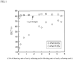
- ferrocoke strength to a value obtained by multiplying CSN of the easily softening coal by a weight ratio of the easily softening coal to the total coal weight is plotted in a graph of FIG. 1 .
- the hardly softening coal is used a coal having CSN of 1.0 and a volatile matter of 13.6% and 17.2%.
- Table 2 describes two kinds of coals having CSN of 1.0 as brands J and K of the hardly softening coal. In the case that the volatile matter is 13.6%, the brands J and K are blended in an each amount of 50 mass%, while in the case that the volatile matter is 17.2%, brands L and M are blended in an each amount of 50 mass%.
- Table 3 shows a blending condition of the easily softening coal blended with the hardly softening coal, value obtained by multiplying CSN of the easily softening coal by a weight ratio of the easily softening coal to the total coal weight, and strength of ferrocoke obtained from a mixed coal blended with a coal having CSN of 1.0 as the hardly softening coal as data in the graph of FIG. 1 .
- ferrocoke contains an iron ore having no compatibility with carbon materials, it is considered that the ferrocoke strength is apt to be largely decreased when being blended with a hardly softening coal hardly fused by softening and showing no swellability.
- the plot having 0 as the value of abscissa axis shows the result in the blending of only hardly softening coals.
- the volatile matter is 13.6%, the strength is largely decreased.
- the volatile matter is 17.2%, the strength is near to the target value in the blending of only the coals.
- the blending ratio of the easily softening coal is 0.1-0.8, the strength exceeds the target value when the value obtained by multiplying CSN of the easily softening coal by the blending weight ratio of the easily softening coal is 0.3-5.2.
- the reason why the optimum range is existent in the value obtained by multiplying CSN of the easily softening coal by the blending weight ratio of the easily softening coal is considered due to the fact that when the value is small, swelling of the coal is small and the adhesion between the grains is deteriorated, while when the value is large, the strength after the carbonization is decreased by increase of porosity associated with the swelling of the carbonized material.
- Hardly softening coals having CSN of 1.5 and 2.0 are examined below. That is, the examination is performed by blending coals N and O having CSN of 1.5 and coals P and Q having CSN of 2.0 as shown in Table 2 in an each amount of 50 mass%.
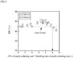
- Table 4 shows a blending condition of an easily softening coal blended with the hardly softening coal, value obtained by multiplying CSN of the easily softening coal by a weight ratio of the easily softening coal to the total coal weight, and strength of ferrocoke obtained from a coal blend combined with the hardly softening coal having CSN of 1.5 and 2.0 as the examination results.
- the reason why the optimum range is existent in the value obtained by multiplying CSN of the easily softening coal by the blending weight ratio of the easily softening coal is considered due to the fact that if the value is larger, the strength after the carbonization is decreased due to the increase of the porosity associated with the swelling of the carbonized material.
- FIG.3 is shown a photograph of a fused case.
- Table 5 and FIG. 4 show results of fusion test when two kinds of hardly softening coals having CSN of 2.0 and 2.5 are carbonized in a laboratory scale to the value obtained by multiplying CSN of the easily softening coal by a blending weight ratio of the easily softening coal.
- Table 2 are shown two kinds of coals having CSN of 2.5 as hardly softening coals P and Q. In this test, these coals are blended in an each amount of 50 mass%. As seen from the results of FIG.
- the fusion ratio is not more than 10% when CSN of the hardly softening coal is 2.0. On the other hand, when CSN of the hardly softening coal is 2.5, the fusion ratio is not less than about 20%.
- the term "fusion ratio" means a mass ratio of fused ferrocoke as shown in FIG. 3 in mass of ferrocoke produced.
- the shaped bodies are carbonized at a fixed state (fixed layer).
- a continuous production it is a continuous system wherein the shaped bodies are charged from a top of a furnace such as shaft type furnace and the carbonized material is continuously discharged from a bottom of the furnace. It is commonly considered that the fusion is apt to be caused in the carbonization at the fixed layer as compared to the continuous system.
- the inventors have made a test in a carbonization furnace of a laboratory scale on the shaped bodies causing poor discharge associated with fusion inside the furnace in the continuous shaft type carbonization bench plant in order to evaluate the difference of fusion ratios between the carbonization in the fixed layer and the continuous carbonization.
- the shaped bodies showing the fusion ratio of not less than 10% cause the poor discharge associated with the fusion inside the furnace in the continuous carbonization furnace.
- the dotted line in FIG. 4 shows a lower limit of the fusion ratio causing the poor discharge in the continuous carbonization furnace.
- coal, iron ore and binder are mixed so as to render each blending ratio into 65.8 mass%, 28.2 mass% and 6 mass% to the total weight of these raw materials, respectively.
- a coal A in Table 1 is used as an easily softening coal and a coal O in Table 2 is used as a hardly softening coal.
- a blending ratio of the easily softening coal to the hardly softening coal is 1/9 and 7/3.
- a value obtained by multiplying CSN of the easily softening coal by a weight ratio of the easily softening coal to the total coal weight is 0.25, which is obtained by multiplying CSN of 2.5 of the coal A by the blending ratio of 0.1 of the easily softening coal in the case of 1/9.
- the value is 1.75, which is obtained by multiplying CSN of 2.5 of the coal A by the blending ratio of 0.7 of the easily softening coal.
- a shaft type carbonization furnace of 0.3 t/d shown in FIG. 5 It is a continuous countercurrent type furnace made of SUS and having a size of 0.25 m in diameter x 3 m in height and provided with a cooling equipment for generated gas.
- Thermocouples are disposed at an interval of about 10-20 cm in a center of a reaction tube from the top of the furnace toward a cooling zone at a bottom of the furnace to determine heating conditions for a predetermined heat pattern.
- an upper stage electric furnace is set to 700°C and a lower stage electric furnace is set to 850°C, and further a high-temperature gas of 850°C is passed from the bottom of the furnace at a flow rate of 60 L/min.
- FIG. 6 shows a heat pattern when the temperature in the lower stage electric furnace and the high temperature gas is set to 850°C.
- a highest achieving temperature in the center of the reaction tube is 852°C, and a time keeping this temperature is about 60 minutes.
- Green briquettes are charged into the inside of the furnace from the top of the furnace through a double valve, while carbonized ferrocoke is continuously discharged from the bottom of the furnace. Ferrocoke discharged at an interval of 30 minutes is taken out to measure a strength. The results are shown in FIG. 7 .
- a carbonized material is discharged from the start of ferrocoke discharge up to 2 hours under a condition that a carbonization temperature of a shaped body is not sufficient, so that the ferrocoke strength is low.
- the discharge of ferrocoke becomes steady at a time exceeding 2 hours from the start of the discharge.
- CSN*blending ratio of easily softening coal is 1.75
- the target strength is stably held at a time exceeding 2 hours from the start of the discharge.
- CSN*blending ratio of easily softening coal is 0.25, the strength becomes constant at a state of falling down the target value.
- a coal having a button index (CSN) of 1.0 and a volatile matter of not less than 17.0% or a button index (CSN) of 1.5-2.0 is used as the hardly softening coal and the easily softening coal satisfies that a value obtained by multiplying CSN of the easily softening coal by a blending ratio thereof to the total coal is within a range of 0.3-5.2.
- a coal having a button index (CSN) of 1.5-2.0 is used as the hardly softening coal and the easily softening coal satisfies that a value obtained by multiplying CSN of the easily softening coal by a blending ratio thereof to total coal weight is not more than 5.0.
- ferrocoke manufacturing method can be manufactured ferrocoke having a high strength and being low in cost and high in the reactivity, and it is possible to operate a blast furnace at a low reducing material ratio by using the thus obtained ferrocoke as a coal material.
Landscapes
- Chemical & Material Sciences (AREA)
- Engineering & Computer Science (AREA)
- Organic Chemistry (AREA)
- Oil, Petroleum & Natural Gas (AREA)
- Materials Engineering (AREA)
- Metallurgy (AREA)
- Manufacturing & Machinery (AREA)
- Life Sciences & Earth Sciences (AREA)
- Environmental & Geological Engineering (AREA)
- General Life Sciences & Earth Sciences (AREA)
- Geochemistry & Mineralogy (AREA)
- Geology (AREA)
- Mechanical Engineering (AREA)
- Coke Industry (AREA)
- Solid Fuels And Fuel-Associated Substances (AREA)
Abstract
Description
- This invention relates to a ferrocoke manufacturing method by carbonizing a mixture of coal and iron ore.
- Recently, the operation of a blast furnace is strongly demanded to improve reduction reaction in the furnace from a viewpoint of consideration to the global environment. In this connection, attention is paid to the use of ferrocoke obtained by shaping and carbonizing a mixture of coal and iron ore.
- The ferrocoke is usually manufactured by using an easily softening coal (caking coal, strong caking coal) indicating a softening and melting property during carbonization of coal and/or a hardly softening coal (non-slightly caking coal, non-caking coal) suppressing fusion between mutual shaped bodies. The hardly softening coal has a maximum fluidity of less than 2 ddpm measured by Gieseler plastometer described in JIS M8801. On the other hand, it is important that ferrocoke has an excellent reactivity, but it is required to have a certain strength because deterioration of gas permeability in the blast furnace is caused if it is easily powdered in the blast furnace. In general, a blending ratio of coal to iron ore is frequently made to about 7:3. When the ratio of iron ore is lower than the above value, the reactivity of ferrocoke tends to be decreased, while when it exceeds the above value, the improvement of the reactivity is small and the strength of ferrocoke tends to be largely decreased. As to the strength, a target drum strength of ferrocoke (150 revolutions, 6 mm index) is defined to be not less than 82 in "Research on innovative iron-making process" performed since 2006 by the New Energy and Industrial Technology Development Organization, for example.
- As an example of ferrocoke,
Patent Document 1 discloses a method wherein semi-anthracite having a volatile matter of not more than 18 mass% and/or anthracite are/is blended to perform size control for suppressing fusion of the ferrocoke and maintaining strength. Also,Patent Document 2 discloses that a blending ratio of non-caking coal is defined based on a ratio of Fe to O in iron ore in the blending of hardly softening coal (non-caking coal or coal having no caking property described in Patent Document 2). Further,Patent Document 3 discloses that iron sand is used as an iron source and a blending ratio of non-caking coal is determined in accordance with a blending ratio of the iron sand. In the ferrocoke disclosed in these documents, a substance having no caking property or a maximum fluidity of 0 ddpm such as non-caking coal, lignite, anthracite, petroleum coke, coal or the like is used as a raw material. - Thus, the conventional ferrocoke mainly uses coal having no caking property (substance having a maximum fluidity of 0 ddpm such as non-caking coal, lignite, anthracite, petroleum coke, coal) as a raw material. However, coal indicating slight swelling by an evaluation of button index (hereinafter abbreviated as "CSN") described in JIS M8801 exists in the coals having a maximum fluidity (hereinafter abbreviated as "MF") of 0 ddpm, so that it is considered that coke further increasing the strength of the ferrocoke is existent in the coals having MF of 0 ddpm. Moreover, CSN means an index of discrete value such as 1, 1.5, 2, .... 9 fitted when a test sample is placed in an exclusive crucible and rapidly heated at 820°C and a form of a coke cake after resolidification is compared to a standard profile diagram. As the index value becomes smaller, the caking property becomes poorer.
- As regards the button index (CSN), there is a technique disclosed, for example, in
Patent Document 4 as a conventional technique for the manufacture of shaped coke instead of the ferrocoke. In the examples of this document is described a case of blending an inferior quality coal having CSN of 0.5. InPatent Documents Patent Document 7 is described a case of blending a non-caking coal or a fine caking coal having CSN of 0-1 and a fine caking coal having CSN of 1.5. In the case of blending the fine caking coal having CSN of 1.5, the strength of the shaped coke is low. - All the raw material for the shaped coke is usually constructed with carbon material. In the case of ferrocoke containing an iron ore of different characteristics from coal, however, the iron ore has no effect of the improvement of ferrocoke, so that it is considered that it is preferable to use coal having MF of more than 0 ddpm and CSN of not less than 0 as a carbon material. As to the blending of raw materials for ferrocoke, the blending ratio has hitherto been described as in
Patent Documents -
- Patent Document 1: Japanese Patent No.
5017969 - Patent Document 2: Japanese Patent No.
4892929 - Patent Document 3: Japanese Patent No.
4892930 - Patent Document 4:
JP-A-S57-80481 - Patent Document 5:
JP-B-S62-45914 - Patent Document 6:
JP-B-S59-8313 - Patent Document 7:
JP-B-S52-20481 - Ferrocoke is usually manufactured by carbonizing a shaped body of a mixture of a carbon material such as coal and an iron ore as an iron source in an exclusive shaft furnace. Also, the ferrocoke is required to have a high reactivity and a high strength. In order to obtain the high reactivity of the ferrocoke, it is considered to increase blending of an iron ore or an easily softening coal having a low carbon content. However, the increase of blending the iron ore is apt to bring about the decrease of ferrocoke strength, so that it is considered that the use of the easily softening coal having a low carbon content is more preferable because the decrease of the strength becomes smaller. On the other hand, since the easily softening coal having a low carbon content is high in the volatile matter, there is a risk of increasing the porosity of ferrocoke, so that there is a problem that the fear of causing the decrease of the strength is high as compared to coal having a high carbon content.
- In order to solve the above problem, it is necessary to use a coal improving the ferrocoke strength as a hardly softening coal blended for the purpose of suppressing the fusion between the mutual shaped bodies in the shaft type carbonization furnace. In general, it is known that the fusion between the mutual shaped bodies is easily caused when a large amount of an easily swelling coal or a coal having a small shrinking quantity is blended. In order to increase the ferrocoke strength, therefore, it is necessary to selectively use a coal swelling to a certain level and being small in the shrinking quantity, so that the selection of a hardly softening coal is important like that of the easily softening coal.
- It is an object of the invention to propose a method effective for manufacturing high-strength ferrocoke without causing the fusion between the mutual shaped bodies.
- The inventors have made various studies on the aforementioned problems inherent to the conventional techniques and found that the ferrocoke strength can be increased by setting the button index of the hardly softening coal as a raw coal material for the manufacture of ferrocoke to a preferable range without causing the fusion between the mutual shaped bodies, and as a result the invention has been accomplished. Furthermore, it has been found that similar results can be obtained by properly adjusting the nature and blending amount of the easily softening coal in accordance with the nature of the hardly softening coal, and it becomes possible to select the raw materials within a wider range.
- That is, the invention is a ferrocoke manufacturing method by shaping and carbonizing a mixture of coal and iron ore, characterized in that a hardly softening coal having a button index (CSN) of not more than 2.0 is used as the coal.
- In the ferrocoke manufacturing method according to the invention, the followings are considered to be preferable solution means:
- (1) a hardly softening coal having a button index (CSN) of 1.5-2.0 is used as the coal;
- (2) the coal is a blend of a hardly softening coal and an easily softening coal, and the hardly softening coal has a button index (CSN) of 1.0 and a volatile matter of not less than 17%, and the easily softening coal satisfies that a value obtained by multiplying CSN of the easily softening coal by a blending ratio thereof in all coals is in a range of 0.3-5.2;
- (3) the blending ratio of the easily softening coal in all coals is not more than 0.8; and
- (4) the coal is a blend of the hardly softening coal and the easily softening coal, and the hardly softening coal is a coal having a button index (CSN) of 1.5-2.0, and the easily softening coal satisfies that a value obtained by multiplying CSN of the easily softening coal by a blending ratio thereof in all coals is not more than 5.0.
- According to the invention having the aforementioned construction, ferrocoke having a required strength can be manufactured even when only the hardly softening coal is used, and also it is possible to select coals within a wider range by selecting the easily softening coal in accordance with the nature of the hardly softening coal, and it is possible to manufacture ferrocoke having a higher strength even when a coal having a low carbon content and being low in the cost is used as the easily softening coal. Also, when a coal having a low carbon content can be used by applying the invention, ferrocoke having a higher reactivity can be obtained, which largely contributes to the operation of the blast furnace at a low reducing material ratio.
-
-
FIG. 1 is a graph showing a relation between CSN of an easily softening coal and a blending ratio of an easily softening coal exerting a strength after carbonization in the case of using a hardly softening coal with a button index (CSN) of 1.0. -
FIG. 2 is a graph showing a relation between CSN of an easily softening coal and a blending ratio of an easily softening coal exerting a strength after carbonization in the case of using a hardly softening coal with a button index (CSN) of 1.5 and 2.0. -
FIG. 3 is a photograph showing an appearance of fused ferrocoke. -
FIG. 4 is a diagram showing an influence of CSN of a hardly softening coal upon a fusion ratio. -
FIG. 5 is a schematic view of a shaft type carbonization furnace. -
FIG. 6 is a graph showing a heat pattern inside a shaft type carbonization furnace. -
FIG. 7 is a graph showing a change of ferrocoke strength with lapse of time. - The invention is a ferrocoke manufacturing method having a high strength and a high reactivity without causing the decrease of the strength even if an inferior quality coal is used. That is, this method is characterized in that when a mixture of coal and iron ore is shaped and carbonized to manufacture ferrocoke, a coal having a button index (CSN) of not more than 2.0 is used as a hardly softening coal. The reason why the button index (CSN) of the hardly softening coal is limited to not more than 2.0 is due to the fact that when a coal having a CSN value of more than 2.0 is used, if a shaped body of this hardly softening coal and an iron ore (a weight ratio of the iron ore in the mixture of the hardly softening coal and the iron ore is 30 mass%) is carbonized, fusion between the mutual shaped bodies is generated inevitably and hence the effect of suppressing the fusion by the addition of the hardly softening coal cannot be obtained.
- The lower limit of the button index (CSN) of the hardly softening coal is not particularly limited. However, when the button index (CSN) of the hardly softening coal is 1.0, a target strength may not be attained in accordance with a volatile matter of the hardly softening coal as seen from examples mentioned later, so that the button index (CSN) of the hardly softening coal is preferable to be 1.5-2.0.
- In examples according to the invention that the coal is a blend of hardly softening coal and easily softening coal and the hardly softening coal is a coal having a button index (CSN) of 1.5-2.0, it is preferable that the easily softening coal satisfies that a value obtained by multiplying CSN of the easily softening coal by a blending ratio thereof in all coals is not more than 5.0. Furthermore, in examples according to the invention that the coal is a blend of hardly softening coal and easily softening coal and the hardly softening coal is a coal having a button index (CSN) of 1.0, it is preferable that the hardly softening coal is a coal having a volatile matter of not less than 17% and the easily softening coal satisfies that a value obtained by multiplying CSN of the easily softening coal by a blending ratio thereof in all coals is within a range of 0.3-5.2. Moreover, the volatile matter is measured according to JIS M8812 and represented by dry ash free base.
- There will be described preferable examples using a blend of a hardly softening coal and an easily softening coal below.
- This experiment is performed according to the following process. A shaped body is manufactured by changing each CSN of a hardly softening coal and an easily softening coal (carbon content and MF are varied with the change of CSN) to evaluate strength after carbonization (ferrocoke strength). The hardly softening coal and the easily softening coal are blended so as to render coals of plural brands into predetermined CSN and carbon content. As a quality of the coal used, Table 1 shows a grade of the easily softening coal and Table 2 shows a grade of the hardly softening coal. As an iron ore are used ones having a total iron content of 57 mass%. A pulverized grain size of each of the coal and iron ore is not more than 3 mm in total. Also, a maximum fluidity MF in Table 2 is measured by a Gieseler plastometer. A sensitivity is low at a lower range of MF. In this time, MF measurement of the hardly softening coal is performed five times, and an average value thereof is determined as MF value.
Table 1 Brand CSN (-) MF (ddpm) Ash content (%) A 2.5 30 21.5 B 3.0 4 9.7 C 3.5 2 18.1 D 4.5 33 8.8 E 5.0 29 8.0 F 5.5 82 7.8 G 6.0 81 8.9 H 6.5 85 7.3 I 7.0 2 8.8 Table 2 Brand MF (ddpm) CSN (-) VM (%) Ash content (%) J 0.00 1.0 12.5 12.7 K 0.00 1.0 14.6 10.8 L 0.60 1.0 17.2 10.9 M 0.40 1.0 17.2 11.3 N 1.00 1.5 17.4 9.9 O 0.80 1.5 27.5 22.5 P 1.40 2.0 22.2 10.4 Q 1.60 2.0 23.6 15.2 R 1.60 2.5 25.5 11.1 S 1.80 2.5 26.5 14.5 T 1.80 3.0 26.5 9.7 U 1.80 3.0 25.5 10.7 - Moreover, the shaping treatment is performed by the following method. That is, the coal, iron ore and binder are mixed so that blending ratios are set to 65.8 mass%, 28.2 mass% and 6 mass% to the total weight of raw materials, respectively. As to the coal, the easily softening coal and the hardly softening coal are blended. A mixture of these raw materials is kneaded in a high-speed mixer at 140-160°C for about 2 minutes, and the kneaded material is shaped into briquettes in a double roll type shaping machine. A size of the roll is 650 mm in diameter and 104 mm in width, and shaping is performed at a peripheral speed of 0.2 m/s and a linear pressure of 4 t/cm. A shaped body has a size of 30 mm x 25 mm x 18 mm (6 cc) and is oval.
- Then, the thus obtained shaped bodies are carbonized according to the following carbonization process of a laboratory scale. That is, 3 kg of the shaped bodies are filled in a carbonization can of 300 mm in both length and 400 mm in height, kept at a furnace wall temperature of 1000°C for 6 hours and then cooled in nitrogen atmosphere. The carbonized material cooled to room temperature is taken out to measure strength and evaluate a fusion ratio. The measurement of the strength is performed as a drum strength (DI150 6). In this regard, DI150 6 means a value obtained by measuring a mass ratio of coke having a grain size of not less than 6 mm under a condition of 15 rpm, 150 revolutions by a revolution strength testing method of JIS K2151. A target strength is set to not less than 82. The fusion ratio is evaluated by a weight percentage of a fused material to a total weight of the carbonized material.
- As to the results of the above experiment, ferrocoke strength to a value obtained by multiplying CSN of the easily softening coal by a weight ratio of the easily softening coal to the total coal weight is plotted in a graph of
FIG. 1 . As the hardly softening coal is used a coal having CSN of 1.0 and a volatile matter of 13.6% and 17.2%. Table 2 describes two kinds of coals having CSN of 1.0 as brands J and K of the hardly softening coal. In the case that the volatile matter is 13.6%, the brands J and K are blended in an each amount of 50 mass%, while in the case that the volatile matter is 17.2%, brands L and M are blended in an each amount of 50 mass%. - Table 3 shows a blending condition of the easily softening coal blended with the hardly softening coal, value obtained by multiplying CSN of the easily softening coal by a weight ratio of the easily softening coal to the total coal weight, and strength of ferrocoke obtained from a mixed coal blended with a coal having CSN of 1.0 as the hardly softening coal as data in the graph of
FIG. 1 . Even when any easily softening coal is used, if the hardly softening coal has CSN of 1.0 and a volatile matter of 13.6%, it can be seen that the strength after the carbonization largely falls below the target strength different from that of the examples described in the above patent documents. Since ferrocoke contains an iron ore having no compatibility with carbon materials, it is considered that the ferrocoke strength is apt to be largely decreased when being blended with a hardly softening coal hardly fused by softening and showing no swellability. - In
FIG. 1 , the plot having 0 as the value of abscissa axis shows the result in the blending of only hardly softening coals. When the volatile matter is 13.6%, the strength is largely decreased. On the other hand, when the volatile matter is 17.2%, the strength is near to the target value in the blending of only the coals. In the case that the blending ratio of the easily softening coal is 0.1-0.8, the strength exceeds the target value when the value obtained by multiplying CSN of the easily softening coal by the blending weight ratio of the easily softening coal is 0.3-5.2. Even when the volatile matter is 17.2%, it is considered that the swellability is low at CSN of 1.0, but since the coal is at a state of somewhat promoting carbonization as compared to strong caking coal, mitigation of carbon structure associated with heating is easily caused as compared to the case that the volatile matter is 13.6%. To this end, it is guessed that the coal is slightly softened under carbonization condition through rapid heating as in this experiment (rapid heating condition even in the actual shaft furnace) and hence the strength is recognized to be in a range exceeding the target value. Moreover, the reason why the optimum range is existent in the value obtained by multiplying CSN of the easily softening coal by the blending weight ratio of the easily softening coal is considered due to the fact that when the value is small, swelling of the coal is small and the adhesion between the grains is deteriorated, while when the value is large, the strength after the carbonization is decreased by increase of porosity associated with the swelling of the carbonized material.Table 3 Blending condition of easily softening coal DI150 6 (-) Brand used CSN Blending ratio CSN*Blending ratio VM 13.6% VM 17.2% - - 0 0 16.0 76.0 A 2.5 0.05 0.13 18.0 77.0 B 3.0 0.1 0.30 25.1 82.0 C 3.5 0.2 0.70 38.0 82.0 D 4.5 0.3 1.35 43.2 82.6 D 4.5 0.6 2.70 60.0 83.2 E 5.0 0.6 3.00 58.0 84.0 F 5.5 0.8 4.40 64.0 83.5 G 6.0 0.6 3.60 68.0 84.5 H 6.5 0.8 5.20 71.0 83.0 I 7.0 0.8 5.60 69.0 80.0 - Hardly softening coals having CSN of 1.5 and 2.0 are examined below. That is, the examination is performed by blending coals N and O having CSN of 1.5 and coals P and Q having CSN of 2.0 as shown in Table 2 in an each amount of 50 mass%. Table 4 shows a blending condition of an easily softening coal blended with the hardly softening coal, value obtained by multiplying CSN of the easily softening coal by a weight ratio of the easily softening coal to the total coal weight, and strength of ferrocoke obtained from a coal blend combined with the hardly softening coal having CSN of 1.5 and 2.0 as the examination results. Based on the results of Table 4 are plotted ferrocoke strengths to the value obtained by multiplying CSN of the easily softening coal by the weight ratio of the easily softening coal to the total coal weight in the graph of
FIG. 2 .Table 4 Blending conditions of easily softening coal DI150 6 (-) Brand used CSN Blending ratio CSN*Blending ratio Hardly softening coal CSN: 1.5 Hardly softening coal CSN: 2.0 - - 0 0 82.0 82.0 A 2.5 0.1 0.25 82.1 82.4 A 2.5 0.2 0.50 82.1 82.0 B 3.0 0.2 0.60 82.3 83.3 C 3.5 0.8 2.80 84.1 84.3 D 4.5 0.4 1.80 83.8 83.0 D 4.5 0.8 3.60 85.6 85.0 E 5.0 0.4 2.00 82.4 82.0 E 5.0 0.8 4.00 84.5 85.5 F 5.5 0.6 3.30 84.5 85.8 F 5.5 0.8 4.40 84.6 84.1 G 6.0 0.6 3.60 84.0 84.1 G 6.0 0.8 4.80 83.3 82.2 H 6.5 0.2 1.30 82.5 83.0 H 6.5 0.8 5.20 81.7 81.8 I 7.0 0.4 2.80 84.6 84.0 I 7.0 0.6 4.20 83.1 84.0 - As seen from the results shown in Table 4 and
FIG. 2 , when the blending ratio of the easily softening coal is not more than 0.8, the strengths higher than that in the case that CSN of the hardly softening coal shown inFIG. 1 is 1.0 are obtained even in any values obtained by multiplying CSN of the easily softening coal by the blending weight ratio of the easily softening coal. Also, it can be seen that the strength is made to not less than the target value when the value obtained by multiplying CSN of the easily softening coal by the blending weight ratio of the easily softening coal is not more than 5.0. Moreover, the reason why the optimum range is existent in the value obtained by multiplying CSN of the easily softening coal by the blending weight ratio of the easily softening coal is considered due to the fact that if the value is larger, the strength after the carbonization is decreased due to the increase of the porosity associated with the swelling of the carbonized material. - A fear of fusing the carbonized material is caused in the case that CSN of the hardly softening coal is 2.5. In
FIG.3 is shown a photograph of a fused case. Table 5 andFIG. 4 show results of fusion test when two kinds of hardly softening coals having CSN of 2.0 and 2.5 are carbonized in a laboratory scale to the value obtained by multiplying CSN of the easily softening coal by a blending weight ratio of the easily softening coal. In Table 2 are shown two kinds of coals having CSN of 2.5 as hardly softening coals P and Q. In this test, these coals are blended in an each amount of 50 mass%. As seen from the results ofFIG. 4 , the fusion ratio is not more than 10% when CSN of the hardly softening coal is 2.0. On the other hand, when CSN of the hardly softening coal is 2.5, the fusion ratio is not less than about 20%. Moreover, the term "fusion ratio" means a mass ratio of fused ferrocoke as shown inFIG. 3 in mass of ferrocoke produced.Table 5 Blending conditions of easily softening coal Fusion ratio (%) Brand used CSN Blending ratio CSN*Blending ratio Hardly softening coal CSN: 2.0 Hardly softening coal: CSN: 2.5 A 2.5 0.2 0.5 3.0 12.0 A 2.5 0.6 1.5 3.0 14.0 B 3.0 0.8 2.4 6.1 15.8 D 4.5 0.8 3.6 7.1 20.5 E 5.0 0.8 4.0 8.2 22.0 F 5.5 0.2 1.1 5.3 15.0 F 5.5 0.6 3.3 4.0 19.0 G 6.0 0.2 1.2 6.1 17.0 G 6.0 0.8 4.8 7.0 20.0 H 6.5 0.8 5.2 8.7 25.0 I 7.0 0.4 2.8 5.0 16.0 I 7.0 0.8 5.6 8.8 33.0 - In this carbonization test, the shaped bodies are carbonized at a fixed state (fixed layer). In the case of a continuous production, it is a continuous system wherein the shaped bodies are charged from a top of a furnace such as shaft type furnace and the carbonized material is continuously discharged from a bottom of the furnace. It is commonly considered that the fusion is apt to be caused in the carbonization at the fixed layer as compared to the continuous system. Then, the inventors have made a test in a carbonization furnace of a laboratory scale on the shaped bodies causing poor discharge associated with fusion inside the furnace in the continuous shaft type carbonization bench plant in order to evaluate the difference of fusion ratios between the carbonization in the fixed layer and the continuous carbonization. In this carbonization test, the shaped bodies showing the fusion ratio of not less than 10% cause the poor discharge associated with the fusion inside the furnace in the continuous carbonization furnace. The dotted line in
FIG. 4 shows a lower limit of the fusion ratio causing the poor discharge in the continuous carbonization furnace. When CSN of the hardly softening coal is 2.5, a fear of fusion becomes large in the continuous carbonization, so that the upper limit of CSN in the hardly softening coal is revealed to be 2.0. - In this example, coal, iron ore and binder are mixed so as to render each blending ratio into 65.8 mass%, 28.2 mass% and 6 mass% to the total weight of these raw materials, respectively. A coal A in Table 1 is used as an easily softening coal and a coal O in Table 2 is used as a hardly softening coal. A blending ratio of the easily softening coal to the hardly softening coal is 1/9 and 7/3. Thus, a value obtained by multiplying CSN of the easily softening coal by a weight ratio of the easily softening coal to the total coal weight is 0.25, which is obtained by multiplying CSN of 2.5 of the coal A by the blending ratio of 0.1 of the easily softening coal in the case of 1/9. In the case of 7/3, the value is 1.75, which is obtained by multiplying CSN of 2.5 of the coal A by the blending ratio of 0.7 of the easily softening coal.
- In the carbonization test is used a shaft type carbonization furnace of 0.3 t/d shown in
FIG. 5 . It is a continuous countercurrent type furnace made of SUS and having a size of 0.25 m in diameter x 3 m in height and provided with a cooling equipment for generated gas. Thermocouples are disposed at an interval of about 10-20 cm in a center of a reaction tube from the top of the furnace toward a cooling zone at a bottom of the furnace to determine heating conditions for a predetermined heat pattern. In this example, an upper stage electric furnace is set to 700°C and a lower stage electric furnace is set to 850°C, and further a high-temperature gas of 850°C is passed from the bottom of the furnace at a flow rate of 60 L/min.FIG. 6 shows a heat pattern when the temperature in the lower stage electric furnace and the high temperature gas is set to 850°C. A highest achieving temperature in the center of the reaction tube is 852°C, and a time keeping this temperature is about 60 minutes. Green briquettes are charged into the inside of the furnace from the top of the furnace through a double valve, while carbonized ferrocoke is continuously discharged from the bottom of the furnace. Ferrocoke discharged at an interval of 30 minutes is taken out to measure a strength. The results are shown inFIG. 7 . - The followings are understood from the results of
FIG. 7 . Firstly, a carbonized material is discharged from the start of ferrocoke discharge up to 2 hours under a condition that a carbonization temperature of a shaped body is not sufficient, so that the ferrocoke strength is low. However, the discharge of ferrocoke becomes steady at a time exceeding 2 hours from the start of the discharge. In the case that CSN*blending ratio of easily softening coal is 1.75, the target strength is stably held at a time exceeding 2 hours from the start of the discharge. In the case that CSN*blending ratio of easily softening coal is 0.25, the strength becomes constant at a state of falling down the target value. - From the above is understood that the preferable conditions of hardly softening coal and easily softening coal for manufacturing a high-strength ferrocoke are as follows.
- In order to manufacture a high-strength ferrocoke, it is important on the premise of using a blend of easily softening coal and hardly softening coal that a coal having a button index (CSN) of 1.0 and a volatile matter of not less than 17.0% or a button index (CSN) of 1.5-2.0 is used as the hardly softening coal and the easily softening coal satisfies that a value obtained by multiplying CSN of the easily softening coal by a blending ratio thereof to the total coal is within a range of 0.3-5.2.
- Also, in order to manufacture a high-strength ferrocoke, it is important on the premise of using a blend of easily softening coal and hardly softening coal that a coal having a button index (CSN) of 1.5-2.0 is used as the hardly softening coal and the easily softening coal satisfies that a value obtained by multiplying CSN of the easily softening coal by a blending ratio thereof to total coal weight is not more than 5.0.
- According to the ferrocoke manufacturing method according to the invention can be manufactured ferrocoke having a high strength and being low in cost and high in the reactivity, and it is possible to operate a blast furnace at a low reducing material ratio by using the thus obtained ferrocoke as a coal material.
Claims (5)
- A ferrocoke manufacturing method by shaping and carbonizing a mixture of coal and iron ore, characterized in that a hardly softening coal having a button index (CSN) of not more than 2.0 is used as the coal.
- The ferrocoke manufacturing method according to claim 1, wherein a hardly softening coal having a button index (CSN) of 1.5-2.0 is used as the coal.
- The ferrocoke manufacturing method according to claim 1, wherein the coal is a blend of a hardly softening coal and an easily softening coal, and the hardly softening coal has a button index (CSN) of 1.0 and a volatile matter of not less than 17%, and the easily softening coal satisfies that a value obtained by multiplying CSN of the easily softening coal by a blending ratio thereof in all coals is a range of 0.3-5.2.
- The ferrocoke manufacturing method according to claim 3, wherein the blending ratio of the easily softening coal in all coals is not more than 0.8.
- The ferrocoke manufacturing method according to claim 1, wherein the coal is a blend of the hardly softening coal and the easily softening coal, and the hardly softening coal is a coal having a button index (CSN) of 1.5-2.0, and the easily softening coal satisfies that a value obtained by multiplying CSN of the easily softening coal by a blending ratio thereof in all coals is not more than 5.0.
Applications Claiming Priority (2)
| Application Number | Priority Date | Filing Date | Title |
|---|---|---|---|
| JP2015021695 | 2015-02-06 | ||
| PCT/JP2016/052875 WO2016125727A1 (en) | 2015-02-06 | 2016-02-01 | Ferrocoke manufacturing method |
Publications (3)
| Publication Number | Publication Date |
|---|---|
| EP3255122A1 true EP3255122A1 (en) | 2017-12-13 |
| EP3255122A4 EP3255122A4 (en) | 2018-01-24 |
| EP3255122B1 EP3255122B1 (en) | 2023-06-07 |
Family
ID=56564072
Family Applications (1)
| Application Number | Title | Priority Date | Filing Date |
|---|---|---|---|
| EP16746558.2A Active EP3255122B1 (en) | 2015-02-06 | 2016-02-01 | Ferrocoke manufacturing method |
Country Status (6)
| Country | Link |
|---|---|
| US (1) | US11486022B2 (en) |
| EP (1) | EP3255122B1 (en) |
| JP (2) | JP6210156B2 (en) |
| KR (1) | KR101910405B1 (en) |
| CN (1) | CN107207966B (en) |
| WO (1) | WO2016125727A1 (en) |
Families Citing this family (1)
| Publication number | Priority date | Publication date | Assignee | Title |
|---|---|---|---|---|
| JP7647718B2 (en) * | 2022-10-04 | 2025-03-18 | Jfeスチール株式会社 | Evaluation method for coal for ferro-coke. |
Family Cites Families (20)
| Publication number | Priority date | Publication date | Assignee | Title |
|---|---|---|---|---|
| JPS598313B2 (en) | 1975-03-28 | 1984-02-23 | 住友金属工業株式会社 | Method for manufacturing molded coke for metallurgy |
| JPS5423604A (en) * | 1977-07-23 | 1979-02-22 | Sumitomo Metal Ind Ltd | Production of molded coal |
| JPS5480302A (en) * | 1977-12-09 | 1979-06-27 | Kawasaki Steel Co | Method of making improved coal to be served for production of blast furnace coke |
| US4318779A (en) * | 1979-05-14 | 1982-03-09 | Sumikin Coke Company Ltd. | Method of manufacture of blast furnace cokes containing substantial amounts of low grade coals |
| JPS5780481A (en) | 1980-11-10 | 1982-05-20 | Sumikin Coke Co Ltd | Production of coke by blending low-grade coal in high proportion |
| JPS63137989A (en) | 1986-11-28 | 1988-06-09 | Sumitomo Metal Ind Ltd | Production of ferrocoke |
| JP4487564B2 (en) | 2002-12-25 | 2010-06-23 | Jfeスチール株式会社 | Ferro-coke manufacturing method |
| JP4267390B2 (en) | 2003-08-07 | 2009-05-27 | 新日本製鐵株式会社 | Method for producing ferro-coke for blast furnace |
| JP4892930B2 (en) | 2005-11-01 | 2012-03-07 | Jfeスチール株式会社 | Ferro-coke manufacturing method |
| JP4892929B2 (en) | 2005-11-01 | 2012-03-07 | Jfeスチール株式会社 | Ferro-coke manufacturing method |
| JP5017969B2 (en) | 2006-08-31 | 2012-09-05 | Jfeスチール株式会社 | Ferro-coke raw material molding and method for producing ferro-coke |
| RU2352605C1 (en) | 2008-01-09 | 2009-04-20 | Борис Анатольевич Мусохранов | Development method of coal mixtures for production of chargte for carbonisation and composition of such mixtures (versions) |
| JP5386838B2 (en) * | 2008-03-21 | 2014-01-15 | Jfeスチール株式会社 | Ferro-coke for metallurgy |
| JP5220481B2 (en) | 2008-05-30 | 2013-06-26 | 独立行政法人森林総合研究所 | Method for measuring wood density by laser-induced plasma emission analysis |
| JP5177101B2 (en) * | 2008-09-16 | 2013-04-03 | 新日鐵住金株式会社 | Method for producing highly reactive small coke |
| JP5466106B2 (en) * | 2009-07-31 | 2014-04-09 | 株式会社神戸製鋼所 | Method for producing iron ore-containing coke |
| JP2011037963A (en) | 2009-08-10 | 2011-02-24 | Jfe Steel Corp | Manufacturing method for ferro-coke |
| JP2011084734A (en) * | 2009-09-15 | 2011-04-28 | Jfe Steel Corp | Method for producing ferro coke |
| KR101418053B1 (en) * | 2012-12-21 | 2014-07-09 | 주식회사 포스코 | Coal briquettes and method for manufacturing the same |
| JP6245914B2 (en) | 2013-10-01 | 2017-12-13 | 共同印刷株式会社 | Identification code reading system and method |
-
2016
- 2016-02-01 JP JP2016538825A patent/JP6210156B2/en active Active
- 2016-02-01 KR KR1020177021736A patent/KR101910405B1/en active Active
- 2016-02-01 WO PCT/JP2016/052875 patent/WO2016125727A1/en not_active Ceased
- 2016-02-01 CN CN201680007312.2A patent/CN107207966B/en active Active
- 2016-02-01 US US15/548,900 patent/US11486022B2/en active Active
- 2016-02-01 EP EP16746558.2A patent/EP3255122B1/en active Active
-
2017
- 2017-08-02 JP JP2017149902A patent/JP2017193723A/en active Pending
Also Published As
| Publication number | Publication date |
|---|---|
| US11486022B2 (en) | 2022-11-01 |
| EP3255122A4 (en) | 2018-01-24 |
| CN107207966A (en) | 2017-09-26 |
| CN107207966B (en) | 2020-05-15 |
| US20180023166A1 (en) | 2018-01-25 |
| KR101910405B1 (en) | 2018-10-22 |
| EP3255122B1 (en) | 2023-06-07 |
| KR20170103862A (en) | 2017-09-13 |
| JPWO2016125727A1 (en) | 2017-04-27 |
| JP6210156B2 (en) | 2017-10-11 |
| WO2016125727A1 (en) | 2016-08-11 |
| JP2017193723A (en) | 2017-10-26 |
Similar Documents
| Publication | Publication Date | Title |
|---|---|---|
| EP2832822B1 (en) | Coal blending method for coke production, production method for coke | |
| EP2239344B1 (en) | Self-fluxing pellets for use in a blast furnace and process for the production of the same | |
| EP2463356A1 (en) | Process for producing ferro coke | |
| EP3124574B1 (en) | Method for producing coal mixture and method for producing coke | |
| KR101649672B1 (en) | Method for sample quality prediction and Method for forecasting CSR(Coke Strength Reaction) | |
| KR101879554B1 (en) | Metallurgical coke and method for producing the same | |
| JP5059379B2 (en) | Hot briquette iron for blast furnace charging raw material and method for producing the same | |
| JPS5811914B2 (en) | Method for manufacturing coke for blast furnaces | |
| EP3255122B1 (en) | Ferrocoke manufacturing method | |
| EP3315585B1 (en) | Method for producing ferrocoke | |
| JP5045039B2 (en) | Manufacturing method of high strength coke | |
| JP5590071B2 (en) | Manufacturing method of high strength coke | |
| KR102044317B1 (en) | Manufacturing apparatus of molten iron and manufacturing method of molten iron | |
| JP5833473B2 (en) | Coke production raw material production method and coke production raw material produced by the production method | |
| EP4660282A1 (en) | Coke production method | |
| JP4888452B2 (en) | Method for producing blast furnace coke | |
| JP6678095B2 (en) | Coke strength estimation method and coke production method | |
| TWI498418B (en) | A method for producing a raw material for producing coke and a raw material for coke production produced by the production method | |
| JP5453993B2 (en) | Ferro-coke manufacturing method | |
| JP2023118244A (en) | Method for determining particle size of low-shrinkage carbonaceous material and method for producing coke | |
| CN104204140B (en) | For manufacturing the preparation method of the coal mixtures of coke and coal mixtures and coke manufacture method | |
| EP3315584A1 (en) | Method for producing molded product for ferro-coke | |
| WO2016056331A1 (en) | Method for deciding blending amount of ash-free coal, and process for producing coke for blast furnace | |
| JP2002285209A (en) | Raw material charging method to blast furnace |
Legal Events
| Date | Code | Title | Description |
|---|---|---|---|
| STAA | Information on the status of an ep patent application or granted ep patent |
Free format text: STATUS: THE INTERNATIONAL PUBLICATION HAS BEEN MADE |
|
| PUAI | Public reference made under article 153(3) epc to a published international application that has entered the european phase |
Free format text: ORIGINAL CODE: 0009012 |
|
| STAA | Information on the status of an ep patent application or granted ep patent |
Free format text: STATUS: REQUEST FOR EXAMINATION WAS MADE |
|
| 17P | Request for examination filed |
Effective date: 20170724 |
|
| AK | Designated contracting states |
Kind code of ref document: A1 Designated state(s): AL AT BE BG CH CY CZ DE DK EE ES FI FR GB GR HR HU IE IS IT LI LT LU LV MC MK MT NL NO PL PT RO RS SE SI SK SM TR |
|
| AX | Request for extension of the european patent |
Extension state: BA ME |
|
| A4 | Supplementary search report drawn up and despatched |
Effective date: 20180103 |
|
| RIC1 | Information provided on ipc code assigned before grant |
Ipc: C22B 1/245 20060101ALI20171219BHEP Ipc: C10B 53/08 20060101AFI20171219BHEP Ipc: C10B 57/06 20060101ALI20171219BHEP Ipc: C21B 5/00 20060101ALI20171219BHEP |
|
| DAV | Request for validation of the european patent (deleted) | ||
| DAX | Request for extension of the european patent (deleted) | ||
| STAA | Information on the status of an ep patent application or granted ep patent |
Free format text: STATUS: EXAMINATION IS IN PROGRESS |
|
| 17Q | First examination report despatched |
Effective date: 20190514 |
|
| GRAP | Despatch of communication of intention to grant a patent |
Free format text: ORIGINAL CODE: EPIDOSNIGR1 |
|
| STAA | Information on the status of an ep patent application or granted ep patent |
Free format text: STATUS: GRANT OF PATENT IS INTENDED |
|
| RIC1 | Information provided on ipc code assigned before grant |
Ipc: C22B 1/242 20060101ALI20221208BHEP Ipc: C21B 13/00 20060101ALI20221208BHEP Ipc: C21B 5/00 20060101ALI20221208BHEP Ipc: C10B 57/06 20060101ALI20221208BHEP Ipc: C10B 53/08 20060101AFI20221208BHEP |
|
| INTG | Intention to grant announced |
Effective date: 20230103 |
|
| GRAS | Grant fee paid |
Free format text: ORIGINAL CODE: EPIDOSNIGR3 |
|
| GRAA | (expected) grant |
Free format text: ORIGINAL CODE: 0009210 |
|
| STAA | Information on the status of an ep patent application or granted ep patent |
Free format text: STATUS: THE PATENT HAS BEEN GRANTED |
|
| AK | Designated contracting states |
Kind code of ref document: B1 Designated state(s): AL AT BE BG CH CY CZ DE DK EE ES FI FR GB GR HR HU IE IS IT LI LT LU LV MC MK MT NL NO PL PT RO RS SE SI SK SM TR |
|
| REG | Reference to a national code |
Ref country code: GB Ref legal event code: FG4D |
|
| REG | Reference to a national code |
Ref country code: CH Ref legal event code: EP Ref country code: AT Ref legal event code: REF Ref document number: 1575013 Country of ref document: AT Kind code of ref document: T Effective date: 20230615 |
|
| REG | Reference to a national code |
Ref country code: DE Ref legal event code: R096 Ref document number: 602016079934 Country of ref document: DE |
|
| REG | Reference to a national code |
Ref country code: LT Ref legal event code: MG9D |
|
| REG | Reference to a national code |
Ref country code: NL Ref legal event code: MP Effective date: 20230607 |
|
| PG25 | Lapsed in a contracting state [announced via postgrant information from national office to epo] |
Ref country code: SE Free format text: LAPSE BECAUSE OF FAILURE TO SUBMIT A TRANSLATION OF THE DESCRIPTION OR TO PAY THE FEE WITHIN THE PRESCRIBED TIME-LIMIT Effective date: 20230607 Ref country code: NO Free format text: LAPSE BECAUSE OF FAILURE TO SUBMIT A TRANSLATION OF THE DESCRIPTION OR TO PAY THE FEE WITHIN THE PRESCRIBED TIME-LIMIT Effective date: 20230907 Ref country code: ES Free format text: LAPSE BECAUSE OF FAILURE TO SUBMIT A TRANSLATION OF THE DESCRIPTION OR TO PAY THE FEE WITHIN THE PRESCRIBED TIME-LIMIT Effective date: 20230607 |
|
| REG | Reference to a national code |
Ref country code: AT Ref legal event code: MK05 Ref document number: 1575013 Country of ref document: AT Kind code of ref document: T Effective date: 20230607 |
|
| PG25 | Lapsed in a contracting state [announced via postgrant information from national office to epo] |
Ref country code: RS Free format text: LAPSE BECAUSE OF FAILURE TO SUBMIT A TRANSLATION OF THE DESCRIPTION OR TO PAY THE FEE WITHIN THE PRESCRIBED TIME-LIMIT Effective date: 20230607 Ref country code: NL Free format text: LAPSE BECAUSE OF FAILURE TO SUBMIT A TRANSLATION OF THE DESCRIPTION OR TO PAY THE FEE WITHIN THE PRESCRIBED TIME-LIMIT Effective date: 20230607 Ref country code: LV Free format text: LAPSE BECAUSE OF FAILURE TO SUBMIT A TRANSLATION OF THE DESCRIPTION OR TO PAY THE FEE WITHIN THE PRESCRIBED TIME-LIMIT Effective date: 20230607 Ref country code: LT Free format text: LAPSE BECAUSE OF FAILURE TO SUBMIT A TRANSLATION OF THE DESCRIPTION OR TO PAY THE FEE WITHIN THE PRESCRIBED TIME-LIMIT Effective date: 20230607 Ref country code: HR Free format text: LAPSE BECAUSE OF FAILURE TO SUBMIT A TRANSLATION OF THE DESCRIPTION OR TO PAY THE FEE WITHIN THE PRESCRIBED TIME-LIMIT Effective date: 20230607 Ref country code: GR Free format text: LAPSE BECAUSE OF FAILURE TO SUBMIT A TRANSLATION OF THE DESCRIPTION OR TO PAY THE FEE WITHIN THE PRESCRIBED TIME-LIMIT Effective date: 20230908 |
|
| PG25 | Lapsed in a contracting state [announced via postgrant information from national office to epo] |
Ref country code: FI Free format text: LAPSE BECAUSE OF FAILURE TO SUBMIT A TRANSLATION OF THE DESCRIPTION OR TO PAY THE FEE WITHIN THE PRESCRIBED TIME-LIMIT Effective date: 20230607 |
|
| PG25 | Lapsed in a contracting state [announced via postgrant information from national office to epo] |
Ref country code: SK Free format text: LAPSE BECAUSE OF FAILURE TO SUBMIT A TRANSLATION OF THE DESCRIPTION OR TO PAY THE FEE WITHIN THE PRESCRIBED TIME-LIMIT Effective date: 20230607 |
|
| PG25 | Lapsed in a contracting state [announced via postgrant information from national office to epo] |
Ref country code: IS Free format text: LAPSE BECAUSE OF FAILURE TO SUBMIT A TRANSLATION OF THE DESCRIPTION OR TO PAY THE FEE WITHIN THE PRESCRIBED TIME-LIMIT Effective date: 20231007 |
|
| PG25 | Lapsed in a contracting state [announced via postgrant information from national office to epo] |
Ref country code: SM Free format text: LAPSE BECAUSE OF FAILURE TO SUBMIT A TRANSLATION OF THE DESCRIPTION OR TO PAY THE FEE WITHIN THE PRESCRIBED TIME-LIMIT Effective date: 20230607 Ref country code: SK Free format text: LAPSE BECAUSE OF FAILURE TO SUBMIT A TRANSLATION OF THE DESCRIPTION OR TO PAY THE FEE WITHIN THE PRESCRIBED TIME-LIMIT Effective date: 20230607 Ref country code: RO Free format text: LAPSE BECAUSE OF FAILURE TO SUBMIT A TRANSLATION OF THE DESCRIPTION OR TO PAY THE FEE WITHIN THE PRESCRIBED TIME-LIMIT Effective date: 20230607 Ref country code: PT Free format text: LAPSE BECAUSE OF FAILURE TO SUBMIT A TRANSLATION OF THE DESCRIPTION OR TO PAY THE FEE WITHIN THE PRESCRIBED TIME-LIMIT Effective date: 20231009 Ref country code: IS Free format text: LAPSE BECAUSE OF FAILURE TO SUBMIT A TRANSLATION OF THE DESCRIPTION OR TO PAY THE FEE WITHIN THE PRESCRIBED TIME-LIMIT Effective date: 20231007 Ref country code: EE Free format text: LAPSE BECAUSE OF FAILURE TO SUBMIT A TRANSLATION OF THE DESCRIPTION OR TO PAY THE FEE WITHIN THE PRESCRIBED TIME-LIMIT Effective date: 20230607 Ref country code: CZ Free format text: LAPSE BECAUSE OF FAILURE TO SUBMIT A TRANSLATION OF THE DESCRIPTION OR TO PAY THE FEE WITHIN THE PRESCRIBED TIME-LIMIT Effective date: 20230607 Ref country code: AT Free format text: LAPSE BECAUSE OF FAILURE TO SUBMIT A TRANSLATION OF THE DESCRIPTION OR TO PAY THE FEE WITHIN THE PRESCRIBED TIME-LIMIT Effective date: 20230607 |
|
| PG25 | Lapsed in a contracting state [announced via postgrant information from national office to epo] |
Ref country code: PL Free format text: LAPSE BECAUSE OF FAILURE TO SUBMIT A TRANSLATION OF THE DESCRIPTION OR TO PAY THE FEE WITHIN THE PRESCRIBED TIME-LIMIT Effective date: 20230607 |
|
| REG | Reference to a national code |
Ref country code: DE Ref legal event code: R097 Ref document number: 602016079934 Country of ref document: DE |
|
| PLBE | No opposition filed within time limit |
Free format text: ORIGINAL CODE: 0009261 |
|
| STAA | Information on the status of an ep patent application or granted ep patent |
Free format text: STATUS: NO OPPOSITION FILED WITHIN TIME LIMIT |
|
| PG25 | Lapsed in a contracting state [announced via postgrant information from national office to epo] |
Ref country code: DK Free format text: LAPSE BECAUSE OF FAILURE TO SUBMIT A TRANSLATION OF THE DESCRIPTION OR TO PAY THE FEE WITHIN THE PRESCRIBED TIME-LIMIT Effective date: 20230607 |
|
| PG25 | Lapsed in a contracting state [announced via postgrant information from national office to epo] |
Ref country code: SI Free format text: LAPSE BECAUSE OF FAILURE TO SUBMIT A TRANSLATION OF THE DESCRIPTION OR TO PAY THE FEE WITHIN THE PRESCRIBED TIME-LIMIT Effective date: 20230607 |
|
| 26N | No opposition filed |
Effective date: 20240308 |
|
| PG25 | Lapsed in a contracting state [announced via postgrant information from national office to epo] |
Ref country code: SI Free format text: LAPSE BECAUSE OF FAILURE TO SUBMIT A TRANSLATION OF THE DESCRIPTION OR TO PAY THE FEE WITHIN THE PRESCRIBED TIME-LIMIT Effective date: 20230607 Ref country code: IT Free format text: LAPSE BECAUSE OF FAILURE TO SUBMIT A TRANSLATION OF THE DESCRIPTION OR TO PAY THE FEE WITHIN THE PRESCRIBED TIME-LIMIT Effective date: 20230607 |
|
| PG25 | Lapsed in a contracting state [announced via postgrant information from national office to epo] |
Ref country code: MC Free format text: LAPSE BECAUSE OF FAILURE TO SUBMIT A TRANSLATION OF THE DESCRIPTION OR TO PAY THE FEE WITHIN THE PRESCRIBED TIME-LIMIT Effective date: 20230607 |
|
| REG | Reference to a national code |
Ref country code: CH Ref legal event code: PL |
|
| PG25 | Lapsed in a contracting state [announced via postgrant information from national office to epo] |
Ref country code: LU Free format text: LAPSE BECAUSE OF NON-PAYMENT OF DUE FEES Effective date: 20240201 |
|
| PG25 | Lapsed in a contracting state [announced via postgrant information from national office to epo] |
Ref country code: CH Free format text: LAPSE BECAUSE OF NON-PAYMENT OF DUE FEES Effective date: 20240229 |
|
| GBPC | Gb: european patent ceased through non-payment of renewal fee |
Effective date: 20240201 |
|
| PG25 | Lapsed in a contracting state [announced via postgrant information from national office to epo] |
Ref country code: LU Free format text: LAPSE BECAUSE OF NON-PAYMENT OF DUE FEES Effective date: 20240201 Ref country code: CH Free format text: LAPSE BECAUSE OF NON-PAYMENT OF DUE FEES Effective date: 20240229 |
|
| PG25 | Lapsed in a contracting state [announced via postgrant information from national office to epo] |
Ref country code: BG Free format text: LAPSE BECAUSE OF FAILURE TO SUBMIT A TRANSLATION OF THE DESCRIPTION OR TO PAY THE FEE WITHIN THE PRESCRIBED TIME-LIMIT Effective date: 20230607 |
|
| PG25 | Lapsed in a contracting state [announced via postgrant information from national office to epo] |
Ref country code: BG Free format text: LAPSE BECAUSE OF FAILURE TO SUBMIT A TRANSLATION OF THE DESCRIPTION OR TO PAY THE FEE WITHIN THE PRESCRIBED TIME-LIMIT Effective date: 20230607 |
|
| REG | Reference to a national code |
Ref country code: BE Ref legal event code: MM Effective date: 20240229 |
|
| PG25 | Lapsed in a contracting state [announced via postgrant information from national office to epo] |
Ref country code: BE Free format text: LAPSE BECAUSE OF NON-PAYMENT OF DUE FEES Effective date: 20240229 |
|
| PG25 | Lapsed in a contracting state [announced via postgrant information from national office to epo] |
Ref country code: GB Free format text: LAPSE BECAUSE OF NON-PAYMENT OF DUE FEES Effective date: 20240201 |
|
| PG25 | Lapsed in a contracting state [announced via postgrant information from national office to epo] |
Ref country code: IE Free format text: LAPSE BECAUSE OF NON-PAYMENT OF DUE FEES Effective date: 20240201 |
|
| PG25 | Lapsed in a contracting state [announced via postgrant information from national office to epo] |
Ref country code: IE Free format text: LAPSE BECAUSE OF NON-PAYMENT OF DUE FEES Effective date: 20240201 Ref country code: GB Free format text: LAPSE BECAUSE OF NON-PAYMENT OF DUE FEES Effective date: 20240201 Ref country code: BE Free format text: LAPSE BECAUSE OF NON-PAYMENT OF DUE FEES Effective date: 20240229 |
|
| PG25 | Lapsed in a contracting state [announced via postgrant information from national office to epo] |
Ref country code: CY Free format text: LAPSE BECAUSE OF FAILURE TO SUBMIT A TRANSLATION OF THE DESCRIPTION OR TO PAY THE FEE WITHIN THE PRESCRIBED TIME-LIMIT; INVALID AB INITIO Effective date: 20160201 |
|
| PG25 | Lapsed in a contracting state [announced via postgrant information from national office to epo] |
Ref country code: HU Free format text: LAPSE BECAUSE OF FAILURE TO SUBMIT A TRANSLATION OF THE DESCRIPTION OR TO PAY THE FEE WITHIN THE PRESCRIBED TIME-LIMIT; INVALID AB INITIO Effective date: 20160201 |
|
| PG25 | Lapsed in a contracting state [announced via postgrant information from national office to epo] |
Ref country code: TR Free format text: LAPSE BECAUSE OF FAILURE TO SUBMIT A TRANSLATION OF THE DESCRIPTION OR TO PAY THE FEE WITHIN THE PRESCRIBED TIME-LIMIT Effective date: 20230607 |
|
| PGFP | Annual fee paid to national office [announced via postgrant information from national office to epo] |
Ref country code: FR Payment date: 20251231 Year of fee payment: 11 |
|
| PGFP | Annual fee paid to national office [announced via postgrant information from national office to epo] |
Ref country code: DE Payment date: 20251230 Year of fee payment: 11 |