EP3254647B1 - Couche de confort pour une poche de collecte - Google Patents
Couche de confort pour une poche de collecte Download PDFInfo
- Publication number
- EP3254647B1 EP3254647B1 EP17173921.2A EP17173921A EP3254647B1 EP 3254647 B1 EP3254647 B1 EP 3254647B1 EP 17173921 A EP17173921 A EP 17173921A EP 3254647 B1 EP3254647 B1 EP 3254647B1
- Authority
- EP
- European Patent Office
- Prior art keywords
- barrier film
- collecting bag
- textile
- comfort layer
- film material
- Prior art date
- Legal status (The legal status is an assumption and is not a legal conclusion. Google has not performed a legal analysis and makes no representation as to the accuracy of the status listed.)
- Revoked
Links
Images

Classifications
-
- A—HUMAN NECESSITIES
- A61—MEDICAL OR VETERINARY SCIENCE; HYGIENE
- A61F—FILTERS IMPLANTABLE INTO BLOOD VESSELS; PROSTHESES; DEVICES PROVIDING PATENCY TO, OR PREVENTING COLLAPSING OF, TUBULAR STRUCTURES OF THE BODY, e.g. STENTS; ORTHOPAEDIC, NURSING OR CONTRACEPTIVE DEVICES; FOMENTATION; TREATMENT OR PROTECTION OF EYES OR EARS; BANDAGES, DRESSINGS OR ABSORBENT PADS; FIRST-AID KITS
- A61F5/00—Orthopaedic methods or devices for non-surgical treatment of bones or joints; Nursing devices; Anti-rape devices
- A61F5/44—Devices worn by the patient for reception of urine, faeces, catamenial or other discharge; Portable urination aids; Colostomy devices
- A61F5/4404—Details or parts
-
- B—PERFORMING OPERATIONS; TRANSPORTING
- B31—MAKING ARTICLES OF PAPER, CARDBOARD OR MATERIAL WORKED IN A MANNER ANALOGOUS TO PAPER; WORKING PAPER, CARDBOARD OR MATERIAL WORKED IN A MANNER ANALOGOUS TO PAPER
- B31B—MAKING CONTAINERS OF PAPER, CARDBOARD OR MATERIAL WORKED IN A MANNER ANALOGOUS TO PAPER
- B31B70/00—Making flexible containers, e.g. envelopes or bags
-
- A—HUMAN NECESSITIES
- A61—MEDICAL OR VETERINARY SCIENCE; HYGIENE
- A61F—FILTERS IMPLANTABLE INTO BLOOD VESSELS; PROSTHESES; DEVICES PROVIDING PATENCY TO, OR PREVENTING COLLAPSING OF, TUBULAR STRUCTURES OF THE BODY, e.g. STENTS; ORTHOPAEDIC, NURSING OR CONTRACEPTIVE DEVICES; FOMENTATION; TREATMENT OR PROTECTION OF EYES OR EARS; BANDAGES, DRESSINGS OR ABSORBENT PADS; FIRST-AID KITS
- A61F5/00—Orthopaedic methods or devices for non-surgical treatment of bones or joints; Nursing devices; Anti-rape devices
- A61F5/44—Devices worn by the patient for reception of urine, faeces, catamenial or other discharge; Portable urination aids; Colostomy devices
- A61F5/445—Colostomy, ileostomy or urethrostomy devices
-
- B—PERFORMING OPERATIONS; TRANSPORTING
- B31—MAKING ARTICLES OF PAPER, CARDBOARD OR MATERIAL WORKED IN A MANNER ANALOGOUS TO PAPER; WORKING PAPER, CARDBOARD OR MATERIAL WORKED IN A MANNER ANALOGOUS TO PAPER
- B31B—MAKING CONTAINERS OF PAPER, CARDBOARD OR MATERIAL WORKED IN A MANNER ANALOGOUS TO PAPER
- B31B70/00—Making flexible containers, e.g. envelopes or bags
- B31B70/60—Uniting opposed surfaces or edges; Taping
- B31B70/64—Uniting opposed surfaces or edges; Taping by applying heat or pressure
Definitions
- the invention relates to collecting bags for human body wastes.
- the invention relates to a textile comfort layer of a collecting bag providing the collecting bag with an increased resistance against tearing and pulling forces.
- Collecting bags for receiving and controlling human body wastes are well known and have been provided in numerous shapes, sizes and constructions for many years. Also, collecting bags being provided with a comfort layer to increase user comfort have been provided. Some examples are found in patent publications EP 1 389 081 , US 5,403,229 and US 5,759,180 .
- such a comfort layer comprises a non-woven material typically made from polyethylene, polypropylene or polyester fibres.
- the non-woven material is typically heat laminated onto the barrier material of the collecting bag or attached by a welding process.
- the welding process causes the fibre structure of the non-woven material to melt, and experience shows that this results in a relatively hard or non-flexible welding zone.
- the resulting attachment or connection between the non-woven and the barrier film layer is relatively strong, i.e. the strength required to peel the two layers apart in a peel strength test is relatively high, but in some cases the materials break instead of being peeled apart, if submitted to such a test.
- the strength of the individual non-woven fibres is compromised or greatly reduced in the melted areas of the material thereby leaving those areas more exposed to failure caused by external forces working on the collecting bag, such as tearing or pulling forces.
- the fact that the welding zone is relatively hard leaves the welding zone area exposed and much more sensitive to notches being created. In the worst case, such a failure may result in the collecting bag being torn up and open and consequently leaking its contents.
- the process of welding the non-woven onto the barrier material leaves the zone or area of the welding quite visible because all material in the welding zone is mixed and results in a relatively uniform surface after cooling, thus compromising the visual appearance of the collecting bag.
- the invention relates to a collecting bag having a textile comfort layer having at least on par peel strength characteristics with traditional non-woven material based comfort layers, but a significantly higher resistance to external forces compared to these.
- a collecting bag for human body waste having improved visual and tactile characteristics in the attachment zone(s) between the barrier film material and the comfort layer is achieved.
- the textile comfort layer has increased resistance to common wear issues such as snagging and pilling.
- the invention in a first aspect, relates to a collecting bag for human body waste comprising a barrier film covered by a comfort layer, wherein the comfort layer is a textile material having a number of threads each comprising a plurality of fibre filaments, and said textile material is attached to said barrier film in one or more zones of attachment such that not all of the fibre filaments of the textile material in said zone(s) are embedded in the barrier film material.
- a textile may be described as a flexible woven material comprising a structured network of threads consisting of fibre filaments. More specifically, the word textile refers to a material made of threads interlacing in a structured way.
- the fibre filaments are anchored by the nature of the structure itself compared to the fibres in a non-woven material that are by definition randomly arranged. This explains why a textile material typically has greater strength than non-woven materials.
- the textile comfort layer is attached to the barrier film by a heat lamination process or preferably by a welding process.
- the barrier film material (see detailed description for further detailed features of the barrier film material) will start melting at a relatively low temperature compared to the melting point temperature of the textile material, while the textile does therefore not melt and upholds and remains in its interlaced structure. This also means that the structure of the textile is maintained once the materials have cooled off. In other words, when heat is applied to weld the textile to the barrier film material, the textile does not melt, but the barrier film material melts by the heat applied.
- the melted barrier film material at least partly flows into the interlaced fibre filament structure of the threads of the textile and thereby creates a physical anchorage between the two layers without destroying the structure of the textile material.
- the textile and the barrier film materials are attached to each other while maintaining the strength of the textile material in the resulting construction.
- each thread of the textile material comprises a number of individual fibre filaments, a large resulting surface is provided for the engagement with the melted barrier film material. This has the effect that the peel strength, i.e. the strength required for separating the comfort layer from the barrier film material layer, is relatively high and on par with the peel strength for separating a comfort layer of a non-woven material from a barrier film.
- the peel strength for separating the textile material based comfort layer from the barrier film material is above 5 N/12.5mm width, such as above 6 N/12.5mm width or such as above 7 N/12.5mm width in the zone(s) of attachment.
- a comparative test is described in the experimental part of the application to support this.
- the collecting bag has the additional advantage that an increased resistance against tearing and pulling forces compared to known collecting bags with comfort layers based on non-woven materials is achieved.
- one way of describing this is to show that the collecting bag according to the invention has improved notch sensitivity. Tests have been carried out showing results supporting this finding and the results and methods of these are also presented in the experimental part of the detailed description.
- welding zone means an area of the comfort layer-barrier film construction where the materials have inter-engaged caused by the welding or heat lamination process.
- softer means that the resulting attachment or welding zone is less rigid, or more flexible, when using a textile material according to the invention, than if a non-woven material is used. This is due to the fact that the interlaced structure of the textile is maintained after the welding process, as previously described, and because some, but not all, of the fibre filaments of the threads are wholly or partially embedded in the melted barrier film material. This is fundamentally different from using a non-woven material where practically all of the non-woven and barrier film material in the welding zone melts into a continuous mass which is more hard or rigid once cooled off.
- a textile comfort layer thus also has the consequence that the attachment zone (welding zone) or area has a substantially unchanged visual appearance after the welding process.
- the welded and not-welded surface of the comfort layer looks the same.
- the physical structure, and thus the feel or tactility of the welded zone or area, is softer than is the case with the welding zone of non-woven material, partly because the textile material stays intact and only bonds with the barrier film instead of melting into a continuous mass, and partly because not all of the fibre filaments are embedded in the melted barrier film material.
- those fibre filaments that are not embedded in the barrier film material provide a surface of the comfort layer having the same tactile characteristics as the surface of the comfort layer outside the zone(s) of attachment.
- those fibre filaments that are not embedded in the barrier film material provide a surface of the comfort layer having the same visual characteristics as the surface of the comfort layer outside the zone(s) of attachment.
- a comfort layer made of a textile material provides an increased wear strength compared to the traditionally used non-woven materials in terms of improved resistance against snagging (reference is made to ASTM D3939-11 for test method) and pilling (reference is made to DS/EN ISO 12945-2:2000 for test method).
- snagging also known as a "run” in certain fine textiles such as pantyhose
- Pilling is another surface defect, caused by wear (e.g. washing and daily wearing) and resulting in small balls of fibres forming on the material surface.
- the textile material based comfort layer according to the invention advantageously has improved resistance to these defects due to the interlaced structure of the material.
- Drainable bags are often worn and used on the skin surface for a longer period of time than other types of collecting bags and are emptied on a frequent basis.
- the process of emptying the drainable collecting bag of its contents exposes the bag to friction and tension, particularly because the user often use his/her hands to squeeze or press the collecting bag over a large part of its surface to make sure it is fully emptied.
- the bag is exposed to repeated friction against the skin and the clothes of the user during normal wear, which increases the likelihood of snagging and pilling of the comfort layer surface. Therefore, when using a textile material according to the present invention, a more wear resistant collecting bag is achieved thereby reducing the risk of untimely product changes thereby adding to increased comfort for the user.
- the collecting bag comprises a first and a second barrier film sealingly joined along at least a part of their edges.
- the collecting bag may comprise two identical barrier film blanks being joined along all or part of their edges when the edges are placed on each other.
- sealingly joined is to be understood that when the barrier films are joined they form a volume of a collecting bag from which collected output, moisture and bad odour cannot unintendedly escape.
- the edges of the barrier film blanks may only be joined to each other along a part thereof, particularly in the case of a drainable collecting bag. In such examples, the edges of the barrier film blanks may be in connection with an outlet construction such as, but not limited to, valves and foldable outlet portions.
- the collecting bag further comprises an inlet opening in said barrier film.
- the collecting bag may have an inlet opening situated in said barrier film.
- one of the barrier film blanks may typically include the inlet opening.
- the inlet opening is for allowing the human body wastes to enter into the volume of the collecting bag.
- the inlet opening of the collecting bag may be placed closer to an upper edge than to a lower edge of the collecting bag as regarded when a user is wearing the collecting bag and is standing up.
- the comfort layer covers the barrier film facing the skin of the user.
- the part of the barrier film facing the skin of the user may be covered substantially wholly or only partly by the comfort layer.
- the comfort layer ensures that the collecting bag does not cling or stick to the skin surface, thereby avoiding a number of unwanted effects as described in the background section.
- the comfort layer may only be necessary or desired on part of the barrier film surface.
- the comfort layer may be provided on one or both of the barrier films, i.e. on both sides of the collecting bag, one side facing the user and one side facing away from the user.
- only a certain area percentage of the respective side or sides of the barrier film is covered by the comfort layer.
- Such area percentage may be 50 - 95 %, such as 60 - 95 %, such as 75 - 95 %, such as approximately 90 - 95 % of the barrier film's surface area.
- the collecting bag is an ostomy bag.
- the ostomy bag may be permanently attached or connected to one side of an ostomy base plate having a skin-friendly adhesive on the other side thereof for attachment to the skin of a user around a stoma.
- the base plate has a through-going hole the centre axis of which may be aligned with the centre axis of the inlet opening of the ostomy bag.
- the ostomy bag may comprise first coupling means for engagement with second mating coupling means on an ostomy base plate.
- the collecting bag is a urine collecting bag. This may include collecting bags used for continence care products, such as separate urine collecting bags having an inlet opening being connectable with one end of a urinary catheter, the other end being inserted into a user's urinary channel.
- the urine collecting bag could also be of the type being permanently attached or connected to a catheter, in the form of a set-type product solution.
- the collecting bag is a urine collecting leg bag. By mounting the urine collecting bag of the leg of a user one important aspect is that discretion is improved when moving the collecting bag away from the stomach section of the user.
- a urine collecting bag is a urostomy collecting bag.
- the collecting bag further comprises a narrowed, elongated discharge portion having a re-closable discharge opening.
- the narrowed, elongated discharge portion is typically used on drainable bags such as those provided for ileostomists or on urine bags to assist the user in emptying the bag.
- the re-closable discharge opening may comprise sealing or safety closure means.
- the discharge opening may be foldable and thus be able to be folded and kept hidden and secured, typically in a pocket of the comfort layer.
- the collecting bag of the invention may therefore comprise a zone or areas where the comfort layer is not welded to the barrier film both to facilitate the application of the narrowed, elongated discharge portion and/or to provide a pocket for securing and hiding a folded discharge portion.
- the barrier film is impermeable to water, vapour and/or gas.
- impermeable is to be understood that the barrier film is able to confine the human body waste in the volume of the collecting bag at least for a pre-defined time period.
- gas including foul smelling odours, it is important that the barrier film material is able to withstand the penetration thereof, at least for an acceptable wear-time of the product.
- the barrier film is a laminate of different layers.
- the different layers of the barrier film comprise materials such as PVDC (polyvinylidene chloride), acting as the odour retaining layer and layers containing EVA's (ethylene vinyl acetates), e.g. acting as welding or strengthening layers.
- EVA's ethylene vinyl acetates
- other polyolefin materials such as PP (polypropylene) or PE (polyethylenes) and/or tie layers (e.g. a suitable adhesive) may be included.
- the barrier films may comprise multiple-layer laminates.
- a particularly preferred barrier film is a five-layer laminate structure of the sequence EVA-tie layer-PVDC-tie layer-EVA.
- Such 5-layer barrier film laminates may be available under trade names such as SaranEX 630G from Dow Europe or Nexcel MF513 from SealedAir.
- the melting point of the textile material according to the invention may be in an interval ranging from 200°C-280°C.
- the melting point of the outer layers intended for melting (most often EVA-based or containing) of the barrier film material is lower, or significantly lower, than the melting point of the textile material.
- the outer layer(s) of the barrier film has a melting point in the range of 70°C-120°C, depending somewhat on the materials used and particularly at least on the specific content of EVA, whereas the core or odour retaining layer (most often PVDC) has its melting point in a range from 185°C - 220°C.
- the barrier film is covered by the comfort layer such that the barrier film and the comfort layer are substantially parallel.
- the collecting bag is discrete and has a good effect against the build-up of a moist environment on the skin surface.
- less than 75% of the fibre filaments of a thread of the textile material are embedded in the barrier film material, such as less than 50% or such as less than 25% of the fibre filaments.
- the visual and tactile characteristics of the textile material in the zones of attachment may be controlled to be the same or substantially the same as the textile material outside the zones of attachment.
- the portion or "amount" of embedded fibre filaments may be controlled e.g. in relation to the type and quality of the textile material chosen.
- a comparison between the different surface areas of the textile material may be based on physical criteria selected between several options such as degree of light reflection and/or tendency to pilling or snagging under equal conditions for the test specimens. However, a comparison may also be based on subjective criteria evaluated, e.g., by a group of test persons, e.g. criteria such as visual appeal and softness to the skin on, e.g., a 1 - 5 step scale.
- the textile material is a knitted material.
- the knitted material may be a circle knit or a warp knit.
- the textile material is a woven material.
- Both types of textiles have been found to be particularly suitable for the textile comfort layer at least because they receive and bond well with the melted material of the barrier film.
- warp and weft directions are often made to the terms warp and weft directions: the prior term is equal to the machine direction, i.e. the primary direction of the threads in the production machinery (weave), whereas the latter, weft, is equal to the cross direction in relation to the machinery.
- the textile is made of synthetic fibres.
- Textiles made of synthetic fibres may be designed to meet particular specifications such as strength and are more cost efficient in regard to uses in mass production than natural fibres.
- natural fibre textiles such as cotton or silk materials could also be used for the comfort layer of the collecting bag.
- the weight of the textile material per unit area is in the range of 40 - 100 g/m 2 , such as 60 g/m 2 .
- the yarn number (according to DS/EN ISO 2060:1997 or ISO211/5:1984) is in the range of 50 - 120 dtex (weight in grams of 10.000 meters of fibre), such as 60 - 90 dtex, such as 70 - 80 dtex.
- the thread density, or the number of threads per unit length is in the range of 30 - 50 threads/cm in both warp and weft directions.
- said above-mentioned parameters are particularly suitable with polyester materials.
- said synthetic fibres are polyester fibres.
- Polyester fibre based textiles have proven to be a particularly good choice for the comfort layer according to the invention. This is because polyester materials have physical characteristics such as melting point, feel and appearance that fit well with the visual, tactile and production incurred requirements of the collecting bag of the invention.
- the number of filaments per thread is in the range of 30 - 150 filaments/thread.
- each individual thread comprises between 30 - 150 individual fibre filaments.
- the woven textile material has a great number of threads per cm, it will be understood that the surface of the material is more compact, i.e. the interval or space between two neighbouring threads is reduced. If, on the other hand, the material has fewer threads per cm, the surface structure is more open or porous, i.e. the space between neighbouring threads is bigger, the textile material's bond with the melted barrier film material is facilitated because the barrier film material is allowed to flow into the spaces between the fibre filaments of the threads of the textile and bond to a much larger resulting surface.
- the thickness of the textile material is in the range of 100 - 1000 ⁇ m, such as 150 - 200 ⁇ m.
- This range of thickness is particularly well suited for the textile comfort layer because it provides a good balance between user comfort, due to light weight, discretion i.e. not being transparent, and processability during manufacture.
- the thickness of the barrier film is in the range of 60 - 300 ⁇ m, such as 70 -100 ⁇ m.
- This range of thickness is particularly well suited for the barrier film because it provides a good balance between odour retention capability, processability during manufacture (handling in the process chain), discretion as it is not too rigid and heat lamination characteristics (able to handle the heat).
- the textile material is a plain 1:1 weave synthetic fibre material
- the material has a weight per unit area of approx. 60 g/m 2 , a yarn number of approx. 80 dtex in both warp and weft directions and a thread density of 42 - 46 threads/cm in the warp direction and 34 - 36 threads/cm in the weft directions.
- the invention relates to a method for manufacturing a collecting bag for human body wastes comprising the steps of:
- the barrier film material (outer layer) will start melting at a relatively low temperature compared to the melting point temperature of the textile material while the textile does therefore not melt and upholds and remains in its interlaced structure. This also means that the structure of the textile is maintained once the materials have cooled off. In other words, when heat is applied to weld the textile to the barrier film material, the textile does not melt, but the barrier film material melts by the heat applied.
- the specified process pressure is controlled such that the fibre filaments of said textile material are at least partially embedded in the barrier film material.
- the melted barrier film material may at least partially flow into the interlaced fibre filament structure of the threads of the textile material.
- at least partially should be understood that each fibre filament may be wholly or only partly embedded in the melted barrier film material. Thereby a physical anchorage between the two layers without destroying the structure of the textile material is created, and the textile and the barrier film materials are attached to each other, while maintaining the strength of the textile material in the resulting construction.
- each thread of the textile material comprises a number of individual fibre filaments, a large resulting surface is provided for the engagement with the melted barrier film material.
- the textile material being provided is a textile material that is chosen from the materials introduced under the description of the first aspect.
- the welding process may in principle be any kind of suitable welding process as known in the art that can provide the desired process temperature including welding with, e.g., a laser electrode.
- comfort layer and barrier film material may be beneficial to provide the comfort layer and barrier film material on top of/below and parallel to each other. This also allows for the inclusion of more than one barrier film blank so that a desired number of barrier film blanks and the comfort layer may be laminated together in the same process step. Additionally, it may also be possible to provide a second textile comfort layer in the lamination process. In the production of a collecting bag, this may provide a production set-up wherein, e.g., two barrier film blanks and a comfort layer provided on each barrier layer's outer surface may be welded into a collecting bag in a single welding step. Such process may also involve more than one source of heat for the welding, such as the provision of a laser electrode on each outer surface of the comfort layer.
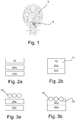
- Figure 1 shows the outline of a drainable collecting bag 1 of the type having a foldable outlet and indicating an area 5 of the bag often exposed to failure caused by external forces.
- the area 5 is particularly exposed to such forces, most often excessive tearing, due to a number of factors, such as the fact that a user typically has to unfold the outlet several times every day to empty collected waste into a toilet bowl, and subsequently clean the outlet and fold it back into its closed or folded position.
- the foldable outlet's position as an extremity of the collecting bag inevitably increases the risk that the outlet may be unintentionally pulled or get entangled with e.g. the clothes of a user, when the outlet is its unfolded position.
- the risk of failure caused by such external forces is significantly reduced or eliminated.
- Figure 2a shows a schematic illustration of the relevant materials of a collecting bag according to the prior art in the production step prior to the welding process.
- Two separate layers of barrier film material 20a and 20b are provided next to each other and a single layer of a non-woven based comfort layer material 10 is provided on top of the layer 20a.
- Figure 2b schematically shows the same materials as in figure 2a after the welding process step.
- the materials 10, 20a, 20b have been bonded together by the heat applied by the welding process.
- the heat may be applied from one single side of the laminate construction, e.g. from the side of the comfort layer 10, or from both sides of the laminate, e.g. both from the side of the comfort layer 10 and from the side of the barrier film layer 20b.
- the figure illustrates how all three layers have been bonded together by melting the material of the layers into a coherent mass, the dotted line 11 representing that the engaging surfaces of the layers are no longer individually distinct.
- the heat provided by the welding process has melted the barrier film material 20a and 20b, but has also melted the (random) fibre structure of the non-woven material 10 whereby the welding zone hardens when it cools off and thus has no or only very little resistance towards external forces left, and is particularly prone to the creation of notches.
- Figure 3a is similar to figure 2a , only here the material of the comfort layer is no longer non-woven based, but instead a textile comfort layer according to the invention.
- the textile is schematically represented by three circles 15 intended to illustrate individual threads of the textile comfort layer.
- each individual thread comprises a higher number of fibre filaments (not shown) per thread but for the sake of simplicity, the principle of the invention is shown only by way of threads and in the figure limited to three threads. Any interlaced threads of the cross-direction of the textile are also not shown in the figure.
- Figure 3b is similar to figure 2b , but schematically illustrates how the threads 15, each comprising a number of individual fibre filaments of the textile comfort layer, are at least partly physically anchored (illustrated by example at position 16) in the melted barrier film material 20a and 20b, as the melted barrier film material flows into the structure of the threads in the textile comfort layer material without melting the fibre structure of the threads.
- the threads 15 of the textile material are not melted, as the textile material has a higher melting point than that of the barrier film. In reality, the melted barrier film material will flow in between the individual fibre filaments of each thread.
- the resulting surface of attachment between the fibre filaments and the barrier film material is significant and thereby the textile comfort layer 15 and the barrier film materials 20a, 20b are laminated to each other such that the peel strength between the barrier film material and the comfort layer is on par with that between a barrier film material and a non-woven based comfort layer, while achieving an improved resistance against external forces, such as tear forces resulting in the creation of notches.
- Figure 4 is a print-out photo of a 250-times magnification of the laminated textile comfort layer and barrier film in the welding zone of a sample collecting bag according to the invention.
- the photo shows how the schematically illustrated ( figure 3b ) principles of the invention are implemented in practice.
- the figure shows how some of the individual fibre filaments 17 of the threads 15 ( Fig. 3b ) of the textile comfort layer have been physically anchored in the melted barrier film mass 20, and also shows that not all of the fibre filaments 18 are embedded.
- the number of individual threads, and thus also the number of fibre filaments, is much higher than in the schematic figure 3a .
- fibre filaments 19 of the interlaced threads of the cross-direction can be observed.
- Some fibre filaments 17 are completely embedded in the melted material 20, whereas others are only partly 21 or not at all 18 embedded in the melted material.
- the melted barrier film material has flowed into the space or spaces between the individual fibre filaments of the threads and the resulting surface of attachment between the fibre filaments and the barrier film material becomes significant.
- the textile comfort layer 15 and the barrier film material 20a, 20b are laminated to each other such that the peel strength between the barrier film material and the comfort layer is surprisingly high.
- the fact that some filaments 18 are free from contact with the melted material 20 provides another advantage of the present invention in that a much less visible and indeed softer welding zone or area is achieved compared to collecting bags with non-woven comfort layers.
- the provision of the free (not melt-embedded) filaments of the textile comfort layer in practice means that, to the naked eye at least, there is no visible difference between the surface characteristics of the comfort layer in the welding zone and anywhere else on the surface of the comfort layer.
- the tactile feel and/or characteristics of the attachment or welding zone of a collecting bag according to the invention is also softer and less rigid than in the case of a non-woven comfort layer and is the same, or at least experienced the same by an individual, as anywhere else on the surface of the comfort layer.
- the layers outside the surfaces of the textile comfort layer in figure 4 are parts of a tool holding the sample in place during the test. It should be noted that for the test preparation, the sample of figure 4 was put into liquid nitrogen before cutting the cross-section out of sample, as cutting the sample at room temperature causes the textile and the barrier film material to be "mashed" into each other.
- the peel strength between a comfort layer and the barrier film material of a collecting bag was measured to show that for a textile based comfort layer according to the invention said peel strength is on par with that of a collecting bag having a traditional non-woven comfort layer attached to the barrier film.
- Test samples included test specimens having a non-woven comfort layer attached to a SaranEX 630G barrier film material from Dow Europe and test specimens having a textile material comfort layer (approx. parameters: weight 71 g/m 2 , yarn number 100 dtex (warp) and 94 dtex (weft) & thread density 40 threads/cm (warp) and 32 threads/cm (weft)) attached to a Nexcel MF513 barrier film material from SealedAir.
- the peel strength test may be carried out either on a texture analyser, e.g. model L500X-8945 from Lloyd or model 5543 from Instron using a 50N load cell and under normal room conditions. Table 1 below shows results obtained with the texture analyser model from Instron. The tensile strength speed (or peel speed) was set to 200mm/min.
- Test procedure includes cutting a sample of the bag (test specimen) perpendicular to the attachment zone or welding 12,5 mm wide on a length of 10cm.
- the holding fixtures (or jaws) holding the sample are fixed to the texture analyser, and the sample is set parallel to the pull direction. Further directions to the test can be found below for the notch sensitivity example.
- Table 1 shows average measured values in [N/12.5mm width].
- Table 1 Comfort layer/Barrier film Non-woven Textile Saran EX 630G 8.189 Nexcel MF513 7.898
- the peel strength using a textile based comfort layer according to the invention is found to be on par with the peel strength, when using a non-woven comfort layer.
- Test samples included 10 test specimens having a non-woven comfort layer (polypropylene spun bond, 30 g/m 2 ) and 10 test specimens having a textile comfort layer according to the invention.
- 10 test specimens included 10 test specimens having a non-woven comfort layer (polypropylene spun bond, 30 g/m 2 ) and 10 test specimens having a textile comfort layer according to the invention.
- 5 specimens were laminated on to a SaranEX 630G barrier film material from Dow Europe and 5 specimens were laminated on to a Nexcel MF513 barrier film material from SealedAir. All test specimens included a single layer of the barrier film material and a single layer of textile material only.
- the tensile stress test was carried out on a texture analyser model 5543 from Instron using a 50N load cell, in an air-conditioned laboratory at a constant temperature of 23° C and at constant 50% RH.
- test specimens were submitted to the tensile stress test by applying the tearing force in a position corresponding to failure area 5 on the collecting bag outlined in figure 1 .
- Each test specimen was mounted in the texture analyser in such a way that the part of the sample adjacent to the left of the tearing force application position was received in a first holding jaw of the texture analyser, and the part adjacent to the right of said position was received in a second holding jaw of the texture analyser.
- the first holding jaw was connected to an actuator capable of providing a force in a lateral upward direction, whereas the second holding jaw was connected to another actuator providing a force in a lateral downward direction.
- Load cells were mounted on the holding jaws to measure the applied force at least at the time of failure. Test results are shown in the below tables 2 and 3.
- Table 2 shows the results of the test for the combination of the non-woven comfort layer mentioned above and the two different barrier film materials from Dow and SealedAir, also described above, respectively.
- Table 3 shows the results of the test for the combination of a textile material according to the invention and the respective barrier film materials mentioned. Table 2 No.
- a collecting bag having a textile comfort layer according to the invention has a significantly higher (more than a factor 2) resistance against failure caused by external forces.
- the test results show that a collecting bag with a textile comfort layer is much less prone to failures caused by tear forces and e.g. the risk of creation of notches in the collecting bag is significantly reduced.
- a collecting bag having a textile comfort layer according to the present invention has on par peel strength characteristics, but a significantly higher resistance to external forces when compared with traditional non-woven material based comfort layers. Also, the collecting bag of the invention is less dependent on the strength of the barrier film itself to resist external forces due to the use of the textile material.
- the present invention provides a collecting bag for human body waste having improved visual and tactile characteristics in the attachment zone(s) between the barrier film material and the comfort layer as supported by the SEM photo of Fig.4 , and further an increased resistance to common wear issues such as snagging and pilling.
Landscapes
- Health & Medical Sciences (AREA)
- General Health & Medical Sciences (AREA)
- Nursing (AREA)
- Animal Behavior & Ethology (AREA)
- Engineering & Computer Science (AREA)
- Biomedical Technology (AREA)
- Heart & Thoracic Surgery (AREA)
- Vascular Medicine (AREA)
- Life Sciences & Earth Sciences (AREA)
- Orthopedic Medicine & Surgery (AREA)
- Epidemiology (AREA)
- Veterinary Medicine (AREA)
- Public Health (AREA)
- Laminated Bodies (AREA)
- Orthopedics, Nursing, And Contraception (AREA)
- Woven Fabrics (AREA)
- Wrappers (AREA)
- Refuse Receptacles (AREA)
- Lining Or Joining Of Plastics Or The Like (AREA)
- Knitting Of Fabric (AREA)
Claims (15)
- Poche de collecte pour des déchets corporels humains comprenant un film barrière (20a, 20b) couvert d'une couche de confort (10), la couche de confort étant un matériau textile possédant un certain nombre de fils (15) comprenant chacun une pluralité de filaments fibreux (17, 18) et le matériau textile étant fixé au matériau de film barrière dans une ou plusieurs zones de fixation,
caractérisée en ce que les fils du matériau textile ont un point de fusion supérieur à celui du matériau de film barrière, et dans laquelle, dans la ou les zones de fixation, une partie, mais pas la totalité des filaments fibreux des fils, est incluse dans le matériau de film barrière. - Poche de collecte selon la revendication 1, dans laquelle la ou les zones de fixation sont formées par le matériau de film barrière qui est conçu pour s'écouler dans des espaces entre les filaments fibreux du matériau textile en réponse à une application de chaleur, dans laquelle le matériau textile est un matériau tissé et dans laquelle chaque fil individuel comprend entre 30 et 150 filaments fibreux individuels.
- Poche de collecte selon la revendication 2, dans laquelle les filaments fibreux qui ne sont pas inclus dans le matériau de film barrière forment une surface de la couche de confort ayant les mêmes caractéristiques tactiles que la surface de la couche de confort à l'extérieur de la ou des zones de fixation.
- Poche de collecte selon la revendication 3, dans laquelle les filaments fibreux qui ne sont pas inclus dans le matériau de film barrière forment une surface de la couche de confort ayant les mêmes caractéristiques visuelles que la surface de la couche de confort à l'extérieur de la ou des zones de fixation.
- Poche de collecte selon l'une quelconque des revendications précédentes, dans laquelle le matériau textile est en fibres synthétiques.
- Poche de collecte selon la revendication 5, dans laquelle les fibres synthétiques sont des fibres de polyester.
- Poche de collecte selon la revendication 2, dans laquelle le poids du matériau textile est dans la plage de 40 à 100 g/m2.
- Poche de collecte selon la revendication 2, dans laquelle le titre du fil du matériau textile est dans la plage de 50 à 120 dtex.
- Poche de collecte selon la revendication 2, dans laquelle la densité de fil du matériau textile est dans la plage de 30 à 50 fils/cm.
- Poche de collecte selon l'une quelconque des revendications 1 à 9, dans laquelle l'épaisseur du matériau textile est dans la plage de 100 à 1 000 µm.
- Poche de collecte selon l'une quelconque des revendications 1 à 10, dans laquelle l'épaisseur du film barrière est dans la plage de 60 à 300 µm.
- Poche de collecte selon l'une quelconque des revendications 1 à 11, la poche de collecte étant une poche de stomie fixée en permanence à un côté d'une plaque de base de stomie.
- Poche de collecte selon l'une quelconque des revendications 1 à 11, la poche de collecte étant une poche de stomie comprenant des premiers moyens d'accouplement pour une mise en prise avec des seconds moyens d'accouplement correspondants sur une plaque de base de stomie.
- Procédé de fabrication d'une poche de collecte pour déchets corporels humains selon la revendication 1, ledit procédé comportant les étapes consistant à :- fournir un matériau de film barrière de la poche de collecte,- fournir un matériau de couche de confort en textile possédant un point de fusion supérieur à celui du matériau de film barrière sur ledit film barrière,- appliquer de la chaleur aux matériaux par un processus de soudage à une pression de processus spécifiée et à une température qui fond le matériau de film barrière, mais pas le matériau textile, de sorte qu'une partie, mais pas la totalité, des filaments fibreux des fils de ladite couche de confort en textile soit entièrement ou partiellement incluse dans ledit matériau de film barrière fondu à l'endroit où le matériau textile et le matériau barrière sont solidaires l'un de l'autre.
- Procédé selon la revendication 14, dans lequel le matériau de couche de confort en textile et le matériau de film barrière sont disposés l'un sur/sous l'autre et parallèlement entre eux.
Priority Applications (1)
| Application Number | Priority Date | Filing Date | Title |
|---|---|---|---|
| EP19193558.4A EP3662873A1 (fr) | 2012-05-25 | 2013-05-17 | Couche de confort pour une poche de collecte |
Applications Claiming Priority (3)
| Application Number | Priority Date | Filing Date | Title |
|---|---|---|---|
| DKPA201270279 | 2012-05-25 | ||
| PCT/DK2013/050150 WO2013174382A1 (fr) | 2012-05-25 | 2013-05-17 | Couche de confort pour une poche de collecte |
| EP13728310.7A EP2854723B1 (fr) | 2012-05-25 | 2013-05-17 | Couche de confort pour une poche de collecte |
Related Parent Applications (2)
| Application Number | Title | Priority Date | Filing Date |
|---|---|---|---|
| EP13728310.7A Division EP2854723B1 (fr) | 2012-05-25 | 2013-05-17 | Couche de confort pour une poche de collecte |
| EP13728310.7A Division-Into EP2854723B1 (fr) | 2012-05-25 | 2013-05-17 | Couche de confort pour une poche de collecte |
Related Child Applications (1)
| Application Number | Title | Priority Date | Filing Date |
|---|---|---|---|
| EP19193558.4A Division EP3662873A1 (fr) | 2012-05-25 | 2013-05-17 | Couche de confort pour une poche de collecte |
Publications (2)
| Publication Number | Publication Date |
|---|---|
| EP3254647A1 EP3254647A1 (fr) | 2017-12-13 |
| EP3254647B1 true EP3254647B1 (fr) | 2019-08-28 |
Family
ID=48613385
Family Applications (3)
| Application Number | Title | Priority Date | Filing Date |
|---|---|---|---|
| EP13728310.7A Revoked EP2854723B1 (fr) | 2012-05-25 | 2013-05-17 | Couche de confort pour une poche de collecte |
| EP19193558.4A Withdrawn EP3662873A1 (fr) | 2012-05-25 | 2013-05-17 | Couche de confort pour une poche de collecte |
| EP17173921.2A Revoked EP3254647B1 (fr) | 2012-05-25 | 2013-05-17 | Couche de confort pour une poche de collecte |
Family Applications Before (2)
| Application Number | Title | Priority Date | Filing Date |
|---|---|---|---|
| EP13728310.7A Revoked EP2854723B1 (fr) | 2012-05-25 | 2013-05-17 | Couche de confort pour une poche de collecte |
| EP19193558.4A Withdrawn EP3662873A1 (fr) | 2012-05-25 | 2013-05-17 | Couche de confort pour une poche de collecte |
Country Status (14)
| Country | Link |
|---|---|
| US (3) | US10045878B2 (fr) |
| EP (3) | EP2854723B1 (fr) |
| JP (3) | JP2015523872A (fr) |
| CN (1) | CN104334126B (fr) |
| AU (2) | AU2013265772B2 (fr) |
| BR (1) | BR112014028447A2 (fr) |
| CA (1) | CA2874284C (fr) |
| DK (2) | DK2854723T3 (fr) |
| ES (2) | ES2753615T3 (fr) |
| HU (2) | HUE033712T2 (fr) |
| IN (1) | IN2014DN09670A (fr) |
| PL (1) | PL2854723T3 (fr) |
| RU (1) | RU2634670C2 (fr) |
| WO (1) | WO2013174382A1 (fr) |
Families Citing this family (17)
| Publication number | Priority date | Publication date | Assignee | Title |
|---|---|---|---|---|
| MX2009013331A (es) | 2007-06-12 | 2010-01-25 | Convatec Technologies Inc | Aparato de ostomia. |
| RU2519961C2 (ru) | 2008-11-19 | 2014-06-20 | Конватек Текнолоджиз Инк. | Стомное приспособление с мешком |
| CA2766120C (fr) | 2009-07-07 | 2018-08-14 | Convatec Technologies Inc. | Copolymeres de silicone amphiphiles pour applications autoadhesives |
| US8845606B2 (en) | 2009-09-11 | 2014-09-30 | Convatec Technologies Inc. | Controlled discharge ostomy appliance and shield therefor |
| US10285847B2 (en) | 2011-09-29 | 2019-05-14 | Convatec Technologies Inc. | Ostomy pouch with filtering system |
| GB201115160D0 (en) | 2011-09-02 | 2011-10-19 | Trio Healthcare Ltd | Discharge solidifier and malodour control |
| DK2854723T3 (en) | 2012-05-25 | 2017-10-16 | Coloplast As | COMFORT FOR A COLLECTION BAG |
| MX2016013987A (es) | 2014-04-24 | 2017-01-11 | Convatec Technologies Inc | Sistema de filtro de bolsa de ostomia. |
| CA3002013C (fr) | 2015-10-14 | 2024-02-27 | Convatec Technologies Inc. | Un appareil medical dote d'un systeme d'ouverture |
| MX2020004744A (es) | 2017-11-09 | 2020-08-13 | 11 Health And Tech Limited | Sistema y metodo de monitoreo de ostomia. |
| LT3713632T (lt) | 2017-11-20 | 2024-05-27 | Hollister Incorporated | Šlapimo kateterio rinkiniai, apimantys pakuotę |
| USD893514S1 (en) | 2018-11-08 | 2020-08-18 | 11 Health And Technologies Limited | Display screen or portion thereof with graphical user interface |
| EP3692956A1 (fr) | 2019-02-07 | 2020-08-12 | ConvaTec Technologies Inc. | Dispositif stomique réglable convexe |
| EP3949993A4 (fr) | 2019-03-28 | 2023-07-05 | Waseda University | Inhibiteur de compétition cellulaire |
| JP7458416B2 (ja) | 2019-04-25 | 2024-03-29 | コンバテック・テクノロジーズ・インコーポレイテッド | 接着剤を組み込んだオストミーウェハ、オストミーウェハを含むオストミー装置、及びオストミーウェハとオストミー装置の接触方法 |
| US11638658B2 (en) | 2019-04-25 | 2023-05-02 | Convatec Technologies, Inc. | Ostomy wafers incorporating adhesives and foam layers, ostomy devices including the same, and methods of applying ostomy wafers and ostomy devices |
| CA3137966A1 (fr) | 2019-04-25 | 2020-10-29 | Convatec Technologies Inc. | Plaquettes de stomie a chambre perforee, dispositifs les comprenant, et procedes d'utilisation |
Citations (6)
| Publication number | Priority date | Publication date | Assignee | Title |
|---|---|---|---|---|
| GB2064333A (en) | 1979-12-10 | 1981-06-17 | Searle & Co | Ostomy device |
| US5800928A (en) | 1994-06-20 | 1998-09-01 | Elf Atochem S.A. | Breathable waterproof film |
| WO2002094143A1 (fr) | 2001-05-21 | 2002-11-28 | Coloplast A/S | Accessoire pour stomie |
| WO2005041827A2 (fr) | 2003-10-21 | 2005-05-12 | Hollister Incorporated | Poche de collecte de dechets corporels jetable, dispositif poche dans poche utilisant ladite poche et procede associe |
| US20050273064A1 (en) | 2004-06-04 | 2005-12-08 | Dircks Lon E | Laminated material and body wearable pouch formed therefrom |
| WO2008112337A1 (fr) | 2007-03-13 | 2008-09-18 | Hollister Incorporated | Produit destiné à être porté au contact de la peau et procédé de fabrication d'un tel produit |
Family Cites Families (43)
| Publication number | Priority date | Publication date | Assignee | Title |
|---|---|---|---|---|
| US4439191A (en) * | 1982-07-14 | 1984-03-27 | Hogan Elizabeth R | Ostomy bag cover |
| US4728323A (en) * | 1986-07-24 | 1988-03-01 | Minnesota Mining And Manufacturing Company | Antimicrobial wound dressings |
| GB2216007B (en) * | 1988-03-28 | 1992-09-02 | Squibb & Sons Inc | Ileostomy appliance |
| GB2239838B (en) | 1989-12-13 | 1994-05-18 | Grace W R & Co | Improved film |
| US5250042A (en) * | 1990-02-20 | 1993-10-05 | E. R. Squibb & Sons, Inc. | Ostomy bag with filter combination |
| JP2540842Y2 (ja) * | 1991-02-06 | 1997-07-09 | アルケア株式会社 | オストミーバッグ |
| US5403299A (en) * | 1994-01-18 | 1995-04-04 | Hollister Incorporated | Flush-interval indicator for soluble pouches |
| GB2287193A (en) | 1994-03-07 | 1995-09-13 | Squibb & Sons Inc | Manufacture of ostomy bag having associated filter |
| US6861570B1 (en) * | 1997-09-22 | 2005-03-01 | A. Bart Flick | Multilayer conductive appliance having wound healing and analgesic properties |
| US5759180A (en) * | 1997-01-27 | 1998-06-02 | Myhres; Donita F. | Ostomy bag cover and assembly |
| AU742004B2 (en) * | 1997-04-08 | 2001-12-13 | Coloplast A/S | An ostomy appliance |
| GB2351238B (en) * | 1998-08-13 | 2001-10-24 | Bristol Myers Squibb Co | Adhesive wafer for ostomy pouch |
| JP2000111987A (ja) | 1998-09-30 | 2000-04-21 | Fuji Photo Optical Co Ltd | カメラの電池蓋構造 |
| GB0029030D0 (en) | 2000-11-28 | 2001-01-10 | Smiths Group Plc | WC-diposable articles |
| DK174693B1 (da) | 2001-06-15 | 2003-09-15 | Coloplast As | Stormiindretning |
| DK175870B1 (da) | 2001-09-05 | 2005-05-02 | Coloplast As | Stomiindretning |
| DK174792B1 (da) | 2001-09-07 | 2003-11-24 | Coloplast As | Emballage til en stomiindretning |
| FR2839883B1 (fr) * | 2002-05-21 | 2005-02-25 | Braun Medical | Poche de recueil de fluides corporels munie d'un dispositif d'ouverture et de fermeture d'un canal d'evacuation |
| RU2220685C1 (ru) | 2002-06-25 | 2004-01-10 | Общество с ограниченной ответственностью "Пальма" | Приемник для сбора выделений из стомы |
| GB2391175B (en) | 2002-07-04 | 2005-12-28 | Bristol Myers Squibb Co | Pouch for collecting human waste |
| DK176261B1 (da) | 2003-02-04 | 2007-05-07 | Coloplast As | Emballage til stomiindretning |
| US20040204694A1 (en) * | 2003-04-10 | 2004-10-14 | Nicholson Micheal E. | Device and method of reducing friction and displacement of ostomy appliances |
| DK1633292T3 (da) * | 2003-06-02 | 2010-06-07 | Hollister Inc | Klæbende frontplade til stomiindretning |
| DK176027B1 (da) * | 2003-12-22 | 2005-12-19 | Hollister Inc | Stomiindretning med forfilter |
| DK1684679T3 (da) * | 2003-10-21 | 2009-10-12 | Hollister Inc | Skrælbar og gennemskyllelig stomipose og anvendelsesområde |
| ATE498378T1 (de) * | 2003-10-21 | 2011-03-15 | Hollister Inc | Spülbarer körperschlacken-auffangbeutel und diesen verwendende beutel/beutel-vorrichtung |
| US8449511B2 (en) | 2004-09-08 | 2013-05-28 | Coloplast A/S | Activity ostomy bag |
| CA2625268C (fr) * | 2005-11-28 | 2014-01-28 | Hollister Incorporated | Ameliorations concernant des poches jetables dans les toilettes destinees a la collecte d'echantillons corporels, dispositifs poche dans poche utilisant lesdites poches et procedes associes |
| DK2007331T3 (en) | 2006-04-11 | 2017-06-19 | Coloplast As | COLLECTION BAG WITH IMPROVED CLOSING AND PROCEDURE FOR PREPARING SUCH A COLLECTION BAG |
| US20080033379A1 (en) | 2006-04-29 | 2008-02-07 | Pedersen Jes L | Drainable ostomy pouch with bias members and closure means |
| EP2853245A1 (fr) | 2006-12-20 | 2015-04-01 | Coloplast A/S | Composition adhésive sensible à la pression comprenant du sel |
| DK2240148T3 (da) | 2008-02-13 | 2013-02-18 | Filag Schweiz Ag | Hydrofil hudplejeklud |
| CA2720463C (fr) | 2008-04-04 | 2016-03-29 | Convatec Technologies Inc. | Poche de stomie vidangeable |
| EP2108345A1 (fr) | 2008-04-11 | 2009-10-14 | Eurotec Beheer B.V. | Système de stomie à pièce unique avec une ouverture de stomie extensible et souple |
| JP4492887B2 (ja) | 2008-10-08 | 2010-06-30 | 圭 清水 | 水溶性の織物又は編み物、その製造方法および水溶性の糸 |
| GB2473206B (en) | 2009-09-02 | 2014-12-17 | Welland Medical Ltd | A flushable ostomy bag having an outer protective and inner waste collecting pouch |
| GB2473044B (en) * | 2009-08-28 | 2014-05-14 | Welland Medical Ltd | A process for manufacturing an ostomy bag |
| US20110289923A1 (en) * | 2010-05-26 | 2011-12-01 | Separation Technologies Llc | Recovery of mercury control reagents by tribo-electric separation |
| EP2797993A4 (fr) | 2011-12-28 | 2015-12-09 | Hollister Inc | Matériau non tissé insonorisant, film multicouche insonorisant et leurs stratifiés fabriqués |
| DK2854723T3 (en) | 2012-05-25 | 2017-10-16 | Coloplast As | COMFORT FOR A COLLECTION BAG |
| US10105254B2 (en) * | 2012-10-23 | 2018-10-23 | Coloplast A/S | Blow-moulding of ostomy bags |
| US9050387B2 (en) | 2013-02-07 | 2015-06-09 | Hollister Incorporated | Sound absorbing ostomy pouch |
| FR3008880B1 (fr) | 2013-07-25 | 2015-09-04 | Commissariat Energie Atomique | Dispositif de mesure de la perte hydrique |
-
2013
- 2013-05-17 DK DK13728310.7T patent/DK2854723T3/en active
- 2013-05-17 RU RU2014152797A patent/RU2634670C2/ru active
- 2013-05-17 ES ES17173921T patent/ES2753615T3/es active Active
- 2013-05-17 ES ES13728310.7T patent/ES2641391T3/es active Active
- 2013-05-17 EP EP13728310.7A patent/EP2854723B1/fr not_active Revoked
- 2013-05-17 CN CN201380026097.7A patent/CN104334126B/zh not_active Expired - Fee Related
- 2013-05-17 BR BR112014028447A patent/BR112014028447A2/pt not_active Application Discontinuation
- 2013-05-17 JP JP2015513021A patent/JP2015523872A/ja not_active Withdrawn
- 2013-05-17 PL PL13728310T patent/PL2854723T3/pl unknown
- 2013-05-17 EP EP19193558.4A patent/EP3662873A1/fr not_active Withdrawn
- 2013-05-17 HU HUE13728310A patent/HUE033712T2/en unknown
- 2013-05-17 AU AU2013265772A patent/AU2013265772B2/en not_active Revoked
- 2013-05-17 US US14/402,692 patent/US10045878B2/en active Active
- 2013-05-17 EP EP17173921.2A patent/EP3254647B1/fr not_active Revoked
- 2013-05-17 WO PCT/DK2013/050150 patent/WO2013174382A1/fr active Application Filing
- 2013-05-17 HU HUE17173921A patent/HUE045816T2/hu unknown
- 2013-05-17 DK DK17173921T patent/DK3254647T3/da active
- 2013-05-17 IN IN9670DEN2014 patent/IN2014DN09670A/en unknown
- 2013-05-17 CA CA2874284A patent/CA2874284C/fr not_active Expired - Fee Related
-
2017
- 2017-06-01 AU AU2017203705A patent/AU2017203705B2/en not_active Revoked
-
2018
- 2018-06-12 US US16/005,708 patent/US10973677B2/en active Active
-
2019
- 2019-01-10 JP JP2019002754A patent/JP2019063594A/ja active Pending
-
2021
- 2021-01-27 JP JP2021011142A patent/JP2021087791A/ja not_active Withdrawn
- 2021-02-04 US US17/167,114 patent/US11617675B2/en active Active
Patent Citations (6)
| Publication number | Priority date | Publication date | Assignee | Title |
|---|---|---|---|---|
| GB2064333A (en) | 1979-12-10 | 1981-06-17 | Searle & Co | Ostomy device |
| US5800928A (en) | 1994-06-20 | 1998-09-01 | Elf Atochem S.A. | Breathable waterproof film |
| WO2002094143A1 (fr) | 2001-05-21 | 2002-11-28 | Coloplast A/S | Accessoire pour stomie |
| WO2005041827A2 (fr) | 2003-10-21 | 2005-05-12 | Hollister Incorporated | Poche de collecte de dechets corporels jetable, dispositif poche dans poche utilisant ladite poche et procede associe |
| US20050273064A1 (en) | 2004-06-04 | 2005-12-08 | Dircks Lon E | Laminated material and body wearable pouch formed therefrom |
| WO2008112337A1 (fr) | 2007-03-13 | 2008-09-18 | Hollister Incorporated | Produit destiné à être porté au contact de la peau et procédé de fabrication d'un tel produit |
Non-Patent Citations (4)
| Title |
|---|
| ANONYMOUS: "Coloplast introduces the "Yes, you can" ostomy system", JOURNAL OF ENTEROSTOMAL THERAPY, May 1984 (1984-05-01), pages 1 - 3, XP055605496 |
| ANONYMOUS: "COLOPLAST", NURSING TIMES, 30 May 1984 (1984-05-30), pages 1 - 3, XP055605499 |
| ANONYMOUS: "The Coloplast mc2002 Ostomy system", COLOPLAST, 1 March 1984 (1984-03-01), Tampa, Florida, USA, XP055605510 |
| ANONYMOUS: "The Coloplast mc2002", COLOPLAST BROCHURE, 1 March 1984 (1984-03-01), XP055605513 |
Also Published As
Similar Documents
| Publication | Publication Date | Title |
|---|---|---|
| US11617675B2 (en) | Ostomy bag having a textile layer bonded to a barrier film along a portion of an outer periphery of the ostomy bag | |
| JP5148601B2 (ja) | 吸収性物品用伸縮性外側カバー及びその製造プロセス | |
| JP5551733B2 (ja) | マルチ構造ラミネート用の接着促進剤 | |
| US20080294129A1 (en) | Flushable Body Waste Collection Pouches, Pouch-in Pouch Appliances Using the Same, and Methods Pertaining Thereto | |
| CN102665618B (zh) | 一次性造口袋 | |
| WO2015092569A1 (fr) | Matériaux élastiques rainurés post-liés | |
| MX2007011921A (es) | Metodo para producir telas degradables en agua y/o elasticas a partir de filamentos compuestos. | |
| CN1379799A (zh) | 低应力松驰弹性体材料 | |
| CN1217788C (zh) | 辐射状交联的弹性体材料 | |
| CA2813544A1 (fr) | Stratifies colles par extrusion pour articles absorbants | |
| JP3380701B2 (ja) | 多孔質袋体、これを用いた発熱体、脱酸素体、脱臭体、追熟体、乾燥材、除湿材及び匂い袋 | |
| JP2002249972A (ja) | メルトブロー不織布 | |
| WO2020131747A1 (fr) | Formation de motifs sur un stratifié élastique | |
| BR112016012919B1 (pt) | Método de formação de um laminado elástico não tecido, laminado não tecido elástico, e, artigo absorvente | |
| AU5184201A (en) | Method of heat sealing adhesive bandage and adhesive bandage made by using said method | |
| MXPA01001196A (en) | Laminate having barrier properties |
Legal Events
| Date | Code | Title | Description |
|---|---|---|---|
| PUAI | Public reference made under article 153(3) epc to a published international application that has entered the european phase |
Free format text: ORIGINAL CODE: 0009012 |
|
| STAA | Information on the status of an ep patent application or granted ep patent |
Free format text: STATUS: THE APPLICATION HAS BEEN PUBLISHED |
|
| AC | Divisional application: reference to earlier application |
Ref document number: 2854723 Country of ref document: EP Kind code of ref document: P |
|
| AK | Designated contracting states |
Kind code of ref document: A1 Designated state(s): AL AT BE BG CH CY CZ DE DK EE ES FI FR GB GR HR HU IE IS IT LI LT LU LV MC MK MT NL NO PL PT RO RS SE SI SK SM TR |
|
| STAA | Information on the status of an ep patent application or granted ep patent |
Free format text: STATUS: REQUEST FOR EXAMINATION WAS MADE |
|
| 17P | Request for examination filed |
Effective date: 20180606 |
|
| RBV | Designated contracting states (corrected) |
Designated state(s): AL AT BE BG CH CY CZ DE DK EE ES FI FR GB GR HR HU IE IS IT LI LT LU LV MC MK MT NL NO PL PT RO RS SE SI SK SM TR |
|
| GRAP | Despatch of communication of intention to grant a patent |
Free format text: ORIGINAL CODE: EPIDOSNIGR1 |
|
| STAA | Information on the status of an ep patent application or granted ep patent |
Free format text: STATUS: GRANT OF PATENT IS INTENDED |
|
| RIC1 | Information provided on ipc code assigned before grant |
Ipc: A61F 5/445 20060101AFI20180919BHEP Ipc: B31B 70/00 20170101ALN20180919BHEP Ipc: A61F 5/44 20060101ALN20180919BHEP |
|
| INTG | Intention to grant announced |
Effective date: 20181008 |
|
| RIN1 | Information on inventor provided before grant (corrected) |
Inventor name: FREIDING, MARKUS |
|
| GRAJ | Information related to disapproval of communication of intention to grant by the applicant or resumption of examination proceedings by the epo deleted |
Free format text: ORIGINAL CODE: EPIDOSDIGR1 |
|
| STAA | Information on the status of an ep patent application or granted ep patent |
Free format text: STATUS: REQUEST FOR EXAMINATION WAS MADE |
|
| GRAP | Despatch of communication of intention to grant a patent |
Free format text: ORIGINAL CODE: EPIDOSNIGR1 |
|
| STAA | Information on the status of an ep patent application or granted ep patent |
Free format text: STATUS: GRANT OF PATENT IS INTENDED |
|
| INTC | Intention to grant announced (deleted) | ||
| RIC1 | Information provided on ipc code assigned before grant |
Ipc: B31B 70/00 20170101ALN20190124BHEP Ipc: A61F 5/44 20060101ALN20190124BHEP Ipc: A61F 5/445 20060101AFI20190124BHEP |
|
| INTG | Intention to grant announced |
Effective date: 20190215 |
|
| TPAC | Observations filed by third parties |
Free format text: ORIGINAL CODE: EPIDOSNTIPA |
|
| GRAS | Grant fee paid |
Free format text: ORIGINAL CODE: EPIDOSNIGR3 |
|
| TPAC | Observations filed by third parties |
Free format text: ORIGINAL CODE: EPIDOSNTIPA |
|
| GRAA | (expected) grant |
Free format text: ORIGINAL CODE: 0009210 |
|
| STAA | Information on the status of an ep patent application or granted ep patent |
Free format text: STATUS: THE PATENT HAS BEEN GRANTED |
|
| TPAC | Observations filed by third parties |
Free format text: ORIGINAL CODE: EPIDOSNTIPA |
|
| AC | Divisional application: reference to earlier application |
Ref document number: 2854723 Country of ref document: EP Kind code of ref document: P |
|
| AK | Designated contracting states |
Kind code of ref document: B1 Designated state(s): AL AT BE BG CH CY CZ DE DK EE ES FI FR GB GR HR HU IE IS IT LI LT LU LV MC MK MT NL NO PL PT RO RS SE SI SK SM TR |
|
| REG | Reference to a national code |
Ref country code: GB Ref legal event code: FG4D |
|
| REG | Reference to a national code |
Ref country code: CH Ref legal event code: EP |
|
| REG | Reference to a national code |
Ref country code: AT Ref legal event code: REF Ref document number: 1171452 Country of ref document: AT Kind code of ref document: T Effective date: 20190915 |
|
| REG | Reference to a national code |
Ref country code: IE Ref legal event code: FG4D |
|
| REG | Reference to a national code |
Ref country code: DE Ref legal event code: R096 Ref document number: 602013059910 Country of ref document: DE |
|
| REG | Reference to a national code |
Ref country code: DK Ref legal event code: T3 Effective date: 20191127 |
|
| REG | Reference to a national code |
Ref country code: NL Ref legal event code: FP |
|
| REG | Reference to a national code |
Ref country code: SE Ref legal event code: TRGR |
|
| REG | Reference to a national code |
Ref country code: NO Ref legal event code: CREP Representative=s name: TANDBERG INNOVATION AS, POSTBOKS 1570 VIKA, 0118 Ref country code: NO Ref legal event code: T2 Effective date: 20190828 |
|
| REG | Reference to a national code |
Ref country code: LT Ref legal event code: MG4D |
|
| REG | Reference to a national code |
Ref country code: HU Ref legal event code: AG4A Ref document number: E045816 Country of ref document: HU |
|
| PG25 | Lapsed in a contracting state [announced via postgrant information from national office to epo] |
Ref country code: LT Free format text: LAPSE BECAUSE OF FAILURE TO SUBMIT A TRANSLATION OF THE DESCRIPTION OR TO PAY THE FEE WITHIN THE PRESCRIBED TIME-LIMIT Effective date: 20190828 Ref country code: PT Free format text: LAPSE BECAUSE OF FAILURE TO SUBMIT A TRANSLATION OF THE DESCRIPTION OR TO PAY THE FEE WITHIN THE PRESCRIBED TIME-LIMIT Effective date: 20191230 Ref country code: HR Free format text: LAPSE BECAUSE OF FAILURE TO SUBMIT A TRANSLATION OF THE DESCRIPTION OR TO PAY THE FEE WITHIN THE PRESCRIBED TIME-LIMIT Effective date: 20190828 Ref country code: BG Free format text: LAPSE BECAUSE OF FAILURE TO SUBMIT A TRANSLATION OF THE DESCRIPTION OR TO PAY THE FEE WITHIN THE PRESCRIBED TIME-LIMIT Effective date: 20191128 |
|
| PG25 | Lapsed in a contracting state [announced via postgrant information from national office to epo] |
Ref country code: RS Free format text: LAPSE BECAUSE OF FAILURE TO SUBMIT A TRANSLATION OF THE DESCRIPTION OR TO PAY THE FEE WITHIN THE PRESCRIBED TIME-LIMIT Effective date: 20190828 Ref country code: LV Free format text: LAPSE BECAUSE OF FAILURE TO SUBMIT A TRANSLATION OF THE DESCRIPTION OR TO PAY THE FEE WITHIN THE PRESCRIBED TIME-LIMIT Effective date: 20190828 Ref country code: AL Free format text: LAPSE BECAUSE OF FAILURE TO SUBMIT A TRANSLATION OF THE DESCRIPTION OR TO PAY THE FEE WITHIN THE PRESCRIBED TIME-LIMIT Effective date: 20190828 Ref country code: GR Free format text: LAPSE BECAUSE OF FAILURE TO SUBMIT A TRANSLATION OF THE DESCRIPTION OR TO PAY THE FEE WITHIN THE PRESCRIBED TIME-LIMIT Effective date: 20191129 Ref country code: IS Free format text: LAPSE BECAUSE OF FAILURE TO SUBMIT A TRANSLATION OF THE DESCRIPTION OR TO PAY THE FEE WITHIN THE PRESCRIBED TIME-LIMIT Effective date: 20191228 |
|
| PG25 | Lapsed in a contracting state [announced via postgrant information from national office to epo] |
Ref country code: TR Free format text: LAPSE BECAUSE OF FAILURE TO SUBMIT A TRANSLATION OF THE DESCRIPTION OR TO PAY THE FEE WITHIN THE PRESCRIBED TIME-LIMIT Effective date: 20190828 |
|
| REG | Reference to a national code |
Ref country code: ES Ref legal event code: FG2A Ref document number: 2753615 Country of ref document: ES Kind code of ref document: T3 Effective date: 20200413 |
|
| PG25 | Lapsed in a contracting state [announced via postgrant information from national office to epo] |
Ref country code: EE Free format text: LAPSE BECAUSE OF FAILURE TO SUBMIT A TRANSLATION OF THE DESCRIPTION OR TO PAY THE FEE WITHIN THE PRESCRIBED TIME-LIMIT Effective date: 20190828 Ref country code: PL Free format text: LAPSE BECAUSE OF FAILURE TO SUBMIT A TRANSLATION OF THE DESCRIPTION OR TO PAY THE FEE WITHIN THE PRESCRIBED TIME-LIMIT Effective date: 20190828 Ref country code: RO Free format text: LAPSE BECAUSE OF FAILURE TO SUBMIT A TRANSLATION OF THE DESCRIPTION OR TO PAY THE FEE WITHIN THE PRESCRIBED TIME-LIMIT Effective date: 20190828 |
|
| REG | Reference to a national code |
Ref country code: AT Ref legal event code: UEP Ref document number: 1171452 Country of ref document: AT Kind code of ref document: T Effective date: 20190828 |
|
| REG | Reference to a national code |
Ref country code: DE Ref legal event code: R026 Ref document number: 602013059910 Country of ref document: DE |
|
| PG25 | Lapsed in a contracting state [announced via postgrant information from national office to epo] |
Ref country code: SM Free format text: LAPSE BECAUSE OF FAILURE TO SUBMIT A TRANSLATION OF THE DESCRIPTION OR TO PAY THE FEE WITHIN THE PRESCRIBED TIME-LIMIT Effective date: 20190828 Ref country code: SK Free format text: LAPSE BECAUSE OF FAILURE TO SUBMIT A TRANSLATION OF THE DESCRIPTION OR TO PAY THE FEE WITHIN THE PRESCRIBED TIME-LIMIT Effective date: 20190828 Ref country code: IS Free format text: LAPSE BECAUSE OF FAILURE TO SUBMIT A TRANSLATION OF THE DESCRIPTION OR TO PAY THE FEE WITHIN THE PRESCRIBED TIME-LIMIT Effective date: 20200224 Ref country code: CZ Free format text: LAPSE BECAUSE OF FAILURE TO SUBMIT A TRANSLATION OF THE DESCRIPTION OR TO PAY THE FEE WITHIN THE PRESCRIBED TIME-LIMIT Effective date: 20190828 |
|
| PLBI | Opposition filed |
Free format text: ORIGINAL CODE: 0009260 |
|
| PLBI | Opposition filed |
Free format text: ORIGINAL CODE: 0009260 |
|
| PLAX | Notice of opposition and request to file observation + time limit sent |
Free format text: ORIGINAL CODE: EPIDOSNOBS2 |
|
| REG | Reference to a national code |
Ref country code: FI Ref legal event code: MDE Opponent name: SALTS HEALTHCARE LIMITED Ref country code: FI Ref legal event code: MDE Opponent name: HOLLISTER INCORPORATED |
|
| 26 | Opposition filed |
Opponent name: HOLLISTER INCORPORATED Effective date: 20200522 |
|
| PLAB | Opposition data, opponent's data or that of the opponent's representative modified |
Free format text: ORIGINAL CODE: 0009299OPPO |
|
| REG | Reference to a national code |
Ref country code: FI Ref legal event code: MDE Opponent name: HOLLISTER INCORPORATED Ref country code: FI Ref legal event code: MDE Opponent name: SALTS HEALTHCARE LIMITED |
|
| 26 | Opposition filed |
Opponent name: SALTS HEALTHCARE LIMITED Effective date: 20200601 |
|
| PG2D | Information on lapse in contracting state deleted |
Ref country code: IS |
|
| R26 | Opposition filed (corrected) |
Opponent name: HOLLISTER INCORPORATED Effective date: 20200522 |
|
| PG25 | Lapsed in a contracting state [announced via postgrant information from national office to epo] |
Ref country code: SI Free format text: LAPSE BECAUSE OF FAILURE TO SUBMIT A TRANSLATION OF THE DESCRIPTION OR TO PAY THE FEE WITHIN THE PRESCRIBED TIME-LIMIT Effective date: 20190828 |
|
| PLAB | Opposition data, opponent's data or that of the opponent's representative modified |
Free format text: ORIGINAL CODE: 0009299OPPO |
|
| R26 | Opposition filed (corrected) |
Opponent name: SALTS HEALTHCARE LIMITED Effective date: 20200601 |
|
| PLBB | Reply of patent proprietor to notice(s) of opposition received |
Free format text: ORIGINAL CODE: EPIDOSNOBS3 |
|
| PG25 | Lapsed in a contracting state [announced via postgrant information from national office to epo] |
Ref country code: MC Free format text: LAPSE BECAUSE OF FAILURE TO SUBMIT A TRANSLATION OF THE DESCRIPTION OR TO PAY THE FEE WITHIN THE PRESCRIBED TIME-LIMIT Effective date: 20190828 Ref country code: CH Free format text: LAPSE BECAUSE OF NON-PAYMENT OF DUE FEES Effective date: 20200531 Ref country code: LI Free format text: LAPSE BECAUSE OF NON-PAYMENT OF DUE FEES Effective date: 20200531 |
|
| REG | Reference to a national code |
Ref country code: BE Ref legal event code: MM Effective date: 20200531 |
|
| PG25 | Lapsed in a contracting state [announced via postgrant information from national office to epo] |
Ref country code: LU Free format text: LAPSE BECAUSE OF NON-PAYMENT OF DUE FEES Effective date: 20200517 |
|
| PG25 | Lapsed in a contracting state [announced via postgrant information from national office to epo] |
Ref country code: BE Free format text: LAPSE BECAUSE OF NON-PAYMENT OF DUE FEES Effective date: 20200531 |
|
| PGFP | Annual fee paid to national office [announced via postgrant information from national office to epo] |
Ref country code: FR Payment date: 20210525 Year of fee payment: 9 Ref country code: NO Payment date: 20210527 Year of fee payment: 9 Ref country code: FI Payment date: 20210527 Year of fee payment: 9 Ref country code: DE Payment date: 20210527 Year of fee payment: 9 Ref country code: IT Payment date: 20210524 Year of fee payment: 9 Ref country code: NL Payment date: 20210526 Year of fee payment: 9 |
|
| PGFP | Annual fee paid to national office [announced via postgrant information from national office to epo] |
Ref country code: DK Payment date: 20210527 Year of fee payment: 9 Ref country code: ES Payment date: 20210601 Year of fee payment: 9 Ref country code: SE Payment date: 20210527 Year of fee payment: 9 Ref country code: AT Payment date: 20210504 Year of fee payment: 9 Ref country code: IE Payment date: 20210527 Year of fee payment: 9 Ref country code: GB Payment date: 20210527 Year of fee payment: 9 Ref country code: HU Payment date: 20210505 Year of fee payment: 9 |
|
| RDAE | Information deleted related to despatch of communication that patent is revoked |
Free format text: ORIGINAL CODE: EPIDOSDREV1 |
|
| RDAF | Communication despatched that patent is revoked |
Free format text: ORIGINAL CODE: EPIDOSNREV1 |
|
| REG | Reference to a national code |
Ref country code: DE Ref legal event code: R103 Ref document number: 602013059910 Country of ref document: DE Ref country code: DE Ref legal event code: R064 Ref document number: 602013059910 Country of ref document: DE |
|
| RDAG | Patent revoked |
Free format text: ORIGINAL CODE: 0009271 |
|
| STAA | Information on the status of an ep patent application or granted ep patent |
Free format text: STATUS: PATENT REVOKED |
|
| REG | Reference to a national code |
Ref country code: CH Ref legal event code: PL |
|
| REG | Reference to a national code |
Ref country code: FI Ref legal event code: MGE |
|
| 27W | Patent revoked |
Effective date: 20211007 |
|
| GBPR | Gb: patent revoked under art. 102 of the ep convention designating the uk as contracting state |
Effective date: 20211007 |
|
| REG | Reference to a national code |
Ref country code: AT Ref legal event code: MA03 Ref document number: 1171452 Country of ref document: AT Kind code of ref document: T Effective date: 20211007 |
|
| REG | Reference to a national code |
Ref country code: SE Ref legal event code: ECNC |
|
| PG25 | Lapsed in a contracting state [announced via postgrant information from national office to epo] |
Ref country code: MT Free format text: LAPSE BECAUSE OF FAILURE TO SUBMIT A TRANSLATION OF THE DESCRIPTION OR TO PAY THE FEE WITHIN THE PRESCRIBED TIME-LIMIT Effective date: 20190828 Ref country code: CY Free format text: LAPSE BECAUSE OF FAILURE TO SUBMIT A TRANSLATION OF THE DESCRIPTION OR TO PAY THE FEE WITHIN THE PRESCRIBED TIME-LIMIT Effective date: 20190828 |
|
| PG25 | Lapsed in a contracting state [announced via postgrant information from national office to epo] |
Ref country code: MK Free format text: LAPSE BECAUSE OF FAILURE TO SUBMIT A TRANSLATION OF THE DESCRIPTION OR TO PAY THE FEE WITHIN THE PRESCRIBED TIME-LIMIT Effective date: 20190828 |