EP3254124B1 - Vorrichtung und verfahren zum ermitteln einer kenngrösse eines transformators - Google Patents
Vorrichtung und verfahren zum ermitteln einer kenngrösse eines transformators Download PDFInfo
- Publication number
- EP3254124B1 EP3254124B1 EP16701515.5A EP16701515A EP3254124B1 EP 3254124 B1 EP3254124 B1 EP 3254124B1 EP 16701515 A EP16701515 A EP 16701515A EP 3254124 B1 EP3254124 B1 EP 3254124B1
- Authority
- EP
- European Patent Office
- Prior art keywords
- transformer
- voltage side
- reactance
- leakage
- inductance
- Prior art date
- Legal status (The legal status is an assumption and is not a legal conclusion. Google has not performed a legal analysis and makes no representation as to the accuracy of the status listed.)
- Active
Links
Images


Classifications
-
- G—PHYSICS
- G01—MEASURING; TESTING
- G01R—MEASURING ELECTRIC VARIABLES; MEASURING MAGNETIC VARIABLES
- G01R31/00—Arrangements for testing electric properties; Arrangements for locating electric faults; Arrangements for electrical testing characterised by what is being tested not provided for elsewhere
- G01R31/50—Testing of electric apparatus, lines, cables or components for short-circuits, continuity, leakage current or incorrect line connections
-
- G—PHYSICS
- G01—MEASURING; TESTING
- G01R—MEASURING ELECTRIC VARIABLES; MEASURING MAGNETIC VARIABLES
- G01R27/00—Arrangements for measuring resistance, reactance, impedance, or electric characteristics derived therefrom
- G01R27/02—Measuring real or complex resistance, reactance, impedance, or other two-pole characteristics derived therefrom, e.g. time constant
- G01R27/26—Measuring inductance or capacitance; Measuring quality factor, e.g. by using the resonance method; Measuring loss factor; Measuring dielectric constants ; Measuring impedance or related variables
- G01R27/2611—Measuring inductance
-
- G—PHYSICS
- G01—MEASURING; TESTING
- G01R—MEASURING ELECTRIC VARIABLES; MEASURING MAGNETIC VARIABLES
- G01R31/00—Arrangements for testing electric properties; Arrangements for locating electric faults; Arrangements for electrical testing characterised by what is being tested not provided for elsewhere
- G01R31/50—Testing of electric apparatus, lines, cables or components for short-circuits, continuity, leakage current or incorrect line connections
- G01R31/62—Testing of transformers
-
- H—ELECTRICITY
- H02—GENERATION; CONVERSION OR DISTRIBUTION OF ELECTRIC POWER
- H02H—EMERGENCY PROTECTIVE CIRCUIT ARRANGEMENTS
- H02H7/00—Emergency protective circuit arrangements specially adapted for specific types of electric machines or apparatus or for sectionalised protection of cable or line systems, and effecting automatic switching in the event of an undesired change from normal working conditions
- H02H7/04—Emergency protective circuit arrangements specially adapted for specific types of electric machines or apparatus or for sectionalised protection of cable or line systems, and effecting automatic switching in the event of an undesired change from normal working conditions for transformers
-
- G—PHYSICS
- G01—MEASURING; TESTING
- G01R—MEASURING ELECTRIC VARIABLES; MEASURING MAGNETIC VARIABLES
- G01R29/00—Arrangements for measuring or indicating electric quantities not covered by groups G01R19/00 - G01R27/00
- G01R29/20—Measuring number of turns; Measuring transformation ratio or coupling factor of windings
Definitions
- Embodiments of the invention relate to a device and a method for determining at least one characteristic of a transformer. Embodiments of the invention particularly relate to such devices and methods that enable conclusions to be drawn about a reactance.
- Transformers are used as components of power grids. Transformers can be used to convert voltage from a first value on a high-voltage side to a second value, which is lower than the first value, on a low-voltage side.
- Determining transformer properties through transformer testing, in which one or more characteristic parameters of the transformer are determined through measurement, is necessary, for example, to ensure operational safety, for control, or for other reasons.
- Examples of such measurements include determining a static resistance or a transformation ratio, as well as the determination of a leakage inductance or leakage reactance.
- Leakage reactance can be used to detect deviations from the transformer's characteristics defined in a data sheet, which can be caused, for example, by deformation of a winding.
- EP2787357 A1 discloses a method and apparatus for testing a transformer or instrument transformer, in particular for testing the accuracy of voltage transformers.
- WO 2016/066701 A1 with EP3 213 095 which is covered by Article 54(3)
- EPC discloses a transformer testing apparatus and a method for testing transformers.
- the invention is defined by the apparatus of independent claim 1 and the method of independent claim 10.
- a device and a method for determining a characteristic of a transformer are specified, which are configured to impress a test signal on a low-voltage side of a transformer and to determine a leakage reactance and/or leakage inductance of the transformer depending on a test response.
- a device and method designed in this way provide greater flexibility in determining parameters, since the test signal is applied to the low-voltage side.
- the leakage reactance and/or the leakage inductance can be determined automatically.
- the leakage reactance and/or the leakage inductance can be determined without necessarily requiring rewiring of the connections between the transformer test device and the transformer.
- the device used to determine the characteristic comprises a controllable switching device that shorts one high-voltage side of the transformer while applying the test signal to the low-voltage side. This facilitates the automatic, sequential determination of multiple characteristic values.
- the source of the transformer testing device may be designed to be selectively operable as a current source or as a voltage source.
- the controllable switching means may be a relay or may comprise a relay.
- the controllable switching means may be an insulated gate bipolar transistor (IGBT) or a field effect transistor (FET), or may comprise an IGBT or a FET.
- IGBT insulated gate bipolar transistor
- FET field effect transistor
- a device is configured for determining a characteristic of a transformer having a high-voltage side and a low-voltage side.
- the device comprises terminals for releasably connecting the device to the low-voltage side of the transformer.
- the device comprises a source for generating a test signal, which is coupled to the terminals to impress the test signal on the low-voltage side of the transformer.
- the device comprises an evaluation device which is designed to to determine a leakage reactance and/or a leakage inductance of the transformer depending on a test response of the transformer.
- the evaluation device may comprise at least one integrated semiconductor circuit which evaluates the test response.
- the device includes additional terminals for detachably connecting the device to the high-voltage side of the transformer.
- the device may comprise a measuring device coupled to the further terminals for detecting the test response.
- the measuring device may comprise a voltmeter.
- the device comprises a controllable switching means connected to the further terminals for short-circuiting the high-voltage side.
- the controllable switching means may be integrated into a housing of the device.
- the controllable switching means may be a relay or other switch configured to switch a load circuit under the control of a control circuit.
- the controllable switching means may be an insulated-gate bipolar transistor (IGBT) or a field-effect transistor (FET), or may comprise an IGBT or a FET.
- the device is designed to control the controllable switching means such that the high-voltage side is short-circuited while the test signal is impressed on the low-voltage side.
- the evaluation device can be configured to determine the leakage reactance and/or the leakage inductance of the transformer as a function of the test response and as a function of a reactance and/or an inductance of at least one line connecting the further terminals to the high-voltage side.
- the evaluation device can be configured to automatically determine the reactance and/or the inductance of the at least one line.
- the device may be configured to determine the reactance and/or the inductance of the at least one line without rewiring between the device and the transformer.
- the evaluation device can be configured to determine from the test response a total reactance caused by the lines and the leakage reactance of the transformer, and to determine the leakage reactance from the total reactance and the reactance of the at least one line.
- the evaluation device can be configured to determine a short-circuit impedance of the transformer as a function of the test response of the transformer.
- the evaluation device can be configured to determine the short-circuit impedance of the transformer as a function of the test response and as a function of an impedance of at least one line connecting the further terminals to the high-voltage side.
- the evaluation device can be configured to determine from the test response a total impedance caused by the lines and the stray impedance of the transformer, and to determine the stray impedance from the total impedance and the impedance of the at least one line.
- the device can be configured to determine a transmission factor of the transformer.
- the evaluation device can be configured to determine the leakage reactance as a function of the transmission factor.
- the device may comprise a user interface.
- the evaluation device may be configured to determine the leakage reactance and/or the leakage inductance of the transformer in response to an input at the user interface.
- the user interface can be configured to display an equivalent circuit diagram of the transformer via the user interface.
- the user interface can be configured to display the equivalent circuit diagram with information about the determined leakage reactance and/or leakage inductance.
- the evaluation device can be configured to detect deviations from the nominal data of the transformer depending on the leakage reactance and/or the leakage inductance of the transformer.
- the nominal data can be stored in a non-volatile memory of the device or can be automatically retrieved by the device from a remote memory.
- the device can be configured to receive the nominal data via a user interface.
- the device can be configured to retrieve the nominal data depending on a user input specifying the type of transformer and to compare it with the determined leakage reactance and/or the leakage inductance of the transformer.
- the device can be configured to output information about a deviation between the nominal data and the determined leakage reactance and/or the leakage inductance of the transformer depending on the comparison.
- the device can be designed as a mobile transformer testing device.
- the device can be designed as a portable transformer testing device.
- a system includes a transformer having a high-voltage side and a low-voltage side.
- the system includes a device according to one embodiment connected to the transformer.
- a method for determining a characteristic of a transformer having a high-voltage side and a low-voltage side comprises applying a test signal to the low-voltage side.
- the method comprises detecting a test response of the transformer.
- the method comprises determining a leakage reactance and/or a leakage inductance of the transformer as a function of the test response of the transformer.
- the test signal can be an AC current signal or an AC voltage signal.
- the method can be carried out by a device having terminals for detachable connection to the low-voltage side of the transformer for impressing of the test signal and further connections for detachably connecting the device to the high-voltage side of the transformer.
- the device may comprise a measuring device coupled to the additional terminals for detecting the test response.
- the measuring device may comprise a voltmeter.
- the method may comprise short-circuiting the high-voltage side by a controllable switching means of the device.
- controllable switching means can be integrated into a housing of the device.
- controllable switching means can be a relay or other switch configured to switch a load circuit under the control of a control circuit.
- controllable switching means can be an insulated-gate bipolar transistor (IGBT) or a field-effect transistor (FET), or can comprise an IGBT or a FET.
- IGBT insulated-gate bipolar transistor
- FET field-effect transistor
- the method comprises controlling the controllable switching means so that the high-voltage side is short-circuited while the test signal is impressed on the low-voltage side.
- the leakage reactance and/or the leakage inductance of the transformer can be determined as a function of the test response and as a function of a reactance and/or an inductance of at least one line connecting the further terminals to the high-voltage side.
- the reactance and/or inductance of lines between the device and the transformer can be determined automatically by the device.
- the reactance and/or the inductance of the at least one line can be determined without rewiring between the device and the transformer.
- the device can calculate from the test response a total reactance caused by the lines and the stray reactance of the transformer. In the method, the device can determine the stray reactance from the total reactance and the reactance of the at least one line.
- the device can determine a short-circuit impedance of the transformer depending on the test response of the transformer.
- the device can determine the short-circuit impedance of the transformer as a function of the test response and as a function of an impedance of at least one line connecting the further terminals to the high-voltage side.
- the device can determine a total impedance caused by the lines and the stray impedance of the transformer from the test response. In the method, the device can determine the stray impedance from the total impedance and the impedance of the at least one line.
- the device can determine a transformation factor of the transformer.
- the leakage reactance can be determined as a function of the transformation factor, for example, by converting primed transformer characteristics into unprimed transformer characteristics.
- the method can determine the leakage reactance and/or the leakage inductance of the transformer in response to an input at a user interface.
- the method allows an equivalent circuit diagram of the transformer to be displayed via the user interface.
- a determined leakage reactance and/or leakage inductance can be displayed in the equivalent circuit diagram.
- the method can detect deviations from the transformer's nominal data depending on the transformer's leakage reactance and/or leakage inductance.
- the nominal data can be stored in a non-volatile memory of the device performing the test or can be automatically retrieved by the device from a remote memory. Alternatively or additionally, the nominal data can be received via a user interface to allow the user to enter the nominal data.
- the method can detect deviations from the nominal data depending on a user input that specifies the transformer type. specified, and compared with the determined leakage reactance and/or leakage inductance of the transformer. Depending on the comparison, information about a deviation between the nominal data and the determined leakage reactance and/or leakage inductance of the transformer can be output.
- the device with which the method is carried out can be designed as a mobile transformer testing device.
- the method can be carried out by the device according to one embodiment.
- Devices, methods, and systems according to embodiments allow for efficient determination of a leakage reactance and/or leakage inductance of a transformer.
- Devices, methods, and systems according to embodiments allow for the determination of additional parameters during a test without having to rewire electrical lines between the device and the device under test. This allows the test to be performed more quickly.
- Devices, methods, and systems according to embodiments can generate a low-resistance short circuit during at least part of a test in order to achieve an unadulterated test result.
- Connections and couplings between functional units and elements shown in the figures can also be implemented as indirect connections or couplings.
- a connection or coupling can be implemented wired or wirelessly.
- the transformer can be a transformer for high- or medium-voltage networks.
- the transformer can be a transformer installed in a power plant or substation.
- the device can be a mobile device that allows measurements to be performed on the installed transformer.
- the device is configured to determine a stray reactance and/or stray inductance of the transformer. For this purpose, a test signal, such as an alternating current, is fed into the secondary side. The device can detect a test response. The phase position of the test response relative to the test signal can be evaluated to determine the stray inductance. The test response can be evaluated automatically by an evaluation unit of the device.
- a test signal such as an alternating current
- Devices and methods may take into account the reactance and/or inductance of at least one line between the device and the transformer to determine the leakage reactance and/or leakage inductance of the transformer.
- the test response may, for example, comprise a first detected voltage and a second detected voltage. From the magnitude and phase position of the first detected voltage and the second detected voltage, both the reactance and/or inductance of the line between the device and the transformer, as well as the leakage reactance and/or leakage inductance of the transformer, can be determined.
- the device can automatically determine additional transformer parameters.
- the device can be configured to automatically determine a transformer's transformation ratio.
- the transformation ratio can be used to calculate the leakage reactance and/or the leakage inductance, for example, to convert so-called primed parameters into unprimed parameters of the transformer.
- the corresponding computational processing can be performed automatically by the device's evaluation unit.
- Figure 1 shows a system 1 with a device 10 for determining a characteristic of a transformer 40 according to an embodiment.
- the system 1 comprises a transformer 40 and the device 10.
- the device 10 can be configured as a single device with a housing 11.
- the device 10 can consist of an arrangement of multiple devices or devices. In this case, the multiple devices or devices can be controlled by a central controller.
- the device 10 can be configured as a mobile device and, in particular, as a portable device. If the device 10 consists of multiple devices, each of the devices can be configured as a portable device.
- the transformer 40 can be a power transformer of an electrical power supply facility.
- the transformer 40 can be permanently installed in a power plant or substation while a transformer test is being performed with the device 10.
- the transformer 40 can be a voltage transformer or a current transformer.
- the transformer 40 can be a voltage transformer or a current transformer that operates according to the inductive principle.
- the transformer 40 comprises at least one first winding 42 and at least one second winding 44.
- the at least one first winding 42 can be provided on a high-voltage side 41 of the transformer 40.
- the at least one second winding 44 can be provided on a low-voltage side 43.
- the transformer 40 can optionally also have a tertiary winding.
- the device 10 comprises a plurality of terminals 12 for connection to the transformer 40, a source 13 for a test signal that is applied or impressed on the transformer 40 as the test object during the transformer test, and an evaluation device 18.
- One or more measuring devices 14, 16 for detecting a test response of the transformer 40 can be integrated into the device 10.
- the plurality of terminals 12 includes terminals 31 configured for coupling to the low-voltage winding 44 of the transformer 40.
- the source 13 is coupled to the terminals 31 to impress the test signal on the low-voltage side 43.
- the plurality of terminals 12 includes further terminals 33, 34 configured for coupling to the high-voltage winding.
- the measuring device 14 can be connected to the low-voltage side 43 via lines 36.
- the measuring device 16 can be connected to the high-voltage side 41 via lines 38.
- the connection between the device 10 and the transformer 40 can be detachable to enable determination of parameters in field use.
- the evaluation device 18 is configured to evaluate the test response of the transformer 40 in order to determine a leakage reactance and/or a leakage inductance of the transformer 40, as will be described in more detail below.
- Source 13 can be a current source that is controllable to generate an alternating current as a test signal.
- Source 13 can be controllable to generate alternating currents with several different frequencies as a test signal.
- Source 13 can also be a voltage source.
- Source 13 can be operable in different operating modes, for example as a current source or as a voltage source and/or as a source of a temporally constant signal or an alternating signal.
- the test signal generated by source 13 can be impressed on low-voltage side 43 via terminals 13 and lines 35.
- the device 10 may comprise further devices.
- the device 10 comprises a control device 17 for automatically electrically controlling the source 13.
- the first measuring device 14 and the second measuring device 16 may, for example, each be configured for a voltage measurement.
- the functions of the control device 17 and/or the evaluation device 18 may be performed by a processor 19 or another integrated semiconductor circuit 19.
- the device 10 comprises a controllable switching means 15.
- the controllable switching means 15 can be configured to selectively short-circuit the high-voltage winding 42. In this way, the test response of the transformer for a short circuit on the high-voltage side 41 can be detected. The test response can also be detected both for a short circuit on the high-voltage side 41 and, in idle mode, for an open switch 15.
- the controllable switching means 15 is automatically controlled by the control device 18.
- the controllable switching means 15 can be conductively connected to the high-voltage winding 42 via further terminals 33 and lines 37 between the further terminals 33 and the high-voltage winding 42.
- the controllable switching means 15 may be a conventional switch, a mechanical-electrical switch, a relay, a FET, an IGBT or another component which is suitable for establishing an electrically conductive connection between the terminals 33 depending on a state of the switching means 15.
- the device 10 can determine the leakage reactance and/or leakage inductance of the transformer 40 in various ways.
- the control device 17 controls the source 13 so that the test signal is impressed on the low-voltage side 43.
- the test signal can be an alternating current signal. Different frequencies of the alternating current signal can be set sequentially, either user-defined or automatically.
- the device 10 can determine the amplitude and phase position of a test response of the transformer 40.
- a measuring device 14 can detect a voltage on the low-voltage side 43 as a first test response.
- a further measuring device 16 can detect a voltage on the high-voltage side 41 as a second test response.
- the device 10 can determine the phase position of both the first test response and the second test response relative to the test signal of the source 13. This can be carried out in different ways. For example, a time interval between zero crossings of the test signal and the test responses can be detected. A time interval between a zero crossing of the test signal and a zero crossing of a reference signal can be determined, and further time intervals between a zero crossing of each of the test responses and the reference signal can be determined.
- the phase position can be determined from the time intervals and the frequency of the reference signal.
- a multiplication of the test signal and the test response in combination with time averaging can be used to determine the phase position from the time average and the amplitudes of the multiplied signals.
- the device 10 can automatically determine the amplitude of one or more test responses.
- the evaluation device 18 can calculate a quotient of the amplitude of a test response and the test signal amplitude.
- the evaluation device 18 can determine the total longitudinal reactance of the transformer from the phase shift of the first test response relative to the test signal, the phase shift of the second test response relative to the test signal, and the amplitudes of the first and second test responses.
- the evaluation device 18 can determine the total longitudinal reactance as a primed characteristic of the transformer 40.
- the evaluation device 18 can optionally be configured to determine the total longitudinal reactance as an unprimed characteristic by scaling with the square of the transformation ratio of the transformer 40.
- the evaluation device 18 can be configured to determine a total impedance, which is the sum of the longitudinal impedance of the transformer and the impedance of the lines 37, from the phase position and amplitude of the voltage detected by the evaluation device 14.
- the evaluation device 18 can be configured to determine the impedance of the lines 37 from the phase position and amplitude of the voltage detected by the evaluation device 16.
- the evaluation device 18 can be configured to determine the total longitudinal reactance of the transformer 40 as the difference between the imaginary part of the total impedance and the imaginary part of the impedance of the lines 37.
- the evaluation device 18 can be configured to convert the total longitudinal reactance thus determined into an unprimed characteristic of the transformer by scaling with the square of the transformation ratio.
- the evaluation device 18 can be configured to determine the total longitudinal reactance of the transformer 40 from the total impedance and the total resistance.
- the total resistance can be determined by a static resistance measurement or by evaluating the first and second test responses.
- the evaluation device 18 can be configured to determine the total leakage inductance of the transformer 40. To do so, the evaluation device 18 can divide the leakage reactance by the angular frequency of the test signal.
- the device 10 can be configured to automatically determine a transformation ratio of the transformer 40 and to consider it as an unbiased parameter when calculating the leakage reactance or leakage inductance.
- the source 13 can be operated as an AC voltage source and the voltage on the high-voltage side 41 can be measured to determine the transformation ratio of the transformer. Other techniques can be used to determine the transformation ratio.
- the device 10 may include a user interface 20.
- the user interface 20 may be a graphical user interface 20 configured to allow user-defined definition of measurements performed by the device 10.
- the source 13 and/or the controllable switching means 15 may be actuated in a time-dependent manner to determine the leakage reactance and/or the leakage inductance of the transformer 40.
- the device 10 can be configured such that different measurements can be performed without the connections 35-38 between the device 10 and the transformer 40 having to be disconnected and/or reconnected.
- the different measurements can be carried out without the device under test having to be rewired.
- the measurements can be performed by the device 10 fully or partially automated, i.e., without user interaction between measurements. In this way, for example, both the leakage reactance and/or the leakage inductance of the transformer 40 can be determined and at least one further characteristic, for example a dynamic or static resistance, can be recorded.
- the device 10 can be configured to perform the multiple different measurements sequentially, wherein the measurements and optionally also their sequence can be user-defined via the interface 20.
- an equivalent circuit diagram of the transformer 40 can be displayed via the interface 20, in which the user can select which parameters are to be measured.
- the evaluation device 18 can control the interface 20 such that an equivalent circuit diagram of the transformer 40 is displayed, in which the determined leakage reactance and/or leakage inductance of the transformer 40 is specified.
- the device 10 can be configured to perform further processing steps depending on the determined leakage reactance and/or leakage inductance.
- the device 10 can be configured to detect deviations from the nominal data of the transformer 40.
- the nominal data can be stored non-volatilely in a memory of the device 10.
- the nominal data can be automatically retrieved by the device 10 from a remote memory, for example via a wireless or wired wide area network or local area network.
- the device 10 can be configured to receive the nominal data via the interface 20.
- the device 10 can be configured to retrieve the nominal data depending on a user input specifying the type of transformer and to compare it with the determined leakage reactance and/or leakage inductance of the transformer 40.
- the device 10 can be configured to output information about a deviation between the nominal data and the determined leakage reactance and/or the leakage inductance of the transformer 40 depending on the comparison.
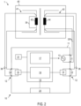
- FIG. 2 is a representation of a system 1 with a device 10 according to a further embodiment.
- the device 10 may, but need not, have a controllable switching means 15 for short-circuiting the high-voltage side 41, wherein the device 10 only falls under the invention if it has such a switching means 15.
- the high-voltage winding 42 must be short-circuited with a line 39 so that the short circuit does not pass through the device 10.
- the device 10 can comprise a reference signal source 21.
- the reference signal source 21 can generate a sinusoidal or other alternating signal with a frequency corresponding to the frequency of the test signal generated by the source 13.
- the evaluation device 18 can determine a phase shift or a time offset between the test response and the test signal by determining the phase position of the test signal relative to the reference signal of the reference signal source 21 and by determining the phase position of the test response relative to the reference signal of the reference signal source 21.
- FIG. 3 and Figure 4 show equivalent circuit diagrams to explain the functioning of the device according to an embodiment.
- FIG. 3 shows an equivalent circuit diagram of the transformer 40.
- the winding resistance R 1 of the high-voltage side 41 can be represented by a resistor 51.
- the transformed winding resistance R 2 ' of the low-voltage side 43 can be represented by a resistor 54.
- the leakage inductance L ⁇ 1 of the high-voltage side 41 can be represented by an inductance 52.
- the transformed leakage inductance L ⁇ 2 ' of the low-voltage side 43 can be represented by an inductance 53.
- the resistors 51, 54 and inductors 52, 53 define the total series inductance of the transformer.
- the inductors 52, 53 define the non-transformed, i.e. unprimed, total stray inductance, which can be converted into a primed characteristic of the transformer by scaling with the square of the transformation ratio in a manner known per se.
- a main inductance carrying the magnetizing current can be taken into account by an inductor 55.
- a linear modeling of losses in the transformer core can be achieved by a resistor 56.
- the device according to one embodiment is designed to impress the test signal on the low-voltage side and, depending on the test response, at least to determine the total longitudinal reactance and/or the total leakage inductance of the transformer 40.
- FIG. 4 shows an equivalent circuit diagram to further explain the functioning of the device 10 according to embodiments.
- the device 10 injects the test signal from source 13 into the low-voltage side of the transformer.
- a voltmeter 65 or other voltage measuring device can detect a voltage V L on the low-voltage side as a first test response.
- a voltmeter 66 or other voltage measuring device can detect a voltage V H on the high-voltage side as a second test response.
- the first and second test responses can be evaluated, for example, as described above, to determine the leakage reactance and/or leakage inductance of the transformer 40.
- the total transformed series impedance is represented by resistor 61 and inductance 62.
- the lines 37 between the device 10 and the transformer 40 have a line impedance to which a line resistance 63 and a line inductance 64 may contribute.
- the total transformed series resistance 61 and the total transformed series reactance which is proportional to the total transformed leakage inductance 62, can be determined.
- the total impedance can be determined from the phase position and amplitude of the voltage V H on the high-voltage side relative to the test signal.
- the line impedance can be determined from the phase position and amplitude of the voltage V H on the high-voltage side relative to the test signal.
- the transformed leakage reactance can be determined as the difference between the imaginary parts of the total impedance and the line impedance. By scaling with the square of the transformation ratio, the leakage reactance can be determined as an unbiased characteristic of the transformer.
- the evaluation and calculation steps for determining the leakage reactance can be carried out automatically by the evaluation device 18.
- a line impedance and/or line reactance of at least one line between the device 10 and the transformer 40 can be determined.
- the source 13 can generate a test signal.
- a test signal generated by source 13 is impressed on the low-voltage side of transformer 40.
- the test signal may be an alternating current signal.
- a test response of the transformer may be acquired.
- the test response may include an AC voltage across a high-voltage winding and another AC voltage across a low-voltage winding, which are acquired as a function of time.
- the leakage reactance and/or the leakage inductance of the transformer 40 are determined.
- the determined leakage reactance and/or the leakage inductance may correspond to the total series reactance or the total leakage inductance of the transformer.
- Method 70 may include further steps. For example, a transmission ratio may be determined automatically. The transmission ratio may be used to convert transformed parameters into untransformed parameters.
- the method 70 may include the evaluation of a user input with which it is possible to user-defined which characteristics of the transformer 40 are determined.
- the method 70 may include controlling a graphical user interface such that the determined leakage reactance and/or leakage inductance is displayed.
- stray reactance and/or stray inductance may be determined by solving a system of matrix equations for elements of a mapping matrix that maps the sine and cosine components of the test signal into corresponding components of one or more test responses.
- the device may comprise a controllable switching means for short-circuiting a winding of the transformer, it may also comprise two or more than two controllable switching means for short-circuiting multiple windings of the transformer, or no such controllable switching means.
- the device may be configured to short-circuit multiple windings simultaneously or sequentially.
- the apparatus and method according to embodiments may also be used when only one characteristic of the transformer, for example only the leakage reactance, is measured before a new user input is required.
- the transformer can be installed in a power plant or substation of a power supply network, the device and the method according to embodiments can also be used for smaller transformers.
- Devices, methods and systems according to embodiments allow determination of parameters such as leakage reactance and/or leakage inductance with further automation in transformer testing.
Landscapes
- Physics & Mathematics (AREA)
- General Physics & Mathematics (AREA)
- Engineering & Computer Science (AREA)
- Power Engineering (AREA)
- Testing Of Short-Circuits, Discontinuities, Leakage, Or Incorrect Line Connections (AREA)
- Measurement Of Resistance Or Impedance (AREA)
Applications Claiming Priority (2)
| Application Number | Priority Date | Filing Date | Title |
|---|---|---|---|
| AT500922015 | 2015-02-06 | ||
| PCT/EP2016/051544 WO2016124443A1 (de) | 2015-02-06 | 2016-01-26 | Vorrichtung und verfahren zum ermitteln einer kenngrösse eines transformators |
Publications (3)
| Publication Number | Publication Date |
|---|---|
| EP3254124A1 EP3254124A1 (de) | 2017-12-13 |
| EP3254124B1 true EP3254124B1 (de) | 2025-04-30 |
| EP3254124C0 EP3254124C0 (de) | 2025-04-30 |
Family
ID=55229711
Family Applications (1)
| Application Number | Title | Priority Date | Filing Date |
|---|---|---|---|
| EP16701515.5A Active EP3254124B1 (de) | 2015-02-06 | 2016-01-26 | Vorrichtung und verfahren zum ermitteln einer kenngrösse eines transformators |
Country Status (13)
| Country | Link |
|---|---|
| US (1) | US10794964B2 (pl) |
| EP (1) | EP3254124B1 (pl) |
| KR (1) | KR101952215B1 (pl) |
| CN (1) | CN107407706B (pl) |
| AU (1) | AU2016214660B2 (pl) |
| BR (1) | BR112017015960B1 (pl) |
| CA (1) | CA2975007C (pl) |
| ES (1) | ES3033848T3 (pl) |
| MX (1) | MX383796B (pl) |
| PL (1) | PL3254124T3 (pl) |
| RU (1) | RU2675197C1 (pl) |
| WO (1) | WO2016124443A1 (pl) |
| ZA (1) | ZA201705198B (pl) |
Families Citing this family (9)
| Publication number | Priority date | Publication date | Assignee | Title |
|---|---|---|---|---|
| ES3033848T3 (en) | 2015-02-06 | 2025-08-08 | Omicron Electronics Gmbh | Device and method for determining a parameter of a transformer |
| DE102016220030A1 (de) * | 2016-10-14 | 2018-04-19 | Robert Bosch Gmbh | Verfahren zum Erkennen eines Kurzschlusses über eine Last |
| CN108919035B (zh) * | 2018-08-23 | 2021-06-01 | 重庆深长蓝嘉电力工程有限公司 | 一种变压器用调压功能通电及漏电检测装置 |
| CN109470132A (zh) * | 2018-10-31 | 2019-03-15 | 广州供电局有限公司 | 变压器绕组形变检测方法、装置及设备 |
| DE102019105861A1 (de) | 2019-03-07 | 2020-09-10 | Sma Solar Technology Ag | Verfahren und Vorrichtung zur näherungsweisen Bestimmung von Spannungen an einer Oberspannungsseite eines Transformators |
| CN112964948B (zh) * | 2021-02-05 | 2022-07-12 | 国网浙江省电力有限公司检修分公司 | 基于录波数据反演的串联电抗器运行状态在线监测方法及系统 |
| AT525068B1 (de) * | 2021-08-20 | 2022-12-15 | Omicron Electronics Gmbh | Verfahren und Vorrichtung zum Prüfen eines Spannungswandlers |
| KR102810195B1 (ko) | 2022-01-03 | 2025-05-21 | 고려대학교 산학협력단 | 기계학습을 이용한 변압기 주파수 응답 모델 파라미터의 추정 장치 및 방법 |
| CN117783954B (zh) * | 2023-12-28 | 2024-08-06 | 西南交通大学 | 一种基于阶跃响应动态波段选择的变压器故障诊断方法 |
Citations (1)
| Publication number | Priority date | Publication date | Assignee | Title |
|---|---|---|---|---|
| WO2016066701A1 (de) * | 2014-10-30 | 2016-05-06 | Omicron Electronics Gmbh | Transformatorprüfvorrichtung und verfahren zum prüfen eines transformators |
Family Cites Families (14)
| Publication number | Priority date | Publication date | Assignee | Title |
|---|---|---|---|---|
| US3938030A (en) * | 1974-07-18 | 1976-02-10 | Cornwell Lionel B | Controllable power transferring device utilizing a short-circuited controlled reactance |
| JPH10201226A (ja) | 1996-12-30 | 1998-07-31 | Murata Mfg Co Ltd | 高電圧発生回路 |
| TWI254135B (en) * | 2004-11-26 | 2006-05-01 | Chroma Ate Inc | Process and device of high voltage test with detecting function for short/open circuit |
| WO2009018850A1 (de) | 2007-08-06 | 2009-02-12 | Siemens Aktiengesellschaft | Verfahren zur ermittlung der magnetischen streuflusskopplung eines transformators |
| DE102009023505A1 (de) | 2009-06-02 | 2010-12-09 | Austriamicrosystems Ag | Schaltungsanordnung für einen Piezotransformator und dazugehörendes Verfahren |
| EP2466322B1 (en) * | 2010-12-17 | 2013-09-11 | ABB Research Ltd. | Method and apparatus for transformer diagnosis |
| CN102291025A (zh) | 2011-08-19 | 2011-12-21 | 深圳市英威腾电气股份有限公司 | 逆变器系统的控制方法、装置及逆变器系统 |
| CN102721898A (zh) | 2012-02-27 | 2012-10-10 | 衢州电力局 | 变压器绕组变形在线测量方法及系统 |
| CN102749515A (zh) | 2012-06-21 | 2012-10-24 | 魏明 | 变压器绕组漏抗测量方法 |
| WO2014071293A1 (en) | 2012-11-05 | 2014-05-08 | Doble Engineering Company | Method and apparatus for testing utility power devices |
| CN102967763B (zh) | 2012-11-30 | 2014-11-05 | 南京南瑞继保电气有限公司 | 一种变压器短路阻抗计算方法 |
| CN103063988B (zh) | 2012-12-28 | 2014-12-31 | 成都泰格微电子研究所有限责任公司 | 表面贴装无源微波电路的功率承受能力测试方法 |
| ES2749449T3 (es) | 2013-04-05 | 2020-03-20 | Omicron Electronics Gmbh | Método y dispositivo para el ensayo de un transformador |
| ES3033848T3 (en) | 2015-02-06 | 2025-08-08 | Omicron Electronics Gmbh | Device and method for determining a parameter of a transformer |
-
2016
- 2016-01-26 ES ES16701515T patent/ES3033848T3/es active Active
- 2016-01-26 MX MX2017010005A patent/MX383796B/es unknown
- 2016-01-26 WO PCT/EP2016/051544 patent/WO2016124443A1/de not_active Ceased
- 2016-01-26 RU RU2017130278A patent/RU2675197C1/ru active
- 2016-01-26 US US15/548,950 patent/US10794964B2/en active Active
- 2016-01-26 EP EP16701515.5A patent/EP3254124B1/de active Active
- 2016-01-26 AU AU2016214660A patent/AU2016214660B2/en active Active
- 2016-01-26 BR BR112017015960-0A patent/BR112017015960B1/pt active IP Right Grant
- 2016-01-26 CN CN201680008570.2A patent/CN107407706B/zh active Active
- 2016-01-26 CA CA2975007A patent/CA2975007C/en active Active
- 2016-01-26 KR KR1020177022201A patent/KR101952215B1/ko active Active
- 2016-01-26 PL PL16701515.5T patent/PL3254124T3/pl unknown
-
2017
- 2017-08-01 ZA ZA2017/05198A patent/ZA201705198B/en unknown
Patent Citations (2)
| Publication number | Priority date | Publication date | Assignee | Title |
|---|---|---|---|---|
| WO2016066701A1 (de) * | 2014-10-30 | 2016-05-06 | Omicron Electronics Gmbh | Transformatorprüfvorrichtung und verfahren zum prüfen eines transformators |
| EP3213095A1 (de) * | 2014-10-30 | 2017-09-06 | Omicron electronics GmbH | Transformatorprüfvorrichtung und verfahren zum prüfen eines transformators |
Also Published As
| Publication number | Publication date |
|---|---|
| US10794964B2 (en) | 2020-10-06 |
| AU2016214660B2 (en) | 2019-08-22 |
| CA2975007C (en) | 2021-11-23 |
| WO2016124443A1 (de) | 2016-08-11 |
| US20180024180A1 (en) | 2018-01-25 |
| KR101952215B1 (ko) | 2019-02-26 |
| CN107407706A (zh) | 2017-11-28 |
| ZA201705198B (en) | 2019-06-26 |
| RU2675197C1 (ru) | 2018-12-17 |
| ES3033848T3 (en) | 2025-08-08 |
| MX383796B (es) | 2025-03-14 |
| BR112017015960A2 (pt) | 2018-03-20 |
| PL3254124T3 (pl) | 2025-08-18 |
| CN107407706B (zh) | 2019-11-08 |
| MX2017010005A (es) | 2017-11-22 |
| KR20170113572A (ko) | 2017-10-12 |
| EP3254124C0 (de) | 2025-04-30 |
| AU2016214660A1 (en) | 2017-08-10 |
| CA2975007A1 (en) | 2016-08-11 |
| EP3254124A1 (de) | 2017-12-13 |
| BR112017015960B1 (pt) | 2024-04-30 |
Similar Documents
| Publication | Publication Date | Title |
|---|---|---|
| EP3254124B1 (de) | Vorrichtung und verfahren zum ermitteln einer kenngrösse eines transformators | |
| EP3213095B1 (de) | Transformatorprüfvorrichtung und verfahren zum prüfen eines transformators | |
| EP3245527B1 (de) | Transformatorprüfvorrichtung und verfahren zum prüfen eines transformators | |
| EP1398644B1 (de) | Verfahren zum Testen eines Transformators und entsprechende Testvorrichtung | |
| AT517620B1 (de) | Verfahren und Prüfvorrichtung zum Prüfen einer Verdrahtung von Wandlern | |
| EP3391063B1 (de) | Mobile transformatorprüfvorrichtung und verfahren zum prüfen eines leistungstransformators | |
| DE102009060200A1 (de) | Vorrichtung zum Erkennen einer verschlechterten Motorisolation | |
| EP3254127B1 (de) | Transformatorprüfvorrichtung und verfahren zum prüfen eines dreiwicklungstransformators | |
| EP3599472B1 (de) | Verfahren und vorrichtung zum erfassen von isolationsparametern | |
| DE102013107968A1 (de) | Online-Überwachungssystem für den Einsatz in elektrischen Anlagen und Verfahren zu dessen Betrieb | |
| EP3308179B1 (de) | Schaltvorrichtung, testvorrichtung und verfahren zum betreiben einer schaltvorrichtung für ein messgerät für einen transformator | |
| EP2869072A1 (de) | Einrichtung und Verfahren zur Erfassung der elektrischen Energie von ein- oder mehrphasigen Verbrauchern | |
| DE69217996T2 (de) | Gerät zum Prüfen von Wicklungskomponenten | |
| DE10207856A1 (de) | Verfahren und Vorrichtung zur Messung der Impedanz eines elektrischen Energieversorgungsnetzes | |
| EP3230990B1 (de) | Entmagnetisierungsvorrichtung und verfahren zum entmagnetisieren eines wandlerkerns | |
| DE102012210897A1 (de) | Objekterkennung für ein Energieübertragungssystem | |
| DE102019218803A1 (de) | Verfahren zum Bestimmen der Alterung eines Hochspannungsgeräts | |
| DE102018106940A1 (de) | Messvorrichtung, Messsystem und Verfahren zur verteilten Energiemessung | |
| DE102021119207A1 (de) | Vorrichtung und Verfahren zur Identifikation einer Zuordnung von einem Phasenanschluss eines elektrischen Gerätes zu einem damit verbundenen Phasenleiter | |
| EP3252482A1 (de) | Verfahren und leitstelleneinrichtung zum bestimmen eines phasenwinkels einer leistungspendelung in einem elektrischen energieversorgungsnetz | |
| BE1026134B1 (de) | Messvorrichtung, Messsystem und Verfahren zur verteilten Energiemessung | |
| LU101628B1 (de) | Strommessumformer zum Messen des durch einen elektrischen Leiter fließenden Stroms und Verfahren zur Ausgabe der Stromstärke bei einem Strommessumformer mit Ausgabe der Energieflussrichtung bei Wechselströmen | |
| DE619518C (de) | Einrichtung zur Ermittlung des Kompensationsgrades von Hochspannungsanlagen | |
| DE102024109452A1 (de) | Einheitliches messsystem zur statischen und dynamischen charakterisierung einer zu testenden vorrichtung | |
| WO2016166050A1 (de) | Transformator, prüfvorrichtung und verfahren zum prüfen eines prüflings einer energietechnischen anlage |
Legal Events
| Date | Code | Title | Description |
|---|---|---|---|
| STAA | Information on the status of an ep patent application or granted ep patent |
Free format text: STATUS: THE INTERNATIONAL PUBLICATION HAS BEEN MADE |
|
| PUAI | Public reference made under article 153(3) epc to a published international application that has entered the european phase |
Free format text: ORIGINAL CODE: 0009012 |
|
| STAA | Information on the status of an ep patent application or granted ep patent |
Free format text: STATUS: REQUEST FOR EXAMINATION WAS MADE |
|
| 17P | Request for examination filed |
Effective date: 20170904 |
|
| AK | Designated contracting states |
Kind code of ref document: A1 Designated state(s): AL AT BE BG CH CY CZ DE DK EE ES FI FR GB GR HR HU IE IS IT LI LT LU LV MC MK MT NL NO PL PT RO RS SE SI SK SM TR |
|
| AX | Request for extension of the european patent |
Extension state: BA ME |
|
| RIN1 | Information on inventor provided before grant (corrected) |
Inventor name: SAPETSCHNIG, RENE Inventor name: PUETTER, MARKUS |
|
| DAV | Request for validation of the european patent (deleted) | ||
| DAX | Request for extension of the european patent (deleted) | ||
| STAA | Information on the status of an ep patent application or granted ep patent |
Free format text: STATUS: EXAMINATION IS IN PROGRESS |
|
| 17Q | First examination report despatched |
Effective date: 20210628 |
|
| P01 | Opt-out of the competence of the unified patent court (upc) registered |
Effective date: 20230324 |
|
| REG | Reference to a national code |
Ref country code: DE Free format text: PREVIOUS MAIN CLASS: G01R0027260000 Ref country code: DE Ref legal event code: R079 Ref document number: 502016016966 Country of ref document: DE Free format text: PREVIOUS MAIN CLASS: G01R0027260000 Ipc: G01R0031620000 |
|
| GRAP | Despatch of communication of intention to grant a patent |
Free format text: ORIGINAL CODE: EPIDOSNIGR1 |
|
| STAA | Information on the status of an ep patent application or granted ep patent |
Free format text: STATUS: GRANT OF PATENT IS INTENDED |
|
| RIC1 | Information provided on ipc code assigned before grant |
Ipc: G01R 27/26 20060101ALI20241206BHEP Ipc: G01R 31/62 20200101AFI20241206BHEP |
|
| INTG | Intention to grant announced |
Effective date: 20241219 |
|
| GRAS | Grant fee paid |
Free format text: ORIGINAL CODE: EPIDOSNIGR3 |
|
| GRAA | (expected) grant |
Free format text: ORIGINAL CODE: 0009210 |
|
| STAA | Information on the status of an ep patent application or granted ep patent |
Free format text: STATUS: THE PATENT HAS BEEN GRANTED |
|
| AK | Designated contracting states |
Kind code of ref document: B1 Designated state(s): AL AT BE BG CH CY CZ DE DK EE ES FI FR GB GR HR HU IE IS IT LI LT LU LV MC MK MT NL NO PL PT RO RS SE SI SK SM TR |
|
| REG | Reference to a national code |
Ref country code: CH Ref legal event code: EP Ref country code: GB Ref legal event code: FG4D Free format text: NOT ENGLISH |
|
| REG | Reference to a national code |
Ref country code: DE Ref legal event code: R096 Ref document number: 502016016966 Country of ref document: DE |
|
| REG | Reference to a national code |
Ref country code: IE Ref legal event code: FG4D Free format text: LANGUAGE OF EP DOCUMENT: GERMAN |
|
| U01 | Request for unitary effect filed |
Effective date: 20250528 |
|
| P04 | Withdrawal of opt-out of the competence of the unified patent court (upc) registered |
Free format text: CASE NUMBER: APP_26165/2025 Effective date: 20250602 |
|
| U07 | Unitary effect registered |
Designated state(s): AT BE BG DE DK EE FI FR IT LT LU LV MT NL PT RO SE SI Effective date: 20250605 |
|
| REG | Reference to a national code |
Ref country code: ES Ref legal event code: FG2A Ref document number: 3033848 Country of ref document: ES Kind code of ref document: T3 Effective date: 20250808 |
|
| PG25 | Lapsed in a contracting state [announced via postgrant information from national office to epo] |
Ref country code: NO Free format text: LAPSE BECAUSE OF FAILURE TO SUBMIT A TRANSLATION OF THE DESCRIPTION OR TO PAY THE FEE WITHIN THE PRESCRIBED TIME-LIMIT Effective date: 20250730 Ref country code: GR Free format text: LAPSE BECAUSE OF FAILURE TO SUBMIT A TRANSLATION OF THE DESCRIPTION OR TO PAY THE FEE WITHIN THE PRESCRIBED TIME-LIMIT Effective date: 20250731 |
|
| PG25 | Lapsed in a contracting state [announced via postgrant information from national office to epo] |
Ref country code: HR Free format text: LAPSE BECAUSE OF FAILURE TO SUBMIT A TRANSLATION OF THE DESCRIPTION OR TO PAY THE FEE WITHIN THE PRESCRIBED TIME-LIMIT Effective date: 20250430 |
|
| PG25 | Lapsed in a contracting state [announced via postgrant information from national office to epo] |
Ref country code: RS Free format text: LAPSE BECAUSE OF FAILURE TO SUBMIT A TRANSLATION OF THE DESCRIPTION OR TO PAY THE FEE WITHIN THE PRESCRIBED TIME-LIMIT Effective date: 20250731 |
|
| PG25 | Lapsed in a contracting state [announced via postgrant information from national office to epo] |
Ref country code: IS Free format text: LAPSE BECAUSE OF FAILURE TO SUBMIT A TRANSLATION OF THE DESCRIPTION OR TO PAY THE FEE WITHIN THE PRESCRIBED TIME-LIMIT Effective date: 20250830 |