EP3253552B1 - Procédé de contrôle-commande d'une machine d'extrusion bi-vis, ainsi que machine d'extrusion bi-vis - Google Patents
Procédé de contrôle-commande d'une machine d'extrusion bi-vis, ainsi que machine d'extrusion bi-vis Download PDFInfo
- Publication number
- EP3253552B1 EP3253552B1 EP16703468.5A EP16703468A EP3253552B1 EP 3253552 B1 EP3253552 B1 EP 3253552B1 EP 16703468 A EP16703468 A EP 16703468A EP 3253552 B1 EP3253552 B1 EP 3253552B1
- Authority
- EP
- European Patent Office
- Prior art keywords
- extruder
- sheath
- flow channel
- viscosity
- screws
- Prior art date
- Legal status (The legal status is an assumption and is not a legal conclusion. Google has not performed a legal analysis and makes no representation as to the accuracy of the status listed.)
- Active
Links
Images


Classifications
-
- B—PERFORMING OPERATIONS; TRANSPORTING
- B29—WORKING OF PLASTICS; WORKING OF SUBSTANCES IN A PLASTIC STATE IN GENERAL
- B29C—SHAPING OR JOINING OF PLASTICS; SHAPING OF MATERIAL IN A PLASTIC STATE, NOT OTHERWISE PROVIDED FOR; AFTER-TREATMENT OF THE SHAPED PRODUCTS, e.g. REPAIRING
- B29C48/00—Extrusion moulding, i.e. expressing the moulding material through a die or nozzle which imparts the desired form; Apparatus therefor
- B29C48/25—Component parts, details or accessories; Auxiliary operations
- B29C48/92—Measuring, controlling or regulating
-
- B—PERFORMING OPERATIONS; TRANSPORTING
- B29—WORKING OF PLASTICS; WORKING OF SUBSTANCES IN A PLASTIC STATE IN GENERAL
- B29C—SHAPING OR JOINING OF PLASTICS; SHAPING OF MATERIAL IN A PLASTIC STATE, NOT OTHERWISE PROVIDED FOR; AFTER-TREATMENT OF THE SHAPED PRODUCTS, e.g. REPAIRING
- B29C48/00—Extrusion moulding, i.e. expressing the moulding material through a die or nozzle which imparts the desired form; Apparatus therefor
- B29C48/25—Component parts, details or accessories; Auxiliary operations
- B29C48/255—Flow control means, e.g. valves
- B29C48/2556—Flow control means, e.g. valves provided in or in the proximity of dies
-
- B—PERFORMING OPERATIONS; TRANSPORTING
- B29—WORKING OF PLASTICS; WORKING OF SUBSTANCES IN A PLASTIC STATE IN GENERAL
- B29C—SHAPING OR JOINING OF PLASTICS; SHAPING OF MATERIAL IN A PLASTIC STATE, NOT OTHERWISE PROVIDED FOR; AFTER-TREATMENT OF THE SHAPED PRODUCTS, e.g. REPAIRING
- B29C48/00—Extrusion moulding, i.e. expressing the moulding material through a die or nozzle which imparts the desired form; Apparatus therefor
- B29C48/25—Component parts, details or accessories; Auxiliary operations
- B29C48/36—Means for plasticising or homogenising the moulding material or forcing it through the nozzle or die
- B29C48/395—Means for plasticising or homogenising the moulding material or forcing it through the nozzle or die using screws surrounded by a cooperating barrel, e.g. single screw extruders
- B29C48/40—Means for plasticising or homogenising the moulding material or forcing it through the nozzle or die using screws surrounded by a cooperating barrel, e.g. single screw extruders using two or more parallel screws or at least two parallel non-intermeshing screws, e.g. twin screw extruders
- B29C48/402—Means for plasticising or homogenising the moulding material or forcing it through the nozzle or die using screws surrounded by a cooperating barrel, e.g. single screw extruders using two or more parallel screws or at least two parallel non-intermeshing screws, e.g. twin screw extruders the screws having intermeshing parts
-
- B—PERFORMING OPERATIONS; TRANSPORTING
- B29—WORKING OF PLASTICS; WORKING OF SUBSTANCES IN A PLASTIC STATE IN GENERAL
- B29C—SHAPING OR JOINING OF PLASTICS; SHAPING OF MATERIAL IN A PLASTIC STATE, NOT OTHERWISE PROVIDED FOR; AFTER-TREATMENT OF THE SHAPED PRODUCTS, e.g. REPAIRING
- B29C2948/00—Indexing scheme relating to extrusion moulding
- B29C2948/92—Measuring, controlling or regulating
- B29C2948/92009—Measured parameter
- B29C2948/922—Viscosity; Melt flow index [MFI]; Molecular weight
-
- B—PERFORMING OPERATIONS; TRANSPORTING
- B29—WORKING OF PLASTICS; WORKING OF SUBSTANCES IN A PLASTIC STATE IN GENERAL
- B29C—SHAPING OR JOINING OF PLASTICS; SHAPING OF MATERIAL IN A PLASTIC STATE, NOT OTHERWISE PROVIDED FOR; AFTER-TREATMENT OF THE SHAPED PRODUCTS, e.g. REPAIRING
- B29C2948/00—Indexing scheme relating to extrusion moulding
- B29C2948/92—Measuring, controlling or regulating
- B29C2948/92323—Location or phase of measurement
- B29C2948/92361—Extrusion unit
- B29C2948/9238—Feeding, melting, plasticising or pumping zones, e.g. the melt itself
- B29C2948/924—Barrel or housing
-
- B—PERFORMING OPERATIONS; TRANSPORTING
- B29—WORKING OF PLASTICS; WORKING OF SUBSTANCES IN A PLASTIC STATE IN GENERAL
- B29C—SHAPING OR JOINING OF PLASTICS; SHAPING OF MATERIAL IN A PLASTIC STATE, NOT OTHERWISE PROVIDED FOR; AFTER-TREATMENT OF THE SHAPED PRODUCTS, e.g. REPAIRING
- B29C2948/00—Indexing scheme relating to extrusion moulding
- B29C2948/92—Measuring, controlling or regulating
- B29C2948/92323—Location or phase of measurement
- B29C2948/92361—Extrusion unit
- B29C2948/92409—Die; Nozzle zone
-
- B—PERFORMING OPERATIONS; TRANSPORTING
- B29—WORKING OF PLASTICS; WORKING OF SUBSTANCES IN A PLASTIC STATE IN GENERAL
- B29C—SHAPING OR JOINING OF PLASTICS; SHAPING OF MATERIAL IN A PLASTIC STATE, NOT OTHERWISE PROVIDED FOR; AFTER-TREATMENT OF THE SHAPED PRODUCTS, e.g. REPAIRING
- B29C2948/00—Indexing scheme relating to extrusion moulding
- B29C2948/92—Measuring, controlling or regulating
- B29C2948/92504—Controlled parameter
- B29C2948/9258—Velocity
- B29C2948/9259—Angular velocity
-
- B—PERFORMING OPERATIONS; TRANSPORTING
- B29—WORKING OF PLASTICS; WORKING OF SUBSTANCES IN A PLASTIC STATE IN GENERAL
- B29C—SHAPING OR JOINING OF PLASTICS; SHAPING OF MATERIAL IN A PLASTIC STATE, NOT OTHERWISE PROVIDED FOR; AFTER-TREATMENT OF THE SHAPED PRODUCTS, e.g. REPAIRING
- B29C2948/00—Indexing scheme relating to extrusion moulding
- B29C2948/92—Measuring, controlling or regulating
- B29C2948/92504—Controlled parameter
- B29C2948/9258—Velocity
- B29C2948/926—Flow or feed rate
-
- B—PERFORMING OPERATIONS; TRANSPORTING
- B29—WORKING OF PLASTICS; WORKING OF SUBSTANCES IN A PLASTIC STATE IN GENERAL
- B29C—SHAPING OR JOINING OF PLASTICS; SHAPING OF MATERIAL IN A PLASTIC STATE, NOT OTHERWISE PROVIDED FOR; AFTER-TREATMENT OF THE SHAPED PRODUCTS, e.g. REPAIRING
- B29C2948/00—Indexing scheme relating to extrusion moulding
- B29C2948/92—Measuring, controlling or regulating
- B29C2948/92504—Controlled parameter
- B29C2948/92695—Viscosity; Melt flow index [MFI]; Molecular weight
-
- B—PERFORMING OPERATIONS; TRANSPORTING
- B29—WORKING OF PLASTICS; WORKING OF SUBSTANCES IN A PLASTIC STATE IN GENERAL
- B29C—SHAPING OR JOINING OF PLASTICS; SHAPING OF MATERIAL IN A PLASTIC STATE, NOT OTHERWISE PROVIDED FOR; AFTER-TREATMENT OF THE SHAPED PRODUCTS, e.g. REPAIRING
- B29C2948/00—Indexing scheme relating to extrusion moulding
- B29C2948/92—Measuring, controlling or regulating
- B29C2948/92504—Controlled parameter
- B29C2948/92704—Temperature
-
- B—PERFORMING OPERATIONS; TRANSPORTING
- B29—WORKING OF PLASTICS; WORKING OF SUBSTANCES IN A PLASTIC STATE IN GENERAL
- B29C—SHAPING OR JOINING OF PLASTICS; SHAPING OF MATERIAL IN A PLASTIC STATE, NOT OTHERWISE PROVIDED FOR; AFTER-TREATMENT OF THE SHAPED PRODUCTS, e.g. REPAIRING
- B29C2948/00—Indexing scheme relating to extrusion moulding
- B29C2948/92—Measuring, controlling or regulating
- B29C2948/92504—Controlled parameter
- B29C2948/92723—Content, e.g. percentage of humidity, volatiles, contaminants or degassing
-
- B—PERFORMING OPERATIONS; TRANSPORTING
- B29—WORKING OF PLASTICS; WORKING OF SUBSTANCES IN A PLASTIC STATE IN GENERAL
- B29C—SHAPING OR JOINING OF PLASTICS; SHAPING OF MATERIAL IN A PLASTIC STATE, NOT OTHERWISE PROVIDED FOR; AFTER-TREATMENT OF THE SHAPED PRODUCTS, e.g. REPAIRING
- B29C2948/00—Indexing scheme relating to extrusion moulding
- B29C2948/92—Measuring, controlling or regulating
- B29C2948/92819—Location or phase of control
- B29C2948/92857—Extrusion unit
Definitions
- the present invention relates to a twin-screw extrusion machine, as well as a control-command method of such a machine.
- the invention is concerned with twin-screw extrusion machines, which comprise a sheath, generally thermoregulated, inside which two interpenetrating screws are rotated on themselves so that they cause a material to extruding from an upstream portion of the sleeve to the downstream end of the sleeve where the material is then forced to flow through an output device which often includes a die for shaping the extruded material.
- twin-screw extrusion machines which comprise a sheath, generally thermoregulated, inside which two interpenetrating screws are rotated on themselves so that they cause a material to extruding from an upstream portion of the sleeve to the downstream end of the sleeve where the material is then forced to flow through an output device which often includes a die for shaping the extruded material.
- the material undergoes both a mechanical transformation, by pressurization and shearing by the screws, and a thermal transformation, by regulating the temperature along the sheath.
- thermomechanical adjustment parameters of the extrusion machine which are, inter alia, the speed of rotation. screws, the geometry of the screws, the temperature imposed on the sheath and the feed rate of the raw material in the extrusion machine, but also the quality of the raw material introduced into the extrusion machine: indeed, the quality of each of the ingredients of this raw material may vary, in particular because of their physicochemical variability (moisture content, fat content, granulometry, etc.), their origin or their storage conditions, so that the quality of the extruded material is affected at constant adjustment of the extrusion machine.
- SME mechanical specific energy quantity
- the SME corresponds to the energy supplied by the screw driving motor of the extrusion machine, relative to the mass unit of extruded material.
- the SME reflects the level of the mechanical transformation of the material being extruded.
- the prior art teaches that by constantly measuring the EMS, the extrusion machine can be regulated by adjusting, at the level of the running part of the screws, a passage section for the material being extruded: the idea is to "buckle”, in other words to enslave a variation of passage section for the material being extruded, with the measurement of the EMS.
- US 2004/0020272 proposes during the extrusion of a polymer by a twin-screw extrusion machine, rheological measurements of the material treated by the extrusion machine, these measurements being in line, that is to say in the flow of the material inside the extrusion machine.
- pressure and temperature sensors are arranged on the extrusion machine, more precisely at an output die of this machine, and at the space between the downstream end of the screws. and the industry.
- the different measurements are used to calculate, among other things, the viscosity of the material in the extrusion machine. More generally, these measurements are processed in real time to control the quality of the extruded polymer, as well as to regulate the extrusion machine, without however US 2004/0020272 does not explain how to implement this regulation.
- the object of the present invention is to propose a more effective and complete response to the control-command problem of extrusion machines in order to obtain a final extruded material of controlled quality.
- the subject of the invention is a control-command method of an extrusion machine as defined in claim 1.
- One of the ideas underlying the invention is to use the measurement of the viscosity of the material in the extrusion machine, the viscosity being a relevant marker of the rheological variations of the material being extruded.
- This measurement is provided in line, that is to say in the flow of the material inside the extrusion machine: indeed, to ensure a real-time regulation, the evolution of the viscosity must be appreciated constantly for the material being extruded.
- the viscosity is the result of effects of shear, pressure, residence time, temperature, etc. applied to the extruded material.
- the viscosity corresponds to the resistance to the flow of a material under the influence of at least one stress such as shear, pressure, gravity, etc.
- the invention thus proposes to continuously measure the viscosity of the material being extruded and to adjust in real time, from this continuous measurement, a passage section for the material at the outlet of the extrusion machine. that is to say for the material in this machine downstream of its screws: by playing on this section of passage of the extrusion machine while all things are equal elsewhere, correspondingly modifies the rate of filling of the machine by the material being extruded, more precisely its filling rate along its interpenetrating screws which advance the material within the machine, which correspondingly varies the viscosity of the material in progress extrusion.
- one or more actuators of the extrusion machine line other than the section changeover actuator for the material in the downstream extrusion machine. screws of the latter, can be implemented in combination with the actuation of the adjustment of this passage section, always from the in-line measurement of the viscosity. The control-command performance of the extrusion machine is improved.
- the nature of the extruded material is indifferent: the invention relates both to the extrusion of food and non-food materials, such as plastics, chemicals, pharmaceuticals, etc.
- non-food materials such as plastics, chemicals, pharmaceuticals, etc.
- the process according to the invention finds a particularly advantageous application when the material to be extruded is non-Newtonian, in particular food, as referred to in claim 5.
- a fluid is considered here as non-Newtonian since its viscosity depends on shear rate.
- the invention makes it possible to effectively regulate the twin-screw extrusion machine by varying its filling rate, so that , all along the screws, the material is sheared or, more generally, constrained, thus impacting the viscosity on the whole of the material, except for marginal portions and therefore negligible thereof.
- the invention also relates to an extrusion machine as defined in claim 6.
- extrusion machine 1 commonly called “twin-screw extruder”.
- This extrusion machine 1 comprises a sleeve 10 of elongate shape, which extends along and which is centered on geometric axis XX. Inside the sleeve 10, two screws 20 extend parallel to the axis XX, being received in a complementary longitudinal bore of the sleeve, centered on the axis XX. These two screws 20 extend on either side of the axis XX, while being interpenetrating, the aforementioned bore of the sheath 10 having a bilobed transverse profile. Each screw 20 is rotated on itself, about its central axis, by a driving unit, not shown on the figure 1 , in mechanical engagement with an upstream end of the screw, namely that of the right on the figure 1 , emerging outside the sheath 10.
- the screws 20 of the extrusion machine 1 are designed, by their threaded profile, to cause a material to be extruded along the axis XX, from an upstream part of the sleeve 10, in which the ingredient or ingredients of this material are introduced into the aforementioned bore of the sleeve, to the downstream end of the sleeve 10, the terms "upstream” and “downstream” being oriented in the direction of progression of the material inside the sleeve under the action of screw 20, this direction of progression being from right to left on the figures 1 and 2 .
- the screws 20 are designed to, in addition to driving the material to extrude, shear and pressurize this material, so as to transform it mechanically .
- This aspect of the extrusion machine 1 being well known in the art, it will not be described here further.
- the sheath 10 comprises several modular elements succeeding each other along the axis XX, which are here five in number, being respectively referenced 11 to 15 of upstream to downstream.
- Each of the elements 11 to 15 delimits internally a corresponding portion of the central longitudinal bore of the sheath 10, these boring portions being in the extension of each other, along the axis XX, in the assembled state of the elements 11 to 15, as on the figure 1 .
- the elements 11 to 15 are assembled in pairs by fastening collars 16.
- the element 11 upstream allows to introduce, within its central bore portion, one or more at least partially solid ingredients of the material to be extruded.
- this element 11 is provided with a through hole 11A, which, transversely to the axis XX, opens on the outside the central bore portion of this element 11 and in which opens a feed hopper 31 at least the aforementioned at least partially solid ingredients.
- the element 12 is designed to introduce, from the outside, one or more liquid ingredients within the corresponding central bore portion.
- the element 12 is provided with one or more through orifices which, transversely to the axis XX, connect the aforementioned bore portion to one or more pumps 32 of injection of this or these liquid ingredients. More generally, it is understood that among the elements 11 to 15 of the sheath 10, one or more of them allow to introduce, within the central longitudinal bore of the sheath 10, the ingredient or ingredients of the material to extrude by the extrusion machine 1.
- the plate 41 is fixedly attached, for example by a clamping collar 50, to the downstream end of the element 15, the downstream end of the sleeve 10.
- this plate 41 internally delimits a through bore, which is centered on the axis XX, which extends in the extension, along this axis, of the central bore portion of the element 15, and within which is received the free downstream end each screw 20.
- the central bore of the plate 41 channels the material exiting the sleeve 10 pushed downstream by the screws 20.
- the central bore of the plate 41 is advantageously converge downstream, in particular to maximize the filling of the downstream end of this bore with the material coming out of the sheath 10.
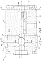
- the module 43 which will be described in more detail below, comprises a main housing 43.1, which is interposed, in the direction of the axis XX, between the downstream end of the plate 41 and the upstream end of the die. 42, being attached thereto by respective collars 44 and 45, and which internally delimits a material flow channel 43A from the downstream end of the plate 41 to the upstream end of the die 42.
- This flow channel 43A passes through the housing 43.1 axially from one side, connecting the opposite axial ends thereof, being substantially centered on the axis XX and thus extending in the axial extension of the bore central plate 41 and the central longitudinal bore of the sleeve 10, as clearly visible on the figure 1 .
- the die 42 is designed to shape the extruded material by the extrusion machine 1, this material being forced, under the action of the screws 20, to pass through outlets 42.1 to the downstream, delimited internally by the die 42.
- the embodiment of the die 42 is not limiting of the invention: in particular, the number, the arrangement and, more generally, the characteristics of the outlet orifices 42.1 are indifferent .
- the die 42 is equipped, at its upstream end, with a diffuser 42.2 which distributes the material entering the die between its outlet orifices 42.1, the internal volume, diverging downstream, of this diffuser 42.2 being, upstream, connected to the downstream end of the flow channel 43A of the module 43 and, downstream, connected to the upstream end of the outlet orifices 42.1 .
- the latter comprises a viscosity measuring sensor 43.2 which, at least in part, is arranged in the flow channel 43A so as to continuously measure the viscosity of the material flowing in it.
- channel 43A in other words to measure in-line the viscosity of the material inside the extrusion machine 1.
- the sensor 43.2 can therefore be called integrated sensor.
- This sensor 43.2 is, in itself, a known technology and is commercially available.
- This sensor 43.2 is designed to produce, permanently and in real time, a signal, indicated schematically by the arrow S1 on the figure 1 , representative of the viscosity of the material flowing in the channel 43A from the interaction between this flow material and the part of the sensor 43.2 arranged in the channel 43A and therefore in contact with this material.
- the aforementioned signal S1 is transmitted to the outside of the module 43 by any appropriate means, for example by a wired connection in the case where this signal is electrical in nature.
- the integration of the sensor 43.2 and its installation in the flow channel 43A meet the requirements of hygiene, flow and measurement of the material to be extruded.
- the sensor 43.2 is fixedly supported by a base 43.3, which is attached, in a fixed and sealed manner, in a dedicated complementary housing 43B delimited by the casing 43.1 transversely to the X-X axis.
- the aforementioned wired link is, in a manner not shown in the figures, provided to join the outside of the module 43 via this base 43.3.
- the module 43 also comprises a variable shutter 43.4 flap of the flow channel 43A, which is arranged across this channel 43A pivotally about a geometric axis ZZ perpendicular to the axis XX and therefore perpendicular to the direction flow of the material in the channel 43A.
- the flap 43.4 makes it possible to vary the passage section of the flow channel 43A, in other words the passage section for the material being extruded in the extrusion machine 1.
- the flap 43.4 occupies a pivoted position intermediate between, on the one hand, an extreme position, not shown, of maximum closure and therefore of minimum opening, in which the plane of this flap extends generally to the perpendicular or close to the perpendicular to the axis XX, and secondly, an extreme position, not shown, minimum closure and therefore maximum opening, wherein the plane of the flap extends generally parallel or almost parallel to the geometric plane containing the XX and ZZ axes.
- the passage section of the flow channel 43A varies between a maximum and a minimum, this variation of the passage section being adjustable as a function of the pivoted position of the flap 43.4 around the ZZ axis.
- the pivoted position of the shutter 43.4 is controlled from outside the module 43.
- the flap 43.4 is integral with a rod 43.5 for driving in rotation about the axis. ZZ, which is substantially centered on this axis ZZ and a longitudinal end of which emerges outside the module 43, namely upwards in the figures.
- This rod 43.5 is rotatably mounted in a complementary support 43.6, itself received, in a fixed and sealed manner, in a dedicated complementary housing 43C defined by the casing 43.1 of the module 43.
- this rod 43.5 is advantageously provided with an external thread, screwed into a complementary tapping delimited by the support 43.6.
- the latter is, on the opposite side, along the axis ZZ, of the rod 43.5, integral with a pin 43.7, centered on the axis ZZ and rotatably received around of this axis in a complementary support 43.8, itself reported in a fixed and sealed manner, in a complementary dedicated housing 43D defined by the casing 43.1 of the module 43.
- the embodiment of the flap 43.4 and the associated parts 43.5 to 43.8 is not limiting of the invention: more generally, the module 43 is equipped with a shutter of its flow channel 43A, whose Variable shutter action, resulting from its mobility in the flow channel, is adjustable, especially from outside this module.
- the shutter 43.4 or, more generally, a variable shutter of the flow channel 43A is advantageously placed downstream of the viscosity measuring sensor 43.2.
- the viscosity measuring sensor is downstream of the shutter 43.4 or, more generally, a variable shutter of the flow channel 43A
- the module 43 is advantageously interposed in a particularly compact manner between the plate 41 of the sheath 10 and the die 42.
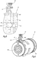
- the module 43 further comprises a drive unit 60 for driving the rod 43.5 in rotation around the axis ZZ.
- this drive unit 60 comprises for example an actuator of the rod 43.5, this actuator being indifferently mechanical, hydraulic or electrical.
- the drive unit 60 is driven by a control unit 62 able to send an ad hoc control signal, indicated by the arrow S2 on the figure 1 .
- This control unit 62 receives the signal S1 coming from the viscosity measuring sensor 43.2 and is designed to process this signal S1 so as to deduce therefrom the control signal S2 sent to the drive unit 60.
- the unit 62 controls, after processing of the signal S1, the pivoted position of the flap 43.4 and therefore the passage section of the flow channel 43A.
- the control unit 62 slaves the passage section of the flow channel 43A according to the measurement provided by the sensor 43.2. There is thus a looping between the measurement of the viscosity of the flow of material inside the extrusion machine 1 and the passage section for this material in the extrusion machine, more precisely in the flow channel. 43A.
- a method of controlling the extrusion machine 1 described so far with regard to Figures 1 to 4 is the next. While a material to be extruded is processed by the extrusion machine 1, the ingredient or ingredients of this material being introduced inside the sheath 10 via its elements 11 and 12, the viscosity of this material being extruded is measured continuously in the flow of the material inside the extrusion machine 1, more precisely in the flow of the material inside the module 43, thanks to the sensor 43.2.
- the extrusion machine 1 is controlled to control the filling rate of the sheath 10 by the material, by adjusting the passage section for the material in the extrusion machine, more precisely by adjusting the passage section of the flow channel 43A by varying this passage section by the flap 43.4.
- the pivoted position of the flap 43.4 is controlled by the unit 62, via the drive unit 60 and the rod 43.5.
- the sensor 43.2 measures, in real time, the viscosity changes generated by the variation imposed by the flap 43.4 on the passage section of the flow channel 43A, thus allowing closed-loop regulation between this flap 43.4 and this sensor 43.2.
- control unit 62 In practice, the calculations implemented by the control unit 62 to provide this regulation are not limiting of the invention. As an example of servo control, effective and easy to implement, the control unit 62 is designed to maintain substantially constant the viscosity measured by the sensor 43.2, the viscosity value that it is desired to maintain unchanged. being previously supplied to this unit, for example by previously knowing an image of the "ideal" viscosity value for the material extruded by the extrusion machine 1.
- a variant of the control method of this extrusion machine is to adjust the passage section for the material in the extrusion machine manually.
- the corresponding extrusion machine differs from the extrusion machine 1 shown on the Figures 1 to 4 by the withdrawal of the unit from slave control 62 and by replacing the motorized drive unit 60 by a member 60 'for manually controlling the position of the rod 43.5 in rotation about the axis ZZ and therefore the pivoted position of the flap 43.4, as represented on the Figures 5 and 6 .
- a human operator has the information corresponding to the signal S1 supplied by the viscosity measuring sensor 43.2, for example by means of a display, and, depending on this information, the operator actuates the hand, thanks to the organ 60 ', the rod 43.5.
- the end of this rod, emerging outside the casing 43.1 is advantageously provided with a position indicator 61 'associated with a graduated marking 61'A worn by the outer face of the casing 43.1 or the support 43.6.
- a variant of the process described up to now consists in measuring the viscosity in line not at the level of the outlet device 40, but at one of the elements 11 to 15 of the sleeve 10, in particular the most downstream element. 15.
- the viscosity measured permanently is not that of the material leaving the sheath, but that of the material in the sheath, especially in the downstream portion of this sheath.
- the extrusion machine is, in a manner not shown in the figures, arranged accordingly: for example, a viscosity sensor, similar to the sensor 43.2, is arranged in the bore of the sleeve, in particular at the level of a zone of the screws 20, in which its or their thread is locally reduced or eliminated in favor of a substantially smooth surface.
- the extrusion machine according to the invention comprises means for measuring in-line the viscosity, that is to say means making it possible to measure, in the flow of the material, flowing in its sleeve or in its output device, or both, for, for example, reasons of safety of measurement or adaptability of the extrusion machine, the viscosity of this material.
Landscapes
- Engineering & Computer Science (AREA)
- Mechanical Engineering (AREA)
- Extrusion Moulding Of Plastics Or The Like (AREA)
- General Preparation And Processing Of Foods (AREA)
- Processing And Handling Of Plastics And Other Materials For Molding In General (AREA)
Applications Claiming Priority (2)
| Application Number | Priority Date | Filing Date | Title |
|---|---|---|---|
| FR1550835A FR3032143B1 (fr) | 2015-02-03 | 2015-02-03 | Procede de controle-commande d'une machine d'extrusion, ainsi que machine d'extrusion |
| PCT/EP2016/052139 WO2016124570A1 (fr) | 2015-02-03 | 2016-02-02 | Procédé de contrôle-commande d'une machine d'extrusion bi-vis, ainsi que machine d'extrusion bi-vis |
Publications (2)
| Publication Number | Publication Date |
|---|---|
| EP3253552A1 EP3253552A1 (fr) | 2017-12-13 |
| EP3253552B1 true EP3253552B1 (fr) | 2019-06-26 |
Family
ID=52824481
Family Applications (1)
| Application Number | Title | Priority Date | Filing Date |
|---|---|---|---|
| EP16703468.5A Active EP3253552B1 (fr) | 2015-02-03 | 2016-02-02 | Procédé de contrôle-commande d'une machine d'extrusion bi-vis, ainsi que machine d'extrusion bi-vis |
Country Status (12)
| Country | Link |
|---|---|
| US (1) | US20180022007A1 (https=) |
| EP (1) | EP3253552B1 (https=) |
| JP (1) | JP6669777B2 (https=) |
| AU (1) | AU2016214509A1 (https=) |
| BR (1) | BR112017016563A2 (https=) |
| CA (1) | CA2975023A1 (https=) |
| CL (1) | CL2017001962A1 (https=) |
| DK (1) | DK3253552T3 (https=) |
| ES (1) | ES2743518T3 (https=) |
| FR (1) | FR3032143B1 (https=) |
| RU (1) | RU2696607C2 (https=) |
| WO (1) | WO2016124570A1 (https=) |
Families Citing this family (4)
| Publication number | Priority date | Publication date | Assignee | Title |
|---|---|---|---|---|
| JP7597598B2 (ja) * | 2021-02-02 | 2024-12-10 | 株式会社日本製鋼所 | 押出装置および樹脂製品の製造方法 |
| DE102021112618A1 (de) * | 2021-05-14 | 2022-11-17 | Windmöller & Hölscher Kg | Verfahren zur Herstellung einer Kunststofffolie in einer Folienextrusionsmaschine aus einer Gesamtmenge an Rohstoffen sowie Computerprogrammprodukt zur Durchführung des Verfahrens |
| CN114654696B (zh) * | 2022-04-13 | 2023-08-29 | 三杰节能新材料股份有限公司 | 一种大型聚乙烯保温外护弯管加工时的温控机构 |
| CN119141828B (zh) * | 2024-11-19 | 2025-01-21 | 寿光市富鑫塑胶助剂有限公司 | 一种挤出机挤出通道内消泡母粒混合料检测设备 |
Family Cites Families (13)
| Publication number | Priority date | Publication date | Assignee | Title |
|---|---|---|---|---|
| JPH069814B2 (ja) * | 1988-09-28 | 1994-02-09 | 株式会社日本製鋼所 | 2軸押出機の混練度調整装置 |
| JPH07119032B2 (ja) * | 1991-06-28 | 1995-12-20 | 株式会社メカトロ常磐インターナショナル | 射出成形機等における流体の射出方法並びにこの射出方法に使用する温度と圧力の測定方法 |
| DE4325514C1 (de) * | 1993-07-29 | 1994-10-27 | Schaaf Technologie Gmbh | Kochextruder zur Herstellung von thermisch behandelten Biopolymeren sowie Verfahren zum Kochextrudieren von Biopolymeren |
| JPH0780913A (ja) * | 1993-09-17 | 1995-03-28 | Plast Kogaku Kenkyusho:Kk | 熱可塑性合成樹脂シートの押出成形装置 |
| CH687047A5 (de) * | 1993-11-30 | 1996-08-30 | Hler Ag B | Verfahren zur Regelung einer Arbeitsmaschine |
| JPH1148309A (ja) * | 1997-08-01 | 1999-02-23 | Japan Steel Works Ltd:The | 二軸押出機の混練調整方法及び装置 |
| JP2002079515A (ja) * | 2000-09-07 | 2002-03-19 | Calp Corp | 熱可塑性樹脂組成物及びゴム組成物の製造方法 |
| JP3929340B2 (ja) * | 2002-03-29 | 2007-06-13 | 株式会社カワタ | タンデム型押出成形装置 |
| US6691558B1 (en) * | 2002-07-31 | 2004-02-17 | General Electric Company | In-line rheometer device and method |
| JP4532374B2 (ja) * | 2005-09-15 | 2010-08-25 | 株式会社日本製鋼所 | 熱可塑性樹脂発泡体の製造方法および製造装置 |
| JP5560450B2 (ja) * | 2010-09-01 | 2014-07-30 | 株式会社神戸製鋼所 | 混練押出機での粘度調整方法、および、混練押出機 |
| JP2013209545A (ja) * | 2012-03-30 | 2013-10-10 | Sekisui Plastics Co Ltd | 押出発泡用樹脂組成物、樹脂発泡体の製造方法及び樹脂発泡体 |
| CN203697456U (zh) * | 2013-12-30 | 2014-07-09 | 南京金杉汽车工程塑料有限责任公司 | 一种新型共混聚丙烯流体粘度自动控制系统 |
-
2015
- 2015-02-03 FR FR1550835A patent/FR3032143B1/fr not_active Expired - Fee Related
-
2016
- 2016-02-02 US US15/547,927 patent/US20180022007A1/en not_active Abandoned
- 2016-02-02 BR BR112017016563-5A patent/BR112017016563A2/pt not_active Application Discontinuation
- 2016-02-02 CA CA2975023A patent/CA2975023A1/fr not_active Abandoned
- 2016-02-02 WO PCT/EP2016/052139 patent/WO2016124570A1/fr not_active Ceased
- 2016-02-02 AU AU2016214509A patent/AU2016214509A1/en not_active Abandoned
- 2016-02-02 DK DK16703468.5T patent/DK3253552T3/da active
- 2016-02-02 EP EP16703468.5A patent/EP3253552B1/fr active Active
- 2016-02-02 ES ES16703468T patent/ES2743518T3/es active Active
- 2016-02-02 RU RU2017127060A patent/RU2696607C2/ru not_active IP Right Cessation
- 2016-02-02 JP JP2017558785A patent/JP6669777B2/ja not_active Expired - Fee Related
-
2017
- 2017-08-01 CL CL2017001962A patent/CL2017001962A1/es unknown
Non-Patent Citations (1)
| Title |
|---|
| None * |
Also Published As
| Publication number | Publication date |
|---|---|
| US20180022007A1 (en) | 2018-01-25 |
| JP6669777B2 (ja) | 2020-03-18 |
| CA2975023A1 (fr) | 2016-08-11 |
| ES2743518T3 (es) | 2020-02-19 |
| DK3253552T3 (da) | 2019-09-02 |
| WO2016124570A1 (fr) | 2016-08-11 |
| CL2017001962A1 (es) | 2018-04-20 |
| RU2017127060A3 (https=) | 2019-06-03 |
| RU2696607C2 (ru) | 2019-08-09 |
| RU2017127060A (ru) | 2019-01-28 |
| EP3253552A1 (fr) | 2017-12-13 |
| BR112017016563A2 (pt) | 2018-04-10 |
| FR3032143A1 (fr) | 2016-08-05 |
| FR3032143B1 (fr) | 2017-08-25 |
| AU2016214509A1 (en) | 2017-08-17 |
| JP2018508391A (ja) | 2018-03-29 |
Similar Documents
| Publication | Publication Date | Title |
|---|---|---|
| EP3253552B1 (fr) | Procédé de contrôle-commande d'une machine d'extrusion bi-vis, ainsi que machine d'extrusion bi-vis | |
| EP4185460B1 (fr) | Filière pour l'extrusion d'une matière riche en protéines et en eau, ainsi que machine d'extrusion comportant une telle filière | |
| EP1882578B1 (fr) | Dispositif et procédé de gainage de câblé et le câble manufacturé | |
| FR2730380A1 (fr) | Procede de preparation en continu d'un fromage ou d'une specialite fromagere, installations pour la mise en oeuvre du procede et produit obtenu par le procede | |
| US6561011B2 (en) | Apparatus and method for measuring the viscosity of plastic materials | |
| EP4376641B1 (fr) | Système de préparation en continu d'un produit alimentaire extrudé à partir d'une matière riche en protéines et en eau | |
| EP0169126A1 (fr) | Procédé de traitement de matière par extrusion et installation de fabrication d'un produit alimentaire composite | |
| FR2572899A1 (fr) | Procede et installation de fabrication d'un produit fourre | |
| EP0240699B1 (fr) | Filière d'extrusion pour faire des produits plats | |
| FR2932956A1 (fr) | Procede pour la mise en forme d'un produit alimentaire par cryoextrusion mettant en oeuvre une regulation de temperature predictive. | |
| CA1077220A (fr) | Dispositif de filieres pour la production de feuilles ou pellicules composites | |
| EP2904266B1 (fr) | Pompe à liquide volumètrique chauffante | |
| CH624486A5 (https=) | ||
| EP3160710B1 (fr) | Procédé et dispositif de fabrication de fil métallique enrobé de caoutchouc | |
| EP4623707A1 (fr) | Filière pour l extrusion d'une matière riche en protéines et en eau, ainsi que système de préparation en continu d'un produit alimentaire extrudé, comprenant une telle filière | |
| EP0781511B1 (fr) | Tête de compression de machine de production de pâte à mâcher | |
| FR2572013A1 (fr) | Filiere de fabrication de granules de matiere extrudee | |
| WO2018069632A1 (fr) | Extrudeuse et procede d'extrusion d'un melange d'elastomeres | |
| FR2478524A1 (fr) | Installation pour le malaxage de matieres plastiques | |
| FR2889818A1 (fr) | Extrudeuse a entrefer reglable et vis d'extrusion decouvrable | |
| FR2572898A1 (fr) | Procede et installation de fabrication par extrusion d'un produit alimentaire composite | |
| FR2686695A1 (fr) | Module rheometrique applicable a un dispositif pour l'injection de materiaux thermoplastiques ou thermodurcissables. | |
| FR2978934A1 (fr) | Vis d'extrudeuse du type a saillies | |
| BE539056A (https=) | ||
| BE405359A (https=) |
Legal Events
| Date | Code | Title | Description |
|---|---|---|---|
| STAA | Information on the status of an ep patent application or granted ep patent |
Free format text: STATUS: THE INTERNATIONAL PUBLICATION HAS BEEN MADE |
|
| PUAI | Public reference made under article 153(3) epc to a published international application that has entered the european phase |
Free format text: ORIGINAL CODE: 0009012 |
|
| STAA | Information on the status of an ep patent application or granted ep patent |
Free format text: STATUS: REQUEST FOR EXAMINATION WAS MADE |
|
| 17P | Request for examination filed |
Effective date: 20170802 |
|
| AK | Designated contracting states |
Kind code of ref document: A1 Designated state(s): AL AT BE BG CH CY CZ DE DK EE ES FI FR GB GR HR HU IE IS IT LI LT LU LV MC MK MT NL NO PL PT RO RS SE SI SK SM TR |
|
| AX | Request for extension of the european patent |
Extension state: BA ME |
|
| DAV | Request for validation of the european patent (deleted) | ||
| DAX | Request for extension of the european patent (deleted) | ||
| REG | Reference to a national code |
Ref country code: DE Ref legal event code: R079 Ref document number: 602016015888 Country of ref document: DE Free format text: PREVIOUS MAIN CLASS: B29C0047080000 Ipc: B29C0048920000 |
|
| GRAP | Despatch of communication of intention to grant a patent |
Free format text: ORIGINAL CODE: EPIDOSNIGR1 |
|
| STAA | Information on the status of an ep patent application or granted ep patent |
Free format text: STATUS: GRANT OF PATENT IS INTENDED |
|
| RIC1 | Information provided on ipc code assigned before grant |
Ipc: B29C 48/255 20190101ALI20190110BHEP Ipc: B29C 48/40 20190101ALI20190110BHEP Ipc: B29C 48/92 20190101AFI20190110BHEP |
|
| INTG | Intention to grant announced |
Effective date: 20190201 |
|
| GRAS | Grant fee paid |
Free format text: ORIGINAL CODE: EPIDOSNIGR3 |
|
| GRAA | (expected) grant |
Free format text: ORIGINAL CODE: 0009210 |
|
| STAA | Information on the status of an ep patent application or granted ep patent |
Free format text: STATUS: THE PATENT HAS BEEN GRANTED |
|
| AK | Designated contracting states |
Kind code of ref document: B1 Designated state(s): AL AT BE BG CH CY CZ DE DK EE ES FI FR GB GR HR HU IE IS IT LI LT LU LV MC MK MT NL NO PL PT RO RS SE SI SK SM TR |
|
| REG | Reference to a national code |
Ref country code: GB Ref legal event code: FG4D Free format text: NOT ENGLISH |
|
| REG | Reference to a national code |
Ref country code: CH Ref legal event code: EP |
|
| REG | Reference to a national code |
Ref country code: AT Ref legal event code: REF Ref document number: 1147789 Country of ref document: AT Kind code of ref document: T Effective date: 20190715 |
|
| REG | Reference to a national code |
Ref country code: DE Ref legal event code: R096 Ref document number: 602016015888 Country of ref document: DE |
|
| REG | Reference to a national code |
Ref country code: IE Ref legal event code: FG4D Free format text: LANGUAGE OF EP DOCUMENT: FRENCH |
|
| REG | Reference to a national code |
Ref country code: CH Ref legal event code: NV Representative=s name: MICHELI AND CIE SA, CH |
|
| REG | Reference to a national code |
Ref country code: DK Ref legal event code: T3 Effective date: 20190816 |
|
| REG | Reference to a national code |
Ref country code: DK Ref legal event code: T3 Effective date: 20190829 |
|
| REG | Reference to a national code |
Ref country code: NL Ref legal event code: FP |
|
| PG25 | Lapsed in a contracting state [announced via postgrant information from national office to epo] |
Ref country code: AL Free format text: LAPSE BECAUSE OF FAILURE TO SUBMIT A TRANSLATION OF THE DESCRIPTION OR TO PAY THE FEE WITHIN THE PRESCRIBED TIME-LIMIT Effective date: 20190626 Ref country code: HR Free format text: LAPSE BECAUSE OF FAILURE TO SUBMIT A TRANSLATION OF THE DESCRIPTION OR TO PAY THE FEE WITHIN THE PRESCRIBED TIME-LIMIT Effective date: 20190626 Ref country code: LT Free format text: LAPSE BECAUSE OF FAILURE TO SUBMIT A TRANSLATION OF THE DESCRIPTION OR TO PAY THE FEE WITHIN THE PRESCRIBED TIME-LIMIT Effective date: 20190626 Ref country code: SE Free format text: LAPSE BECAUSE OF FAILURE TO SUBMIT A TRANSLATION OF THE DESCRIPTION OR TO PAY THE FEE WITHIN THE PRESCRIBED TIME-LIMIT Effective date: 20190626 Ref country code: FI Free format text: LAPSE BECAUSE OF FAILURE TO SUBMIT A TRANSLATION OF THE DESCRIPTION OR TO PAY THE FEE WITHIN THE PRESCRIBED TIME-LIMIT Effective date: 20190626 |
|
| REG | Reference to a national code |
Ref country code: LT Ref legal event code: MG4D Ref country code: NO Ref legal event code: T2 Effective date: 20190626 |
|
| PG25 | Lapsed in a contracting state [announced via postgrant information from national office to epo] |
Ref country code: LV Free format text: LAPSE BECAUSE OF FAILURE TO SUBMIT A TRANSLATION OF THE DESCRIPTION OR TO PAY THE FEE WITHIN THE PRESCRIBED TIME-LIMIT Effective date: 20190626 Ref country code: RS Free format text: LAPSE BECAUSE OF FAILURE TO SUBMIT A TRANSLATION OF THE DESCRIPTION OR TO PAY THE FEE WITHIN THE PRESCRIBED TIME-LIMIT Effective date: 20190626 Ref country code: BG Free format text: LAPSE BECAUSE OF FAILURE TO SUBMIT A TRANSLATION OF THE DESCRIPTION OR TO PAY THE FEE WITHIN THE PRESCRIBED TIME-LIMIT Effective date: 20190926 |
|
| REG | Reference to a national code |
Ref country code: AT Ref legal event code: MK05 Ref document number: 1147789 Country of ref document: AT Kind code of ref document: T Effective date: 20190626 |
|
| REG | Reference to a national code |
Ref country code: GR Ref legal event code: EP Ref document number: 20190402763 Country of ref document: GR Effective date: 20191128 |
|
| PG25 | Lapsed in a contracting state [announced via postgrant information from national office to epo] |
Ref country code: PT Free format text: LAPSE BECAUSE OF FAILURE TO SUBMIT A TRANSLATION OF THE DESCRIPTION OR TO PAY THE FEE WITHIN THE PRESCRIBED TIME-LIMIT Effective date: 20191028 Ref country code: SK Free format text: LAPSE BECAUSE OF FAILURE TO SUBMIT A TRANSLATION OF THE DESCRIPTION OR TO PAY THE FEE WITHIN THE PRESCRIBED TIME-LIMIT Effective date: 20190626 Ref country code: CZ Free format text: LAPSE BECAUSE OF FAILURE TO SUBMIT A TRANSLATION OF THE DESCRIPTION OR TO PAY THE FEE WITHIN THE PRESCRIBED TIME-LIMIT Effective date: 20190626 Ref country code: AT Free format text: LAPSE BECAUSE OF FAILURE TO SUBMIT A TRANSLATION OF THE DESCRIPTION OR TO PAY THE FEE WITHIN THE PRESCRIBED TIME-LIMIT Effective date: 20190626 Ref country code: RO Free format text: LAPSE BECAUSE OF FAILURE TO SUBMIT A TRANSLATION OF THE DESCRIPTION OR TO PAY THE FEE WITHIN THE PRESCRIBED TIME-LIMIT Effective date: 20190626 Ref country code: EE Free format text: LAPSE BECAUSE OF FAILURE TO SUBMIT A TRANSLATION OF THE DESCRIPTION OR TO PAY THE FEE WITHIN THE PRESCRIBED TIME-LIMIT Effective date: 20190626 |
|
| REG | Reference to a national code |
Ref country code: ES Ref legal event code: FG2A Ref document number: 2743518 Country of ref document: ES Kind code of ref document: T3 Effective date: 20200219 |
|
| PG25 | Lapsed in a contracting state [announced via postgrant information from national office to epo] |
Ref country code: SM Free format text: LAPSE BECAUSE OF FAILURE TO SUBMIT A TRANSLATION OF THE DESCRIPTION OR TO PAY THE FEE WITHIN THE PRESCRIBED TIME-LIMIT Effective date: 20190626 Ref country code: IS Free format text: LAPSE BECAUSE OF FAILURE TO SUBMIT A TRANSLATION OF THE DESCRIPTION OR TO PAY THE FEE WITHIN THE PRESCRIBED TIME-LIMIT Effective date: 20191026 |
|
| PG25 | Lapsed in a contracting state [announced via postgrant information from national office to epo] |
Ref country code: PL Free format text: LAPSE BECAUSE OF FAILURE TO SUBMIT A TRANSLATION OF THE DESCRIPTION OR TO PAY THE FEE WITHIN THE PRESCRIBED TIME-LIMIT Effective date: 20190626 |
|
| PGFP | Annual fee paid to national office [announced via postgrant information from national office to epo] |
Ref country code: IT Payment date: 20200211 Year of fee payment: 5 |
|
| PG25 | Lapsed in a contracting state [announced via postgrant information from national office to epo] |
Ref country code: IS Free format text: LAPSE BECAUSE OF FAILURE TO SUBMIT A TRANSLATION OF THE DESCRIPTION OR TO PAY THE FEE WITHIN THE PRESCRIBED TIME-LIMIT Effective date: 20200224 |
|
| REG | Reference to a national code |
Ref country code: DE Ref legal event code: R097 Ref document number: 602016015888 Country of ref document: DE |
|
| PGFP | Annual fee paid to national office [announced via postgrant information from national office to epo] |
Ref country code: TR Payment date: 20200121 Year of fee payment: 5 |
|
| PLBE | No opposition filed within time limit |
Free format text: ORIGINAL CODE: 0009261 |
|
| STAA | Information on the status of an ep patent application or granted ep patent |
Free format text: STATUS: NO OPPOSITION FILED WITHIN TIME LIMIT |
|
| PG2D | Information on lapse in contracting state deleted |
Ref country code: IS |
|
| 26N | No opposition filed |
Effective date: 20200603 |
|
| PG25 | Lapsed in a contracting state [announced via postgrant information from national office to epo] |
Ref country code: SI Free format text: LAPSE BECAUSE OF FAILURE TO SUBMIT A TRANSLATION OF THE DESCRIPTION OR TO PAY THE FEE WITHIN THE PRESCRIBED TIME-LIMIT Effective date: 20190626 |
|
| REG | Reference to a national code |
Ref country code: DK Ref legal event code: EBP Effective date: 20200229 |
|
| REG | Reference to a national code |
Ref country code: NO Ref legal event code: MMEP |
|
| REG | Reference to a national code |
Ref country code: NL Ref legal event code: MM Effective date: 20200301 |
|
| GBPC | Gb: european patent ceased through non-payment of renewal fee |
Effective date: 20200202 |
|
| REG | Reference to a national code |
Ref country code: BE Ref legal event code: MM Effective date: 20200229 |
|
| PG25 | Lapsed in a contracting state [announced via postgrant information from national office to epo] |
Ref country code: GR Free format text: LAPSE BECAUSE OF NON-PAYMENT OF DUE FEES Effective date: 20200909 Ref country code: MC Free format text: LAPSE BECAUSE OF FAILURE TO SUBMIT A TRANSLATION OF THE DESCRIPTION OR TO PAY THE FEE WITHIN THE PRESCRIBED TIME-LIMIT Effective date: 20190626 Ref country code: LU Free format text: LAPSE BECAUSE OF NON-PAYMENT OF DUE FEES Effective date: 20200202 Ref country code: NO Free format text: LAPSE BECAUSE OF NON-PAYMENT OF DUE FEES Effective date: 20200229 |
|
| PG25 | Lapsed in a contracting state [announced via postgrant information from national office to epo] |
Ref country code: NL Free format text: LAPSE BECAUSE OF NON-PAYMENT OF DUE FEES Effective date: 20200301 |
|
| PG25 | Lapsed in a contracting state [announced via postgrant information from national office to epo] |
Ref country code: DK Free format text: LAPSE BECAUSE OF NON-PAYMENT OF DUE FEES Effective date: 20200229 Ref country code: IE Free format text: LAPSE BECAUSE OF NON-PAYMENT OF DUE FEES Effective date: 20200202 Ref country code: GB Free format text: LAPSE BECAUSE OF NON-PAYMENT OF DUE FEES Effective date: 20200202 |
|
| PG25 | Lapsed in a contracting state [announced via postgrant information from national office to epo] |
Ref country code: BE Free format text: LAPSE BECAUSE OF NON-PAYMENT OF DUE FEES Effective date: 20200229 |
|
| PG25 | Lapsed in a contracting state [announced via postgrant information from national office to epo] |
Ref country code: ES Free format text: LAPSE BECAUSE OF NON-PAYMENT OF DUE FEES Effective date: 20200203 |
|
| PG25 | Lapsed in a contracting state [announced via postgrant information from national office to epo] |
Ref country code: IT Free format text: LAPSE BECAUSE OF NON-PAYMENT OF DUE FEES Effective date: 20210202 |
|
| PG25 | Lapsed in a contracting state [announced via postgrant information from national office to epo] |
Ref country code: MT Free format text: LAPSE BECAUSE OF FAILURE TO SUBMIT A TRANSLATION OF THE DESCRIPTION OR TO PAY THE FEE WITHIN THE PRESCRIBED TIME-LIMIT Effective date: 20190626 Ref country code: CY Free format text: LAPSE BECAUSE OF FAILURE TO SUBMIT A TRANSLATION OF THE DESCRIPTION OR TO PAY THE FEE WITHIN THE PRESCRIBED TIME-LIMIT Effective date: 20190626 |
|
| PG25 | Lapsed in a contracting state [announced via postgrant information from national office to epo] |
Ref country code: MK Free format text: LAPSE BECAUSE OF FAILURE TO SUBMIT A TRANSLATION OF THE DESCRIPTION OR TO PAY THE FEE WITHIN THE PRESCRIBED TIME-LIMIT Effective date: 20190626 |
|
| P01 | Opt-out of the competence of the unified patent court (upc) registered |
Effective date: 20230516 |
|
| PGFP | Annual fee paid to national office [announced via postgrant information from national office to epo] |
Ref country code: DE Payment date: 20240213 Year of fee payment: 9 Ref country code: CH Payment date: 20240301 Year of fee payment: 9 |
|
| PGFP | Annual fee paid to national office [announced via postgrant information from national office to epo] |
Ref country code: FR Payment date: 20240112 Year of fee payment: 9 |
|
| REG | Reference to a national code |
Ref country code: DE Ref legal event code: R119 Ref document number: 602016015888 Country of ref document: DE |
|
| REG | Reference to a national code |
Ref country code: CH Ref legal event code: PL |
|
| PG25 | Lapsed in a contracting state [announced via postgrant information from national office to epo] |
Ref country code: CH Free format text: LAPSE BECAUSE OF NON-PAYMENT OF DUE FEES Effective date: 20250228 |
|
| PG25 | Lapsed in a contracting state [announced via postgrant information from national office to epo] |
Ref country code: DE Free format text: LAPSE BECAUSE OF NON-PAYMENT OF DUE FEES Effective date: 20250902 |
|
| PG25 | Lapsed in a contracting state [announced via postgrant information from national office to epo] |
Ref country code: FR Free format text: LAPSE BECAUSE OF NON-PAYMENT OF DUE FEES Effective date: 20250228 |