EP3253271B1 - Okular für ein chirurgisches instrument - Google Patents
Okular für ein chirurgisches instrument Download PDFInfo
- Publication number
- EP3253271B1 EP3253271B1 EP16700813.5A EP16700813A EP3253271B1 EP 3253271 B1 EP3253271 B1 EP 3253271B1 EP 16700813 A EP16700813 A EP 16700813A EP 3253271 B1 EP3253271 B1 EP 3253271B1
- Authority
- EP
- European Patent Office
- Prior art keywords
- eyepiece
- holder
- optical flat
- eyepiece device
- endoscope
- Prior art date
- Legal status (The legal status is an assumption and is not a legal conclusion. Google has not performed a legal analysis and makes no representation as to the accuracy of the status listed.)
- Active
Links
- 230000003287 optical effect Effects 0.000 claims description 38
- 230000002093 peripheral effect Effects 0.000 claims description 3
- 230000000295 complement effect Effects 0.000 claims description 2
- 239000011521 glass Substances 0.000 description 33
- 239000005357 flat glass Substances 0.000 description 3
- 230000001154 acute effect Effects 0.000 description 1
- 238000013461 design Methods 0.000 description 1
- 238000001514 detection method Methods 0.000 description 1
- 238000011161 development Methods 0.000 description 1
- 238000011156 evaluation Methods 0.000 description 1
- 239000000835 fiber Substances 0.000 description 1
- 239000003365 glass fiber Substances 0.000 description 1
- 229910052736 halogen Inorganic materials 0.000 description 1
- 150000002367 halogens Chemical class 0.000 description 1
- 238000003384 imaging method Methods 0.000 description 1
- 238000000034 method Methods 0.000 description 1
- 238000002324 minimally invasive surgery Methods 0.000 description 1
- 229910052594 sapphire Inorganic materials 0.000 description 1
- 239000010980 sapphire Substances 0.000 description 1
- 238000012549 training Methods 0.000 description 1
- 230000007704 transition Effects 0.000 description 1
Images

Classifications
-
- A—HUMAN NECESSITIES
- A61—MEDICAL OR VETERINARY SCIENCE; HYGIENE
- A61B—DIAGNOSIS; SURGERY; IDENTIFICATION
- A61B1/00—Instruments for performing medical examinations of the interior of cavities or tubes of the body by visual or photographical inspection, e.g. endoscopes; Illuminating arrangements therefor
- A61B1/00163—Optical arrangements
- A61B1/00195—Optical arrangements with eyepieces
-
- A—HUMAN NECESSITIES
- A61—MEDICAL OR VETERINARY SCIENCE; HYGIENE
- A61B—DIAGNOSIS; SURGERY; IDENTIFICATION
- A61B1/00—Instruments for performing medical examinations of the interior of cavities or tubes of the body by visual or photographical inspection, e.g. endoscopes; Illuminating arrangements therefor
- A61B1/00064—Constructional details of the endoscope body
- A61B1/0011—Manufacturing of endoscope parts
-
- A—HUMAN NECESSITIES
- A61—MEDICAL OR VETERINARY SCIENCE; HYGIENE
- A61B—DIAGNOSIS; SURGERY; IDENTIFICATION
- A61B1/00—Instruments for performing medical examinations of the interior of cavities or tubes of the body by visual or photographical inspection, e.g. endoscopes; Illuminating arrangements therefor
- A61B1/00131—Accessories for endoscopes
- A61B1/00137—End pieces at either end of the endoscope, e.g. caps, seals or forceps plugs
-
- G—PHYSICS
- G02—OPTICS
- G02B—OPTICAL ELEMENTS, SYSTEMS OR APPARATUS
- G02B23/00—Telescopes, e.g. binoculars; Periscopes; Instruments for viewing the inside of hollow bodies; Viewfinders; Optical aiming or sighting devices
- G02B23/24—Instruments or systems for viewing the inside of hollow bodies, e.g. fibrescopes
- G02B23/2407—Optical details
- G02B23/2453—Optical details of the proximal end
-
- G—PHYSICS
- G02—OPTICS
- G02B—OPTICAL ELEMENTS, SYSTEMS OR APPARATUS
- G02B23/00—Telescopes, e.g. binoculars; Periscopes; Instruments for viewing the inside of hollow bodies; Viewfinders; Optical aiming or sighting devices
- G02B23/24—Instruments or systems for viewing the inside of hollow bodies, e.g. fibrescopes
- G02B23/2476—Non-optical details, e.g. housings, mountings, supports
-
- G—PHYSICS
- G02—OPTICS
- G02B—OPTICAL ELEMENTS, SYSTEMS OR APPARATUS
- G02B27/00—Optical systems or apparatus not provided for by any of the groups G02B1/00 - G02B26/00, G02B30/00
- G02B27/0018—Optical systems or apparatus not provided for by any of the groups G02B1/00 - G02B26/00, G02B30/00 with means for preventing ghost images
Definitions
- the invention relates to an eyepiece for a surgical instrument, in particular endoscope or laparoscope, with an eyepiece for an optical assembly, wherein a plane glass is accommodated in a holder and wherein the holder for the flat glass with the eyepiece is connected or connected.
- the invention relates to a surgical instrument, in particular endoscope or laparoscope.
- Minimally invasive endoscopic procedures on the human or animal body are accomplished by elongated shaft endoscopes inserted into a body cavity through an existing or pre-meshed body opening for that purpose. Since a direct view from outside on the surgical field in the body cavity is not possible, known endoscopes allow a view into the body cavity to be treated.
- conventional endoscopes have an optic with one or more lenses at the distal tip of the endoscope shaft directing light from the body cavity into the endoscope.
- the endoscope shaft may include an array of lenses, such as rod lenses, by which light is directed out of the body cavity to the proximal end of the endoscope, ie, the end that is held and operated by a surgeon or surgeon.
- an eyepiece funnel with an eyepiece, ie an optic, from which the light which enters at the distal tip of the endoscope emerges again.
- an eyepiece can be used for direct observation with the naked eye, which is brought to the Okulartrichter.
- JP S60 15618 A discloses an eyepiece with a plane glass according to the preamble of independent claim 1. Based on this prior art, the object of the invention is in surgical instruments, a reflection-free detection of images, in particular by means of an image sensor unit to allow, the design effort as possible should be kept low.
- an eyepiece device for a surgical instrument in particular endoscope or laparoscope
- an eyepiece for an optical assembly wherein a plane glass is accommodated in a holder and wherein the eyepiece is connectable or connected to the holder for the plane glass, thereby is further developed that the plano glass a common side edge is provided with a contact surface for the eyepiece and a contact surface for the holder, wherein the surface normal of the Planglases and the Okular charged facing contact surface of the Planglases, preferably when receiving the Planglases in the holder at an angle not equal to 0 °, preferably at an angle between 2.0 ° to 10.0 °, are aligned with each other.
- the invention is based on the idea that, in the case of the ocular device of a surgical instrument, the surface normal of the plane lens which faces the eyepiece mount, with respect to the optical axis of the optical assembly received in the eyepiece mount, is at an angle not equal to 0 ° (ie, 0 °). ie not parallel to each other, is aligned.
- the inlet side and the outlet side or the surfaces of the Planglases are aligned with respect to the vertical plane to the optical axis of the eyepiece at an angle not equal to 0 °, whereby upon passage of light rays through the plane glass or the eyepiece no reflections within the Planglases arise and avoid possible artifacts due to (light) reflections in an image capture sensor.
- plano glass when the Planglases in the eyepiece is arranged by the widened side edge of the Planglases a contact surface is provided on the plano glass, which is aligned perpendicular to the optical or mechanical axis of the eyepiece or to the optical axis of the optical assembly of the eyepiece.
- the plane glass is designed as a flat eyepiece for the eyepiece and has two parallel surfaces through which the light rays pass.
- the surfaces of the Planglases each have a corresponding surface normal, which are perpendicular to the flat surface of the Planglases.
- the plane glass is made of sapphire.
- the planned eyepiece plano glass is preferably with a peripheral widened side edge is formed, wherein provided by the side edge bearing surface for the eyepiece is aligned at an angle to the surfaces of the Planglases, which corresponds to the angle between the surface normal of the Planglases and the optical axis of the received in the Okular charged optical assembly.
- a flat stop shoulder for the plane glass is formed, wherein the mutually parallel surfaces of the Planglases are arranged obliquely to the otherwise vertical orientation of the Planglases (according to the prior art).
- the widened side edge of the Planglases is in this case formed as a plane stop shoulder, wherein the planar stop shoulder is formed as a widened side edge at an acute angle to one or both surfaces of the Planglases.
- the surface normal or surface normal of the Planglases and the Okular charged facing contact surface of the Planglases at an angle between 4.0 ° to 8.0 °, in particular at an angle of 6 ° are aligned. Accordingly, the widened side edge of the Planglases with the contact surface for the eyepiece is formed at an angle of 4.0 ° to 8.0 °, in particular at an angle of 6 °, for example, to the surface at the distal entrance side of the Planglases.
- the widened, preferably circumferential, side edge of the Planglases or the eyepiece is positively and functionally complementary recorded in a receptacle of the holder.
- the plane glass can be cylindrical in one embodiment.
- the widened side edge of the Planglases is ring-shaped.
- the holder is preferably designed as a union nut, preferably with an internal thread.
- the holder provided as a union nut with an internal thread cooperates with an external thread on the eyepiece mount.
- the optical assembly accommodated in the eyepiece mount has one or more lenses and optionally further optical elements.
- the holder is made of plastic, wherein the holder in the training as a union nut has an inner bevel suitable for plane glass, which covers and compensates for a projection of the Planglases or eyepiece glass.
- an embodiment of the eyepiece is characterized in that the holder, in particular cap nut, is formed on the side facing away from the plane glass with a trough.
- the eyepiece device of the surgical instrument that the eyepiece facing away from, ie proximal side of the Planglases flush with the plane glass surrounding area or edge region of the holder, in particular with the peripheral glass surrounding the edge portion of the trough of the holder is aligned.
- an ocular funnel is arranged or can be arranged on the holder.
- the ocular funnel is screwed, for example, to the housing for the ocular socket, wherein the ocular funnel is adapted on the inside to the holder or the union nut and is furthermore preferably formed with a recess for a radial seal (for example for an O-ring).
- the object is achieved by a surgical instrument, in particular endoscope or laparoscope, which is formed with an eyepiece device described above.
- a surgical instrument in particular endoscope or laparoscope, which is formed with an eyepiece device described above.
- an eyepiece device according to the invention, reflections in the plane glass during recording with an image sensor device as well as ghost images due to reflections through the eyepiece window or the proximal plane glass of the eyepiece are avoided.
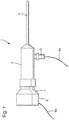
- Fig. 1 shows a schematic side view of an endoscope 1 having at the distal end a tubular shaft 2 with an optic.
- This tubular shaft 2 is inserted through a body opening into a body cavity during a minimally invasive procedure or a minimally invasive examination.
- the tubular shaft 2 opens into a housing 3, which in turn opens at the proximal end, ie at the end, which is arranged towards the surgeon or surgeon, in an eyepiece funnel 4 with an eyepiece, not shown.
- the housing 3 also serves to handle the endoscope 1.
- a light source 5 in particular an LED light source is arranged, which introduces bright light from the side into the optics of the endoscope 1, from where the light introduced at the distal end, ie at the top of the tubular shaft 2 exits to illuminate a surgical field.
- the light source 5 has a connection cable 5a.
- the light source 5 may be an adapter act, to which a fiber optic bundle is attached as a connection cable 5a. The light supplied by the glass fiber bundle is then introduced into the endoscope 1 by means of the adapter.
- it may be an active light source 5, for example based on LEDs, halogen bulbs or the like, in which case the connection cable 5a is a power supply cable.
- a schematically illustrated camera head 6 is arranged with an eyepiece adapter, not shown, which detects the emerging from the eyepiece of the endoscope 1 light with its own optics and focused on an optical surface sensor, such as a CCD chip.
- an optical surface sensor such as a CCD chip.
- Fig. 2 schematically a cross section through an eyepiece on the proximal end of the endoscope is shown in section.
- the eyepiece has an eyepiece 12, in which, for example (not shown here) imaging lenses are arranged as an optical assembly.
- the eyepiece has an optical axis 13 of the optical assembly.
- a plane glass 14 is arranged as eyepiece, which is accommodated in a provided with a recess union nut 16.
- the union nut 16 has an internal thread which cooperates with an external thread of the eyepiece holder 12.
- an eyepiece funnel 18 is arranged on the proximal side of the endoscope on the eyepiece mount 12, which has a hopper trough 19.
- the planing glass 14 held by the union nut 16 has a light entry side 15.1 and a light exit side 15.2, which are aligned parallel to one another.
- the light entrance side 15.1 and the light exit side 15.2 are aligned at an angle ⁇ 90 ° to the optical axis 13.
- the optical axis 13 is collinear with the mechanical axis of the eyepiece.
- the plane glass 14 has a holding shoulder 17. Due to the circumferential holding shoulder 17 as a plane stop shoulder, a plane surface is provided for engagement with the proximal opening of the eyepiece holder 12.
- the retaining shoulder 17 is here aligned at an angle of 6 ° to the plane of the light entrance side 15.1 or to the light exit side 15.2 of the plane glass 14.
- the surface normals of the parallel light entrance side 15.1 and light exit side 15.2 of the plane glass 14 are aligned at an angle of 6 ° to the optical axis 13.
- FIG. 3 schematically an enlarged view of the Planglases 14 of the invention is shown.
- the contact shoulder pointing from the retaining shoulder 17 to the eyepiece mount 12 in this case is a plane surface which is aligned perpendicular to the optical axis 13 or to the mechanical axis of the eyepiece mount.
- the proximal contact surface of the retaining shoulder 17 is arranged in a form-complementary recess of the union nut 16.
- the cap nut 16 is preferably made of plastic and further preferably has a light exit side of the 15.2 Planglases 14 formed inner slope, whereby the union nut 16 has a recess 21 on the proximal side.
- the union nut 16 is formed on the proximal side so that the trough 21 are aligned flush with the region adjacent to the plane glass 14 and the proximal surface, ie the light exit side 15.2 of the flat glass 14.
Landscapes
- Physics & Mathematics (AREA)
- Health & Medical Sciences (AREA)
- Life Sciences & Earth Sciences (AREA)
- Surgery (AREA)
- Optics & Photonics (AREA)
- Engineering & Computer Science (AREA)
- Medical Informatics (AREA)
- General Health & Medical Sciences (AREA)
- Pathology (AREA)
- Nuclear Medicine, Radiotherapy & Molecular Imaging (AREA)
- Biomedical Technology (AREA)
- Heart & Thoracic Surgery (AREA)
- Biophysics (AREA)
- Molecular Biology (AREA)
- Animal Behavior & Ethology (AREA)
- Radiology & Medical Imaging (AREA)
- Public Health (AREA)
- Veterinary Medicine (AREA)
- General Physics & Mathematics (AREA)
- Astronomy & Astrophysics (AREA)
- Manufacturing & Machinery (AREA)
- Endoscopes (AREA)
- Instruments For Viewing The Inside Of Hollow Bodies (AREA)
- Lenses (AREA)
Description
- Die Erfindung betrifft eine Okulareinrichtung für ein chirurgisches Instrument, insbesondere Endoskop oder Laparoskop, mit einer Okularfassung für eine optische Baugruppe, wobei ein Planglas in einer Halterung aufgenommen ist und wobei die Halterung für das Planglas mit der Okularfassung verbindbar oder verbunden ist.
- Außerdem betrifft die Erfindung ein chirurgisches Instrument, insbesondere Endoskop oder Laparoskop.
- Minimal-invasive endoskopische Eingriffe am menschlichen oder tierischen Körper erfolgen mittels Endoskopen mit langgestrecktem bzw. längserstrecktem Schaft, die durch eine vorhandene oder vor dem Eingriff zu diesem Zweck erzeugte Körperöffnung in einen Körperinnen- bzw. -hohlraum eingeführt werden. Da eine direkte Sicht von außen auf das Operationsfeld im Körperhohlraum nicht möglich ist, erlauben bekannte Endoskope einen Blick in den zu behandelnden Körperhohlraum. Hierzu weisen übliche Endoskope eine Optik mit einer oder mehreren Linsen an der distalen Spitze des Endoskopschafts auf, die Licht aus dem Körperhohlraum in das Endoskop hinein lenken. Der Endoskopschaft kann eine Anordnung von Linsen, beispielsweise Stablinsen, aufweisen, mittels denen Licht aus dem Körperhohlraum hinaus zum proximalen Ende des Endoskops geleitet wird, d.h. zu dem Ende, das von einem Operateur oder Chirurgen gehalten und bedient wird.
Im proximalen Bereich des Endoskops, beispielsweise an einem Griff, befindet sich ein Okulartrichter mit einem Okular, also einer Optik, aus der das Licht, das an der distalen Spitze des Endoskops eintritt, wieder austritt. Ein solches Okular kann zur direkten Beobachtung mit bloßem Auge verwendet werden, das an den Okulartrichter herangeführt wird. Das DokumentJP S60 15618 A
Gelöst wird diese Aufgabe durch eine Okulareinrichtung für ein chirurgisches Instrument, insbesondere Endoskop oder Laparoskop, mit einer Okularfassung für eine optische Baugruppe, wobei ein Planglas in einer Halterung aufgenommen ist und wobei die Okularfassung mit der Halterung für das Planglas verbindbar oder verbunden ist, die dadurch weitergebildet wird, dass am Planglas ein verbreiteter Seitenrand mit einer Anlagefläche für die Okularfassung und einer Anlagefläche für die Halterung vorgesehen ist, wobei die Oberflächennormale des Planglases und die der Okularfassung zugewandte Anlagefläche des Planglases, vorzugsweise bei Aufnahme des Planglases in der Halterung, in einem Winkel ungleich 0°, vorzugsweise in einem Winkel zwischen 2,0° bis 10,0°, zueinander ausgerichtet sind. - Die Erfindung beruht auf dem Gedanken, dass bei der Okulareinrichtung eines chirurgischen Instruments die Oberflächennormale des Planglases, die der Okularfassung zugewandt ist, in Bezug auf die optische Achse der in der Okularfassung aufgenommenen optischen Baugruppe in einem Winkel ungleich 0° (d.h. ≠ 0°), d.h. nicht parallel zueinander, ausgerichtet wird. Hierdurch werden die Eintrittsseite und die Austrittsseite bzw. die Oberflächen des Planglases in Bezug auf die senkrechte Ebene zur optischen Achse der Okulareinrichtung in einem Winkel ungleich 0° ausgerichtet, wodurch bei Durchtritt von Lichtstrahlen durch das Planglas bzw. das Okularglas keine Reflektionen innerhalb des Planglases entstehen und mögliche Artefakte aufgrund von (Licht-)Reflektionen in einem Bilderfassungssensor vermieden werden.
- Ferner ist es dabei vorgesehen, dass bei Anordnung des Planglases in der Okularfassung durch den verbreiterten Seitenrand des Planglases eine Anlagefläche am Planglas vorgesehen ist, die senkrecht zur optischen bzw. mechanischen Achse der Okularfassung bzw. zur optischen Achse der optischen Baugruppe der Okularfassung ausgerichtet ist.
- Das Planglas ist als flaches Okularfenster für das Okular ausgebildet und weist zwei parallele Oberflächen auf, durch die die Lichtstrahlen hindurchtreten. Die Oberflächen des Planglases weisen jeweils eine entsprechende Oberflächennormale auf, die senkrecht zur planen Oberfläche des Planglases sind. Vorzugsweise ist das Planglas aus Saphir herstellt.
- Das als Okularfenster vorgesehene Planglas ist vorzugsweise mit einem umlaufenden verbreiterten Seitenrand ausgebildet, wobei die durch den Seitenrand bereitgestellte Anlagefläche für die Okularfassung in einem Winkel zu den Oberflächen des Planglases ausgerichtet ist, der dem Winkel zwischen der Oberflächennormale des Planglases und der optischen Achse der in der Okularfassung aufgenommenen optischen Baugruppe entspricht.
- Bei Anordnung des Planglases an der mit einer optischen Baugruppe versehenen Okularfassung ist eine plane Anschlagschulter für das Planglas ausgebildet, wobei die parallel zueinander ausgerichteten Oberflächen des Planglases schräg zur ansonsten senkrechten Ausrichtung des Planglases (gemäß dem Stand der Technik) angeordnet werden. Der verbreiterte Seitenrand des Planglases ist hierbei als plane Anschlagschulter ausgebildet, wobei die plane Anschlagschulter als verbreiterter Seitenrand in einem spitzen Winkel zu einer oder beiden Oberflächen des Planglases ausgebildet ist.
- Dazu ist in einer Weiterbildung vorgesehen, dass die Oberflächennormale oder Oberflächennormalen des Planglases und die der Okularfassung zugewandte Anlagefläche des Planglases in einem Winkel zwischen 4,0° bis 8,0°, insbesondere in einem Winkel von 6°, zueinander ausgerichtet sind. Entsprechend ist der verbreiterte Seitenrand des Planglases mit der Anlagefläche für die Okularfassung in einem Winkel von 4,0° bis 8,0°, insbesondere in einem Winkel von 6°, zum Beispiel zur Oberfläche an der distalen Eintrittsseite des Planglases ausgebildet.
- Ferner ist es bei der Okulareinrichtung bevorzugt, dass der verbreiterte, vorzugsweise umlaufende, Seitenrand des Planglases bzw. des Okularglases in eine Aufnahme der Halterung form- und funktionskomplementär aufgenommen ist. Das Planglas kann in einer Ausgestaltung zylinderförmig ausgebildet sein.
- Insbesondere ist der verbreiterte Seitenrand des Planglases ringartig ausgebildet.
- Um eine zuverlässige Verbindung zwischen der Okularfassung, in der eine optische Baugruppe aufgenommen ist, und der Halterung zu erreichen, ist vorzugsweise die Halterung als Überwurfmutter, vorzugsweise mit einem Innengewinde, ausgebildet. Die als Überwurfmutter mit einem Innengewinde bereitgestellte Halterung wirkt mit einem Außengewinde an der Okularfassung zusammen. Die in der Okularfassung aufgenommene optische Baugruppe weist eine oder mehrere Linsen und gegebenenfalls weitere optische Elemente auf.
- Des Weiteren ist es bevorzugt, dass die Halterung aus Kunststoff hergestellt ist, wobei die Halterung in der Ausbildung als Überwurfmutter eine zum Planglas passende Innenschräge aufweist, die einen Überstand des Planglases bzw. Okularglases abdeckt sowie ausgleicht.
- Außerdem zeichnet sich eine Ausführungsform der Okulareinrichtung dadurch aus, dass die Halterung, insbesondere Überwurfmutter, auf der vom Planglas abgewandten Seite mit einer Mulde ausgebildet ist. Durch die proximalseitig ausgebildete Mulde wird erreicht, dass ein bündiger Abschluss mit dem schräg angestellten Planglas bzw. Okularglas ausgebildet ist, wodurch auf der proximalen Lichtaustrittsseite Schmutzkanten oder dergleichen zwischen Planglas und Halterung vermieden werden.
- Insbesondere ist bei der Okulareinrichtung des chirurgischen Instruments vorgesehen, dass die der Okularfassung abgewandte, d.h. proximale Seite des Planglases bündig mit dem das Planglas umgebenden Bereich oder Randbereich der Halterung, insbesondere mit dem das Planglas umgebenden Randbereich der Mulde der Halterung, ausgerichtet ist.
- Außerdem ist bei der Okulareinrichtung vorgesehen, dass ein Okulartrichter an der Halterung angeordnet oder anordbar ist. Hierbei wird der Okulartrichter beispielsweise mit dem Gehäuse für die Okularfassung verschraubt, wobei der Okulartrichter innenseitig an die Halterung bzw. die Überwurfmutter angepasst ist und weiterhin vorzugsweise mit einem Einstich für eine radiale Dichtung (z.B. für einen O-Ring) ausgebildet ist.
- Darüber hinaus wird die Aufgabe gelöst durch ein chirurgisches Instrument, insbesondere Endoskop oder Laparoskop, das mit einer voranstehend beschriebenen Okulareinrichtung ausgebildet ist. Zur Vermeidung von Wiederholungen wird auf die obigen Ausführungen verwiesen. Unter Verwendung einer erfindungsgemäßen Okulareinrichtung werden Reflektionen im Planglas bei der Aufnahme mit einer Bildsensoreinrichtung sowie Geisterbilder aufgrund von Reflektionen durch das Okularfenster bzw. das proximale Planglas des Okulars vermieden.
- Weitere Merkmale der Erfindung werden aus der Beschreibung erfindungsgemäßer Ausführungsformen zusammen mit den Ansprüchen und den beigefügten Zeichnungen ersichtlich. Erfindungsgemäße Ausführungsformen können einzelne Merkmale oder eine Kombination mehrerer Merkmale erfüllen.
- Die Erfindung wird nachstehend ohne Beschränkung des allgemeinen Erfindungsgedankens anhand von Ausführungsbeispielen unter Bezugnahme auf die Zeichnungen beschrieben, wobei bezüglich aller im Text nicht näher erläuterten erfindungsgemäßen Einzelheiten ausdrücklich auf die Zeichnungen verwiesen wird. Es zeigen:
- Fig. 1
- eine schematische Seitenansicht eines Endoskops,
- Fig. 2
- schematisch einen Querschnitt durch ein Okular eines Endoskops im Ausschnitt und
- Fig. 3
- schematisch eine Seitenansicht eines als Okularfenster ausgebildetes Planglas.
- In den Zeichnungen sind jeweils gleiche oder gleichartige Elemente und/oder Teile mit denselben Bezugsziffern versehen, so dass von einer erneuten Vorstellung jeweils abgesehen wird.
-
Fig. 1 zeigt eine schematische Seitenansicht eines Endoskops 1. das am distalen Ende einen rohrförmigen Schaft 2 mit einer Optik aufweist. Dieser rohrförmige Schaft 2 wird bei einem minimalinvasiven Eingriff oder einer minimalinvasiven Untersuchung durch eine Körperöffnung in einen Körperhohlraum eingeführt. Der rohrförmige Schaft 2 mündet in ein Gehäuse 3, das wiederum am proximalen Ende, d.h. am Ende, das zum Chirurgen oder Operateur hin angeordnet ist, in einen Okulartrichter 4 mit einem nicht dargestellten Okular mündet. Das Gehäuse 3 dient auch der Handhabung des Endoskops 1. - Seitlich ist am Gehäuse 3 des Endoskops 1 eine Lichtquelle 5, insbesondere eine LED-Lichtquelle, angeordnet, die von der Seite helles Licht in die Optik des Endoskops 1 einleitet, von wo das eingeleitete Licht am distalen Ende, d.h. an der Spitze des rohrförmigen Schafts 2 austritt, um ein Operationsfeld auszuleuchten. Die Lichtquelle 5 weist ein Anschlusskabel 5a auf. Im Falle einer herkömmlichen Optik kann es sich bei der Lichtquelle 5 um einen Adapter handeln, an den ein Glasfaserbündel als Anschlusskabel 5a angefügt wird. Das durch das Glasfaserbündel gelieferte Licht wird dann mittels des Adapters in das Endoskop 1 eingeleitet. In einer alternativen Version kann es sich um eine aktive Lichtquelle 5, beispielsweise auf der Grundlage von LEDs, Halogenleuchtkörpern oder dergleichen handeln, wobei in diesem Fall das Anschlusskabel 5a ein Stromversorgungskabel ist.
- Am Okulartrichter 4 des Endoskops 1 ist ein schematisch dargestellter Kamerakopf 6 mit einem nicht dargestellten Okularadapter angeordnet, der das aus dem Okular des Endoskops 1 austretende Licht mit einer eigenen Optik erfasst und auf einen optischen Flächensensor, beispielsweise einen CCD-Chip, fokussiert. Mittels des Anschlusses 6a für den Kamerakopf 6 wird der Kamerakopf 6 mit Strom versorgt, werden Bildsignale von dem Flächensensor an eine externe Auswerteeinheit übermittelt und Steuersignale an den Kamerakopf 6 übermittelt.
- In
Fig. 2 ist schematisch ein Querschnitt durch ein Okular am proximalseitigen Ende des Endoskops im Ausschnitt dargestellt. Hierbei weist das Okular eine Okularfassung 12 auf, in der z.B. (hier nicht dargestellte) abbildende Linsen als optische Baugruppe angeordnet sind. Das Okular weist eine optische Achse 13 der optischen Baugruppe auf. - Am proximalen Ende der Okularfassung 12, die auch als Okularfensterfassung bezeichnet wird, ist als Okularfenster ein Planglas 14 angeordnet, das in einer mit einer Ausnehmung versehenen Überwurfmutter 16 aufgenommen ist. Die Überwurfmutter 16 weist ein Innengewinde auf, das mit einem Außengewinde der Okularfassung 12 zusammenwirkt. Darüber hinaus ist an der proximalen Seite des Endoskops an der Okularfassung 12 ein Okulartrichter 18 angeordnet, der eine Trichtermulde 19 aufweist.
- Das von der Überwurfmutter 16 gehalterte Planglas 14 weist eine Lichteintrittsseite 15.1 und eine Lichtaustrittsseite 15.2 auf, die parallel zueinander ausgerichtet sind. Die Lichteintrittsseite 15.1 und die Lichtaustrittsseite 15.2 sind in einem Winkel ≠ 90° zur optischen Achse 13 ausgerichtet. Die optische Achse 13 ist kollinear zur mechanischen Achse des Okulars.
- Um die Oberflächennormale des Planglases 14 im Winkel von 6° zur optischen Achse auszurichten, weist das Planglas 14 eine Halteschulter 17 auf. Durch die umlaufende Halteschulter 17 als plane Anschlagschulter wird eine Planfläche zur Anlage an die proximale Öffnung der Okularfassung 12 bereitgestellt. Die Halteschulter 17 ist hierbei in einem Winkel von 6° zur Ebene der Lichteintrittsseite 15.1 bzw. zur Lichtaustrittsseite 15.2 des Planglases 14 ausgerichtet. Dadurch sind die Oberflächennormalen der parallelen Lichteintrittsseite 15.1 und Lichtaustrittsseite 15.2 des Planglases 14 im Winkel von 6° zur optischen Achse 13 ausgerichtet.
- In
Fig. 3 ist schematisch eine vergrößerte Ansicht des erfindungsgemäßen Planglases 14 dargestellt. - Die von der Halteschulter 17 zur Okularfassung 12 weisende Anlageschulter ist hierbei eine Planfläche, die senkrecht zur optischen Achse 13 bzw. zur mechanischen Achse der Okularfassung ausgerichtet ist. Die proximale Anlagefläche der Halteschulter 17 ist hierbei in einer formkomplementären Ausnehmung der Überwurfmutter 16 angeordnet.
- Die Überwurfmutter 16 ist vorzugsweise aus Kunststoff hergestellt und hat weiterhin vorzugsweise eine zur Lichtaustrittsseite 15.2 des Planglases 14 ausgebildete Innenschräge, wodurch die Überwurfmutter 16 proximalseitig eine Mulde 21 aufweist. Dabei ist die Überwurfmutter 16 proximalseitig so ausgebildet, dass die Mulde 21 mit dem an das Planglas 14 angrenzenden Bereich und die proximale Oberfläche, d.h. die Lichtaustrittsseite 15.2 des Planglases 14 bündig ausgerichtet sind. Durch die bündige Ausrichtung der proximalen Lichtaustrittsseite 15.2 des Planglases 14 mit dem an das Planglas 14 angrenzenden und umgebenden Randbereich der Mulde 21 wird ein störungskantenfreier Übergang zwischen dem Rand des Planglases 14 und der Mulde 21 ausgebildet, wodurch ein Höhensprung zwischen dem Planglas 14 und der das Planglas 14 umgebenden Mulde 21 vermieden wird.
-
- 1
- Endoskop
- 2
- rohrförmiger Schaft mit Optik
- 3
- Gehäuse
- 4
- Okulartrichter
- 5
- Lichtquelle
- 5a
- Anschlusskabel für Lichtquelle
- 6
- Kamerakopf
- 6a
- Anschluss für den Kamerakopf
- 12
- Okularfassung
- 14
- Planglas
- 15.1
- Lichteintrittsseite
- 15.2
- Lichtaustrittsseite
- 16
- Überwurfmutter
- 17
- Halteschulter
- 18
- Okulartrichter
- 19
- Trichtermulde
- 21
- Mulde
Claims (10)
- Okulareinrichtung für ein chirurgisches Instrument (1), insbesondere Endoskop (1) oder Laparoskop, mit einer Okularfassung (12) für eine optische Baugruppe, wobei ein Planglas (14) in einer Halterung aufgenommen ist und wobei die Halterung (16) für das Planglas (14) mit der Okularfassung (12) verbindbar oder verbunden ist, dadurch gekennzeichnet, dass am Planglas (14) ein verbreiteter Seitenrand (17) mit einer Anlagefläche für die Okularfassung (12) und mit einer Anlagefläche für die Halterung vorgesehen ist, wobei die Oberflächennormale des Planglases (14) und die der Okularfassung (12) zugewandte Anlagefläche des Planglases (14) in einem Winkel ungleich 0°, vorzugsweise in einem Winkel zwischen 2,0° bis 10,0°, zueinander ausgerichtet sind.
- Okulareinrichtung nach Anspruch 1, dadurch gekennzeichnet, dass die Oberflächennormale des Planglases (14) und die der Okularfassung (12) zugewandte Anlagefläche des Planglases (14) in einem Winkel zwischen 4,0° bis 8,0°, insbesondere in einem Winkel von 6°, zueinander ausgerichtet sind.
- Okulareinrichtung nach Anspruch 1 oder 2, dadurch gekennzeichnet, dass der verbreiterte Seitenrand (17) des Planglases (14) in einer Aufnahme der Halterung (16) form- und funktionskomplementär aufgenommen ist.
- Okulareinrichtung nach einem der Ansprüche 1 bis 3, dadurch gekennzeichnet, dass der verbreiterte, vorzugsweise umlaufende, Seitenrand (17) des Planglases (14) ringartig ausgebildet ist.
- Okulareinrichtung nach einem der Ansprüche 1 bis 4, dadurch gekennzeichnet, dass die Halterung (16) als Überwurfmutter (16), vorzugsweise mit einem Innengewinde, ausgebildet ist.
- Okulareinrichtung nach einem der Ansprüche 1 bis 5, dadurch gekennzeichnet, dass die Halterung (16) aus Kunststoff hergestellt ist.
- Okulareinrichtung nach einem der Ansprüche 1 bis 6, dadurch gekennzeichnet, dass die Halterung (16), insbesondere Überwurfmutter, auf der vom Planglas (14) abgewandten Seite mit einer Mulde (21) ausgebildet ist.
- Okulareinrichtung nach Anspruch 7, dadurch gekennzeichnet, dass die der Okularfassung (12) abgewandte Seite des Planglases (14) bündig mit dem das Planglas (14) umgebenden Bereich der Halterung (16), insbesondere mit dem das Planglas (14) umgebenden Randbereich der Mulde (21), ausgerichtet ist.
- Okulareinrichtung nach einem der Ansprüche 1 bis 8, dadurch gekennzeichnet, dass ein Okulartrichter (18) an der Halterung (16) angeordnet oder anordbar ist.
- Chirurgisches Instrument (1), insbesondere Endoskop (1) oder Laparoskop, mit einer Okulareinrichtung nach einem der Ansprüche 1 bis 9.
Applications Claiming Priority (2)
| Application Number | Priority Date | Filing Date | Title |
|---|---|---|---|
| DE102015202137.8A DE102015202137A1 (de) | 2015-02-06 | 2015-02-06 | Okular für ein chirurgisches Instrument |
| PCT/EP2016/050752 WO2016124370A1 (de) | 2015-02-06 | 2016-01-15 | Okular für ein chirurgisches instrument |
Publications (2)
| Publication Number | Publication Date |
|---|---|
| EP3253271A1 EP3253271A1 (de) | 2017-12-13 |
| EP3253271B1 true EP3253271B1 (de) | 2019-03-06 |
Family
ID=55173831
Family Applications (1)
| Application Number | Title | Priority Date | Filing Date |
|---|---|---|---|
| EP16700813.5A Active EP3253271B1 (de) | 2015-02-06 | 2016-01-15 | Okular für ein chirurgisches instrument |
Country Status (5)
| Country | Link |
|---|---|
| US (1) | US10595713B2 (de) |
| EP (1) | EP3253271B1 (de) |
| JP (1) | JP6590934B2 (de) |
| DE (1) | DE102015202137A1 (de) |
| WO (1) | WO2016124370A1 (de) |
Families Citing this family (2)
| Publication number | Priority date | Publication date | Assignee | Title |
|---|---|---|---|---|
| DE102017122225A1 (de) * | 2017-09-26 | 2019-03-28 | Olympus Winter & Ibe Gmbh | Endoskop |
| DE102018102385A1 (de) | 2018-02-02 | 2019-08-08 | Olympus Winter & Ibe Gmbh | Okulareinrichtung für ein chirurgisches Instrument |
Family Cites Families (15)
| Publication number | Priority date | Publication date | Assignee | Title |
|---|---|---|---|---|
| JPS5840721B2 (ja) * | 1979-03-05 | 1983-09-07 | オリンパス光学工業株式会社 | 接眼レンズの位置決め装置 |
| JPS5895317A (ja) * | 1981-11-30 | 1983-06-06 | Olympus Optical Co Ltd | 内視鏡の接眼装置 |
| JPS58163917U (ja) * | 1982-04-24 | 1983-11-01 | オリンパス光学工業株式会社 | 内視鏡のカバ−ガラス取付装置 |
| JPS6015618A (ja) * | 1983-07-08 | 1985-01-26 | Olympus Optical Co Ltd | 内視鏡 |
| EP0170008A3 (de) * | 1984-07-04 | 1987-12-16 | Elesta Ag Elektronik | Lichttaster oder Lichtschranke |
| JPH0532822Y2 (de) * | 1986-05-21 | 1993-08-23 | ||
| JPH04109926A (ja) * | 1990-08-31 | 1992-04-10 | Fukuda Denshi Co Ltd | 血管内視用カテーテルの光軸調整方式 |
| US5125394A (en) * | 1990-12-03 | 1992-06-30 | Medical Concepts, Inc. | Endoscopic adapter with lamina interface |
| DE4403566A1 (de) * | 1994-02-07 | 1995-08-10 | Wolf Gmbh Richard | Endoskopisches Instrument |
| US6025873A (en) * | 1994-04-07 | 2000-02-15 | Olympus Optical Co., Ltd. | Endoscope system provided with low-pass filter for moire removal |
| JP2002357786A (ja) * | 2001-05-30 | 2002-12-13 | Kyocera Corp | 光デバイス及びその組立方法 |
| JP4027089B2 (ja) * | 2001-12-26 | 2007-12-26 | アルプス電気株式会社 | 光学フィルタ付き枠体及びその製造方法 |
| WO2013009970A1 (en) * | 2011-07-13 | 2013-01-17 | Viking Systems, Inc | Method and apparatus for obtaining stereoscopic 3d visualization using commercially available 2d endoscopes |
| DE102012011717A1 (de) | 2012-06-14 | 2013-12-19 | Karl Storz Gmbh & Co. Kg | Optisches Instrument |
| JP6465439B2 (ja) * | 2015-06-17 | 2019-02-06 | オリンパス株式会社 | 内視鏡用撮像装置 |
-
2015
- 2015-02-06 DE DE102015202137.8A patent/DE102015202137A1/de not_active Ceased
-
2016
- 2016-01-15 JP JP2017541264A patent/JP6590934B2/ja not_active Expired - Fee Related
- 2016-01-15 WO PCT/EP2016/050752 patent/WO2016124370A1/de active Application Filing
- 2016-01-15 EP EP16700813.5A patent/EP3253271B1/de active Active
-
2017
- 2017-07-27 US US15/661,179 patent/US10595713B2/en active Active
Non-Patent Citations (1)
| Title |
|---|
| None * |
Also Published As
| Publication number | Publication date |
|---|---|
| DE102015202137A1 (de) | 2016-08-11 |
| EP3253271A1 (de) | 2017-12-13 |
| US10595713B2 (en) | 2020-03-24 |
| JP6590934B2 (ja) | 2019-10-16 |
| US20170332885A1 (en) | 2017-11-23 |
| WO2016124370A1 (de) | 2016-08-11 |
| JP2018507035A (ja) | 2018-03-15 |
Similar Documents
| Publication | Publication Date | Title |
|---|---|---|
| EP2335556B1 (de) | Prüfvorrichtung für ein optisches Untersuchungssystem | |
| DE102014109888B4 (de) | Verfahren und Vorrichtung zum Prüfen der Licht- und/oder Bildübertragungseigenschaften eines endoskopischen oder exoskopischen Systems | |
| WO2002087426A2 (de) | Optisches instrument, insbesondere endoskop, mit wechselkopf | |
| DE102004035269A1 (de) | Laryngoskop mit OCT | |
| DE102005008153A1 (de) | Endoskopische Beobachtungseinrichtung | |
| EP2452612A1 (de) | Zahnärztliches Gerät mit handgehaltenem Instrument und Lichtquelle | |
| DE102010043792A1 (de) | Zahnärztliches System zum Transilluminieren von Zähnen | |
| EP3253271B1 (de) | Okular für ein chirurgisches instrument | |
| DE102017109128B4 (de) | Endoskop zur 3D-Vermessung von Objekten sowie zugehöriger Baukasten und Verwendung | |
| EP3253272B1 (de) | Okulareinrichtung und chirurgisches instrument mit einer okulareinrichtung | |
| DE102015002084B4 (de) | Endoskop | |
| WO2003098315A1 (de) | Mikroendoskop | |
| EP2818094B1 (de) | Beobachtungsinstrument mit einem symmetrischen bildfeld unter verwendung asymmetrischer bildsensoren | |
| DE10000091A1 (de) | Endoskop | |
| DE102015000773B4 (de) | Endoskop und Verfahren zur Herstellung eines Endoskops | |
| EP2452613A1 (de) | Medizinisches, insbesondere zahnmedizinisches Diagnosegerät mit Mitteln zur Bilderfassung | |
| DE102015102595B4 (de) | Optische Beobachtungsanordnung, Kamera, Endoskop oder Exoskop sowie Endoskop- oder Exoskopsystem | |
| DE102014107586A1 (de) | 3D-Video-Endoskop | |
| DE10359337B4 (de) | Endoskop | |
| DE202023101837U1 (de) | Lichtleitungssystem für ein Beleuchtungssystem zum Beleuchten eines Operationsbereichs einer offenen chirurgischen Operation, medizinisches Bildgebungssystem und Verwendung | |
| DE102023103357A1 (de) | Aufsatzoptik und System zur Fluoreszenzbildgebung bei offener Chirurgie | |
| DE102010052604B4 (de) | Endoskop mit einer Rundblickoptik und einer Geradeausblickoptik | |
| DE202024101029U1 (de) | Videoadapter | |
| EP4008233A1 (de) | Endoskopische vorrichtung, verfahren zur überprüfung einer identität einer komponente einer endoskopischen vorrichtung und computerprogrammprodukt | |
| DE102014213568A1 (de) | Endoskop |
Legal Events
| Date | Code | Title | Description |
|---|---|---|---|
| STAA | Information on the status of an ep patent application or granted ep patent |
Free format text: STATUS: THE INTERNATIONAL PUBLICATION HAS BEEN MADE |
|
| PUAI | Public reference made under article 153(3) epc to a published international application that has entered the european phase |
Free format text: ORIGINAL CODE: 0009012 |
|
| STAA | Information on the status of an ep patent application or granted ep patent |
Free format text: STATUS: REQUEST FOR EXAMINATION WAS MADE |
|
| 17P | Request for examination filed |
Effective date: 20170724 |
|
| AK | Designated contracting states |
Kind code of ref document: A1 Designated state(s): AL AT BE BG CH CY CZ DE DK EE ES FI FR GB GR HR HU IE IS IT LI LT LU LV MC MK MT NL NO PL PT RO RS SE SI SK SM TR |
|
| AX | Request for extension of the european patent |
Extension state: BA ME |
|
| DAV | Request for validation of the european patent (deleted) | ||
| DAX | Request for extension of the european patent (deleted) | ||
| GRAP | Despatch of communication of intention to grant a patent |
Free format text: ORIGINAL CODE: EPIDOSNIGR1 |
|
| STAA | Information on the status of an ep patent application or granted ep patent |
Free format text: STATUS: GRANT OF PATENT IS INTENDED |
|
| INTG | Intention to grant announced |
Effective date: 20181008 |
|
| GRAS | Grant fee paid |
Free format text: ORIGINAL CODE: EPIDOSNIGR3 |
|
| GRAA | (expected) grant |
Free format text: ORIGINAL CODE: 0009210 |
|
| STAA | Information on the status of an ep patent application or granted ep patent |
Free format text: STATUS: THE PATENT HAS BEEN GRANTED |
|
| AK | Designated contracting states |
Kind code of ref document: B1 Designated state(s): AL AT BE BG CH CY CZ DE DK EE ES FI FR GB GR HR HU IE IS IT LI LT LU LV MC MK MT NL NO PL PT RO RS SE SI SK SM TR |
|
| REG | Reference to a national code |
Ref country code: GB Ref legal event code: FG4D Free format text: NOT ENGLISH |
|
| REG | Reference to a national code |
Ref country code: CH Ref legal event code: EP Ref country code: AT Ref legal event code: REF Ref document number: 1103458 Country of ref document: AT Kind code of ref document: T Effective date: 20190315 |
|
| REG | Reference to a national code |
Ref country code: DE Ref legal event code: R096 Ref document number: 502016003621 Country of ref document: DE |
|
| REG | Reference to a national code |
Ref country code: IE Ref legal event code: FG4D Free format text: LANGUAGE OF EP DOCUMENT: GERMAN |
|
| REG | Reference to a national code |
Ref country code: NL Ref legal event code: MP Effective date: 20190306 |
|
| REG | Reference to a national code |
Ref country code: LT Ref legal event code: MG4D |
|
| PG25 | Lapsed in a contracting state [announced via postgrant information from national office to epo] |
Ref country code: NO Free format text: LAPSE BECAUSE OF FAILURE TO SUBMIT A TRANSLATION OF THE DESCRIPTION OR TO PAY THE FEE WITHIN THE PRESCRIBED TIME-LIMIT Effective date: 20190606 Ref country code: SE Free format text: LAPSE BECAUSE OF FAILURE TO SUBMIT A TRANSLATION OF THE DESCRIPTION OR TO PAY THE FEE WITHIN THE PRESCRIBED TIME-LIMIT Effective date: 20190306 Ref country code: FI Free format text: LAPSE BECAUSE OF FAILURE TO SUBMIT A TRANSLATION OF THE DESCRIPTION OR TO PAY THE FEE WITHIN THE PRESCRIBED TIME-LIMIT Effective date: 20190306 Ref country code: LT Free format text: LAPSE BECAUSE OF FAILURE TO SUBMIT A TRANSLATION OF THE DESCRIPTION OR TO PAY THE FEE WITHIN THE PRESCRIBED TIME-LIMIT Effective date: 20190306 |
|
| PG25 | Lapsed in a contracting state [announced via postgrant information from national office to epo] |
Ref country code: GR Free format text: LAPSE BECAUSE OF FAILURE TO SUBMIT A TRANSLATION OF THE DESCRIPTION OR TO PAY THE FEE WITHIN THE PRESCRIBED TIME-LIMIT Effective date: 20190607 Ref country code: BG Free format text: LAPSE BECAUSE OF FAILURE TO SUBMIT A TRANSLATION OF THE DESCRIPTION OR TO PAY THE FEE WITHIN THE PRESCRIBED TIME-LIMIT Effective date: 20190606 Ref country code: NL Free format text: LAPSE BECAUSE OF FAILURE TO SUBMIT A TRANSLATION OF THE DESCRIPTION OR TO PAY THE FEE WITHIN THE PRESCRIBED TIME-LIMIT Effective date: 20190306 Ref country code: RS Free format text: LAPSE BECAUSE OF FAILURE TO SUBMIT A TRANSLATION OF THE DESCRIPTION OR TO PAY THE FEE WITHIN THE PRESCRIBED TIME-LIMIT Effective date: 20190306 Ref country code: HR Free format text: LAPSE BECAUSE OF FAILURE TO SUBMIT A TRANSLATION OF THE DESCRIPTION OR TO PAY THE FEE WITHIN THE PRESCRIBED TIME-LIMIT Effective date: 20190306 Ref country code: LV Free format text: LAPSE BECAUSE OF FAILURE TO SUBMIT A TRANSLATION OF THE DESCRIPTION OR TO PAY THE FEE WITHIN THE PRESCRIBED TIME-LIMIT Effective date: 20190306 |
|
| PG25 | Lapsed in a contracting state [announced via postgrant information from national office to epo] |
Ref country code: CZ Free format text: LAPSE BECAUSE OF FAILURE TO SUBMIT A TRANSLATION OF THE DESCRIPTION OR TO PAY THE FEE WITHIN THE PRESCRIBED TIME-LIMIT Effective date: 20190306 Ref country code: SK Free format text: LAPSE BECAUSE OF FAILURE TO SUBMIT A TRANSLATION OF THE DESCRIPTION OR TO PAY THE FEE WITHIN THE PRESCRIBED TIME-LIMIT Effective date: 20190306 Ref country code: RO Free format text: LAPSE BECAUSE OF FAILURE TO SUBMIT A TRANSLATION OF THE DESCRIPTION OR TO PAY THE FEE WITHIN THE PRESCRIBED TIME-LIMIT Effective date: 20190306 Ref country code: EE Free format text: LAPSE BECAUSE OF FAILURE TO SUBMIT A TRANSLATION OF THE DESCRIPTION OR TO PAY THE FEE WITHIN THE PRESCRIBED TIME-LIMIT Effective date: 20190306 Ref country code: ES Free format text: LAPSE BECAUSE OF FAILURE TO SUBMIT A TRANSLATION OF THE DESCRIPTION OR TO PAY THE FEE WITHIN THE PRESCRIBED TIME-LIMIT Effective date: 20190306 Ref country code: PT Free format text: LAPSE BECAUSE OF FAILURE TO SUBMIT A TRANSLATION OF THE DESCRIPTION OR TO PAY THE FEE WITHIN THE PRESCRIBED TIME-LIMIT Effective date: 20190706 Ref country code: AL Free format text: LAPSE BECAUSE OF FAILURE TO SUBMIT A TRANSLATION OF THE DESCRIPTION OR TO PAY THE FEE WITHIN THE PRESCRIBED TIME-LIMIT Effective date: 20190306 |
|
| PG25 | Lapsed in a contracting state [announced via postgrant information from national office to epo] |
Ref country code: SM Free format text: LAPSE BECAUSE OF FAILURE TO SUBMIT A TRANSLATION OF THE DESCRIPTION OR TO PAY THE FEE WITHIN THE PRESCRIBED TIME-LIMIT Effective date: 20190306 Ref country code: PL Free format text: LAPSE BECAUSE OF FAILURE TO SUBMIT A TRANSLATION OF THE DESCRIPTION OR TO PAY THE FEE WITHIN THE PRESCRIBED TIME-LIMIT Effective date: 20190306 |
|
| REG | Reference to a national code |
Ref country code: DE Ref legal event code: R097 Ref document number: 502016003621 Country of ref document: DE |
|
| PG25 | Lapsed in a contracting state [announced via postgrant information from national office to epo] |
Ref country code: IS Free format text: LAPSE BECAUSE OF FAILURE TO SUBMIT A TRANSLATION OF THE DESCRIPTION OR TO PAY THE FEE WITHIN THE PRESCRIBED TIME-LIMIT Effective date: 20190706 |
|
| PLBE | No opposition filed within time limit |
Free format text: ORIGINAL CODE: 0009261 |
|
| STAA | Information on the status of an ep patent application or granted ep patent |
Free format text: STATUS: NO OPPOSITION FILED WITHIN TIME LIMIT |
|
| PG25 | Lapsed in a contracting state [announced via postgrant information from national office to epo] |
Ref country code: DK Free format text: LAPSE BECAUSE OF FAILURE TO SUBMIT A TRANSLATION OF THE DESCRIPTION OR TO PAY THE FEE WITHIN THE PRESCRIBED TIME-LIMIT Effective date: 20190306 |
|
| 26N | No opposition filed |
Effective date: 20191209 |
|
| PG25 | Lapsed in a contracting state [announced via postgrant information from national office to epo] |
Ref country code: SI Free format text: LAPSE BECAUSE OF FAILURE TO SUBMIT A TRANSLATION OF THE DESCRIPTION OR TO PAY THE FEE WITHIN THE PRESCRIBED TIME-LIMIT Effective date: 20190306 |
|
| PG25 | Lapsed in a contracting state [announced via postgrant information from national office to epo] |
Ref country code: TR Free format text: LAPSE BECAUSE OF FAILURE TO SUBMIT A TRANSLATION OF THE DESCRIPTION OR TO PAY THE FEE WITHIN THE PRESCRIBED TIME-LIMIT Effective date: 20190306 |
|
| PG25 | Lapsed in a contracting state [announced via postgrant information from national office to epo] |
Ref country code: MC Free format text: LAPSE BECAUSE OF FAILURE TO SUBMIT A TRANSLATION OF THE DESCRIPTION OR TO PAY THE FEE WITHIN THE PRESCRIBED TIME-LIMIT Effective date: 20190306 |
|
| REG | Reference to a national code |
Ref country code: CH Ref legal event code: PL |
|
| REG | Reference to a national code |
Ref country code: BE Ref legal event code: MM Effective date: 20200131 |
|
| PG25 | Lapsed in a contracting state [announced via postgrant information from national office to epo] |
Ref country code: LU Free format text: LAPSE BECAUSE OF NON-PAYMENT OF DUE FEES Effective date: 20200115 Ref country code: FR Free format text: LAPSE BECAUSE OF NON-PAYMENT OF DUE FEES Effective date: 20200131 |
|
| PG25 | Lapsed in a contracting state [announced via postgrant information from national office to epo] |
Ref country code: BE Free format text: LAPSE BECAUSE OF NON-PAYMENT OF DUE FEES Effective date: 20200131 Ref country code: CH Free format text: LAPSE BECAUSE OF NON-PAYMENT OF DUE FEES Effective date: 20200131 Ref country code: LI Free format text: LAPSE BECAUSE OF NON-PAYMENT OF DUE FEES Effective date: 20200131 |
|
| PG25 | Lapsed in a contracting state [announced via postgrant information from national office to epo] |
Ref country code: IE Free format text: LAPSE BECAUSE OF NON-PAYMENT OF DUE FEES Effective date: 20200115 |
|
| REG | Reference to a national code |
Ref country code: AT Ref legal event code: MM01 Ref document number: 1103458 Country of ref document: AT Kind code of ref document: T Effective date: 20210115 |
|
| PG25 | Lapsed in a contracting state [announced via postgrant information from national office to epo] |
Ref country code: AT Free format text: LAPSE BECAUSE OF NON-PAYMENT OF DUE FEES Effective date: 20210115 |
|
| PGFP | Annual fee paid to national office [announced via postgrant information from national office to epo] |
Ref country code: GB Payment date: 20220119 Year of fee payment: 7 Ref country code: DE Payment date: 20220119 Year of fee payment: 7 |
|
| PG25 | Lapsed in a contracting state [announced via postgrant information from national office to epo] |
Ref country code: MT Free format text: LAPSE BECAUSE OF FAILURE TO SUBMIT A TRANSLATION OF THE DESCRIPTION OR TO PAY THE FEE WITHIN THE PRESCRIBED TIME-LIMIT Effective date: 20190306 Ref country code: CY Free format text: LAPSE BECAUSE OF FAILURE TO SUBMIT A TRANSLATION OF THE DESCRIPTION OR TO PAY THE FEE WITHIN THE PRESCRIBED TIME-LIMIT Effective date: 20190306 |
|
| PGFP | Annual fee paid to national office [announced via postgrant information from national office to epo] |
Ref country code: IT Payment date: 20220120 Year of fee payment: 7 |
|
| PG25 | Lapsed in a contracting state [announced via postgrant information from national office to epo] |
Ref country code: MK Free format text: LAPSE BECAUSE OF FAILURE TO SUBMIT A TRANSLATION OF THE DESCRIPTION OR TO PAY THE FEE WITHIN THE PRESCRIBED TIME-LIMIT Effective date: 20190306 |
|
| REG | Reference to a national code |
Ref country code: DE Ref legal event code: R119 Ref document number: 502016003621 Country of ref document: DE |
|
| GBPC | Gb: european patent ceased through non-payment of renewal fee |
Effective date: 20230115 |
|
| PG25 | Lapsed in a contracting state [announced via postgrant information from national office to epo] |
Ref country code: GB Free format text: LAPSE BECAUSE OF NON-PAYMENT OF DUE FEES Effective date: 20230115 Ref country code: DE Free format text: LAPSE BECAUSE OF NON-PAYMENT OF DUE FEES Effective date: 20230801 |
|
| PG25 | Lapsed in a contracting state [announced via postgrant information from national office to epo] |
Ref country code: IT Free format text: LAPSE BECAUSE OF NON-PAYMENT OF DUE FEES Effective date: 20230115 |