EP3252538B1 - Vorrichtung und verfahren zur digitalen holographischen bildgebung - Google Patents
Vorrichtung und verfahren zur digitalen holographischen bildgebung Download PDFInfo
- Publication number
- EP3252538B1 EP3252538B1 EP17173722.4A EP17173722A EP3252538B1 EP 3252538 B1 EP3252538 B1 EP 3252538B1 EP 17173722 A EP17173722 A EP 17173722A EP 3252538 B1 EP3252538 B1 EP 3252538B1
- Authority
- EP
- European Patent Office
- Prior art keywords
- sample
- electromagnetic radiation
- contrast images
- refractive index
- medium
- Prior art date
- Legal status (The legal status is an assumption and is not a legal conclusion. Google has not performed a legal analysis and makes no representation as to the accuracy of the status listed.)
- Expired - Lifetime
Links
- 238000000034 method Methods 0.000 title claims description 94
- 238000003384 imaging method Methods 0.000 title claims description 29
- 230000005670 electromagnetic radiation Effects 0.000 claims description 25
- 238000012545 processing Methods 0.000 claims description 23
- 238000009826 distribution Methods 0.000 claims description 22
- 239000006185 dispersion Substances 0.000 claims description 11
- 230000005540 biological transmission Effects 0.000 claims description 8
- 238000004364 calculation method Methods 0.000 claims description 5
- 238000003325 tomography Methods 0.000 claims description 5
- 239000000523 sample Substances 0.000 description 99
- 210000004027 cell Anatomy 0.000 description 35
- 230000005855 radiation Effects 0.000 description 26
- 239000002245 particle Substances 0.000 description 24
- WHUUTDBJXJRKMK-VKHMYHEASA-N L-glutamic acid Chemical compound OC(=O)[C@@H](N)CCC(O)=O WHUUTDBJXJRKMK-VKHMYHEASA-N 0.000 description 17
- 229930195712 glutamate Natural products 0.000 description 17
- 238000005259 measurement Methods 0.000 description 17
- 238000001093 holography Methods 0.000 description 16
- 230000000694 effects Effects 0.000 description 12
- 238000010521 absorption reaction Methods 0.000 description 11
- 239000007788 liquid Substances 0.000 description 10
- 238000000386 microscopy Methods 0.000 description 10
- DHMQDGOQFOQNFH-UHFFFAOYSA-N Glycine Chemical compound NCC(O)=O DHMQDGOQFOQNFH-UHFFFAOYSA-N 0.000 description 8
- 238000012986 modification Methods 0.000 description 8
- 230000004048 modification Effects 0.000 description 8
- 230000008569 process Effects 0.000 description 8
- 239000000243 solution Substances 0.000 description 8
- 230000002123 temporal effect Effects 0.000 description 8
- 230000006399 behavior Effects 0.000 description 7
- 230000003993 interaction Effects 0.000 description 7
- 230000015572 biosynthetic process Effects 0.000 description 6
- 238000005305 interferometry Methods 0.000 description 6
- 239000000203 mixture Substances 0.000 description 6
- 230000003287 optical effect Effects 0.000 description 6
- 230000010287 polarization Effects 0.000 description 6
- 230000004044 response Effects 0.000 description 6
- 230000001413 cellular effect Effects 0.000 description 5
- 239000000470 constituent Substances 0.000 description 5
- 230000014509 gene expression Effects 0.000 description 5
- 238000005286 illumination Methods 0.000 description 5
- 230000001678 irradiating effect Effects 0.000 description 5
- 239000004471 Glycine Substances 0.000 description 4
- 230000008859 change Effects 0.000 description 4
- 210000003618 cortical neuron Anatomy 0.000 description 4
- 238000002474 experimental method Methods 0.000 description 4
- 239000007789 gas Substances 0.000 description 4
- HCZHHEIFKROPDY-UHFFFAOYSA-N kynurenic acid Chemical compound C1=CC=C2NC(C(=O)O)=CC(=O)C2=C1 HCZHHEIFKROPDY-UHFFFAOYSA-N 0.000 description 4
- 239000000463 material Substances 0.000 description 4
- 230000010412 perfusion Effects 0.000 description 4
- 239000007787 solid Substances 0.000 description 4
- 239000000725 suspension Substances 0.000 description 4
- 238000012876 topography Methods 0.000 description 4
- -1 triphenylmethan compound Chemical class 0.000 description 4
- HOKKHZGPKSLGJE-GSVOUGTGSA-N N-Methyl-D-aspartic acid Chemical compound CN[C@@H](C(O)=O)CC(O)=O HOKKHZGPKSLGJE-GSVOUGTGSA-N 0.000 description 3
- 238000013459 approach Methods 0.000 description 3
- 238000004630 atomic force microscopy Methods 0.000 description 3
- 210000005056 cell body Anatomy 0.000 description 3
- 230000006870 function Effects 0.000 description 3
- 230000001939 inductive effect Effects 0.000 description 3
- 230000001404 mediated effect Effects 0.000 description 3
- 230000004660 morphological change Effects 0.000 description 3
- 230000036961 partial effect Effects 0.000 description 3
- 238000002135 phase contrast microscopy Methods 0.000 description 3
- 102000005962 receptors Human genes 0.000 description 3
- 108020003175 receptors Proteins 0.000 description 3
- 230000002441 reversible effect Effects 0.000 description 3
- CURLTUGMZLYLDI-UHFFFAOYSA-N Carbon dioxide Chemical compound O=C=O CURLTUGMZLYLDI-UHFFFAOYSA-N 0.000 description 2
- FBPFZTCFMRRESA-KVTDHHQDSA-N D-Mannitol Chemical compound OC[C@@H](O)[C@@H](O)[C@H](O)[C@H](O)CO FBPFZTCFMRRESA-KVTDHHQDSA-N 0.000 description 2
- 229920001917 Ficoll Polymers 0.000 description 2
- BAQCROVBDNBEEB-UBYUBLNFSA-N Metrizamide Chemical compound CC(=O)N(C)C1=C(I)C(NC(C)=O)=C(I)C(C(=O)N[C@@H]2[C@H]([C@H](O)[C@@H](CO)OC2O)O)=C1I BAQCROVBDNBEEB-UBYUBLNFSA-N 0.000 description 2
- 102000004868 N-Methyl-D-Aspartate Receptors Human genes 0.000 description 2
- 108090001041 N-Methyl-D-Aspartate Receptors Proteins 0.000 description 2
- BQCADISMDOOEFD-UHFFFAOYSA-N Silver Chemical compound [Ag] BQCADISMDOOEFD-UHFFFAOYSA-N 0.000 description 2
- 230000004075 alteration Effects 0.000 description 2
- 238000004458 analytical method Methods 0.000 description 2
- 230000008901 benefit Effects 0.000 description 2
- 239000012472 biological sample Substances 0.000 description 2
- 238000006243 chemical reaction Methods 0.000 description 2
- 239000002872 contrast media Substances 0.000 description 2
- 231100000673 dose–response relationship Toxicity 0.000 description 2
- 238000001914 filtration Methods 0.000 description 2
- 239000012530 fluid Substances 0.000 description 2
- PCHJSUWPFVWCPO-UHFFFAOYSA-N gold Chemical compound [Au] PCHJSUWPFVWCPO-UHFFFAOYSA-N 0.000 description 2
- 229960004359 iodixanol Drugs 0.000 description 2
- NBQNWMBBSKPBAY-UHFFFAOYSA-N iodixanol Chemical compound IC=1C(C(=O)NCC(O)CO)=C(I)C(C(=O)NCC(O)CO)=C(I)C=1N(C(=O)C)CC(O)CN(C(C)=O)C1=C(I)C(C(=O)NCC(O)CO)=C(I)C(C(=O)NCC(O)CO)=C1I NBQNWMBBSKPBAY-UHFFFAOYSA-N 0.000 description 2
- 229960001025 iohexol Drugs 0.000 description 2
- NTHXOOBQLCIOLC-UHFFFAOYSA-N iohexol Chemical compound OCC(O)CN(C(=O)C)C1=C(I)C(C(=O)NCC(O)CO)=C(I)C(C(=O)NCC(O)CO)=C1I NTHXOOBQLCIOLC-UHFFFAOYSA-N 0.000 description 2
- 239000002528 ionotropic receptor antagonist Substances 0.000 description 2
- 229960000554 metrizamide Drugs 0.000 description 2
- 239000011859 microparticle Substances 0.000 description 2
- 239000002105 nanoparticle Substances 0.000 description 2
- 230000001537 neural effect Effects 0.000 description 2
- 210000002569 neuron Anatomy 0.000 description 2
- 239000002831 pharmacologic agent Substances 0.000 description 2
- 230000010363 phase shift Effects 0.000 description 2
- 229910052709 silver Inorganic materials 0.000 description 2
- 239000004332 silver Substances 0.000 description 2
- 230000000638 stimulation Effects 0.000 description 2
- JKMHFZQWWAIEOD-UHFFFAOYSA-N 2-[4-(2-hydroxyethyl)piperazin-1-yl]ethanesulfonic acid Chemical compound OCC[NH+]1CCN(CCS([O-])(=O)=O)CC1 JKMHFZQWWAIEOD-UHFFFAOYSA-N 0.000 description 1
- AGIJRRREJXSQJR-UHFFFAOYSA-N 2h-thiazine Chemical compound N1SC=CC=C1 AGIJRRREJXSQJR-UHFFFAOYSA-N 0.000 description 1
- ACNUVXZPCIABEX-UHFFFAOYSA-N 3',6'-diaminospiro[2-benzofuran-3,9'-xanthene]-1-one Chemical compound O1C(=O)C2=CC=CC=C2C21C1=CC=C(N)C=C1OC1=CC(N)=CC=C21 ACNUVXZPCIABEX-UHFFFAOYSA-N 0.000 description 1
- COXVTLYNGOIATD-HVMBLDELSA-N CC1=C(C=CC(=C1)C1=CC(C)=C(C=C1)\N=N\C1=C(O)C2=C(N)C(=CC(=C2C=C1)S(O)(=O)=O)S(O)(=O)=O)\N=N\C1=CC=C2C(=CC(=C(N)C2=C1O)S(O)(=O)=O)S(O)(=O)=O Chemical compound CC1=C(C=CC(=C1)C1=CC(C)=C(C=C1)\N=N\C1=C(O)C2=C(N)C(=CC(=C2C=C1)S(O)(=O)=O)S(O)(=O)=O)\N=N\C1=CC=C2C(=CC(=C(N)C2=C1O)S(O)(=O)=O)S(O)(=O)=O COXVTLYNGOIATD-HVMBLDELSA-N 0.000 description 1
- RYGMFSIKBFXOCR-UHFFFAOYSA-N Copper Chemical compound [Cu] RYGMFSIKBFXOCR-UHFFFAOYSA-N 0.000 description 1
- 238000000018 DNA microarray Methods 0.000 description 1
- 239000004214 Fast Green FCF Substances 0.000 description 1
- RZSYLLSAWYUBPE-UHFFFAOYSA-L Fast green FCF Chemical compound [Na+].[Na+].C=1C=C(C(=C2C=CC(C=C2)=[N+](CC)CC=2C=C(C=CC=2)S([O-])(=O)=O)C=2C(=CC(O)=CC=2)S([O-])(=O)=O)C=CC=1N(CC)CC1=CC=CC(S([O-])(=O)=O)=C1 RZSYLLSAWYUBPE-UHFFFAOYSA-L 0.000 description 1
- 239000007995 HEPES buffer Substances 0.000 description 1
- 102000010638 Kinesin Human genes 0.000 description 1
- 108010063296 Kinesin Proteins 0.000 description 1
- 229940099433 NMDA receptor antagonist Drugs 0.000 description 1
- 241000146341 Necturus Species 0.000 description 1
- GLNADSQYFUSGOU-GPTZEZBUSA-J Trypan blue Chemical compound [Na+].[Na+].[Na+].[Na+].C1=C(S([O-])(=O)=O)C=C2C=C(S([O-])(=O)=O)C(/N=N/C3=CC=C(C=C3C)C=3C=C(C(=CC=3)\N=N\C=3C(=CC4=CC(=CC(N)=C4C=3O)S([O-])(=O)=O)S([O-])(=O)=O)C)=C(O)C2=C1N GLNADSQYFUSGOU-GPTZEZBUSA-J 0.000 description 1
- 238000000862 absorption spectrum Methods 0.000 description 1
- 230000004913 activation Effects 0.000 description 1
- 239000000556 agonist Substances 0.000 description 1
- 230000003321 amplification Effects 0.000 description 1
- 238000003491 array Methods 0.000 description 1
- 210000001130 astrocyte Anatomy 0.000 description 1
- QVGXLLKOCUKJST-UHFFFAOYSA-N atomic oxygen Chemical compound [O] QVGXLLKOCUKJST-UHFFFAOYSA-N 0.000 description 1
- UHYPYGJEEGLRJD-UHFFFAOYSA-N cadmium(2+);selenium(2-) Chemical compound [Se-2].[Cd+2] UHYPYGJEEGLRJD-UHFFFAOYSA-N 0.000 description 1
- 229910002092 carbon dioxide Inorganic materials 0.000 description 1
- 239000001569 carbon dioxide Substances 0.000 description 1
- 238000004113 cell culture Methods 0.000 description 1
- 210000000170 cell membrane Anatomy 0.000 description 1
- 230000001427 coherent effect Effects 0.000 description 1
- 239000000084 colloidal system Substances 0.000 description 1
- 239000003086 colorant Substances 0.000 description 1
- 238000004891 communication Methods 0.000 description 1
- 150000001875 compounds Chemical class 0.000 description 1
- 238000004624 confocal microscopy Methods 0.000 description 1
- 229910052802 copper Inorganic materials 0.000 description 1
- 239000010949 copper Substances 0.000 description 1
- 238000012937 correction Methods 0.000 description 1
- 230000003247 decreasing effect Effects 0.000 description 1
- 230000001419 dependent effect Effects 0.000 description 1
- 238000011161 development Methods 0.000 description 1
- 230000018109 developmental process Effects 0.000 description 1
- 238000010586 diagram Methods 0.000 description 1
- 238000009647 digital holographic microscopy Methods 0.000 description 1
- LBOJYSIDWZQNJS-CVEARBPZSA-N dizocilpine Chemical compound C12=CC=CC=C2[C@]2(C)C3=CC=CC=C3C[C@H]1N2 LBOJYSIDWZQNJS-CVEARBPZSA-N 0.000 description 1
- 230000007831 electrophysiology Effects 0.000 description 1
- 238000002001 electrophysiology Methods 0.000 description 1
- 230000008030 elimination Effects 0.000 description 1
- 238000003379 elimination reaction Methods 0.000 description 1
- YQGOJNYOYNNSMM-UHFFFAOYSA-N eosin Chemical compound [Na+].OC(=O)C1=CC=CC=C1C1=C2C=C(Br)C(=O)C(Br)=C2OC2=C(Br)C(O)=C(Br)C=C21 YQGOJNYOYNNSMM-UHFFFAOYSA-N 0.000 description 1
- 210000002919 epithelial cell Anatomy 0.000 description 1
- 210000000981 epithelium Anatomy 0.000 description 1
- 229960003699 evans blue Drugs 0.000 description 1
- 230000000763 evoking effect Effects 0.000 description 1
- 230000002964 excitative effect Effects 0.000 description 1
- 230000003492 excitotoxic effect Effects 0.000 description 1
- 231100000063 excitotoxicity Toxicity 0.000 description 1
- 235000019240 fast green FCF Nutrition 0.000 description 1
- 210000002950 fibroblast Anatomy 0.000 description 1
- 238000005206 flow analysis Methods 0.000 description 1
- GNBHRKFJIUUOQI-UHFFFAOYSA-N fluorescein Chemical compound O1C(=O)C2=CC=CC=C2C21C1=CC=C(O)C=C1OC1=CC(O)=CC=C21 GNBHRKFJIUUOQI-UHFFFAOYSA-N 0.000 description 1
- 238000000799 fluorescence microscopy Methods 0.000 description 1
- 229910052737 gold Inorganic materials 0.000 description 1
- 239000010931 gold Substances 0.000 description 1
- 238000009434 installation Methods 0.000 description 1
- 230000002452 interceptive effect Effects 0.000 description 1
- 230000003834 intracellular effect Effects 0.000 description 1
- 150000002500 ions Chemical class 0.000 description 1
- 238000000651 laser trapping Methods 0.000 description 1
- 230000002045 lasting effect Effects 0.000 description 1
- 239000004816 latex Substances 0.000 description 1
- 229920000126 latex Polymers 0.000 description 1
- 239000010410 layer Substances 0.000 description 1
- 238000013507 mapping Methods 0.000 description 1
- 238000000691 measurement method Methods 0.000 description 1
- 230000007246 mechanism Effects 0.000 description 1
- 239000013528 metallic particle Substances 0.000 description 1
- 125000001570 methylene group Chemical group [H]C([H])([*:1])[*:2] 0.000 description 1
- 230000000877 morphologic effect Effects 0.000 description 1
- 239000003703 n methyl dextro aspartic acid receptor blocking agent Substances 0.000 description 1
- 230000005015 neuronal process Effects 0.000 description 1
- 239000002858 neurotransmitter agent Substances 0.000 description 1
- 230000007935 neutral effect Effects 0.000 description 1
- 238000003199 nucleic acid amplification method Methods 0.000 description 1
- 239000013307 optical fiber Substances 0.000 description 1
- 238000000399 optical microscopy Methods 0.000 description 1
- 230000003204 osmotic effect Effects 0.000 description 1
- 229910052760 oxygen Inorganic materials 0.000 description 1
- 239000001301 oxygen Substances 0.000 description 1
- 230000003071 parasitic effect Effects 0.000 description 1
- 230000035699 permeability Effects 0.000 description 1
- 239000007793 ph indicator Substances 0.000 description 1
- 230000000144 pharmacologic effect Effects 0.000 description 1
- IEQIEDJGQAUEQZ-UHFFFAOYSA-N phthalocyanine Chemical compound N1C(N=C2C3=CC=CC=C3C(N=C3C4=CC=CC=C4C(=N4)N3)=N2)=C(C=CC=C2)C2=C1N=C1C2=CC=CC=C2C4=N1 IEQIEDJGQAUEQZ-UHFFFAOYSA-N 0.000 description 1
- 230000000704 physical effect Effects 0.000 description 1
- 239000000049 pigment Substances 0.000 description 1
- 239000000843 powder Substances 0.000 description 1
- 238000002360 preparation method Methods 0.000 description 1
- 238000003672 processing method Methods 0.000 description 1
- 102000004169 proteins and genes Human genes 0.000 description 1
- 108090000623 proteins and genes Proteins 0.000 description 1
- 238000004445 quantitative analysis Methods 0.000 description 1
- 229910052704 radon Inorganic materials 0.000 description 1
- SYUHGPGVQRZVTB-UHFFFAOYSA-N radon atom Chemical compound [Rn] SYUHGPGVQRZVTB-UHFFFAOYSA-N 0.000 description 1
- 229940044551 receptor antagonist Drugs 0.000 description 1
- 239000002464 receptor antagonist Substances 0.000 description 1
- 230000009467 reduction Effects 0.000 description 1
- 239000004065 semiconductor Substances 0.000 description 1
- 230000035945 sensitivity Effects 0.000 description 1
- 239000011856 silicon-based particle Substances 0.000 description 1
- 239000002356 single layer Substances 0.000 description 1
- 230000011273 social behavior Effects 0.000 description 1
- 238000001228 spectrum Methods 0.000 description 1
- 230000002269 spontaneous effect Effects 0.000 description 1
- 230000007480 spreading Effects 0.000 description 1
- 238000010561 standard procedure Methods 0.000 description 1
- 230000003068 static effect Effects 0.000 description 1
- 238000012109 statistical procedure Methods 0.000 description 1
- 239000000126 substance Substances 0.000 description 1
- 210000001519 tissue Anatomy 0.000 description 1
- 230000009466 transformation Effects 0.000 description 1
- 230000001052 transient effect Effects 0.000 description 1
- XLYOFNOQVPJJNP-UHFFFAOYSA-N water Substances O XLYOFNOQVPJJNP-UHFFFAOYSA-N 0.000 description 1
Images


Classifications
-
- G—PHYSICS
- G03—PHOTOGRAPHY; CINEMATOGRAPHY; ANALOGOUS TECHNIQUES USING WAVES OTHER THAN OPTICAL WAVES; ELECTROGRAPHY; HOLOGRAPHY
- G03H—HOLOGRAPHIC PROCESSES OR APPARATUS
- G03H1/00—Holographic processes or apparatus using light, infrared or ultraviolet waves for obtaining holograms or for obtaining an image from them; Details peculiar thereto
- G03H1/04—Processes or apparatus for producing holograms
- G03H1/0443—Digital holography, i.e. recording holograms with digital recording means
-
- G—PHYSICS
- G03—PHOTOGRAPHY; CINEMATOGRAPHY; ANALOGOUS TECHNIQUES USING WAVES OTHER THAN OPTICAL WAVES; ELECTROGRAPHY; HOLOGRAPHY
- G03H—HOLOGRAPHIC PROCESSES OR APPARATUS
- G03H1/00—Holographic processes or apparatus using light, infrared or ultraviolet waves for obtaining holograms or for obtaining an image from them; Details peculiar thereto
- G03H1/0005—Adaptation of holography to specific applications
-
- G—PHYSICS
- G03—PHOTOGRAPHY; CINEMATOGRAPHY; ANALOGOUS TECHNIQUES USING WAVES OTHER THAN OPTICAL WAVES; ELECTROGRAPHY; HOLOGRAPHY
- G03H—HOLOGRAPHIC PROCESSES OR APPARATUS
- G03H1/00—Holographic processes or apparatus using light, infrared or ultraviolet waves for obtaining holograms or for obtaining an image from them; Details peculiar thereto
- G03H1/04—Processes or apparatus for producing holograms
- G03H1/08—Synthesising holograms, i.e. holograms synthesized from objects or objects from holograms
- G03H1/0866—Digital holographic imaging, i.e. synthesizing holobjects from holograms
-
- G—PHYSICS
- G03—PHOTOGRAPHY; CINEMATOGRAPHY; ANALOGOUS TECHNIQUES USING WAVES OTHER THAN OPTICAL WAVES; ELECTROGRAPHY; HOLOGRAPHY
- G03H—HOLOGRAPHIC PROCESSES OR APPARATUS
- G03H1/00—Holographic processes or apparatus using light, infrared or ultraviolet waves for obtaining holograms or for obtaining an image from them; Details peculiar thereto
- G03H1/0005—Adaptation of holography to specific applications
- G03H2001/0033—Adaptation of holography to specific applications in hologrammetry for measuring or analysing
-
- G—PHYSICS
- G03—PHOTOGRAPHY; CINEMATOGRAPHY; ANALOGOUS TECHNIQUES USING WAVES OTHER THAN OPTICAL WAVES; ELECTROGRAPHY; HOLOGRAPHY
- G03H—HOLOGRAPHIC PROCESSES OR APPARATUS
- G03H1/00—Holographic processes or apparatus using light, infrared or ultraviolet waves for obtaining holograms or for obtaining an image from them; Details peculiar thereto
- G03H1/04—Processes or apparatus for producing holograms
- G03H1/0443—Digital holography, i.e. recording holograms with digital recording means
- G03H2001/0454—Arrangement for recovering hologram complex amplitude
- G03H2001/0456—Spatial heterodyne, i.e. filtering a Fourier transform of the off-axis record
-
- G—PHYSICS
- G03—PHOTOGRAPHY; CINEMATOGRAPHY; ANALOGOUS TECHNIQUES USING WAVES OTHER THAN OPTICAL WAVES; ELECTROGRAPHY; HOLOGRAPHY
- G03H—HOLOGRAPHIC PROCESSES OR APPARATUS
- G03H1/00—Holographic processes or apparatus using light, infrared or ultraviolet waves for obtaining holograms or for obtaining an image from them; Details peculiar thereto
- G03H1/04—Processes or apparatus for producing holograms
- G03H1/0465—Particular recording light; Beam shape or geometry
- G03H2001/0473—Particular illumination angle between object or reference beams and hologram
-
- G—PHYSICS
- G03—PHOTOGRAPHY; CINEMATOGRAPHY; ANALOGOUS TECHNIQUES USING WAVES OTHER THAN OPTICAL WAVES; ELECTROGRAPHY; HOLOGRAPHY
- G03H—HOLOGRAPHIC PROCESSES OR APPARATUS
- G03H2210/00—Object characteristics
- G03H2210/30—3D object
-
- G—PHYSICS
- G03—PHOTOGRAPHY; CINEMATOGRAPHY; ANALOGOUS TECHNIQUES USING WAVES OTHER THAN OPTICAL WAVES; ELECTROGRAPHY; HOLOGRAPHY
- G03H—HOLOGRAPHIC PROCESSES OR APPARATUS
- G03H2210/00—Object characteristics
- G03H2210/62—Moving object
-
- G—PHYSICS
- G03—PHOTOGRAPHY; CINEMATOGRAPHY; ANALOGOUS TECHNIQUES USING WAVES OTHER THAN OPTICAL WAVES; ELECTROGRAPHY; HOLOGRAPHY
- G03H—HOLOGRAPHIC PROCESSES OR APPARATUS
- G03H2210/00—Object characteristics
- G03H2210/63—Environment affecting the recording, e.g. underwater
-
- G—PHYSICS
- G03—PHOTOGRAPHY; CINEMATOGRAPHY; ANALOGOUS TECHNIQUES USING WAVES OTHER THAN OPTICAL WAVES; ELECTROGRAPHY; HOLOGRAPHY
- G03H—HOLOGRAPHIC PROCESSES OR APPARATUS
- G03H2227/00—Mechanical components or mechanical aspects not otherwise provided for
- G03H2227/03—Means for moving one component
-
- G—PHYSICS
- G03—PHOTOGRAPHY; CINEMATOGRAPHY; ANALOGOUS TECHNIQUES USING WAVES OTHER THAN OPTICAL WAVES; ELECTROGRAPHY; HOLOGRAPHY
- G03H—HOLOGRAPHIC PROCESSES OR APPARATUS
- G03H2240/00—Hologram nature or properties
- G03H2240/50—Parameters or numerical values associated with holography, e.g. peel strength
- G03H2240/54—Refractive index
Definitions
- the invention relates to digital holographic imaging (DHI) apparatuses and methods which provide an holographic representation of a sample.
- DHI digital holographic imaging
- Holography is a three-dimensional (3D) imaging technique that makes use of the interference between a reference wave and a wave emanating from the sample called object wave.
- the purpose of this interference is to record the phase of the object wave, which is related to the 3D character of the sample.
- DHI digital holographic imaging
- CCD charged coupled device
- This idea has been proposed for the first time over 30 years ago by J. W. Goodman, R. W. Lawrence, in "Digital image formation from electronically detected holograms," Appl. Phys. Lett, Vol. 11, 1967 .
- this numerical or digital approach of holography has considerably extended the fields of its potential applications and different types of DHI-inspired imaging systems have been developed during the last years.
- DHI techniques can be classified in two main categories: in-line techniques characterized by the fact that the reference and object waves have similar propagation directions, and off-axis techniques for which the two interfering waves propagates along different direction.
- the procedure for hologram formation in in-line digital holography is similar to the procedure used for phase measurements with so-called phase-shifting interferometric techniques.
- Hologram formation with in-line techniques requires the acquisition of several images, at least three, that must be recorded during a modulation of the reference phase.
- Off-axis techniques are more simple from the experimental point of view since they require a single hologram acquisition without modulation of the phase of the reference wave.
- In-line techniques however present the advantage that the reconstructed images are free of twin images and zero order of diffraction.
- a key element of a DHI method is the numerical method used for hologram reconstruction.
- An original reconstruction procedure which allows for reconstructing simultaneously the amplitude and the phase of the object wave, on the basis of a single off-axis hologram acquisition, has been developed by Cuche et al and is presented in US patent 6,262,218 , and in WO 00/20929 .
- Different applications and implementations of this technique are presented in " Digital holography for quantitative phase-contrast imaging", Optics Letters, Vol. 24, 1999, pp. 291-293 , in “ Simultaneous amplitude-contrast and quantitative phase-contrast microscopy by numerical reconstruction of Fresnel off-axis holograms", Applied Optics, Vol.
- DHI method presents interesting possibilities of applications in cell biology. Indeed a living cell behaves optically as a phase object, i.e. a transparent sample whose constituents can be optically probed on the basis of the phase shift they induce on the light crossing them.
- phase-shifting behavior of transparent sample is well known, and for a long time as it constitutes the mechanism of image formation in phase-contrast (PhC) and Nomarski (DIC) microscopy.
- PhC phase-contrast
- DIC Nomarski
- the DHI method instead, is reminiscent of classical interferometry, which is the most commonly used technique for phase measurements.
- DHI methods offer a novel alternative to classical interferometry with similar performances but simplified experimental procedures.
- the main advantage originates from the fact that complex and costly experimental optical devices can be handled by digital processing methods.
- digital processing methods For example, as described by E. Cuche et al. in "Simultaneous amplitude-contrast and quantitative phase-contrast microscopy by numerical reconstruction of Fresnel off-axis holograms", Applied Optics, Vol. 38, 1999, pp. 6994-7001 , the wave front deformations appearing when a microscope objective is introduced along the path of the object wave can be compensated using a digital procedure. This particular feature opens attractive possibilities in the fields of microscopy.
- DHI techniques performs faster than interferomeric techniques, and provides more information about the sample, in particular, the amplitude and the phase of the object wave can be obtained simultaneously on the basis of a single hologram acquisition.
- DHI methods have been applied to static imaging of biological cells, without phase reconstruction by K. Boyer et al. in "Biomedical three-dimensional holographic microimaging at visible, ultraviolet and X-ray wavelength", Nature Medecine, Vol. 2, 1996, pp. 939-941 , and by F. Dubois et al. in "Improved three-dimensional imaging with a digital holography microscope with a source of partial spatial coherence," Applied Optics, Vol. 38, 1999, pp. 7085-7094 .
- DHI of cells using a phase measurement modality requiring several image acquisitions has been reported by G. Indebetouw and P. Klysubun in "Saptiotemporal digital microholography,” Journal of the Optical Society of America A, Vol. 18, 2001, pp. 319-325 .
- DHI digital to analog converter
- image acquisition can be performed at video-rate, and even faster using appropriate image acquisition systems, for experimental periods of up to several hours. Due to its interferometric nature, DHI has a high axial resolution (nanometer scale), which allows for observing subtle and minute modifications of sample shape, opening a wide field of applications in both life and material sciences.
- US6262818 discloses a method for the numerical reconstruction of digital holograms which allows simultaneously amplitude and quantitative phase contrast imaging.
- the reconstruction method computes the propagation of the field that would be diffracted by the hologram during a standard hologram reconstruction.
- the method requires the adjustment of several reconstruction parameters for the definition of a digital replica of the reference wave.
- the method includes a digital method for the correction of the phase aberrations.
- the phase contrast image is quantitative, meaning that the reconstructed phase distribution can be used for quantitative measurements.
- the method can be used to reconstruct a set of holograms taken in different conditions.
- the method can be used to reconstruct several images from a single hologram taken with more than one reference waves and/or more than one object waves.
- the present invention aims at providing an apparatus and a method as defined in the claims. Finally, another objective is to provide more information about the sample, in particular concerning its geometrical and dielectric properties.
- the present invention concerns an apparatus as defined in claim 5, and a method as defined in claim 1.
- Other advantageous features are present in the dependent claims.
- the invention is particularly useful with a method or a device as disclosed in PCT patent application WO 00/20929 and in particular with a device comprising an hologram creation device which includes a source of radiation, means to illuminate the sample unit with said radiation, means to create an object wave by collecting the radiation after interaction with the sample unit, means to create a reference wave from said radiation, means to produce a hologram by interference between said reference wave and said object wave, means to produce a digital hologram by acquiring and digitizing said hologram, and means to transmit said digital hologram to said hologram reconstruction unit, and wherein said hologram reconstruction unit provides an amplitude-contrast image and/or a quantitative phase contrast image by numerical calculations applied to said digital hologram, and wherein a processing unit determines the dielectric properties of the sample and/or the shape of the sample by processing a plurality of said amplitude contrast images
- the medium which includes the sample.
- Fig. 1 this means that the sample 1 is located inside a given volume, defined for example by a container 2, filled with a medium 3.
- the sample unit 4 is composed of the sample 1, the container 2 and the medium 3.
- the medium 3 can be a gas, a liquid, a gel, a solid, a powder or a mixture of solid particles in suspension in a liquid. If the medium 3 is a gas, the container 2 is closed. If medium 3 is a liquid, the container 2 can also be closed, but the top face of the container 2 can be opened. If medium 3 is solid or a gel, container 2 is optional.
- the sample 1 can be a living sample embedded in a physiological solution.
- medium 3 may be composed of, or may comprise, elements that change the index of refraction of medium 3.
- medium 3 can be a liquid element comprising different concentrations of molecules such as metrizamide (C 18 H 22 I 3 N 3 O 8 ), and/or different concentrations of manitol, and/or iohexol, and/or iodixanol, and/or ficoll, and/or percoll.
- medium 3 is composed of, or comprises elements that have dispersion properties, meaning that the dielectric properties of medium 3 are different for different wavelength of the electromagnetic spectrum.
- medium 3 may comprise concentrations of an organic molecule, and/or of an inorganic molecule, and/or of a dye, and/or of a stain, and/or of a chromophore, and/or of pigments, and/or of a colloid, and/or of a neutral stain, and/or of a diazotic compound, and/or of a triphenylmethan compound, and/or of a xanthen compound, and/or of a aminoxanthen compound, and/or of a hydroxyxanthen compound, and/or of pyronyn, and/or of rhodamin, and/or of fluorescein, and/or of eosin, and/or of carbocyanin, and/or of oxadicarbocyanin, and/or of methylen blue,
- medium 3 may be a mixture of particles, micro- and/or nano-particles in particular, in suspension in a liquid.
- these particles may be metallic particles, and/or dielectric particles, and/or coated particles, and/or gold particles, and/or silver particles, and/or copper particles, and/or silicon particles, and/or crystalline particles, and/or semi-conductors particles, and/or CdS particles, and/or CdSe particles, and/or latex beds, and/or charged particles, and/or colloidal gold particles, and/or silver particles.
- a medium controller device 5 can be optionally used, more particularly if medium 3 is a gas or a liquid.
- the role of the medium controller device 5 is to permit exchanges of medium 3.
- the medium controller device 5 can be used to change the concentration of one of these constituents, or of a plurality of these constituents.
- the medium controller device 5 can also comprise means to control the temperature, and/or the pressure of medium 3. It may also include means to control gas partial pressures such as oxygen or carbon dioxide.
- the medium controller device 5 can also comprise means, to induce electrical or magnetic stimulations of the sample 1 or of the entire sample unit 4. In particular, electrodes or electrode arrays may be included in the medium control device 5.
- the medium controller device 5 can also comprise means to induce a mechanical stimulation of the sample, for example a tip and a cantilever as performed in atomic force microscopy (AFM).
- AFM atomic force microscopy
- medium 3 may be a mixture of particles, micro- and/or nano-particles in particular, in suspension in a liquid, and the medium controller device 5 may be used to control the type of these particles, and/or the concentration of these particles, and/or the sizes of these particles.
- the sample unit 4 When introduced in a set-up for digital holographic imaging (DHI), the sample unit 4 is illuminated by an incident radiation called illumination wave 6. After interaction with the sample unit, the incident radiation becomes the object wave 7.
- the incident radiation is provided by a radiation source 8, which emits preferentially radiations of the electromagnetic type. It is clear that to enable interaction between the sample 1 and the illumination wave 6, at least one face of container 2 comprises a zone that is transparent for the incident radiation.
- the medium controller device 5 may comprise means, such as piezo-electric or acoustic transducers, to induce mechanical vibrations of the sample unit 4 or a vibration of medium 3. Such vibrations are expected to have a positive impact on the signal to noise ratio (SNR) of the method by inducing a random variation of the propagation directions of parasitic radiations emitted by elements of the container 2 that interact with the illumination wave 6.
- SNR signal to noise ratio
- the standard procedure for digital holographic imaging (DHI) is described for example in patent WO 00/20929 .
- DHI digital holographic imaging
- the object wave 7 is collected using appropriate means 9 (e.g. a lens, an assembly of lenses or a microscope objective), and appropriate means (e.g. an assembly beam splitters, mirrors, lenses and apertures) are used to produce a reference wave 10 from the radiation source 8.
- Appropriate means 11 e.g. an assembly beam splitters, mirrors, lenses and apertures
- a hologram 12 by making the reference wave 10, and the object wave 7, to interfere with each other.
- the hologram 12 is acquired by an image acquisition system 13, which transmit a digital hologram 14 to a hologram reconstruction unit 15.
- the reconstruction unit 15 applies numerical calculations to reconstruct an amplitude contrast image 16 and/or a quantitative phase contrast image 17.
- An additional processing unit 18 is used to collect and to process a plurality of said amplitude contrast images and/or a plurality of said quantitative phase contrast images.
- the main function of the processing unit 18 is to provide results that are specific to the method of the present invention.
- the processing unit 18 can be used to describe the evolution of the sample 1 during time, and/or to provide measurements and a representation of its dielectric properties, and/or to provide measurements and a representation of its thickness, and/or to provide measurements and a representation of its topography.
- the processing unit 18 can also be used to improve the accuracy of the measurements by applying statistical procedure to a plurality of said amplitude contrast images 16 and/or to a plurality of said quantitative phase contrast images 17.
- the processing unit 18 can be used to process temporal signals extracted from the plurality of amplitude contrast images 16 and/or the plurality of quantitative phase contrast images.
- the processing unit can be used to Fourier-transform said temporal signals, and/or can be used to apply band-pass, and/or low-pass, and/or high pass filtering techniques to said temporal signal.
- a plurality of amplitude contrast images 16 and/or the plurality of quantitative phase contrast images 17 can be collected after successive modifications of the irradiation wavelength ⁇ . If the holograms are recorded in the transmission geometry with a semi transparent sample, and provided that the dispersion law of the refractive index is known, a tomographic image of the sample can be obtained
- a plurality of amplitude contrast images 16 and/or the plurality of quantitative phase contrast images 17 can be collected at variable incidence angles of the irradiating beam. This achievement can be obtained by rotating the sample.
- the sample can be kept fixed and the irradiating beam can be moved in order to vary the incidence angle of the irradiating beam over the sample.
- the processing unit 18 can be used to operate a Radon transform of the collected data. Furthermore, such a mean can be operated to compute the local dielectric properties of the sample by applying an algorithm of back-projection. Fourier slice theorem in particular can be applied to the calculation of the dielectric properties of the sample.
- a plurality of amplitude contrast images 16 and/or a plurality of quantitative phase contrast images 17 are collected after successive modifications of the irradiation wavelength ⁇ and after successive modifications of the incidence angles of the irradiating beam.
- the processing unit 18 is used to compute the local dielectric properties of the sample by applying an algorithm. Fourier slice theorem as commonly applied in diffraction tomography.
- the processing unit 18 can also be used to generate representations of the obtained results, for example by producing three-dimensional perspective representations of the obtained images, and/or by generating so-called false colors representations of the obtained images, and/or by generating movies or animations from a plurality of obtained images.
- the processing control unit can also be used to compare them which each other, for example in order to reveal the spatial distribution of signal changes.
- the quantity measured in one pixel of said quantitative phase-contrast image depends on the surface topography of the sample and on the index of refraction of the medium incorporating the sample n m .
- Expressions (1) and (2) gives only examples of expressions describing the behavior of OPL as a function of the specimen shape and dielectric properties.
- the present invention can also be applied to determine the specimen shape and the dielectric properties of the specimen on the bases of more complex or more general models describing the interaction of an electromagnetic radiation with a specimen.
- such models can be obtained within the framework of the Maxwell equations, and/or within the framework of a vectorial or tensorial theory of electromagnetic interaction, and/or within the framework of the scattering potential equation, and/or within the framework of theoretical model describing the diffraction of an electromagnetic radiation by a specimen.
- models may involve other dielectric properties than the refractive index, in particular the absorption, and/or the complex index of refraction. In particular such models may give more accurate results for small samples, and/or when the dielectric properties of the sample and the dielectric properties of medium are significantly different.
- the proposed method and apparatus can be used to study the effect of a medium on the sample.
- the medium controller device 5 can be used to control the quantity of a given medium in the medium incorporating the sample. If this medium interact with the sample and induces OPL variations, theses OPL variations can be measured and monitored during time with DHI.
- the medium incorporating the sample can be used to modulate the OPL signal measured by DHI. More particularly, and as clearly stated by expressions (1) and (2), changing n m has a direct influence on the measured OPL signal. In particular, for small or thin sample producing weak OPL signals, an OPL signal amplification can be achieved by increasing n m in reflection, or by increasing n s - n m in transmission.
- the medium controller device 5 can be used to control the composition of medium 3, said composition comprising elements that changes the index of refraction of the medium.
- medium 3 can be a liquid element comprising different concentrations of molecules or ions.
- medium 3 can comprise elements such as metrizamide (C 18 H 22 I 3 N 3 O 8 ), and/or manitol, and/or iohexol, and/or iodixanol, and/or ficoll, and/or percoll.
- medium 3 can be a mixture of particles in suspension in a liquid, and the index of refraction of the medium 3 can be changed by changing the distribution of the sizes of these particles, and/or by changing the statistical distribution of the size of these particles, and/or by changing the concentration of these particles, and/or by changing the material of these particles.
- the medium 3 enveloping the sample 1 may be composed of, or may comprise, an element having dispersion properties, meaning that the index of refraction of the medium incorporating the sample n m is different for different wavelength of the radiation. Therefore, n m can be changed by changing the wavelength ⁇ of the radiation illuminating the sample unit 4.
- the medium having dispersion properties can be characterized by an absorption spectrum showing absorption lines or absorption bands.
- the dispersion behavior of such a medium in a wavelength interval near an absorption line or near an absorption band, is characterized by the fact that important refractive index changes can occur even in small wavelength intervals.
- two wavelengths ⁇ 1 and ⁇ 2 can be chosen so that they are located along the decreasing side of an absorption band, where dispersion effects are more pronounced. This enables fast and important modulations of n m .
- the thickness of the sample (d), and the index of refraction of the sample n s can be obtained separately or simultaneously, assuming that the different values of n m are known or have been measured previously.
- OPL1 and OPL2 two different OPL measurements performed for two different values of n m , respectively n m1 and n m2 .
- OPL 1 n s ⁇ n m 1 d
- OPL 2 n s ⁇ n m 2 d
- Different values of n m can be obtained by changing the medium.
- Different values of n m (for example the two values n m1 and n m2 ) can also be obtained by using a medium having dispersion properties that allows to change its index of refraction by changing the wavelength of the radiation illuminating the specimen unit.
- n m n s -OPL/d. More generally, the present disclosure can be used as a technique for refractometry when the geometry of the specimen is known.
- the invention can also be used to obtain a tomography of the sample.
- OPL( ⁇ ,R) data can be obtained by collecting a plurality of amplitude contrast images 16 and/or a plurality of quantitative phase contrast images 17 at variable incidence angles ⁇ of the irradiating beam. From the collected data the refractive index n(x,y) of the sample can be computed by applying an algorithm of back-projection.
- the disclosure can be used to measure a property or a behavior of the medium 3.
- the present disclosure can be used to study, or to observe, dynamics fluid phenomenon introducing local variations of OPL, flow analysis in particular, for example with flows tracers.
- the present disclosure can also be used to analyze internal stresses inside the material.
- DHI can be used to image and to measure the polarization sate of the object wave.
- DHI can be used to image and to measure the polarization sate of the object wave.
- the present invention can also be used to observe and to analyses processes that influence the polarization of the radiation, and in particular dynamic processes inducing transient modifications of the polarization.
- the medium 3 may have birefringent properties.
- the corresponding plurality of quantitative phase contrast images can be processed, for example by the processing unit 18, in order to compensate temporal variation of the OPL or phase signal, said temporal variations having other origins than the behavior of the sample, for example such temporal variation may be caused by mechanical vibrations of elements composing the apparatus used to generate holograms, and/or may be caused by air turbulences and/or may be caused by thermal effects.
- the present disclosure uses a computer-based method that measures the phase signal in regions of the quantitative phase-contrast images where the sample has no influence on the OPL signal, or in other words in regions where d, or h, or n m have no influence on the measured signal.
- OPL measurements provide a reference signal that monitor the influence of undesirable sources of signal variations.
- the compensation of the influence of these undesirable sources of signal variations can be performed by subtracting the reference signal from the signal measured in other area of the quantitative phase-contrast images, in particular in area where the sample influences the measured signal.
- DHI methods in general, and the present invention appear as a powerful mean for real-time imaging of processes inducing dynamic changes of a sample shape and/or dynamic changes of physical properties of a sample. These dynamic changes may appear in relation to a spontaneous process and/or in relation to an induced process.
- DHI methods can be applied to monitor the response of a sample to external perturbations of different forms, for example chemical perturbations, and/or biological perturbations, and/or electrical perturbations, and/or mechanical perturbations.
- the present invention can be combined with fluorescence microscopy, or with laser scanning confocal microscopy, or with two-photon microscopy, or with second or third harmonic generation microscopy, or with atomic force microscopy.
- the present invention can also be applied in parallel with experimental techniques used in electrophysiology, and/or in fluid mechanics.
- the DHI techniques in general, and the present invention in particular are particularly well adapted for non-invasive analysis, because no contrast agents are required, and because low radiation intensities are used.
- the measured irradiance at the sample plane may be several orders of magnitude lower than the irradiance used for example by other microscopy or imaging techniques. It is therefore an interesting potential application of the present invention that the method can be applied to image delicate sample, and biological sample in particular.
- the sample can be a biological cell, a living biological cell, a culture of biological cell, a mono-layer of cultured biological cells, a tissue composed of biological cell, a biochip, a preparations of proteins.
- the medium incorporating the sample can be changed during time and/or the properties of the medium incorporating the sample can be changed during time. Such changes of the medium are expected to induce modifications of the sample shape and/or modifications of the dielectric properties of the sample, and said modifications of the sample are monitored by DHI.
- the method of the present invention is particularly well adapted to study the dynamics of fast sample-medium reactions.
- DHI is also a non-invasive imaging technique working without contrast agents and with low radiation intensities
- the method of the present invention is particularly well adapted to study the dynamic of reactions with minimized external perturbations, and during long time periods of hours or even days. This is of particular interest for applications in life sciences.
- Fig. 3 presents an example of application of the present invention to image living cells in culture enclosed in a perfusion chamber 30 filled with a physiological solution 37.
- the cell culture 31 is illuminated by an incident radiation 32 and a microscope objective 33 collects the transmitted radiation to form an object wave 34.
- a CCD camera 35 records the hologram.
- An example of hologram is presented in Fig. 3b .
- the hologram is produced by the interference with a reference wave 36.
- a numerical procedure is then applied to reconstruct the hologram.
- An example of quantitative phase-contrast image is presented in Fig. 3c .
- the obtained phase-contrast image can be presented in 3D perspective, as presented for example in Fig. 3d .
- the present disclosure has been applied to study the effects of an excitatory neurotransmitter (glutamate) on the morphology of cultured mouse cortical neurons.
- glutamate excitatory neurotransmitter
- the influence of glutamate on neuron morphology has been already described as resulting from excitotoxicity, for high concentrations (20-500 ⁇ M) and long exposures of several minutes.
- NMDA N-methyl-D-aspartate
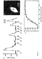
- FIG. 4a presents the temporal evolution of the phase signal measured, in real-time by DHI, in the domain delimited by a black rectangle in Fig. 4b , which presents a typical example of a quantitative phase contrast image of a living mouse cortical neuron immersed in a physiological solution.
- Cells were observed in a control solution (HEPES-buffered physiological solution) and pharmacological agents were applied as short pulses, of 20 seonds duration. These pulses of pharmacological agents are indicated by black triangles in Fig. 4a .
- Marked phase increases occur when glutamate (GLUT) is applied alone, at instants indicated by black triangles 41, 42, 43 and 44.
- the concentrations of GLUT are respectively 15 ⁇ M, 10 ⁇ M, 15 ⁇ M and 20 ⁇ M.
- 400 ⁇ M of kynurenate (KYN) a broad spectrum ionotropic glutamate receptor antagonist, has been added to GLUT. No increase of the phase signal occurs in this case, indicating that the observed effect of GLUT is inhibited by KYN.
- GLUT The effect of GLUT is also inhibited when 5 ⁇ M of MK-801, an NMDA specific receptor antagonist, has been added to GLUT in the physiological solution, at instants indicated by black triangles 47 and 48.
- MK-801 an NMDA specific receptor antagonist
- FIG. 4a the application of glutamate pulses induced reversible OPL or phase increases lasting for several minutes. These OPL increases could be reproduced several times over periods of more than three hours.
- Figure 4a shows also that these glutamate-mediated responses were inhibited by kynurenate, a broad-spectrum ionotropic glutamate receptor antagonist, and by MK-801, a specific NMDA receptor antagonist, thus stressing the receptor specific nature of the effect.
- a concentration-response curve ( Fig.
- glycine is an NMDA receptor co-agonist
- this behavior further emphasizes the role these receptors in the glutamate-evoked responses.
- Figure 4a shows an example of the evolution of the OPL averaged over a specific area of the sample, and gives only a partial idea of the real potential of the method of the present disclosure.
- DHI the spatial distribution of OPL can be defined, with a transverse resolution of for example 0.3 ⁇ m, and OPL time courses, such as presented in Fig. 4a , can be obtained for different micro-domains of the cell, or for each pixel of the quantitative phase-contrast image.
- the recorded signal can therefore be followed over time and space, for example by constructing animated sequences, for example by using the processing unit 18.
- the high sensitivity of the present disclosure has revealed that glutamate applied during a few seconds at physiological concentrations induces reversible morphological changes mediated by NMDA receptors, in microdomains of mouse cortical neurons.
- Morphological neuronal changes (following pharmacological medium applications: Glutamate, MK801..) have been monitored during a few hours.
- the whole holographic microscope may be enclosed in a container.
- different noise sources remain (such as coherent noise), extremely sensitive to opto-mechanical instabilities, which may perturb the reconstructed images.
- These residual noise sources render the quantitative analysis of neuronal morphology changes very difficult.
- a device that generates and delivers a controlled energy in the area of the biological sample. This controlled energy may be mechanical vibrations and may be transmitted by perfusion line to the chamber.
- the method of the present invention uses in priority a DHI technique to measure the phase of a radiation, and in particular the method described in patent WO 00/20929 .
- a DHI technique to measure the phase of a radiation
- the present invention is also related to methods using phase measuring techniques such as in-line digital holography, or Fourier-transform digital holography, or digital heterodyne holography, or phase-shifting interferometric techniques.
Landscapes
- Physics & Mathematics (AREA)
- General Physics & Mathematics (AREA)
- Engineering & Computer Science (AREA)
- Computing Systems (AREA)
- Theoretical Computer Science (AREA)
- Investigating Or Analysing Materials By Optical Means (AREA)
- Holo Graphy (AREA)
- Image Processing (AREA)
Claims (8)
- Verfahren zum Bereitstellen von mindestens einer tomografischen oder ebenen Verteilung (n(x, y)) von Brechungsindexwerten in einer Probe (1), wobei sich die Probe (1) in einer Probeneinheit (4) befindet, die Probeneinheit (4) einen Behälter (2) beinhaltet, der ein dispersives Medium (3), in dem sich die Probe (1) befindet, enthält, wobei das Dispersionsgesetz des Brechungsindex des Mediums (3) bekannt ist, wobei das Verfahren die folgenden Schritte umfasst:- Beleuchten der Probe (1) mit elektromagnetischer Strahlung;- Erzeugen einer Objektwelle (7) in einer Übertragungsabbildungsgeometrie durch Sammeln der elektromagnetischen Strahlung, die die Probe (1) durchquert hat;- Erzeugen einer Referenzwelle (10) aus der elektromagnetischen Strahlung,- Erzeugen mehrerer Hologramme (12) über Interferenz zwischen der Referenzwelle (10) und der Objektwelle (7), wobei die mehreren Hologramme (12) erzeugt werden, indem der Einfallswinkel der elektromagnetischen Strahlung, die die Probe (1) beleuchtet, variiert wird;- Erzeugen mehrerer digitaler Hologramme (14) durch Erfassen und Digitalisieren der mehreren Hologramme (12);- Bereitstellen mehrerer Amplitudenkontrastbilder (16) und/oder mehrerer quantitativer Phasenkontrastbilder (17) durch numerische Rekonstruktionsberechnungen, die an den mehreren digitalen Hologrammen (14) angewendet werden;- Berechnen der mindestens einen tomografischen oder ebenen Verteilung (n(x, y)) von Brechungsindexwerten in der Probe (1) basierend auf dem bekannten Dispersionsgesetz des Brechungsindex des Mediums und auf den mehreren Amplitudenkontrastbildern (16) und/oder den mehreren quantitativen Phasenkontrastbildern (17); undwobei die Wellenlänge der elektromagnetischen Strahlung modifiziert wird und die mehreren Hologramme (12) erzeugt werden, indem die Wellenlänge der elektromagnetischen Strahlung und der Einfallswinkel der elektromagnetischen Strahlung variiert werden.
- Verfahren nach Anspruch 1, das ferner den Schritt des Berechnens mehrerer tomografischer oder ebener Verteilungen (n(x, y)) von Brechungsindexwerten in der Probe (1) basierend auf den mehreren Amplitudenkontrastbildern (16) und/oder den mehreren quantitativen Phasenkontrastbildern (17) und des Erzeugens einer Tomografie der Probe (1) unter Verwendung der mehreren tomografischen oder ebenen Verteilungen (n(x, y)) von Brechungsindexwerten in der Probe (1) beinhaltet.
- Verfahren nach Anspruch 1 oder 2, wobei das Variieren des Einfallswinkels der elektromagnetischen Strahlung, die die Probe (1) beleuchtet, erzielt wird, indem die Probe (1) gedreht wird.
- Verfahren nach Anspruch 1 oder 2, wobei das Variieren des Einfallswinkels der elektromagnetischen Strahlung, die die Probe (1) beleuchtet, erzielt wird, indem ein Strahl der elektromagnetischen Strahlung, die die Probe (1) beleuchtet, verschoben wird.
- Vorrichtung zum Bereitstellen von mindestens einer tomografischen oder ebenen Verteilung (n(x, y)) von Brechungsindexwerten in einer Probe (1), die sich in einer Probeneinheit (4) befindet, die einen Behälter (2) beinhaltet, der dazu ausgelegt ist, ein dispersives Medium (3), in dem die Probe (1) enthalten ist, zu enthalten, wobei das Dispersionsgesetz des Brechungsindex des Mediums (3) bekannt ist, wobei die Vorrichtung Folgendes umfasst:- mindestens eine Quelle (8) elektromagnetischer Strahlung, die dazu ausgelegt ist, die emittierte Wellenlänge zu variieren;- Mittel zum Beleuchten der Probe (1) mit der elektromagnetischen Strahlung;- Mittel zum Erzeugen einer Objektwelle (7) in einer Übertragungsabbildungsgeometrie durch Sammeln der elektromagnetischen Strahlung, die die Probe (1) durchquert hat;- Mittel zum Erzeugen einer Referenzwelle (10) aus der elektromagnetischen Strahlung;- Mittel zum Erzeugen mehrerer Hologramme (12) durch Interferenz zwischen der Referenzwelle (10) und der Objektwelle (7) und durch Variieren des Einfallswinkels der elektromagnetischen Strahlung, die die Probe (1) beleuchtet;- Mittel zum Erzeugen mehrerer digitaler Hologramme (14) durch Erfassen und Digitalisieren der mehreren Hologramme (12);- eine Rekonstruktionseinheit (15), die mehrere Amplitudenkontrastbilder (16) und/oder mehrere quantitative Phasenkontrastbilder (17) durch numerische Berechnungen, die an den mehreren digitalen Hologrammen (12) angewendet werden, bereitstellt; und wobei die Vorrichtung durch Folgendes gekennzeichnet ist:- eine Verarbeitungseinheit (18), die dazu konfiguriert ist, die mindestens eine tomografische oder ebene Verteilung (n(x, y)) von Brechungsindexwerten in der Probe (1) basierend auf dem bekannten Dispersionsgesetz des Brechungsindex des Mediums und auf den mehreren Amplitudenkontrastbildern (16) und/oder den mehreren quantitativen Phasenkontrastbildern (17) zu berechnen, undwobei die Verarbeitungseinheit (18) dazu konfiguriert ist, die mindestens eine tomografische oder ebene Verteilung (n(x, y)) von Brechungsindexwerten in der Probe (1) basierend auf den mehreren Amplitudenkontrastbildern (16) und/oder den mehreren quantitativen Phasenkontrastbildern (17) zu berechnen, die durch Variieren des Einfallswinkels der elektromagnetischen Strahlung, die die Probe beleuchtet, und durch Variieren der Wellenlänge der elektromagnetischen Strahlung erzeugt werden.
- Vorrichtung nach Anspruch 5, wobei die Verarbeitungseinheit (18) dazu konfiguriert ist, mehrere tomografische oder ebene Verteilungen (n(x, y)) von Brechungsindexwerten in der Probe (1) basierend auf den mehreren Amplitudenkontrastbildern (16) und/oder mehreren quantitativen Phasenkontrastbildern (17) zu berechnen, und dazu konfiguriert ist, eine Tomografie der Probe (1) unter Verwendung der mehreren tomografischen oder ebenen Verteilungen (n(x, y)) von Brechungsindexwerten in der Probe (1) zu erzeugen.
- Vorrichtung nach Anspruch 5 oder 6, wobei die Verarbeitungseinheit (18) dazu konfiguriert ist, die mindestens eine tomografische oder ebene Verteilung (n(x, y)) von Brechungsindexwerten in der Probe (1) basierend auf den mehreren Amplitudenkontrastbildern (16) und/oder mehreren quantitativen Phasenkontrastbildern (17), die durch Variieren des Einfallswinkels der elektromagnetischen Strahlung, die die Probe (1) beleuchtet, erzeugt werden, durch eine Drehung der Probe (1) zu berechnen.
- Vorrichtung nach Anspruch 5 oder 6, wobei die Verarbeitungseinheit (18) dazu konfiguriert ist, die mindestens eine tomografische oder ebene Verteilung (n(x, y)) von Brechungsindexwerten in der Probe (1) basierend auf den mehreren Amplitudenkontrastbildern (16) und/oder mehreren quantitativen Phasenkontrastbildern (17), die durch Variieren des Einfallswinkels der elektromagnetischen Strahlung, die die Probe (1) beleuchtet, erzeugt werden, durch Verschieben eines Strahls der elektromagnetischen Strahlung, die die Probe (1) beleuchtet, zu berechnen.
Applications Claiming Priority (3)
| Application Number | Priority Date | Filing Date | Title |
|---|---|---|---|
| CH0100701 | 2001-12-04 | ||
| PCT/CH2002/000660 WO2003048868A1 (en) | 2001-12-04 | 2002-12-04 | Apparatus and method for digital holographic imaging |
| EP02804141.6A EP1451646B1 (de) | 2001-12-04 | 2002-12-04 | Vorrichtung und verfahren zur digitalen holographischen abbildung |
Related Parent Applications (2)
| Application Number | Title | Priority Date | Filing Date |
|---|---|---|---|
| EP02804141.6A Division EP1451646B1 (de) | 2001-12-04 | 2002-12-04 | Vorrichtung und verfahren zur digitalen holographischen abbildung |
| EP02804141.6A Division-Into EP1451646B1 (de) | 2001-12-04 | 2002-12-04 | Vorrichtung und verfahren zur digitalen holographischen abbildung |
Publications (2)
| Publication Number | Publication Date |
|---|---|
| EP3252538A1 EP3252538A1 (de) | 2017-12-06 |
| EP3252538B1 true EP3252538B1 (de) | 2019-02-06 |
Family
ID=4358268
Family Applications (2)
| Application Number | Title | Priority Date | Filing Date |
|---|---|---|---|
| EP17173722.4A Expired - Lifetime EP3252538B1 (de) | 2001-12-04 | 2002-12-04 | Vorrichtung und verfahren zur digitalen holographischen bildgebung |
| EP02804141.6A Expired - Lifetime EP1451646B1 (de) | 2001-12-04 | 2002-12-04 | Vorrichtung und verfahren zur digitalen holographischen abbildung |
Family Applications After (1)
| Application Number | Title | Priority Date | Filing Date |
|---|---|---|---|
| EP02804141.6A Expired - Lifetime EP1451646B1 (de) | 2001-12-04 | 2002-12-04 | Vorrichtung und verfahren zur digitalen holographischen abbildung |
Country Status (5)
| Country | Link |
|---|---|
| US (1) | US6943924B2 (de) |
| EP (2) | EP3252538B1 (de) |
| JP (1) | JP4358631B2 (de) |
| AU (1) | AU2002365676A1 (de) |
| WO (1) | WO2003048868A1 (de) |
Families Citing this family (44)
| Publication number | Priority date | Publication date | Assignee | Title |
|---|---|---|---|---|
| US7448269B2 (en) * | 2003-08-12 | 2008-11-11 | Northwestern University | Scanning near field ultrasound holography |
| US8438927B2 (en) * | 2003-08-12 | 2013-05-14 | Northwestern University | Scanning near field thermoelastic acoustic holography (SNFTAH) |
| US7119905B2 (en) * | 2003-08-26 | 2006-10-10 | Ut-Battelle Llc | Spatial-heterodyne interferometry for transmission (SHIFT) measurements |
| US6999178B2 (en) | 2003-08-26 | 2006-02-14 | Ut-Battelle Llc | Spatial-heterodyne interferometry for reflection and transmission (SHIRT) measurements |
| SE0302676D0 (sv) | 2003-10-09 | 2003-10-09 | Neural Ab | Method and apparatus for holographic refractometry |
| JP4698992B2 (ja) * | 2004-09-14 | 2011-06-08 | 浜松ホトニクス株式会社 | 試料計測装置及び計測方法 |
| EP1952204A4 (de) * | 2005-10-06 | 2011-12-14 | Univ Northwestern | Raster-nahfeld-ultraschall-holografie |
| EP1963927B1 (de) * | 2005-12-22 | 2020-01-15 | Phase Holographic Imaging PHI AB | Verfahren und vorrichtung zur analyse einer probe von zellen |
| EP2492921A1 (de) * | 2007-01-26 | 2012-08-29 | New York University | Holografische Mikroskopie von holografisch gefangenen dreidimensionalen Strukturen |
| US8194124B2 (en) * | 2007-10-09 | 2012-06-05 | Nanyang Technological University | In-line digital holographic microscope and a method of in-line digital holographic microscopy |
| EP3079023B1 (de) | 2007-10-30 | 2019-10-16 | New York University | Verfolgung und kennzeichnung von partikeln über holografische videomikroskopie |
| JP5022274B2 (ja) * | 2008-03-06 | 2012-09-12 | 浜松ホトニクス株式会社 | 観察装置 |
| US7889413B1 (en) * | 2008-06-12 | 2011-02-15 | The Unites States Of America As Represented By The Secretary Of The Air Force | Field generating nanoparticles doped in light valves |
| EP2300880A4 (de) * | 2008-06-19 | 2011-11-23 | Phase Holographic Imaging Phi Ab | Analyse von transparenten biologischen objekten |
| JP5168693B2 (ja) * | 2008-09-30 | 2013-03-21 | 株式会社 エフケー光学研究所 | 試料の高さの計測方法 |
| US9316578B2 (en) | 2008-10-30 | 2016-04-19 | New York University | Automated real-time particle characterization and three-dimensional velocimetry with holographic video microscopy |
| EP2401601B1 (de) | 2009-02-24 | 2021-09-22 | Lyncee Tec S.A. | Überwachung von energie- und partikelströmen mittels elektromagnetischer wellen |
| US7978336B2 (en) * | 2009-03-16 | 2011-07-12 | Ut-Battelle, Llc | Three wavelength quantitative imaging systems |
| US8264694B2 (en) * | 2009-03-16 | 2012-09-11 | Ut-Battelle, Llc | Quantitative phase-contrast and excitation-emission systems |
| US8248614B2 (en) * | 2009-03-16 | 2012-08-21 | Ut-Battelle, Llc | Quantitative phase-imaging systems |
| US20120196316A1 (en) | 2009-06-25 | 2012-08-02 | Phase Holographic Imaging Phi Ab | Analysis of ova or embryos with digital holographic imaging |
| EP2534540B1 (de) * | 2010-02-09 | 2019-05-22 | Phase Holographic Imaging PHI AB | Verfahren für digitale holographische mikroskopie und abbildung auf gekennzeichneten zellproben |
| US9176152B2 (en) | 2010-05-25 | 2015-11-03 | Arryx, Inc | Methods and apparatuses for detection of positional freedom of particles in biological and chemical analyses and applications in immunodiagnostics |
| US8354651B2 (en) | 2010-06-30 | 2013-01-15 | Ut-Battelle, Llc | Positron emission imaging device and method of using the same |
| US9360468B2 (en) * | 2010-08-20 | 2016-06-07 | Lyncee Tec S.A. | Method for monitoring cell viability |
| US9476694B2 (en) * | 2010-11-12 | 2016-10-25 | Universite Libre De Bruxelles | Optical method for characterizing transparent particles |
| WO2013010595A1 (en) * | 2011-07-19 | 2013-01-24 | Ovizio Imaging Systems N.V. | An object database and object database improving method |
| EP2594334A1 (de) | 2011-11-21 | 2013-05-22 | Drive O2 | Probenfläschchen zur digitalen holographischen Analyse einer flüssigen Zellprobe |
| CN108107197B (zh) | 2011-07-19 | 2020-05-08 | 奥维茨奥成像系统公司 | 用于检测和/或分类细胞样品中的癌细胞的方法和系统 |
| WO2013019640A1 (en) * | 2011-07-29 | 2013-02-07 | The Regents Of The University Of California | Lensfree holographic microscopy using wetting films |
| EP2626686A1 (de) | 2012-02-13 | 2013-08-14 | Ovizio Imaging Systems NV/SA | Durchflusszytometer mit digitalem holografischen Mikroskop |
| US9904248B2 (en) | 2012-09-20 | 2018-02-27 | Ovizio Imaging Systems NV/SA | Digital holographic microscope with fluid systems |
| ES2534960B1 (es) | 2013-10-30 | 2016-02-09 | Universitat De València | Microscopio, método y programa de ordenador para la obtención de imágenes cuantitativas de fase por medio de microscopía holográfica digital, y kit para adaptar un microscopio óptico |
| WO2015175046A2 (en) | 2014-02-12 | 2015-11-19 | New York University | Y fast feature identificaiton for holographic tracking and characterization of colloidal particles |
| ES2913524T3 (es) | 2014-11-12 | 2022-06-02 | Univ New York | Huellas coloidales para materiales blandos usando caracterización holográfica total |
| KR102579248B1 (ko) | 2015-09-18 | 2023-09-15 | 뉴욕 유니버시티 | 정밀 슬러리 내 대형 불순물 입자의 홀로그래픽 검출 및 특성화 |
| EP3196631A1 (de) | 2016-01-19 | 2017-07-26 | Ovizio Imaging Systems NV/SA | Digitales holografisches mikroskop mit elektrofluidischem system, besagtes elektrofluidisches system und verfahren zur verwendung |
| WO2017139279A2 (en) | 2016-02-08 | 2017-08-17 | New York University | Holographic characterization of protein aggregates |
| US10670677B2 (en) | 2016-04-22 | 2020-06-02 | New York University | Multi-slice acceleration for magnetic resonance fingerprinting |
| JP6894620B2 (ja) * | 2017-02-09 | 2021-06-30 | 国立大学法人千葉大学 | 物理厚さ推定プログラム及び屈折率データ推定プログラム、並びに、物理厚さデータ推定システム及び屈折率データ推定システム |
| KR102412253B1 (ko) * | 2018-11-30 | 2022-06-24 | 한국전자통신연구원 | 미생물 분석 장치 및 방법 |
| CA3127700A1 (en) * | 2019-02-01 | 2020-08-06 | Universite Laval | System and method for determining a refractive index of a medium |
| US11543338B2 (en) | 2019-10-25 | 2023-01-03 | New York University | Holographic characterization of irregular particles |
| US11948302B2 (en) | 2020-03-09 | 2024-04-02 | New York University | Automated holographic video microscopy assay |
Family Cites Families (7)
| Publication number | Priority date | Publication date | Assignee | Title |
|---|---|---|---|---|
| US4195131A (en) * | 1977-03-09 | 1980-03-25 | Papas Gary R | Environmentally controlled unit |
| WO1998013715A1 (fr) * | 1996-09-27 | 1998-04-02 | Vincent Lauer | Microscope generant une representation tridimensionnelle d'un objet |
| US6262818B1 (en) | 1998-10-07 | 2001-07-17 | Institute Of Applied Optics, Swiss Federal Institute Of Technology | Method for simultaneous amplitude and quantitative phase contrast imaging by numerical reconstruction of digital holograms |
| FR2792082B1 (fr) * | 1999-04-06 | 2003-05-30 | Thomson Csf | Dispositif d'holographie numerique |
| US6022943A (en) | 1999-04-07 | 2000-02-08 | General Electric Company | Optical quality polycarbonates with reduced static charge and method for making same |
| CA2724743C (fr) * | 2001-06-29 | 2014-11-25 | Universite Libre De Bruxelles | Procede et dispositif destines a l'obtention par microscopie d'images en trois dimensions d'un echantillon |
| CN1310045C (zh) * | 2002-10-01 | 2007-04-11 | 古河电气工业株式会社 | 光纤、光传送线路以及光纤的制造方法 |
-
2002
- 2002-12-04 JP JP2003549995A patent/JP4358631B2/ja not_active Expired - Lifetime
- 2002-12-04 WO PCT/CH2002/000660 patent/WO2003048868A1/en active Application Filing
- 2002-12-04 EP EP17173722.4A patent/EP3252538B1/de not_active Expired - Lifetime
- 2002-12-04 EP EP02804141.6A patent/EP1451646B1/de not_active Expired - Lifetime
- 2002-12-04 US US10/497,312 patent/US6943924B2/en not_active Expired - Lifetime
- 2002-12-04 AU AU2002365676A patent/AU2002365676A1/en not_active Abandoned
Non-Patent Citations (1)
| Title |
|---|
| None * |
Also Published As
| Publication number | Publication date |
|---|---|
| WO2003048868A1 (en) | 2003-06-12 |
| EP3252538A1 (de) | 2017-12-06 |
| JP2005512127A (ja) | 2005-04-28 |
| US20050036181A1 (en) | 2005-02-17 |
| EP1451646A1 (de) | 2004-09-01 |
| EP1451646B1 (de) | 2018-09-19 |
| US6943924B2 (en) | 2005-09-13 |
| AU2002365676A1 (en) | 2003-06-17 |
| JP4358631B2 (ja) | 2009-11-04 |
Similar Documents
| Publication | Publication Date | Title |
|---|---|---|
| EP3252538B1 (de) | Vorrichtung und verfahren zur digitalen holographischen bildgebung | |
| US10113961B2 (en) | Apparatus and method for quantitive phase tomography through linear scanning with coherent and non-coherent detection | |
| Kim | Principles and techniques of digital holographic microscopy | |
| JP4772961B2 (ja) | ディジタル・ホログラムを数値的に再構成することにより、振幅コントラスト画像と定量的位相コントラスト画像を同時に形成する方法 | |
| EP2954309B1 (de) | Durchflusszytometrie mit holografischer 3d-bildgebung | |
| Kim | Applications of digital holography in biomedical microscopy | |
| US7127109B1 (en) | Digital interference holographic microscope and methods | |
| US20090128825A1 (en) | Apparatus and method for dynamic cellular probing and diagnostics using holographic optical forcing array | |
| TWI797377B (zh) | 表面形狀量測裝置以及表面形狀量測方法 | |
| Tychinsky et al. | Interference microscopy in cell biophysics. 1. Principles and methodological aspects of coherent phase microscopy | |
| Rybnikov et al. | Using digital off-axis holograms to investigate changes of state of living neuronal cultures | |
| Almoro et al. | Object wave reconstruction by speckle illumination and phase retrieval | |
| US20230324275A1 (en) | A simple in-line digital holography system for measuring 3d cell shape | |
| Creath | Dynamic quantitative phase images of pond life, insect wings, and in vitro cell cultures | |
| Creath | Dynamic phase imaging utilizing a 4-dimensional microscope system | |
| Bergoënd et al. | Diffraction tomography for biological cells imaging using digital holographic microscopy | |
| Lobyntseva et al. | Phase visualization in the study of cellular structures by confocal microscopy | |
| Marquet et al. | Exploring cell structure, dynamics and homeostasis with a multimodal microscopy approach based on digital holographic microscopy: towards identifying early biomarkers of cell viability and cytotoxicity | |
| Shaked et al. | Quantitative phase microscopy of biological cell dynamics by wide-field digital interferometry | |
| Chaumet et al. | Quantitative phase microscopies: accuracy comparison | |
| Lokberg | Speckles and speckle techniques for biomedical applications | |
| Peruhov et al. | Applications of holographic microscopy in life sciences | |
| Pavillon et al. | Optical tomography by digital holographic microscopy | |
| Vertu et al. | Diffraction microtomography with sample rotation: primary result on the influence of a missing apple core in the recorded frequency space | |
| Charrière et al. | Use of digital holographic microscopy in tomography |
Legal Events
| Date | Code | Title | Description |
|---|---|---|---|
| PUAI | Public reference made under article 153(3) epc to a published international application that has entered the european phase |
Free format text: ORIGINAL CODE: 0009012 |
|
| STAA | Information on the status of an ep patent application or granted ep patent |
Free format text: STATUS: THE APPLICATION HAS BEEN PUBLISHED |
|
| AC | Divisional application: reference to earlier application |
Ref document number: 1451646 Country of ref document: EP Kind code of ref document: P |
|
| AK | Designated contracting states |
Kind code of ref document: A1 Designated state(s): AT BE BG CH CY CZ DE DK EE ES FI FR GB GR IE IT LI LU MC NL PT SE SI SK TR |
|
| STAA | Information on the status of an ep patent application or granted ep patent |
Free format text: STATUS: REQUEST FOR EXAMINATION WAS MADE |
|
| 17P | Request for examination filed |
Effective date: 20180528 |
|
| RBV | Designated contracting states (corrected) |
Designated state(s): AT BE BG CH CY CZ DE DK EE ES FI FR GB GR IE IT LI LU MC NL PT SE SI SK TR |
|
| GRAP | Despatch of communication of intention to grant a patent |
Free format text: ORIGINAL CODE: EPIDOSNIGR1 |
|
| STAA | Information on the status of an ep patent application or granted ep patent |
Free format text: STATUS: GRANT OF PATENT IS INTENDED |
|
| INTG | Intention to grant announced |
Effective date: 20180823 |
|
| GRAS | Grant fee paid |
Free format text: ORIGINAL CODE: EPIDOSNIGR3 |
|
| GRAA | (expected) grant |
Free format text: ORIGINAL CODE: 0009210 |
|
| STAA | Information on the status of an ep patent application or granted ep patent |
Free format text: STATUS: THE PATENT HAS BEEN GRANTED |
|
| AC | Divisional application: reference to earlier application |
Ref document number: 1451646 Country of ref document: EP Kind code of ref document: P |
|
| AK | Designated contracting states |
Kind code of ref document: B1 Designated state(s): AT BE BG CH CY CZ DE DK EE ES FI FR GB GR IE IT LI LU MC NL PT SE SI SK TR |
|
| REG | Reference to a national code |
Ref country code: GB Ref legal event code: FG4D |
|
| REG | Reference to a national code |
Ref country code: CH Ref legal event code: EP Ref country code: AT Ref legal event code: REF Ref document number: 1095287 Country of ref document: AT Kind code of ref document: T Effective date: 20190215 |
|
| REG | Reference to a national code |
Ref country code: DE Ref legal event code: R096 Ref document number: 60249783 Country of ref document: DE |
|
| REG | Reference to a national code |
Ref country code: IE Ref legal event code: FG4D |
|
| REG | Reference to a national code |
Ref country code: CH Ref legal event code: NV Representative=s name: ANDRE ROLAND S.A., CH |
|
| REG | Reference to a national code |
Ref country code: SE Ref legal event code: TRGR |
|
| REG | Reference to a national code |
Ref country code: NL Ref legal event code: FP |
|
| PG25 | Lapsed in a contracting state [announced via postgrant information from national office to epo] |
Ref country code: PT Free format text: LAPSE BECAUSE OF FAILURE TO SUBMIT A TRANSLATION OF THE DESCRIPTION OR TO PAY THE FEE WITHIN THE PRESCRIBED TIME-LIMIT Effective date: 20190606 Ref country code: FI Free format text: LAPSE BECAUSE OF FAILURE TO SUBMIT A TRANSLATION OF THE DESCRIPTION OR TO PAY THE FEE WITHIN THE PRESCRIBED TIME-LIMIT Effective date: 20190206 |
|
| REG | Reference to a national code |
Ref country code: AT Ref legal event code: MK05 Ref document number: 1095287 Country of ref document: AT Kind code of ref document: T Effective date: 20190206 |
|
| PG25 | Lapsed in a contracting state [announced via postgrant information from national office to epo] |
Ref country code: BG Free format text: LAPSE BECAUSE OF FAILURE TO SUBMIT A TRANSLATION OF THE DESCRIPTION OR TO PAY THE FEE WITHIN THE PRESCRIBED TIME-LIMIT Effective date: 20190506 Ref country code: GR Free format text: LAPSE BECAUSE OF FAILURE TO SUBMIT A TRANSLATION OF THE DESCRIPTION OR TO PAY THE FEE WITHIN THE PRESCRIBED TIME-LIMIT Effective date: 20190507 |
|
| PG25 | Lapsed in a contracting state [announced via postgrant information from national office to epo] |
Ref country code: IT Free format text: LAPSE BECAUSE OF FAILURE TO SUBMIT A TRANSLATION OF THE DESCRIPTION OR TO PAY THE FEE WITHIN THE PRESCRIBED TIME-LIMIT Effective date: 20190206 Ref country code: CZ Free format text: LAPSE BECAUSE OF FAILURE TO SUBMIT A TRANSLATION OF THE DESCRIPTION OR TO PAY THE FEE WITHIN THE PRESCRIBED TIME-LIMIT Effective date: 20190206 Ref country code: SK Free format text: LAPSE BECAUSE OF FAILURE TO SUBMIT A TRANSLATION OF THE DESCRIPTION OR TO PAY THE FEE WITHIN THE PRESCRIBED TIME-LIMIT Effective date: 20190206 Ref country code: ES Free format text: LAPSE BECAUSE OF FAILURE TO SUBMIT A TRANSLATION OF THE DESCRIPTION OR TO PAY THE FEE WITHIN THE PRESCRIBED TIME-LIMIT Effective date: 20190206 Ref country code: EE Free format text: LAPSE BECAUSE OF FAILURE TO SUBMIT A TRANSLATION OF THE DESCRIPTION OR TO PAY THE FEE WITHIN THE PRESCRIBED TIME-LIMIT Effective date: 20190206 Ref country code: DK Free format text: LAPSE BECAUSE OF FAILURE TO SUBMIT A TRANSLATION OF THE DESCRIPTION OR TO PAY THE FEE WITHIN THE PRESCRIBED TIME-LIMIT Effective date: 20190206 |
|
| REG | Reference to a national code |
Ref country code: DE Ref legal event code: R097 Ref document number: 60249783 Country of ref document: DE |
|
| PLBE | No opposition filed within time limit |
Free format text: ORIGINAL CODE: 0009261 |
|
| STAA | Information on the status of an ep patent application or granted ep patent |
Free format text: STATUS: NO OPPOSITION FILED WITHIN TIME LIMIT |
|
| PG25 | Lapsed in a contracting state [announced via postgrant information from national office to epo] |
Ref country code: AT Free format text: LAPSE BECAUSE OF FAILURE TO SUBMIT A TRANSLATION OF THE DESCRIPTION OR TO PAY THE FEE WITHIN THE PRESCRIBED TIME-LIMIT Effective date: 20190206 |
|
| 26N | No opposition filed |
Effective date: 20191107 |
|
| PG25 | Lapsed in a contracting state [announced via postgrant information from national office to epo] |
Ref country code: SI Free format text: LAPSE BECAUSE OF FAILURE TO SUBMIT A TRANSLATION OF THE DESCRIPTION OR TO PAY THE FEE WITHIN THE PRESCRIBED TIME-LIMIT Effective date: 20190206 |
|
| PG25 | Lapsed in a contracting state [announced via postgrant information from national office to epo] |
Ref country code: TR Free format text: LAPSE BECAUSE OF FAILURE TO SUBMIT A TRANSLATION OF THE DESCRIPTION OR TO PAY THE FEE WITHIN THE PRESCRIBED TIME-LIMIT Effective date: 20190206 |
|
| PG25 | Lapsed in a contracting state [announced via postgrant information from national office to epo] |
Ref country code: MC Free format text: LAPSE BECAUSE OF FAILURE TO SUBMIT A TRANSLATION OF THE DESCRIPTION OR TO PAY THE FEE WITHIN THE PRESCRIBED TIME-LIMIT Effective date: 20190206 |
|
| PG25 | Lapsed in a contracting state [announced via postgrant information from national office to epo] |
Ref country code: IE Free format text: LAPSE BECAUSE OF NON-PAYMENT OF DUE FEES Effective date: 20191204 Ref country code: LU Free format text: LAPSE BECAUSE OF NON-PAYMENT OF DUE FEES Effective date: 20191204 |
|
| PG25 | Lapsed in a contracting state [announced via postgrant information from national office to epo] |
Ref country code: CY Free format text: LAPSE BECAUSE OF FAILURE TO SUBMIT A TRANSLATION OF THE DESCRIPTION OR TO PAY THE FEE WITHIN THE PRESCRIBED TIME-LIMIT Effective date: 20190206 |
|
| PGFP | Annual fee paid to national office [announced via postgrant information from national office to epo] |
Ref country code: DE Payment date: 20211210 Year of fee payment: 20 Ref country code: GB Payment date: 20211222 Year of fee payment: 20 Ref country code: FR Payment date: 20211224 Year of fee payment: 20 Ref country code: SE Payment date: 20211221 Year of fee payment: 20 |
|
| PGFP | Annual fee paid to national office [announced via postgrant information from national office to epo] |
Ref country code: CH Payment date: 20211221 Year of fee payment: 20 Ref country code: BE Payment date: 20211221 Year of fee payment: 20 |
|
| PGFP | Annual fee paid to national office [announced via postgrant information from national office to epo] |
Ref country code: NL Payment date: 20211221 Year of fee payment: 20 |
|
| REG | Reference to a national code |
Ref country code: DE Ref legal event code: R071 Ref document number: 60249783 Country of ref document: DE |
|
| REG | Reference to a national code |
Ref country code: NL Ref legal event code: MK Effective date: 20221203 |
|
| REG | Reference to a national code |
Ref country code: CH Ref legal event code: PL |
|
| REG | Reference to a national code |
Ref country code: GB Ref legal event code: PE20 Expiry date: 20221203 |
|
| REG | Reference to a national code |
Ref country code: BE Ref legal event code: MK Effective date: 20221204 |
|
| PG25 | Lapsed in a contracting state [announced via postgrant information from national office to epo] |
Ref country code: GB Free format text: LAPSE BECAUSE OF EXPIRATION OF PROTECTION Effective date: 20221203 |
|
| REG | Reference to a national code |
Ref country code: SE Ref legal event code: EUG |