EP3252227A1 - Dampfaufbereitungseinrichtung für ein bügeleisen und bügeleisen - Google Patents
Dampfaufbereitungseinrichtung für ein bügeleisen und bügeleisen Download PDFInfo
- Publication number
- EP3252227A1 EP3252227A1 EP17170840.7A EP17170840A EP3252227A1 EP 3252227 A1 EP3252227 A1 EP 3252227A1 EP 17170840 A EP17170840 A EP 17170840A EP 3252227 A1 EP3252227 A1 EP 3252227A1
- Authority
- EP
- European Patent Office
- Prior art keywords
- steam
- channel
- treatment device
- section
- turns
- Prior art date
- Legal status (The legal status is an assumption and is not a legal conclusion. Google has not performed a legal analysis and makes no representation as to the accuracy of the status listed.)
- Granted
Links
Images


Classifications
-
- D—TEXTILES; PAPER
- D06—TREATMENT OF TEXTILES OR THE LIKE; LAUNDERING; FLEXIBLE MATERIALS NOT OTHERWISE PROVIDED FOR
- D06F—LAUNDERING, DRYING, IRONING, PRESSING OR FOLDING TEXTILE ARTICLES
- D06F75/00—Hand irons
- D06F75/08—Hand irons internally heated by electricity
- D06F75/10—Hand irons internally heated by electricity with means for supplying steam to the article being ironed
- D06F75/14—Hand irons internally heated by electricity with means for supplying steam to the article being ironed the steam being produced from water in a reservoir carried by the iron
-
- D—TEXTILES; PAPER
- D06—TREATMENT OF TEXTILES OR THE LIKE; LAUNDERING; FLEXIBLE MATERIALS NOT OTHERWISE PROVIDED FOR
- D06F—LAUNDERING, DRYING, IRONING, PRESSING OR FOLDING TEXTILE ARTICLES
- D06F75/00—Hand irons
- D06F75/08—Hand irons internally heated by electricity
- D06F75/10—Hand irons internally heated by electricity with means for supplying steam to the article being ironed
- D06F75/20—Arrangements for discharging the steam to the article being ironed
Definitions
- the invention relates to a steam treatment device for an iron and an iron.
- the DE 3402868 C2 describes an iron in which rods are inserted with offset cams in longitudinal bores, so that cavities are formed, which form a labyrinth-like steam channel. In the bars themselves turn a radiator is inserted.
- the invention has as its object to provide an improved steam treatment device for an iron and an improved iron.
- the invention offers the advantage that an unfavorable temperature distribution in a soleplate due to large variations in the material cross section along a heat transport path can be avoided by an at least partially meandering steam channel with a substantially constant channel cross section. Further, by means of such a steam treatment device meander, a steam passage can be lengthened, so that a heat exchange coefficient is increased. Due to the constant cross section of the steam channel and the absence of significant jumps in geometry, as well as abrupt, or sharp changes of direction over an entire steam route, condensation processes in the steam channel can be avoided. Furthermore, the flow resistance through the steam channel and the soleplate can be reduced. Another advantage consists in the improvement of the thermal connection of a lid of the steam treatment device by concept-specific enabled large-area edition, which also condensation can be avoided.
- a steam treatment device may be understood to mean a component for generating or passing steam, in particular steam, through the iron.
- the steam treatment device can be integrated into a superordinate structure in the form of a soleplate.
- the steam outlet can be realized as part of the soleplate.
- the steam channel may be designed, for example meandering. By a deflection angle may be understood an angle about which the steam channel is bent to form a turn.
- the first channel section may face the steam inlet and the second channel section may face the steam outlet.
- the first channel section may have more turns than the second channel section.
- the windings in the first channel section may have a larger deflection angle than the windings in the second channel section.
- the steam channel can have a cross section that is constant within a tolerance range.
- an overall cross section of the steam outlet within the tolerance range can be equal to the cross section of the steam channel.
- a tolerance range can be understood as a deviation of 5, 10 or 20 percent from a cross-sectional reference value.
- a cross section of the first channel section within the tolerance range may be equal to a cross section of the second channel section.
- the first channel section is at least partially surrounded by the second channel section.
- the steam channel can be made as long as possible.
- the steam treatment device may comprise a soleplate.
- the steam outlet can through at least one outlet opening in the Be formed soleplate.
- Under a soleplate can be understood a thermally conductive bottom of the steam treatment device.
- a cross section of the outlet opening within the tolerance range can be equal to the cross section of the steam channel.
- the steam outlet may comprise at least two such outlet openings, wherein an overall cross section of the at least two outlet openings within the tolerance range may be equal to the cross section of the steam channel.
- the outlet opening may be designed diffuser-shaped. As a result, an effectiveness of a steam action in the textile piece can be increased.
- the steam treatment device can be realized with a heating device for heating the steam treatment device.
- a temperature of the steam processing device can be controlled.
- the heater may be configured to heat the steam channel.
- the heating device may be designed to heat the soleplate.
- the heating device extends at least in sections between the first channel section and the second channel section.
- the heater or the steam duct or both at least partially be arranged or be arranged on or in the soleplate to allow thermal coupling between soleplate and heater or between soleplate and steam channel or between the heater and steam channel.
- the heating device and the steam channel can be arranged on a plane on or in the soleplate.
- the steam channel may be substantially mirror-symmetrical relative to a longitudinal axis of the steam processing device. This allows a uniform temperature of the soleplate through the steam channel.
- FIG. 1 shows a schematic representation of a steam treatment device 100 according to an embodiment. Shown is an ironing steam treatment device 100 with a meandering steam channel 102, which connects a steam inlet 104 for introducing steam into the steam treatment device 100 with a steam outlet 106 for discharging steam from the steam treatment device 100, also called the steam outlet region.
- the steam channel 102 has a cross section that is constant from the steam inlet 104 to the steam outlet 106 within a tolerance range.
- the steam treatment device 100 comprises a soleplate 108 with a plurality of outlet openings 110, also called steam holes, which form the steam outlet 106.
- the outlet openings 110 are arranged in the region of a tip of the soleplate 108.
- the outlet openings 110 can also be arranged in other areas of the soleplate 108. In this case, an overall cross section of the outlet openings 110 within the tolerance range is equal to the cross section of the steam channel 102.
- the steam processing device 100 is realized with a heating device 112, which is designed to heat the steam channel 102 and the soleplate 108.
- the steam channel 102 is subdivided into a first channel section 114, also referred to as inflow area, and a second channel section 116, also called outflow area.
- the two channel sections 114, 116 each have, at least in sections, a plurality of turns 118, through which the meandering course of the steam channel 102 results.
- the first channel section 114 faces the steam inlet 104 and the second channel section 116 faces the steam outlet 106.
- the two channel sections 114, 116 differ from each other in that the first channel section 114 has a greater number of turns 118 than the second channel section 116.
- the windings 118 in the first channel section 114 have a larger deflection angle than the turns 118 in the second channel section 116. Exemplary are in FIG. 1 the turns 118 in the first channel section 114 are deflected substantially 180 degrees, while the turns 118 in the second channel section 116 are deflected substantially by 90 degrees.
- the heater 112 here a U-shaped radiator, largely between the two channel sections 114, 116.
- both the heater 112 and the first channel portion 114 in sections surrounded by the second channel portion 116.
- the heater 112 is in contact with each of the two channel sections 114, 116.
- the heater 112 is thermally coupled to the two channel sections 114, 116.
- the steam channel 102 and the heater 112 are arranged according to an embodiment on or in the sole plate 108 and thermally coupled thereto.
- the steam treatment device 100 has according to the in FIG. 1 shown embodiment to a longitudinal axis 120 of the steam treatment device 100 is substantially mirror-symmetrical structure.
- condensate droplets entrained by a vapor stream may escape from the steam holes, which may also be referred to as ironing spitting.
- a textile to be ironed is inadvertently moistened and possibly soiled by the foreign particles contained in the condensate.
- the ironing spit may be caused by a poor re-evaporation process in the ironing steam processing equipment, by condensation processes due to unfavorable cross-sectional changes in the steam duct or by temperature differences, and may occur in all known types of steam iron designs.
- Condensation processes can be caused along the vapor path by abrupt cross-sectional changes, in which due to local pressure fluctuations can lead to undesirable phase transitions.
- a defective re-evaporation process in the steam treatment device can have two main procedural causes. Either the surface is too cold, which deprives the steam of heat, or the steam is not heated sufficiently, or the surface is too warm. Too cold surfaces result from an unfavorable thermal connection of the heating element to the contact surfaces of the steam channel, on the one hand by long distances and on the other hand by low effective Material cross-sections that limit the possible heat transfer.
- the embodiment according to the invention therefore shows a possibility of thermally coupling the steam duct to the heating element over short distances and sufficiently large cross sections.
- a respective cross section of the two channel sections 114, 116 and the total cross section of the outlet openings 110 correspond to that of the steam channel 102. Due to the constant cross section and relatively gentle, curve-like transitions in the flow channel condensation processes and thus the probability of ironing spit are minimized.
- the outlet openings 110 can be diffuser-shaped, so that the steam flow in the steam outlet region is delayed and as a result the kinetic energy of the steam decreases. Thus, the steam is not shot through the fabric, but can act more effectively in the textile.
- the steam channel course is optimized with respect to the three criteria space utilization, mass of a body and maximum influence zone of a heat source.
- the basic body should be as light as possible and have good thermal conductivity in order to allow short heating times.
- the base body may be made of aluminum, for example. Due to the meander-shaped steam channel 102 remain inside relatively comparatively wide ribs, which project from the heater 112 from far into the middle of the sole plate 108. Thus, both the steam channel 102 and the sole plate 108 are thermally optimally connected to the heater 112.
- the heating device 112 can be integrated in the soleplate 108, for example cast in it.
- the steam channel 102 and the heater 112 are ideally located on one level. In this case, a crossing of the heating device 112 through the steam channel 102 can be dispensed with.
- FIG. 2 shows a schematic representation of a cross section through a sole plate 108 FIG. 1 along an in FIG. 1 shown section axis AA, which corresponds to the longitudinal axis of the steam treatment device.
- a steam course through the soleplate 108 is indicated by arrows. Shown are the steam outlet 106 with the outlet openings 110 and the heater 112, which extends through the sole plate 108.
- the outlet openings 110 are designed in a diffuser shape.
- FIG. 3 shows an enlarged view of a portion of a sole plate 108 from FIG. 2 , Shown is an enlargement of the steam outlet 106.
- the outlet openings 110 realized in each case as a diffuser can be seen.
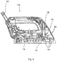
- FIG. 4 shows a schematic representation of an iron 400 according to an embodiment. Shown is a sectional view through the iron 400 without steam hose.
- the iron 400 includes the steam processing device 100, such as a steam treatment device, as described above with reference to FIGS. 1 to 3 is described.
- an external steam inlet 402 of the iron 400 the steam inlet 104 of the steam treatment device 100, the sole plate 108, a cover 404 of the steam treatment device 100 arranged opposite the sole plate 108, a hose nozzle 406 opening into the steam treatment device 100 and the outlet openings 110.
- the steam is passed via flexible, temperature-resistant hoses from a steam boiler to the iron 400, where the steam is first passed through the integrated steam treatment device 100 and exits at the end through the outlet openings 110 on a soleplate outside.
- the hose stub 406 in the cover 404 forms an interface between hose and steam treatment device 100.
- the steam profile is designed so that the largest possible contact surface between the radiator and steam is formed or a long contact time is ensured during the flow of steam.
- effective reheat can be achieved to minimize condensation processes prior to or during the exit of the steam from the iron 400.
- the soleplate 108 is designed, for example, as an aluminum die-cast body with a cast-in heating device and closed with the cover 404.
Landscapes
- Engineering & Computer Science (AREA)
- Textile Engineering (AREA)
- Irons (AREA)
Abstract
Description
- Die Erfindung betrifft eine Dampfaufbereitungseinrichtung für ein Bügeleisen und ein Bügeleisen.
- Die
DE 3402868 C2 beschreibt ein Bügeleisen, bei dem in Längsbohrungen Stäbe mit versetzten Nocken eingeschoben sind, sodass Hohlräume entstehen, die einen labyrinthartigen Dampfkanal bilden. In den Stäben selbst ist wiederum ein Heizkörper eingeschoben. - Der Erfindung stellt sich die Aufgabe, eine verbesserte Dampfaufbereitungseinrichtung für ein Bügeleisen und ein verbessertes Bügeleisen zu schaffen.
- Erfindungsgemäß wird diese Aufgabe durch eine Dampfaufbereitungseinrichtung und ein Bügeleisen mit den Merkmalen der Hauptansprüche gelöst. Vorteilhafte Ausgestaltungen und Weiterbildungen der Erfindung ergeben sich aus den nachfolgenden Unteransprüchen.
- Die Erfindung bietet den Vorteil, dass durch einen zumindest abschnittsweise mäanderförmigen Dampfkanal mit im Wesentlichen konstantem Kanalquerschnitt eine ungünstige Temperaturverteilung in einer Bügelsohle durch starke Schwankungen im Materialquerschnitt entlang eines Wärmetransportwegs vermieden werden kann. Ferner kann mithilfe eines solchen Dampfaufbereitungseinrichtung-Mäanders eine Dampfkanalstrecke verlängert werden, sodass ein Wärmetauscherkoeffizient erhöht wird. Durch den gleichbleibenden Querschnitt des Dampfkanals und den Verzicht auf signifikante Geometriesprünge, sowie abrupte, bzw. scharfe Richtungswechsel über eine gesamte Dampfstrecke können Kondensationsprozesse im Dampfkanal vermieden werden. Des Weiteren kann der Strömungswiderstand durch den Dampfkanal und die Bügelsohle verringert werden. Ein weiterer Vorteil besteht in der Verbesserung der thermischen Anbindung eines Deckels der Dampfaufbereitungseinrichtung durch konzeptspezifisch ermöglichte großflächige Auflage, wodurch ebenfalls Kondensation vermieden werden kann.
- Es wird eine Dampfaufbereitungseinrichtung für ein Bügeleisen vorgestellt, wobei die Dampfaufbereitungseinrichtung folgende Merkmale aufweist:
- einen Dampfeintritt zum Einleiten von Dampf in die Dampfaufbereitungseinrichtung;
- einen Dampfaustritt zum Ausleiten von Dampf aus der Dampfaufbereitungseinrichtung; und
- einen den Dampfeintritt und den Dampfaustritt fluidisch miteinander verbindenden Dampfkanal, wobei der Dampfkanal einen ersten Kanalabschnitt mit einer Mehrzahl von Windungen und einen zweiten Kanalabschnitt mit einer Mehrzahl von Windungen aufweist, wobei sich die Windungen im ersten Kanalabschnitt und die Windungen im zweiten Kanalabschnitt in einem Umlenkungswinkel und/oder einer Anzahl voneinander unterscheiden können.
- Unter einer Dampfaufbereitungseinrichtung kann eine Komponente zum Erzeugen oder Leiten von Dampf, insbesondere von Wasserdampf, durch das Bügeleisen verstanden werden. Die Dampfaufbereitungseinrichtung kann in eine übergeordnete Struktur in Form einer Bügelsohle integriert sein. Hierbei kann der Dampfaustritt als Teil der Bügelsohle realisiert sein. Der Dampfkanal kann beispielsweise mäanderförmig ausgestaltet sein. Unter einem Umlenkungswinkel kann ein Winkel verstanden werden, um den der Dampfkanal umgebogen ist, um eine Windung zu bilden.
- Gemäß einer Ausführungsform kann der erste Kanalabschnitt dem Dampfeintritt und der zweite Kanalabschnitt dem Dampfaustritt zugewandt sein. Hierbei kann der erste Kanalabschnitt mehr Windungen als der zweite Kanalabschnitt aufweisen. Zusätzlich oder alternativ können die Windungen im ersten Kanalabschnitt einen größeren Umlenkungswinkel als die Windungen im zweiten Kanalabschnitt aufweisen. Durch diese Ausführungsform können eine verlustarme Dampfführung und eine effektive Nacherhitzung des Dampfes im Bügeleisen sichergestellt werden.
- Gemäß einer weiteren Ausführungsform kann der Dampfkanal einen innerhalb eines Toleranzbereichs konstanten Querschnitt aufweisen. Insbesondere kann hierbei ein Gesamtquerschnitt des Dampfaustritts innerhalb des Toleranzbereichs gleich dem Querschnitt des Dampfkanals sein. Unter einem Toleranzbereich kann beispielsweise eine Abweichung von 5, 10 oder 20 Prozent von einem Querschnittsreferenzwert verstanden werden. Hierbei kann ein Querschnitt des ersten Kanalabschnitts innerhalb des Toleranzbereichs gleich einem Querschnitt des zweiten Kanalabschnitts sein. Durch diese Ausführungsform kann der Dampfkanal mit relativ sanften, kurvenstetigen Übergängen realisiert werden, wodurch Kondensationsprozesse und somit auch die Wahrscheinlichkeit von Bügeleisenspucken minimiert werden können.
- Es ist vorteilhaft, wenn der erste Kanalabschnitt zumindest teilweise von dem zweiten Kanalabschnitt umgeben ist. Dadurch kann der Dampfkanal möglichst lang ausgeführt werden.
- Gemäß einer weiteren Ausführungsform kann die Dampfaufbereitungseinrichtung eine Bügelsohle umfassen. Der Dampfaustritt kann durch zumindest eine Austrittsöffnung in der Bügelsohle gebildet sein. Unter einer Bügelsohle kann ein thermisch leitfähiger Boden der Dampfaufbereitungseinrichtung verstanden werden. Hierbei kann ein Querschnitt der Austrittsöffnung innerhalb des Toleranzbereichs gleich dem Querschnitt des Dampfkanals sein. Beispielsweise kann der Dampfaustritt zumindest zwei solcher Austrittsöffnungen umfassen, wobei ein Gesamtquerschnitt der zumindest zwei Austrittsöffnungen innerhalb des Toleranzbereichs gleich dem Querschnitt des Dampfkanals sein kann. Diese Ausführungsform ermöglicht eine gleichmäßige Verteilung des Dampfes auf einem zu bügelnden Textilstück.
- Die Austrittsöffnung kann diffusorförmig ausgestaltet sein. Dadurch kann eine Effektivität einer Dampfeinwirkung in das Textilstück erhöht werden.
- Des Weiteren kann die Dampfaufbereitungseinrichtung mit einer Heizeinrichtung zum Heizen der Dampfaufbereitungseinrichtung realisiert sein. Dadurch kann eine Temperatur der Dampfaufbereitungseinrichtung gesteuert werden. Beispielsweise kann die Heizeinrichtung ausgebildet sein, um den Dampfkanal zu heizen. Zusätzlich oder alternativ kann die Heizeinrichtung ausgebildet sein, um die Bügelsohle zu heizen.
- Es ist von Vorteil, wenn die Heizeinrichtung zumindest abschnittsweise zwischen dem ersten Kanalabschnitt und dem zweiten Kanalabschnitt verläuft. Beispielsweise kann hierbei die Heizeinrichtung oder der Dampfkanal oder beides zumindest teilweise an oder in der Bügelsohle angeordnet oder anordenbar sein, um eine thermische Kopplung zwischen Bügelsohle und Heizeinrichtung oder zwischen Bügelsohle und Dampfkanal oder zwischen Heizeinrichtung und Dampfkanal zu ermöglichen. Beispielsweise können die Heizeinrichtung und der Dampfkanal auf einer Ebene an oder in der Bügelsohle angeordnet sein. Durch diese Ausführungsform kann eine Aufheizzeit des Bügeleisens verkürzt werden. Ferner kann dadurch eine gute Regeldynamik und eine gleichmäßige Temperaturverteilung über der Bügelsohle erreicht werden. Ferner kann dadurch eine Gesamthöhe einer Einheit aus Bügelsohle und Dampfaufbereitungseinrichtung verringert werden und somit ein Wärmeeintrag in andere Komponenten des Bügeleisens wie etwa Gehäuse, berührbare Oberflächen wie Griff und Tasten oder Elektronikkomponenten minimiert werden.
- Des Weiteren kann der Dampfkanal relativ zu einer Längsachse der Dampfaufbereitungseinrichtung im Wesentlichen spiegelsymmetrisch verlaufen. Dadurch wird eine gleichmäßige Temperierung der Bügelsohle durch den Dampfkanal ermöglicht.
- Schließlich schafft der hier vorgestellte Ansatz ein Bügeleisen mit einer Dampfaufbereitungseinrichtung gemäß einer der vorstehenden Ausführungsformen.
- Ein Ausführungsbeispiel der Erfindung ist in den Zeichnungen rein schematisch dargestellt und wird nachfolgend näher beschrieben. Es zeigt
- Figur 1
- eine schematische Darstellung einer Dampfaufbereitungseinrichtung gemäß einem Ausführungsbeispiel;
- Figur 2
- eine schematische Darstellung eines Querschnitts durch eine Bügelsohle aus
Figur 1 ; - Figur 3
- eine vergrößerte Darstellung eines Abschnitts einer Bügelsohle aus
Figur 2 ; und - Figur 4
- eine schematische Darstellung eines Bügeleisens gemäß einem Ausführungsbeispiel.
-
Figur 1 zeigt eine schematische Darstellung einer Dampfaufbereitungseinrichtung 100 gemäß einem Ausführungsbeispiel. Gezeigt ist eine Bügeleisendampfaufbereitungseinrichtung 100 mit einem mäanderförmigen Dampfkanal 102, der einen Dampfeintritt 104 zum Einleiten von Dampf in die Dampfaufbereitungseinrichtung 100 mit einem Dampfaustritt 106 zum Ausleiten von Dampf aus der Dampfaufbereitungseinrichtung 100, auch Dampfaustrittsbereich genannt, fluidisch verbindet. Der Dampfkanal 102 weist einen Querschnitt auf, der vom Dampfeintritt 104 bis zum Dampfaustritt 106 innerhalb eines Toleranzbereichs konstant ist. - Die Dampfaufbereitungseinrichtung 100 umfasst gemäß diesem Ausführungsbeispiel eine Bügelsohle 108 mit einer Mehrzahl von Austrittsöffnungen 110, auch Dampflöcher genannt, die den Dampfaustritt 106 bilden. Die Austrittsöffnungen 110 sind im Bereich einer Spitze der Bügelsohle 108 angeordnet. Alternativ können die Austrittsöffnungen 110 auch in anderen Bereichen der Bügelsohle 108 angeordnet sein. Hierbei ist ein Gesamtquerschnitt der Austrittsöffnungen 110 innerhalb des Toleranzbereichs gleich dem Querschnitt des Dampfkanals 102.
- Optional ist die Dampfaufbereitungseinrichtung 100 mit einer Heizeinrichtung 112 realisiert, die ausgebildet ist, um den Dampfkanal 102 sowie die Bügelsohle 108 zu heizen.
- Der Dampfkanal 102 ist in einen ersten Kanalabschnitt 114, auch Einströmbereich genannt, und einen zweiten Kanalabschnitt 116, auch Ausströmbereich genannt, unterteilt. Die beiden Kanalabschnitte 114, 116 weisen jeweils zumindest abschnittsweise eine Mehrzahl von Windungen 118 auf, durch die sich der mäanderförmige Verlauf des Dampfkanals 102 ergibt. Gemäß diesem Ausführungsbeispiel ist der erste Kanalabschnitt 114 dem Dampfeintritt 104 und der zweite Kanalabschnitt 116 dem Dampfaustritt 106 zugewandt. Die beiden Kanalabschnitte 114, 116 unterscheiden sich darin voneinander, dass der erste Kanalabschnitt 114 eine größere Anzahl von Windungen 118 als der zweite Kanalabschnitt 116 aufweist. Ein weiterer Unterschied zwischen den beiden Kanalabschnitten 114, 116 besteht darin, dass die Windungen 118 im ersten Kanalabschnitt 114 einen größeren Umlenkungswinkel als die Windungen 118 im zweiten Kanalabschnitt 116 aufweisen. Beispielhaft sind in
Figur 1 die Windungen 118 im ersten Kanalabschnitt 114 im Wesentlichen um 180 Grad umgelenkt, während die Windungen 118 im zweiten Kanalabschnitt 116 im Wesentlichen um 90 Grad umgelenkt sind. - Wie in
Figur 1 zu erkennen, erstreckt sich die Heizeinrichtung 112, hier ein u-förmiger Heizkörper, größtenteils zwischen den beiden Kanalabschnitten 114, 116. Hierbei sind sowohl die Heizeinrichtung 112 als auch der erste Kanalabschnitt 114 abschnittsweise von dem zweiten Kanalabschnitt 116 umgeben. Die Heizeinrichtung 112 hat mit jedem der beiden Kanalabschnitte 114, 116 Kontakt. Somit ist die Heizeinrichtung 112 mit den beiden Kanalabschnitten 114, 116 thermisch gekoppelt. - Der Dampfkanal 102 und die Heizeinrichtung 112 sind gemäß einem Ausführungsbeispiel an oder in der Bügelsohle 108 angeordnet und mit dieser thermisch gekoppelt.
- Die Dampfaufbereitungseinrichtung 100 weist gemäß dem in
Figur 1 gezeigten Ausführungsbeispiel einen zu einer Längsachse 120 der Dampfaufbereitungseinrichtung 100 im Wesentlichen spiegelsymmetrischen Aufbau auf. - Während des Betriebs eines Bügeleisens können durch einen Dampfstrom mitgerissene Kondensattropfen aus den Dampflöchern austreten, was auch als Bügeleisenspucken bezeichnet werden kann. Dadurch wird ein zu bügelndes Textil ungewollt befeuchtet und gegebenenfalls von den im Kondensat enthaltenen Fremdpartikeln beschmutzt. Das Bügeleisenspucken kann durch einen mangelhaften Nachverdampfungsprozess in der Bügeleisendampfaufbereitungseinrichtung, durch Kondensationsprozesse aufgrund ungünstiger Querschnittsänderungen im Dampfkanal oder durch Temperaturdifferenzen verursacht sein und kann in allen bekannten Konstruktionsvarianten von Dampfbügeleisen auftreten.
- Kondensationsprozesse können entlang des Dampfweges durch abrupte Querschnittsänderungen verursacht sein, in denen aufgrund von lokalen Druckschwankungen zu unerwünschten Phasenübergängen kommen kann.
- Ein mangelhafter Nachverdampfungsprozess in der -Dampfaufbereitungseinrichtung kann hauptsächlich zwei verfahrenstechnische Ursachen haben. Entweder ist die Oberfläche zu kalt, wodurch dem Dampf Wärme entzogen wird oder der Dampf nicht ausreichend erwärmt wird, oder die Oberfläche ist zu warm. Zu kalte Oberflächen ergeben sich durch eine ungünstige thermische Anbindung des Heizelements an die Kontaktflächen des Dampfkanals, einerseits durch große Entfernungen und andererseits durch geringe wirksame Materialquerschnitte, die den möglichen Wärmetransport einschränken. Die erfindungsgemäße Ausführung zeigt daher eine Möglichkeit, den Dampfkanal über kurze Strecken und ausreichend große Querschnitte thermisch an das Heizelement anzukoppeln. Zu heiße Oberflächen können vorliegen, wenn sich beispielsweise in einer Dampfzuleitung zum Bügeleisen kondensiertes Wasser aus einer früheren Nutzung des Dampfbügeleisens befindet, das annähernd Raumtemperatur hat und führen zum sogenannten Leidenfrost-Effekt. Hierbei wird der Wassertropfen durch eine Dampfschicht von der Wärmequelle isoliert, wodurch der Verdampfungsprozess stark verlangsamt wird. In bekannten Dampfbügeleisen wird durch vertikale Trennwände im unteren und/oder oberen Kanalbereich versucht, diese Wassertropfen aufgrund ihrer Trägheit oder Gewichtskraft aufzuhalten. Dies ist aufgrund der hohen kinetischen Energie eines eingetragenen Dampfstoßes bei einem Bügeleisen mit (externer Druck-)Dampferzeugung nicht hinreichend, was dazu führt, dass die Wassertropfen dennoch mitgerissen werden. Zudem führen die zwangsläufig eingebrachten Querschnittssprünge an den Rippen zu den bereits genannten Nachteilen. Dieses Fehlerbild wird jedoch durch die erfindungsgemäße Ausgestaltung des mäanderförmigen Dampfkanals abgefangen. Durch ihre Massenträgheit werden größere Wassertropfen beim Durchqueren des Dampfkanals stets an die kurvenäußere Wandung geschleudert, Dadurch nehmen diese Tropfen den längst möglichen Pfad durch den Dampfkanal und haben besonders lange Kontakt mit der Kanalwand. Zusätzlich werden die Tropfen, speziell im ersten Kanalabschnitt, in dem idealerweise besonders große Umlenkungswinkel realisiert sind, durch den o. g. Effekt bei jeder Umlenkung auf die gegenüberliegende Kanalwand geschleudert, auf die sie annähernd senkrecht auftreffen. Dadurch werden sie in kleinere Tröpfchen zerschlagen, was die wirksame Kontaktfläche erhöht und zu einer wesentlich verbesserten Nachverdampfung führt.
- Ein jeweiliger Querschnitt der beiden Kanalabschnitte 114, 116 und der Gesamtquerschnitt der Austrittsöffnungen 110 entsprechen dem des Dampfkanals 102. Durch den konstanten Querschnitt und relativ sanfte, kurvenstetige Übergänge im Strömungskanal werden Kondensationsprozesse und somit auch die Wahrscheinlichkeit des Bügeleisenspuckens minimiert.
- Die Austrittsöffnungen 110 können diffusorförmig sein, sodass die Dampfströmung im Dampfaustrittsbereich verzögert wird und infolgedessen die kinetische Energie des Dampfes abnimmt. Dadurch wird der Dampf nicht durch das Textil hindurchgeschossen, sondern kann effektiver in das Textil einwirken.
- Die Dampfaufbereitungseinrichtung 100 kann in folgende Bereiche aufgeteilt sein:
- den Einströmbereich mit vielen Windungen 118 mit 180-Grad-Umlenkung für eine effektive Nacherhitzung aufgrund eines geometrisch optimierten Wärmetauscherkoeffizienten;
- den Ausströmbereich mit weniger Windungen 118 mit 90-Grad-Umlenkung zum Halten der Temperatur bei minimalem Strömungswiderstand.
- Der Dampfkanalverlauf ist bezüglich der drei Kriterien Bauraumausnutzung, Masse eines Grundkörpers und maximale Einflusszone einer Heizquelle optimiert. Der Grundkörper sollte möglichst leicht sein und eine gute Wärmeleitfähigkeit aufweisen, um kurze Aufheizzeiten zu ermöglichen. Dazu kann der Grundkörper beispielsweise aus Aluminium gefertigt sein. Durch den mäanderförmigen Dampfkanal 102 bleiben im Inneren vergleichsweise breite Rippen stehen, die von der Heizeinrichtung 112 aus weit in die Mitte der Bügelsohle 108 ragen. Somit werden sowohl der Dampfkanal 102 als auch die Bügelsohle 108 thermisch optimal an die Heizeinrichtung 112 angebunden. Die Heizeinrichtung 112 kann in die Bügelsohle 108 integriert, beispielsweise eingegossen, sein.
- Der Dampfkanal 102 und die Heizeinrichtung 112 liegen idealerweise auf einer Ebene. Hierbei kann auf eine Überquerung der Heizeinrichtung 112 durch den Dampfkanal 102 verzichtet werden.
-
Figur 2 zeigt eine schematische Darstellung eines Querschnitts durch eine Bügelsohle 108 ausFigur 1 entlang einer inFigur 1 gezeigten Schnittachse A-A, die der Längsachse der Dampfaufbereitungseinrichtung entspricht. Ein Dampfverlauf durch die Bügelsohle 108 ist durch Pfeile angedeutet. Gezeigt sind der Dampfaustritt 106 mit den Austrittsöffnungen 110 und die Heizeinrichtung 112, die durch die Bügelsohle 108 verläuft. Die Austrittsöffnungen 110 sind diffusorförmig ausgestaltet. -
Figur 3 zeigt eine vergrößerte Darstellung eines Abschnitts einer Bügelsohle 108 ausFigur 2 . Gezeigt ist eine Vergrößerung des Dampfaustritts 106. Zu erkennen sind die jeweils als Diffusor realisierten Austrittsöffnungen 110. -
Figur 4 zeigt eine schematische Darstellung eines Bügeleisens 400 gemäß einem Ausführungsbeispiel. Gezeigt ist eine Schnittdarstellung durch das Bügeleisen 400 ohne Dampfschlauch. Das Bügeleisen 400 umfasst die Dampfaufbereitungseinrichtung 100, etwa eine Dampfaufbereitungseinrichtung, wie sie vorangehend anhand derFiguren 1 bis 3 beschrieben ist. - Dargestellt sind ferner ein äußerer Dampfeintritt 402 des Bügeleisens 400, der Dampfeintritt 104 der Dampfaufbereitungseinrichtung 100, die Bügelsohle 108, ein der Bügelsohle 108 gegenüberliegend angeordneter Deckel 404 der Dampfaufbereitungseinrichtung 100, ein in die Dampfaufbereitungseinrichtung 100 mündender Schlauchstutzen 406 sowie die Austrittsöffnungen 110.
- Beispielsweise wird der Dampf über flexible, temperaturbeständige Schläuche von einem Dampfboiler ins Bügeleisen 400 geleitet, wo der Dampf zunächst durch die integrierte Dampfaufbereitungseinrichtung 100 hindurchgeführt wird und am Ende durch die Austrittsöffnungen 110 auf einer Bügelsohlenaußenseite austritt. Der Schlauchstutzen 406 im Deckel 404 bildet eine Schnittstelle zwischen Schlauch und Dampfaufbereitungseinrichtung 100. Beispielsweise ist der Dampfverlauf so gestaltet, dass eine möglichst große Kontaktfläche zwischen Heizkörper und Dampf entsteht oder eine lange Kontaktzeit während der Durchströmung des Dampfes gewährleistet ist. Damit kann eine effektive Nacherhitzung erreicht werden, um Kondensationsprozesse vor oder während des Austritts des Dampfes aus dem Bügeleisen 400 zu minimieren.
- Die Bügelsohle 108 ist beispielsweise als Aluminiumdruckgusskörper mit eingegossener Heizeinrichtung ausgeführt und mit dem Deckel 404 verschlossen.
Claims (10)
- Dampfaufbereitungseinrichtung (100) für ein Bügeleisen (400), wobei die Dampfaufbereitungseinrichtung (100) folgende Merkmale aufweist:einen Dampfeintritt (104) zum Einleiten von Dampf in die Dampfaufbereitungseinrichtung (100);einen Dampfaustritt (106) zum Ausleiten von Dampf aus der Dampfaufbereitungseinrichtung (100); undeinen den Dampfeintritt (104) und den Dampfaustritt (106) fluidisch miteinander verbindenden Dampfkanal (102), wobei der Dampfkanal (102) einen ersten Kanalabschnitt (114) mit einer Mehrzahl von Windungen (118) und einen zweiten Kanalabschnitt (116) mit einer Mehrzahl von Windungen (118) aufweist, wobei sich die Windungen (118) im ersten Kanalabschnitt (114) und die Windungen (118) im zweiten Kanalabschnitt (116) in einem Umlenkungswinkel und/oder einer Anzahl voneinander unterscheiden.
- Dampfaufbereitungseinrichtung (100) gemäß Anspruch 1, dadurch gekennzeichnet, dass der erste Kanalabschnitt (114) dem Dampfeintritt (104) und der zweite Kanalabschnitt (116) dem Dampfaustritt (106) zugewandt ist, wobei der erste Kanalabschnitt (114) mehr Windungen (118) als der zweite Kanalabschnitt (116) aufweist und/oder die Windungen (118) im ersten Kanalabschnitt (114) einen größeren Umlenkungswinkel als die Windungen (118) im zweiten Kanalabschnitt (116) aufweisen.
- Dampfaufbereitungseinrichtung (100) gemäß einem der vorangegangenen Ansprüche, dadurch gekennzeichnet, dass der Dampfkanal (102) einen innerhalb eines Toleranzbereichs konstanten Querschnitt aufweist, insbesondere wobei ein Gesamtquerschnitt des Dampfaustritts (106) innerhalb des Toleranzbereichs gleich dem Querschnitt des Dampfkanals (102) ist.
- Dampfaufbereitungseinrichtung (100) gemäß einem der vorangegangenen Ansprüche, dadurch gekennzeichnet, dass der erste Kanalabschnitt (114) zumindest teilweise von dem zweiten Kanalabschnitt (116) umgeben ist.
- Dampfaufbereitungseinrichtung (100) gemäß einem der vorangegangenen Ansprüche, gekennzeichnet durch eine Bügelsohle (108), wobei der Dampfaustritt (106) durch zumindest eine Austrittsöffnung (110) in der Bügelsohle (108) gebildet ist.
- Dampfaufbereitungseinrichtung (100) gemäß Anspruch 5, dadurch gekennzeichnet, dass die Austrittsöffnung (110) diffusorförmig ausgestaltet ist.
- Dampfaufbereitungseinrichtung (100) gemäß einem der vorangegangenen Ansprüche, gekennzeichnet durch eine Heizeinrichtung (112) zum Heizen der Dampfaufbereitungseinrichtung (100).
- Dampfaufbereitungseinrichtung (100) gemäß Anspruch 7, dadurch gekennzeichnet, dass die Heizeinrichtung (112) zumindest abschnittsweise zwischen dem ersten Kanalabschnitt (114) und dem zweiten Kanalabschnitt (116) verläuft.
- Dampfaufbereitungseinrichtung (100) gemäß einem der vorangegangenen Ansprüche, dadurch gekennzeichnet, dass der Dampfkanal (102) relativ zu einer Längsachse (120) der Dampfaufbereitungseinrichtung (100) im Wesentlichen spiegelsymmetrisch verläuft.
- Bügeleisen (400) mit einer Dampfaufbereitungseinrichtung (100) gemäß einem der vorangegangenen Ansprüche.
Applications Claiming Priority (1)
| Application Number | Priority Date | Filing Date | Title |
|---|---|---|---|
| DE102016110015.3A DE102016110015A1 (de) | 2016-05-31 | 2016-05-31 | Dampfaufbereitungseinrichtung für ein Bügeleisen und Bügeleisen |
Publications (2)
| Publication Number | Publication Date |
|---|---|
| EP3252227A1 true EP3252227A1 (de) | 2017-12-06 |
| EP3252227B1 EP3252227B1 (de) | 2019-07-10 |
Family
ID=58707397
Family Applications (1)
| Application Number | Title | Priority Date | Filing Date |
|---|---|---|---|
| EP17170840.7A Active EP3252227B1 (de) | 2016-05-31 | 2017-05-12 | Dampfaufbereitungseinrichtung für ein bügeleisen und bügeleisen |
Country Status (2)
| Country | Link |
|---|---|
| EP (1) | EP3252227B1 (de) |
| DE (1) | DE102016110015A1 (de) |
Cited By (2)
| Publication number | Priority date | Publication date | Assignee | Title |
|---|---|---|---|---|
| CN109056291A (zh) * | 2018-02-01 | 2018-12-21 | 青岛大金缝制设备有限公司 | 高效的稳定蒸汽发生方法及利用该方法的蒸汽电熨斗 |
| US12389974B2 (en) | 2022-03-03 | 2025-08-19 | Cricut, Inc. | Heat press apparatuses, systems, and methods |
Citations (5)
| Publication number | Priority date | Publication date | Assignee | Title |
|---|---|---|---|---|
| US4091551A (en) * | 1976-10-28 | 1978-05-30 | General Electric Company | Extra capacity steam iron |
| DE3402868C2 (de) | 1984-01-27 | 1987-11-05 | Veit Gmbh & Co, 8910 Landsberg, De | |
| EP0347196A1 (de) * | 1988-06-15 | 1989-12-20 | Black & Decker Inc. | Dampferzeuger |
| WO2005068706A2 (en) * | 2004-01-15 | 2005-07-28 | T.P.A. Impex S.P.A. | Steam - iron apparatus |
| WO2016030122A1 (en) * | 2014-08-26 | 2016-03-03 | Koninklijke Philips N.V. | A steam iron head |
-
2016
- 2016-05-31 DE DE102016110015.3A patent/DE102016110015A1/de not_active Withdrawn
-
2017
- 2017-05-12 EP EP17170840.7A patent/EP3252227B1/de active Active
Patent Citations (5)
| Publication number | Priority date | Publication date | Assignee | Title |
|---|---|---|---|---|
| US4091551A (en) * | 1976-10-28 | 1978-05-30 | General Electric Company | Extra capacity steam iron |
| DE3402868C2 (de) | 1984-01-27 | 1987-11-05 | Veit Gmbh & Co, 8910 Landsberg, De | |
| EP0347196A1 (de) * | 1988-06-15 | 1989-12-20 | Black & Decker Inc. | Dampferzeuger |
| WO2005068706A2 (en) * | 2004-01-15 | 2005-07-28 | T.P.A. Impex S.P.A. | Steam - iron apparatus |
| WO2016030122A1 (en) * | 2014-08-26 | 2016-03-03 | Koninklijke Philips N.V. | A steam iron head |
Cited By (3)
| Publication number | Priority date | Publication date | Assignee | Title |
|---|---|---|---|---|
| CN109056291A (zh) * | 2018-02-01 | 2018-12-21 | 青岛大金缝制设备有限公司 | 高效的稳定蒸汽发生方法及利用该方法的蒸汽电熨斗 |
| CN109056291B (zh) * | 2018-02-01 | 2021-06-01 | 青岛大金缝制设备有限公司 | 高效的稳定蒸汽发生方法及利用该方法的蒸汽电熨斗 |
| US12389974B2 (en) | 2022-03-03 | 2025-08-19 | Cricut, Inc. | Heat press apparatuses, systems, and methods |
Also Published As
| Publication number | Publication date |
|---|---|
| DE102016110015A1 (de) | 2017-11-30 |
| EP3252227B1 (de) | 2019-07-10 |
Similar Documents
| Publication | Publication Date | Title |
|---|---|---|
| EP2267209B1 (de) | Dampferzeugungseinrichtung für eine Wäschebehandlungsmaschine und Wäschebehandlungsmaschine | |
| DE202013012577U1 (de) | Kleidungsstückbedampfungsvorrichtung | |
| WO2017215726A1 (de) | Dochtvorrichtung zum verdampfen von duftstoff mit strömungskanal | |
| DE1958885A1 (de) | Einrichtung zur Trocknung und UEberhitzung von Nassdampf in Atomkernkraftwerken | |
| EP3252227B1 (de) | Dampfaufbereitungseinrichtung für ein bügeleisen und bügeleisen | |
| EP3225139A1 (de) | Verdampfereinrichtung für wasser | |
| DE2852449C2 (de) | Trommelwasch- und Trockenmaschine | |
| DE2102024B2 (de) | Dampferzeuger | |
| DE2217836B2 (de) | Hochtemperaturdämpfer zum Dämpfen von textlien Warenbahnen | |
| EP0953731A1 (de) | Dampfeinführungsvorrichtung in Kraftwerksanlage | |
| EP0084846B1 (de) | Wärmetauscher für den Betrieb einer Heissdampf-Kesselanlage | |
| DE102020202503A1 (de) | Haushalts-Dampfgargerät und Verfahren zum Betreiben eines Haushalts-Dampfgargeräts | |
| DE102022106372B4 (de) | Gargerät mit Zustromkanal und Rückstromkanal für einen Heißgasstrom | |
| EP2335000B1 (de) | Vorrichtung zur wärmerückgewinnung an einer anlage zur thermischen behandlung von textilen warenbahnen | |
| DE3119560A1 (de) | Vorrichtung zum glaetten von kleidungsstuecken | |
| DE102009026645B4 (de) | Gargerät | |
| DE102019103783A1 (de) | Dampferzeuger für ein Gargerät, Gargerät und Verfahren zum Erzeugen von Dampf | |
| DE60317507T2 (de) | Haareisen | |
| DE102021103231B4 (de) | Gewerbliche Geschirrspülmaschine und Verfahren zum Betreiben einer solchen | |
| EP2815689B1 (de) | Aerosoltrapping | |
| DE600142C (de) | Dampfbuegeleisen | |
| DE102021106931B9 (de) | Kochgeschirr für ein Induktionskochfeld | |
| DE384020C (de) | Einrichtung zur Nutzbarmachung der in gluehenden Destillationsrueckstaenden enthaltenen Waermemengen | |
| AT16567U1 (de) | Vorrichtung zum berührungslosen umlenken und trocknen einer faserbahn | |
| DE743579C (de) | Wasserrohrkessel mit natuerlichem Umlauf mit einem dampfseitig mit dem Kessel verbundenen Oberflaechenkuehler fuer die Regelung der Heissdampftemperatur |
Legal Events
| Date | Code | Title | Description |
|---|---|---|---|
| PUAI | Public reference made under article 153(3) epc to a published international application that has entered the european phase |
Free format text: ORIGINAL CODE: 0009012 |
|
| STAA | Information on the status of an ep patent application or granted ep patent |
Free format text: STATUS: THE APPLICATION HAS BEEN PUBLISHED |
|
| AK | Designated contracting states |
Kind code of ref document: A1 Designated state(s): AL AT BE BG CH CY CZ DE DK EE ES FI FR GB GR HR HU IE IS IT LI LT LU LV MC MK MT NL NO PL PT RO RS SE SI SK SM TR |
|
| AX | Request for extension of the european patent |
Extension state: BA ME |
|
| STAA | Information on the status of an ep patent application or granted ep patent |
Free format text: STATUS: REQUEST FOR EXAMINATION WAS MADE |
|
| 17P | Request for examination filed |
Effective date: 20180606 |
|
| RBV | Designated contracting states (corrected) |
Designated state(s): AL AT BE BG CH CY CZ DE DK EE ES FI FR GB GR HR HU IE IS IT LI LT LU LV MC MK MT NL NO PL PT RO RS SE SI SK SM TR |
|
| STAA | Information on the status of an ep patent application or granted ep patent |
Free format text: STATUS: EXAMINATION IS IN PROGRESS |
|
| 17Q | First examination report despatched |
Effective date: 20180724 |
|
| GRAP | Despatch of communication of intention to grant a patent |
Free format text: ORIGINAL CODE: EPIDOSNIGR1 |
|
| STAA | Information on the status of an ep patent application or granted ep patent |
Free format text: STATUS: GRANT OF PATENT IS INTENDED |
|
| INTG | Intention to grant announced |
Effective date: 20190312 |
|
| GRAS | Grant fee paid |
Free format text: ORIGINAL CODE: EPIDOSNIGR3 |
|
| GRAA | (expected) grant |
Free format text: ORIGINAL CODE: 0009210 |
|
| STAA | Information on the status of an ep patent application or granted ep patent |
Free format text: STATUS: THE PATENT HAS BEEN GRANTED |
|
| REG | Reference to a national code |
Ref country code: DE Ref legal event code: R084 Ref document number: 502017001716 Country of ref document: DE |
|
| AK | Designated contracting states |
Kind code of ref document: B1 Designated state(s): AL AT BE BG CH CY CZ DE DK EE ES FI FR GB GR HR HU IE IS IT LI LT LU LV MC MK MT NL NO PL PT RO RS SE SI SK SM TR |
|
| REG | Reference to a national code |
Ref country code: GB Ref legal event code: FG4D Free format text: NOT ENGLISH |
|
| REG | Reference to a national code |
Ref country code: CH Ref legal event code: EP Ref country code: AT Ref legal event code: REF Ref document number: 1153688 Country of ref document: AT Kind code of ref document: T Effective date: 20190715 |
|
| REG | Reference to a national code |
Ref country code: CH Ref legal event code: NV Representative=s name: COSMOVICI INTELLECTUAL PROPERTY SARL, CH |
|
| REG | Reference to a national code |
Ref country code: DE Ref legal event code: R096 Ref document number: 502017001716 Country of ref document: DE |
|
| REG | Reference to a national code |
Ref country code: IE Ref legal event code: FG4D Free format text: LANGUAGE OF EP DOCUMENT: GERMAN |
|
| REG | Reference to a national code |
Ref country code: NL Ref legal event code: MP Effective date: 20190710 |
|
| REG | Reference to a national code |
Ref country code: LT Ref legal event code: MG4D |
|
| PG25 | Lapsed in a contracting state [announced via postgrant information from national office to epo] |
Ref country code: HR Free format text: LAPSE BECAUSE OF FAILURE TO SUBMIT A TRANSLATION OF THE DESCRIPTION OR TO PAY THE FEE WITHIN THE PRESCRIBED TIME-LIMIT Effective date: 20190710 Ref country code: LT Free format text: LAPSE BECAUSE OF FAILURE TO SUBMIT A TRANSLATION OF THE DESCRIPTION OR TO PAY THE FEE WITHIN THE PRESCRIBED TIME-LIMIT Effective date: 20190710 Ref country code: NL Free format text: LAPSE BECAUSE OF FAILURE TO SUBMIT A TRANSLATION OF THE DESCRIPTION OR TO PAY THE FEE WITHIN THE PRESCRIBED TIME-LIMIT Effective date: 20190710 Ref country code: BG Free format text: LAPSE BECAUSE OF FAILURE TO SUBMIT A TRANSLATION OF THE DESCRIPTION OR TO PAY THE FEE WITHIN THE PRESCRIBED TIME-LIMIT Effective date: 20191010 Ref country code: SE Free format text: LAPSE BECAUSE OF FAILURE TO SUBMIT A TRANSLATION OF THE DESCRIPTION OR TO PAY THE FEE WITHIN THE PRESCRIBED TIME-LIMIT Effective date: 20190710 Ref country code: PT Free format text: LAPSE BECAUSE OF FAILURE TO SUBMIT A TRANSLATION OF THE DESCRIPTION OR TO PAY THE FEE WITHIN THE PRESCRIBED TIME-LIMIT Effective date: 20191111 Ref country code: FI Free format text: LAPSE BECAUSE OF FAILURE TO SUBMIT A TRANSLATION OF THE DESCRIPTION OR TO PAY THE FEE WITHIN THE PRESCRIBED TIME-LIMIT Effective date: 20190710 Ref country code: NO Free format text: LAPSE BECAUSE OF FAILURE TO SUBMIT A TRANSLATION OF THE DESCRIPTION OR TO PAY THE FEE WITHIN THE PRESCRIBED TIME-LIMIT Effective date: 20191010 |
|
| PG25 | Lapsed in a contracting state [announced via postgrant information from national office to epo] |
Ref country code: RS Free format text: LAPSE BECAUSE OF FAILURE TO SUBMIT A TRANSLATION OF THE DESCRIPTION OR TO PAY THE FEE WITHIN THE PRESCRIBED TIME-LIMIT Effective date: 20190710 Ref country code: IS Free format text: LAPSE BECAUSE OF FAILURE TO SUBMIT A TRANSLATION OF THE DESCRIPTION OR TO PAY THE FEE WITHIN THE PRESCRIBED TIME-LIMIT Effective date: 20191110 Ref country code: LV Free format text: LAPSE BECAUSE OF FAILURE TO SUBMIT A TRANSLATION OF THE DESCRIPTION OR TO PAY THE FEE WITHIN THE PRESCRIBED TIME-LIMIT Effective date: 20190710 Ref country code: GR Free format text: LAPSE BECAUSE OF FAILURE TO SUBMIT A TRANSLATION OF THE DESCRIPTION OR TO PAY THE FEE WITHIN THE PRESCRIBED TIME-LIMIT Effective date: 20191011 Ref country code: AL Free format text: LAPSE BECAUSE OF FAILURE TO SUBMIT A TRANSLATION OF THE DESCRIPTION OR TO PAY THE FEE WITHIN THE PRESCRIBED TIME-LIMIT Effective date: 20190710 Ref country code: ES Free format text: LAPSE BECAUSE OF FAILURE TO SUBMIT A TRANSLATION OF THE DESCRIPTION OR TO PAY THE FEE WITHIN THE PRESCRIBED TIME-LIMIT Effective date: 20190710 |
|
| PG25 | Lapsed in a contracting state [announced via postgrant information from national office to epo] |
Ref country code: TR Free format text: LAPSE BECAUSE OF FAILURE TO SUBMIT A TRANSLATION OF THE DESCRIPTION OR TO PAY THE FEE WITHIN THE PRESCRIBED TIME-LIMIT Effective date: 20190710 |
|
| PG25 | Lapsed in a contracting state [announced via postgrant information from national office to epo] |
Ref country code: PL Free format text: LAPSE BECAUSE OF FAILURE TO SUBMIT A TRANSLATION OF THE DESCRIPTION OR TO PAY THE FEE WITHIN THE PRESCRIBED TIME-LIMIT Effective date: 20190710 Ref country code: DK Free format text: LAPSE BECAUSE OF FAILURE TO SUBMIT A TRANSLATION OF THE DESCRIPTION OR TO PAY THE FEE WITHIN THE PRESCRIBED TIME-LIMIT Effective date: 20190710 Ref country code: IT Free format text: LAPSE BECAUSE OF FAILURE TO SUBMIT A TRANSLATION OF THE DESCRIPTION OR TO PAY THE FEE WITHIN THE PRESCRIBED TIME-LIMIT Effective date: 20190710 Ref country code: RO Free format text: LAPSE BECAUSE OF FAILURE TO SUBMIT A TRANSLATION OF THE DESCRIPTION OR TO PAY THE FEE WITHIN THE PRESCRIBED TIME-LIMIT Effective date: 20190710 Ref country code: EE Free format text: LAPSE BECAUSE OF FAILURE TO SUBMIT A TRANSLATION OF THE DESCRIPTION OR TO PAY THE FEE WITHIN THE PRESCRIBED TIME-LIMIT Effective date: 20190710 |
|
| PG25 | Lapsed in a contracting state [announced via postgrant information from national office to epo] |
Ref country code: IS Free format text: LAPSE BECAUSE OF FAILURE TO SUBMIT A TRANSLATION OF THE DESCRIPTION OR TO PAY THE FEE WITHIN THE PRESCRIBED TIME-LIMIT Effective date: 20200224 Ref country code: SM Free format text: LAPSE BECAUSE OF FAILURE TO SUBMIT A TRANSLATION OF THE DESCRIPTION OR TO PAY THE FEE WITHIN THE PRESCRIBED TIME-LIMIT Effective date: 20190710 Ref country code: CZ Free format text: LAPSE BECAUSE OF FAILURE TO SUBMIT A TRANSLATION OF THE DESCRIPTION OR TO PAY THE FEE WITHIN THE PRESCRIBED TIME-LIMIT Effective date: 20190710 Ref country code: SK Free format text: LAPSE BECAUSE OF FAILURE TO SUBMIT A TRANSLATION OF THE DESCRIPTION OR TO PAY THE FEE WITHIN THE PRESCRIBED TIME-LIMIT Effective date: 20190710 |
|
| REG | Reference to a national code |
Ref country code: DE Ref legal event code: R097 Ref document number: 502017001716 Country of ref document: DE |
|
| PLBE | No opposition filed within time limit |
Free format text: ORIGINAL CODE: 0009261 |
|
| STAA | Information on the status of an ep patent application or granted ep patent |
Free format text: STATUS: NO OPPOSITION FILED WITHIN TIME LIMIT |
|
| PG2D | Information on lapse in contracting state deleted |
Ref country code: IS |
|
| 26N | No opposition filed |
Effective date: 20200603 |
|
| PG25 | Lapsed in a contracting state [announced via postgrant information from national office to epo] |
Ref country code: SI Free format text: LAPSE BECAUSE OF FAILURE TO SUBMIT A TRANSLATION OF THE DESCRIPTION OR TO PAY THE FEE WITHIN THE PRESCRIBED TIME-LIMIT Effective date: 20190710 |
|
| PG25 | Lapsed in a contracting state [announced via postgrant information from national office to epo] |
Ref country code: MC Free format text: LAPSE BECAUSE OF FAILURE TO SUBMIT A TRANSLATION OF THE DESCRIPTION OR TO PAY THE FEE WITHIN THE PRESCRIBED TIME-LIMIT Effective date: 20190710 |
|
| REG | Reference to a national code |
Ref country code: BE Ref legal event code: MM Effective date: 20200531 |
|
| PG25 | Lapsed in a contracting state [announced via postgrant information from national office to epo] |
Ref country code: LU Free format text: LAPSE BECAUSE OF NON-PAYMENT OF DUE FEES Effective date: 20200512 |
|
| PG25 | Lapsed in a contracting state [announced via postgrant information from national office to epo] |
Ref country code: IE Free format text: LAPSE BECAUSE OF NON-PAYMENT OF DUE FEES Effective date: 20200512 |
|
| PG25 | Lapsed in a contracting state [announced via postgrant information from national office to epo] |
Ref country code: BE Free format text: LAPSE BECAUSE OF NON-PAYMENT OF DUE FEES Effective date: 20200531 |
|
| GBPC | Gb: european patent ceased through non-payment of renewal fee |
Effective date: 20210512 |
|
| PG25 | Lapsed in a contracting state [announced via postgrant information from national office to epo] |
Ref country code: GB Free format text: LAPSE BECAUSE OF NON-PAYMENT OF DUE FEES Effective date: 20210512 |
|
| PG25 | Lapsed in a contracting state [announced via postgrant information from national office to epo] |
Ref country code: MT Free format text: LAPSE BECAUSE OF FAILURE TO SUBMIT A TRANSLATION OF THE DESCRIPTION OR TO PAY THE FEE WITHIN THE PRESCRIBED TIME-LIMIT Effective date: 20190710 Ref country code: CY Free format text: LAPSE BECAUSE OF FAILURE TO SUBMIT A TRANSLATION OF THE DESCRIPTION OR TO PAY THE FEE WITHIN THE PRESCRIBED TIME-LIMIT Effective date: 20190710 |
|
| PG25 | Lapsed in a contracting state [announced via postgrant information from national office to epo] |
Ref country code: MK Free format text: LAPSE BECAUSE OF FAILURE TO SUBMIT A TRANSLATION OF THE DESCRIPTION OR TO PAY THE FEE WITHIN THE PRESCRIBED TIME-LIMIT Effective date: 20190710 |
|
| P01 | Opt-out of the competence of the unified patent court (upc) registered |
Effective date: 20230528 |
|
| REG | Reference to a national code |
Ref country code: AT Ref legal event code: MM01 Ref document number: 1153688 Country of ref document: AT Kind code of ref document: T Effective date: 20220512 |
|
| PG25 | Lapsed in a contracting state [announced via postgrant information from national office to epo] |
Ref country code: AT Free format text: LAPSE BECAUSE OF NON-PAYMENT OF DUE FEES Effective date: 20220512 |
|
| REG | Reference to a national code |
Ref country code: CH Ref legal event code: U11 Free format text: ST27 STATUS EVENT CODE: U-0-0-U10-U11 (AS PROVIDED BY THE NATIONAL OFFICE) Effective date: 20260601 |
|
| PGFP | Annual fee paid to national office [announced via postgrant information from national office to epo] |
Ref country code: DE Payment date: 20260531 Year of fee payment: 10 |
|
| PGFP | Annual fee paid to national office [announced via postgrant information from national office to epo] |
Ref country code: CH Payment date: 20260601 Year of fee payment: 10 |
|
| PGFP | Annual fee paid to national office [announced via postgrant information from national office to epo] |
Ref country code: FR Payment date: 20260521 Year of fee payment: 10 |