EP3250737B1 - Strickmaschine mit vorgespanntem nockenelement zur betätigung einer platine - Google Patents
Strickmaschine mit vorgespanntem nockenelement zur betätigung einer platine Download PDFInfo
- Publication number
- EP3250737B1 EP3250737B1 EP16705870.0A EP16705870A EP3250737B1 EP 3250737 B1 EP3250737 B1 EP 3250737B1 EP 16705870 A EP16705870 A EP 16705870A EP 3250737 B1 EP3250737 B1 EP 3250737B1
- Authority
- EP
- European Patent Office
- Prior art keywords
- sinker
- cam
- cam member
- knitting machine
- closed position
- Prior art date
- Legal status (The legal status is an assumption and is not a legal conclusion. Google has not performed a legal analysis and makes no representation as to the accuracy of the status listed.)
- Active
Links
Images


Classifications
-
- D—TEXTILES; PAPER
- D04—BRAIDING; LACE-MAKING; KNITTING; TRIMMINGS; NON-WOVEN FABRICS
- D04B—KNITTING
- D04B15/00—Details of, or auxiliary devices incorporated in, weft knitting machines, restricted to machines of this kind
- D04B15/32—Cam systems or assemblies for operating knitting instruments
- D04B15/36—Cam systems or assemblies for operating knitting instruments for flat-bed knitting machines
- D04B15/362—Cam systems or assemblies for operating knitting instruments for flat-bed knitting machines with two needle beds in V-formation
-
- D—TEXTILES; PAPER
- D04—BRAIDING; LACE-MAKING; KNITTING; TRIMMINGS; NON-WOVEN FABRICS
- D04B—KNITTING
- D04B15/00—Details of, or auxiliary devices incorporated in, weft knitting machines, restricted to machines of this kind
- D04B15/06—Sinkers
-
- D—TEXTILES; PAPER
- D04—BRAIDING; LACE-MAKING; KNITTING; TRIMMINGS; NON-WOVEN FABRICS
- D04B—KNITTING
- D04B15/00—Details of, or auxiliary devices incorporated in, weft knitting machines, restricted to machines of this kind
- D04B15/66—Devices for determining or controlling patterns ; Program-control arrangements
- D04B15/68—Devices for determining or controlling patterns ; Program-control arrangements characterised by the knitting instruments used
- D04B15/70—Devices for determining or controlling patterns ; Program-control arrangements characterised by the knitting instruments used in flat-bed knitting machines
-
- D—TEXTILES; PAPER
- D04—BRAIDING; LACE-MAKING; KNITTING; TRIMMINGS; NON-WOVEN FABRICS
- D04B—KNITTING
- D04B15/00—Details of, or auxiliary devices incorporated in, weft knitting machines, restricted to machines of this kind
- D04B15/66—Devices for determining or controlling patterns ; Program-control arrangements
- D04B15/80—Devices for determining or controlling patterns ; Program-control arrangements characterised by the thread guides used
-
- D—TEXTILES; PAPER
- D04—BRAIDING; LACE-MAKING; KNITTING; TRIMMINGS; NON-WOVEN FABRICS
- D04B—KNITTING
- D04B15/00—Details of, or auxiliary devices incorporated in, weft knitting machines, restricted to machines of this kind
- D04B15/88—Take-up or draw-off devices for knitting products
- D04B15/90—Take-up or draw-off devices for knitting products for flat-bed knitting machines
Definitions
- the present disclosure relates generally to a knitting machine and, more particularly, relates to a knitting machine with a biased cam member for actuating a sinker.
- knitting machines can include a plurality of knitting needles, a carriage, and one or more feeders.
- the carriage can move the feeder relative to the needles as the feeder feeds yarn toward the needles.
- the needles can, in turn, form the knitted component from the yarn. These actions can repeat until the knitted component is fully formed.
- Knitting machines can also include sinkers that perform various functions during the knitting process.
- sinkers can assist in formation of loops from the yarn.
- Sinkers can also hold down formed loops of the knitted component as the needles add new loops to the component.
- sinkers can perform so-called "knock over,” in which the sinker supports a previously-formed loop as a new loop is drawn through the previously-formed loop.
- EP 1956126 A1 discloses a machine which has needles longitudinally movable in their needle beds, and blanks movably arranged between the needles.
- the blanks are actuated by a blank lock that is arranged at a machine slide, where the lock has control paths for a control plate arranged at the blanks.
- the plate is limited by two locking parts and is switchable between the locking parts. Spacers are provided between the locking parts, where the two locking parts are spring-loaded by the spacers, and are abutted together in a mutual minimum distance that corresponds to the height of the plate.
- CN 101962866 B discloses a sinker control device comprising a motherboard, a pushrod, pushpin triangles and movable triangles.
- a spring plate is arranged below the motherboard, and springs are arranged at the bottoms of each pushpin triangle and each movable triangle.
- the lower surface of the pushrod is U-shaped, and the middle part of the pushrod is hollowed to form a W-type orbit.
- a bearing collected with the pushpin triangle is matched with the lower surface of the pushrod, and a bearing collected with the movable triangle is matched with the W-type orbit of the pushrod.
- the movable triangles of the invention can carry out moderate pressing according to the knitting tightness, and can knit fine cut pieces without any tensioning device.
- US 2123534 A discloses cam blocks for knitting machines and more especially for multi-feed knitting machines.
- a knitting machine for knitting a knitted component is defined in claim 1.
- the knitting machine includes a sinker configured to move between an open position and a closed position.
- the knitting machine also includes a sinker actuator system having a first configuration and a second configuration.
- the sinker actuator system in the first configuration, is configured to actuate the sinker from the open position toward the closed position.
- the sinker is configured to change the sinker actuator system from the first configuration to the second configuration when the sinker receives an input force above a predetermined threshold in the movement from the open position toward the closed position.
- the sinker actuator system in the second configuration, allows the sinker to move away from the closed position toward the open position.
- the knitting machine has a yarn feeder, where a first ramped surface of the yarn feeder is configured to contact the sinker to provide the input force when the sinker impacts the yarn feeder.
- the sinker may have a second ramped surface configured to contact the yarn feeder when the sinker impacts the yarn feeder.
- a knitting machine for knitting a knitted component includes a sinker configured to move between an open position and a closed position.
- the knitting machine further includes a sinker cam assembly configured to actuate the sinker between the open position and the closed position.
- the sinker cam assembly includes a cam member configured to move between a first position and a second position.
- the sinker cam assembly further includes a biasing member that biases the cam member toward the first position with a predetermined threshold force.
- the cam member, in the first position is configured to move relative to the sinker to actuate the sinker away from the open position toward the closed position.
- the cam member is configured to receive an input force from the sinker that moves the cam member away from the first position to the second position when the input force exceeds the predetermined threshold force, thereby allowing the sinker to move away from the closed position toward the open position.
- a corresponding method of actuating a sinker of a knitting machine between an open position and a closed position is defined in claim 11.
- the method may include providing a cam member of a cam assembly configured to move between a first position and a second position.
- the method may also include biasing the cam member with a biasing member toward the first position with a predetermined threshold force.
- the method may include moving the cam member relative to the sinker when the cam member is in the first position to move the sinker between the open position toward the closed position.
- the method may include moving the cam member relative to the sinker, causing the cam member to receive an input force from the sinker.
- the method may include moving the cam member away from the first position to the second position when the input force exceeds the predetermined threshold force, thereby allowing the sinker to move away from the closed position toward the open position.
- the knitting machine includes a plurality of sinkers that facilitate the knitting process. These sinkers are mounted to the knitting machine for movement between an open position and a closed position. By moving toward the closed position, the sinker can assist in formation of loops during formation of a knitted component, can hold down previously-formed loops as new loops are added, and/or can perform "knock-over" and support a previously-formed loop as a new loop is drawn through the previously-formed loop.
- the movement of the sinker is predetermined and controlled by an actuator system.
- the actuator system can include a cam assembly. As components of the cam assembly move, the cam assembly can actuate the sinker between its open and closed positions.
- the sinker can receive a load that transfers to the cam assembly. If the load exceeds a predetermined threshold, then the cam assembly can allow the sinker to move away from the closed position toward the open position. Also, the cam assembly can absorb and dampen forces from the sinker and also allow the sinker to move more freely under predetermined conditions. This can, in turn, allow for a wider range of uses of the knitting machine 100 and allow new types of knitted components to be produced.
- Knitting machine 100 can be of any suitable type, such as a flat knitting machine, a circular knitting machine, or other type.
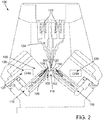
- knitting machine 100 of FIG. 1 has a configuration of a V-bed flat knitting machine as an exemplary embodiment.
- the knitting machine 100 can have different configurations without departing from the scope of the present invention.
- Knitting machine 100 can include a plurality of needles 102 and a plurality of sinkers 104, which are illustrated schematically in FIG. 1 and in greater detail in FIG. 3 .
- Needles 102 can include a plurality of first needles 106
- sinkers 104 can include a plurality of first sinkers 108.
- Needles 102 can further include a plurality of second needles 112 and a plurality of second sinkers 114.
- First needles 106 and first sinkers 108 can be arranged generally in a first bed 110 of knitting machine 100.
- first bed 110 can be substantially planar.
- first needles 106 and first sinkers 108 can be disposed in an alternating arrangement within first bed 110.
- second needles 112 and second sinkers 114 can be arranged in a second bed 116, which can be substantially planar in some embodiments.
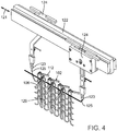
- second needles 112 and second sinkers 114 can be disposed in an alternating arrangement as shown in FIG. 3 .
- first bed 110 can be referred to as a "front bed”
- second bed 116 can be referred to as a "rear bed.”
- First bed 110 and second bed 116 can be spaced apart from each other as shown in FIGS. 1-3 to define a gap 118 between first and second beds 110, 116. Also, as shown in FIGS. 1 and 2 , first bed 110 and second bed 116 can be angled relative to each other. As such, the plane of first bed 110 and the plane of second bed 116 can intersect at an intersection 120 (see FIGS. 2 , 3 and 5 ) that extends along a longitudinal direction 121 of knitting machine 100.
- knitting machine 100 can further include one or more rails 122.
- Rails 122 can be elongate and can extend substantially parallel to the longitudinal direction 121. Rails 122 can provide attachment points for one or more yarn feeders 124.
- Feeders 124 can move longitudinally along the respective rail 122 while feeding yarn 125 toward needles 102. It will be appreciated that feeders 124 can be configured to feed any type of yarn, fiber, wire, cable, filament, or other strand toward needles 102.
- Needles 102 can receive yarn 125 and can perform various knitting procedures for incorporating yarn 125 into a knitted component 129 as represented in FIGS. 4 and 5 .
- needles 102 can knit, tuck, float, inlay, or otherwise manipulate yarn 125 to form knitted component 129.
- Needles 102 can be configured to move relative to intersection 120 and relative to other needles 102 within the respective bed.
- needles 102 can be configured to move between a retracted position and an extended position. Needles 102 are shown in the retracted position with solid lines and in the extended position with broken lines in FIG. 5 . In the retracted position, needle 102 can be spaced apart from intersection 120. In the extended position, needle 102 can be extended through intersection 120. This movement of needles 102 can be substantially linear as represented by arrows 130 in FIG. 5 .
- feeder 124 in addition to moving along the longitudinal direction 121, feeder 124 can be configured to move relative to needles 102 between a retracted position and an extended position.
- feeder 124 In the embodiment of FIG. 5 , feeder 124 is shown in the retracted position with solid lines, and feeder 124 is shown in the extended position with broken lines.
- an end 123 of feeder 124 In the retracted position, an end 123 of feeder 124 can be disposed above the intersection 120 in some embodiments.
- end 123 of feeder 124 In the extended position, end 123 of feeder 124 can be disposed below the intersection 120.
- feeder 124 can feed yarn 125 toward needles 102 to be inlaid within knitted component 129 as represented in FIG. 4 .
- feeder 124 when in the retracted position, feeder 124 can feed yarn 125 toward needles 102 to form loops, tucks, floats, or other features of knitted component 129. Additionally, feeder 124 and other features of knitting machine 100 can be configured according to the teachings of U.S. Patent No. 8,522,577, which issued on September 3, 2013 .
- feeder 124 can have a single, fixed position relative to intersection 120.
- feeder 124 can remain above the intersection 120 as feeder 124 moves in the longitudinal direction 121 of knitting machine 100.
- feeder 124 can remain below the intersection 120 as feeder 124 moves in the longitudinal direction 121 of knitting machine 100.
- Sinkers 104 can be supported on knitting machine 100 for movement relative to other features of knitting machine 100.
- Sinker 104 is configured to move between an open position and a closed position.
- the open position can also be referred to as a "retracted position,” and the closed position can also be referred to as an "extended position.”
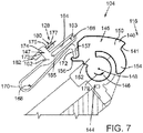
- Sinker 104 is shown in the open position in FIG. 7 according to some embodiments.
- Sinker 104 is shown in the closed position in FIG. 9 according to some embodiments.
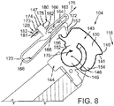
- sinker 104 is shown in an intermediate position in FIG. 8 .
- first sinker 108 of first bed 110 is shown in the closed position while second sinker 114 of second bed 116 is shown in the open position.
- sinker 104 and its movement as illustrated in FIGS. 6-9 and as discussed in detail below, merely represents exemplary embodiments. Thus, sinker 104 can vary from these embodiments without departing from the scope of the present invention.
- sinker 104 can generally include a yarn engaging surface 141.
- Yarn engaging surface 141 can be disposed proximate to the gap 118 that is defined between first bed 110 and second bed 116.
- Yarn engaging surface 141 can move as sinker moves between the open position and the closed position.
- movement of yarn engaging surface 141 can be substantially rotational (i.e., angular) as represented by arrow 178 in FIGS. 6-9 .
- yarn engaging surface 141 can move relative to the gap 118.
- yarn engaging surface 141 can be disposed closer to gap 118 and, in some embodiments, disposed within gap 118 when sinker 104 is in the closed position (see FIGS. 6 and 9 ).
- yarn engaging surface 141 can be disposed further from gap 118 and, in some embodiments, disposed outside gap 118 when sinker 104 is in the open position.
- yarn engaging surface 141 can be disposed closer to a center of the gap 118 in the closed position, and yarn engaging surface 141 can be spaced apart from the center of the gap 118 in the open position.
- this movement of sinker 104 can occur during the knitting process.
- yarn engaging surface 141 of sinker 104 can push downward or otherwise engage the yarn 125 of knitted component 129 as sinker 104 moves toward the closed position.
- This pushing action is represented by arrow 143 in FIG. 6 .
- this operation of sinker 104 can occur in tandem with the movement of the needles 102 to perform the knitting process.
- sinkers 104 can perform known loop formation, hold-down, knock-over, or other functions as knitted component 129 is formed.
- Knitting machine 100 further includes a sinker actuator system 127 for actuating sinkers 104 between the open position and the closed position.
- Actuator system 127 can include one or more cams, electric motors, pneumatic or hydraulic actuators, or other devices that actuate sinkers 104.
- actuator system 127 can include a cam assembly 128.
- Cam assembly 128 is indicated schematically in FIGS. 1 and 2 and is described in detail below according to exemplary embodiments.
- Cam assembly 128 can be supported by a carriage 126 as shown in FIG. 1 .
- Carriage 126 can be supported by rail 122 and can move along rail 122, substantially parallel to the longitudinal direction 121.
- cam assembly 128 can actuate predetermined ones of the sinkers 104.
- cam assembly 128 can include components for actuating predetermined ones of the needles 102.
- carriage 126 can move along rail 122 and a drive bolt or other similar structure can engage feeder 124 to move feeder 124 in the longitudinal direction 121 over first and second beds 110, 116.
- sinker 104 may receive a relatively high force (i.e., an input load) from something other than cam assembly 128.
- sinker 104 can be impacted by another object as sinker 104 moves from the open position toward the closed position.
- sinker 104 can impact feeder 124 as sinker 104 moves toward the closed position as represented in FIG. 12 . This impact force can transfer from sinker 104 to the cam assembly 128.
- cam assembly 128 can include one or more features that allow sinker 104 to move back toward the open position as a result of the input load.
- cam assembly 128 can include "break-away" features that allow sinker 104 to move toward the open position when sinker 104 receives an input load that exceeds a predetermined threshold.
- cam assembly 128 can absorb and dampen forces from sinker 104 and also allow sinker 104 to move more freely under some conditions.
- sinker 104 will be discussed in greater detail. It will be appreciated that other sinkers 104 of knitting machine 100 can correspond to the embodiments illustrated in FIGS. 7-9 and described below. It will also be appreciated that sinkers 104 can vary from these embodiments without departing from the scope of the present invention.
- sinker 104 can include a first member 145, a second member 147, and support structure 144.
- support structure 144 can be fixed to surrounding structures of knitting machine 100.
- First member 145 and/or second member 147 can be attached and supported by support structure 144.
- first member 145 and/or second member 147 can move relative to support structure 144 as sinker 104 moves between the open position and the closed position.
- First member 145 can include a rounded base 146 in some embodiments.
- Base 146 can be attached to the support structure 144 via a pivot joint 148.
- first member 145 can include an arm 150 with a first end 152 and a second end 154.
- First end 152 can be attached to base 146 and can project radially outward from base 146.
- Arm 150 can curve circumferentially about base 146.
- Second end 154 can be disposed proximate to the gap 118 between first needle bed 110 and second needle bed 116.
- First member 145 can also include a hook 156 in some embodiments.
- Hook 156 can project and curve outwardly from arm 150 and can be disposed proximate first end 152.
- first member 145 of sinker 104 can include an outer abutment surface 157.
- Abutment surface 157 can be defined partially on hook 156 and on an outer area of arm 150 that is proximate hook 156. Abutment surface 157 can engage second member 147 of sinker 104 as will be discussed.
- first member 145 can define a head 140.
- head 140 can project radially outwardly from arm 150.
- Head 140 can include yarn engaging surface 141, which is configured to engage the knitted component 129 as shown in FIG. 6 .
- Second member 147 of sinker 104 can include a base 162.
- Base 162 can include an elongate slot 164.
- Slot 164 can be axially straight in some embodiments. Also, slot 164 can receive a post 166 of the support structure 144.
- second member 147 can include an arm 168.
- Arm 168 can extend from base 162 and can be curved in some embodiments. More specifically, arm 168 can extend from base 162 in a direction away from first member 145, and arm 168 can curve at a rear end 170 back toward first member 145 of sinker 104. Additionally, in some embodiments, arm 168 can terminate at a hook end 172. Hook end 172 can abut and engage surface 157 of first member 145.
- Arm 168 can be flexible and resilient in some embodiments. For example, arm 168 can flex to vary the distance between hook end 172 and base 162. This flexibility can ensure engagement between hook end 172 and surface 157 of first member 145 during movement of sinker 104.
- Second member 147 can further include a butt 174 that projects from base 146 in a direction generally away from arm 168.
- butt 174 can be disposed generally between slot 164 and rear end 170 of arm 168.
- Butt 174 can include a first surface 173 and a second surface 175.
- First surface 173 and second surface 175 can face in opposite directions from each other.
- First and second surfaces 173, 175 of butt 174 can abut and engage cam assembly 128 for moving sinker 104 between the open position and the closed position as will be discussed.
- cam assembly 128 can apply a force to second surface 175 of butt 174 as represented by arrow 177.
- second member 147 can be pushed such that post 166 slides toward a first end 163 of slot 164, and hook end 172 pulls back on hook 156 of first member 145.
- First member 145 can, in turn, rotate in a counter-clockwise direction as viewed in FIG. 7 and as indicated by arrow 179.
- cam assembly 128 can apply a force to first surface 173 of butt 174 as represented by arrow 181 in FIGS. 8 and 9 .
- second member 147 can be pushed such that post 166 slides toward a second end 165 of slot 164, and hook end 172 can push against surface 157 of first member 145.
- First member 145 can, in turn, rotate in a clockwise direction as viewed in FIGS. 8 and 9 and as indicated by arrow 178.
- sinker 104 can move back toward the open position when cam assembly 128 applies the force to second surface 174 of butt 174 as represented in FIG. 7 . It will be appreciated, then, that this movement of first and second members 145, 147 of sinker 104 can be reciprocal.
- second member 147 can move substantially in a linear direction (i.e., move along a substantially linear path) as sinker 104 moves between the open position and the closed position. This linear movement can be guided due to abutment and sliding of post 166 within slot 164.
- second member 147 can be referred to as a "linear actuation member" of sinker 104 in some embodiments.
- first member 145 can rotate about pivot joint 148 and can move along a substantially angular path as sinker 104 moves between the open position and the closed position.
- first member 145 can be referred to as a "rotational actuation member" member of sinker 104 in some embodiments.
- sinker 104 is actuated between the closed position and the open position by an actuator system 127, such as a cam assembly 128.
- cam assembly 128 is shown in detail according to exemplary embodiments in FIGS. 10 and 11 .
- components of cam assembly 128 can have predetermined dimensions and shapes. Also, these components can have predetermined positions within knitting machine 100.
- Cam assembly 128 can also have surfaces that engage corresponding parts of the sinkers 104. By engaging sinker 104, cam assembly can push, pull, or otherwise actuate sinker 104 between the open position ( FIG. 7 ) and the closed position ( FIG. 9 ).
- Cam assembly 128 can be mounted for movement relative to sinkers 104.
- cam assembly 128 can be supported by carriage 126. As carriage 126 moves, cam assembly 128 can engage and actuate predetermined ones of the sinkers 104 between the open position and the closed position.
- cam assembly 128 can transfer forces to the sinker 104 for moving the sinker 104.
- sinker 104 can transfer forces to the cam assembly 128, which causes cam assembly 128 to move from a first position to a second position.
- cam assembly 128 can absorb and dampen forces from sinker 104 and also allow sinker 104 to move more freely under some conditions. This can, in turn, allow for a wider range of uses of the knitting machine 100 and allow new types of knitted components to be produced.
- cam assembly 128 can generally include a first cam member 180 and a second cam member 182.
- First cam member 180 can include a first cam surface 184
- second cam member 182 can include a second cam surface 186.
- First and second cam members 180, 182 can be spaced apart at a distance 187.
- first and second surfaces 184, 186 can define a track 188 having a width that is equal to the distance 187 indicated in FIGS. 10 and 11 .
- Distance 187 can be approximately equal to the width of butt 174 of second member 147 of sinker 104.
- track 188 can receive the butt 174 as cam assembly 128 moves over butt 174.
- First and second surfaces 184, 186 can engage and push butt 174 to actuate sinker 104.
- FIGS. 10 and 11 are illustrated such that butt 174 appears to move along track 188 in the direction of arrows 190, this is merely for simplicity.
- carriage 126 rides over sinker 104 causing track to receive butt 174.
- First and second surfaces 184, 186 push butt 174 toward and away from gap 118 defined between first and second beds 110, 116 of knitting machine 100.
- second member 147 rotates first member 145 between the open position and the closed position.
- first and second surfaces 184, 186 defining track 188 can be shaped, sized, and arranged in a wide variety of ways without departing from the scope of the present disclosure.
- FIG. 10 illustrates an exemplary embodiment. Moving from left to right, track 188 can include a lower level segment 201, which leads to an ascending segment 202. Next, track 188 can include an upper level segment 203, which leads to a descending segment 204, and back to another lower level segment 201. In this configuration, sinker 104 can be in the open position shown in FIG. 7 when butt 174 is moving within lower level segment 201. Sinker 104 can be in the intermediate position, similar to FIG. 8 , when moving within the ascending segment 202.
- Sinker 104 can be in the closed position of FIG. 9 when in the upper level segment 203. Then, sinker 104 can move back to the intermediate position of when moving in the descending segment 204, then to the open position when moving in the next lower level segment 201, and so on.
- second cam surface 186 can abut and push butt 174 of sinker 104 as butt 174 travels in the ascending segment 202 to move sinker 104 toward the closed position.
- first cam surface 184 can abut and push butt 174 of sinker 104 as butt 174 travels in the descending segment 204 to move sinker 104 toward the open position.
- first cam member 180 can be a unitary member such that portions of track 188 defined by first cam surface 184 are substantially fixed.
- second cam member 182 can include a support structure 220 with one or more openings 222.
- support structure 220 can include two openings 222 that are spaced apart along track 188.
- support structure 220 can define lower level segments 201 of track 188. Openings 22 can be disposed in ascending segment 202, upper level segment 203, and descending segment 204.
- Second cam member 182 can also include one or more biased cam members 224.
- Biased cam member 224 can be received within opening 222.
- two biased cam members 224 are shown, and each biased cam member 224 is received within a respective opening 222.
- Biased cam members 224 can include an ascending surface 226, a plateau surface 228, and a descending surface 230. Plateau surface 228 can extend between ascending surface 226 and descending surface 230. Biased cam members 224 can further include a peripheral side 229 and an underside 231. Peripheral side 229 can extend about a lower periphery of cam member 224, for example, at the outer periphery of underside 231. Also, underside 231 can face the bottom 236 of opening 222.
- biased cam member 224 When attached to support structure 220, biased cam member 224 can cooperate to define track 188.
- ascending surface 226 and first cam surface 184 can cooperate to define ascending segment 202 of track 188.
- Plateau surface 228 and first cam surface 184 can cooperate to define upper level segment 203 of track 188.
- Descending surface 230 and first cam surface 184 can cooperate to define descending segment 204.
- the size of opening 222 can correspond to the size of biased cam member 224.
- biased cam member 224 can move into and out of opening 222 between a first position and a second position.
- FIGS. 10 and 11 show biased cam member 224 in a first position, substantially extended out of opening 222 according to exemplary embodiments.
- FIGS. 13 and 14 show biased cam member 224 in a second position, substantially recessed into opening 222 according to exemplary embodiments.
- sides 235 of opening 222 can be proximate to the peripheral side 229 of biased cam member 224.
- sides 235 and/or structures supported by sides 235 can engage biased cam member 224 to guide movement of biased cam member 224 into and out of opening 222.
- peripheral side 229 of biased cam member 224 can abut and slide along sides 235 of opening 222 when moving between the first position ( FIGS. 10 and 11 ) and the second position ( FIGS. 13 and 14 ).
- support structure 220 and biased cam member 224 can have interlocking sliders, tongue-and-groove attachments, or other types of couplings that support this sliding movement.
- second cam member 182 can include one or more biasing members 232.
- biasing members 232 can be helical compression springs 234.
- biasing members 232 could include hydraulic springs, leaf springs, pneumatic springs, or other types of biasing members.
- Biasing members 232 can be attached at one end to the bottom 236 of opening 222 and attached at the opposite end to the underside 231 of the biased cam member 224.
- cam assembly 128 can include any number of biasing members 232.
- each biased cam member 224 is supported by two respective biasing members 232.
- biasing members 232 can bias cam member 224 toward the first position represented in FIGS. 10 and 11 .
- Biasing members 232 can have a predetermined spring constant for providing a predetermined level of biasing force to cam member 224.
- cam assembly 128 can actuate sinker 104 between the open position and the closed position. This is explained in detail above according to exemplary embodiments. Assuming that any reaction forces transferred from the sinker 104 to the biased cam members 224 are less than the biasing force provided by biasing members 232, the biased cam members 224 will remain in the first position causing sinkers 104 to reciprocate between the open and closed positions.
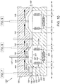
- FIG. 12 shows a condition in which sinker 104 impacts the yarn feeder 124.
- the cam assembly 128 is shown pushing upward on the butt 174 of the second sinker member 147, causing the first sinker member 145 to rotate into the gap 118 toward its closed position.
- the feeder 124 happens to be in the way, and the head 140 of the first sinker member 145 impacts the feeder 124.
- the feeder 124 imparts a resulting reaction force onto the first sinker member 145.
- This reaction force can be referred to as an input force imparted to the first sinker member 145, which is represented by arrow 240.
- the input force 240 can be transferred from the first sinker member 145 to the second sinker member 147 as represented in FIGS. 13 and 14 . As shown, the input force 240 can cause second sinker member 147 to push downward on biased cam member 224, against the biasing force supplied by biasing member 232.
- biased cam member 224 can recess into opening 222.
- the input force 240 can cause biased cam member 224 to move away from the first position ( FIGS. 10 and 11 ) toward the second position ( FIGS. 13 and 14 ).
- the width 187 of track 188 measured between first cam surface 184 and second cam surface 186 of cam member 224 can increase as cam member 224 moves toward the second position.
- cam assembly 128 releases sinker 104 and allows sinker 104 to move away from its closed position ( FIG. 9 ), back toward its open position ( FIG. 7 ).
- biasing member 232 can bias cam member 224 back toward the first position ( FIGS. 10 and 11 ). For example, once carriage 126 and cam assembly 128 bypasses sinker 104, the input force 240 can be reduced on cam member 224 to allow cam member 224 to bias back toward the first position.
- Biasing member 232 can provide a predetermined threshold biasing force that biases cam member 224 toward the first position. If the input force 240 resulting from the impact with feeder 124 exceeds the predetermined threshold force, then biased cam member 224 can recess into opening 222 toward its second position. However, if the input force 240 is below the threshold, then cam member 224 can remain in its first position. It will be appreciated that the predetermined threshold force can be selected to allow the biased cam member 224 to move to the second position under the influence of relatively high loads, such as when impacting the feeder 124. However, the threshold can be high enough to retain the biased cam member 224 in the first position under the influence of lower loads, such as during normal knitting operations.
- the threshold force provided by biasing member 232 can be varied between a first threshold force and a second threshold force.
- the biasing member 232 can have a variable stiffness.
- the cam assembly 128 can include an actuator 250 that is operably connected to the biasing member 232.
- the actuator 250 is represented schematically in FIGS. 10 and 13 . It will be appreciated that the actuator 250 can be an electric motor, a pneumatic actuator, a hydraulic actuator, or another type of actuator.
- the actuator 250 can be configured to actuate to vary the threshold biasing force provided by the biasing member 232.
- the actuator 250 can actuate to change the length of the biasing member 232 to vary the threshold force. Accordingly, in some embodiments, the user can actuate the actuator 250 and increase the threshold biasing force when desired. Alternatively, the user can actuate the actuator 250 to decrease the threshold biasing force when desired.
- the cam assembly 128 of the knitting machine 100 can actuate the sinkers 104 in an efficient and effective manner for facilitating the knitting process.
- the cam assembly 128 can allow the sinker 104 to move back toward the open position.
- the cam assembly 128 can give way and allow the sinker 104 to move back toward the open position.
- the sinker 104 impacts the feeder 124 when moving toward the closed position, the sinker 104 can push back on the cam assembly 128.
- the cam assembly 128 can, in turn, allow the sinker 104 to move back toward the open position.
- cam assembly 128 can absorb and dampen forces from sinker 104. Additionally, in some embodiments, the feeder 124 can remain within the gap 118 below the intersection 120 of the beds 110, 116 of the knitting machine 100. Accordingly, the feeder 124 can be used in a wide variety of positions relative to the beds 110, 116 of the knitting machine 100.
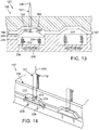
- a knitting machine 300 includes a feeder 324 or may include a feeder 324 and a sinker 314 with a surface shaped to facilitate movement of the sinker from the closed position to the open position when the feeder 324 impacts the sinker 314.
- the feeder 324 includes an end portion 323 with a first ramped surface 340.
- the first ramped surface 340 may correspond with a second ramped surface 342 on the sinker 314.
- the feeder 324 moves in the feed direction 320 along the rail 322, it may impact the sinker 314.
- the feeder 324 and/or the sinker 314 may be configured such that when this impact occurs, the first ramped surface 340 of the feeder 324 contacts the second ramped surface 342 of the sinker 314.
- the ramped surfaces 340 and 342 may be shaped or otherwise configured such that the contact between the ramped surfaces 340 and 342 creates an input force that initiates a movement of the sinker 314 to allow the feeder 324 to bypass the sinker 314. This may prevent damaging the components of the knitting machine 300 and may allow the feeder 324 to continue its motion in the feed direction 320.
- a feeder 424 includes an end portion 423 with a ramped surface 440, which here is a curved ramped surface circumnavigating the end portion 423.
- the ramped surface 440 may be located such that when the feeder 424 impacts the sinker 414, the ramped surface 440 contacts the sinker 414.
- the ramped surface may be configured such that contact between the feeder 424 the sinker 414, which may be a conventional off-the-shelf sinker not specifically designed to have a ramped surface, causes the sinker 414 to rotate in a direction as indicated by arrow 478 to an open position, thereby preventing damage to the sinker 414 and/or the feeder 424 and allowing the feeder 424 to pass.
- the ramped surface 440 of the feeder 424 may extend around substantially the entirety of the end portion 423 to correspond to sinkers located on multiple sides of the feeder 424 and such that any rotation of the feeder 424 along its longitudinal axis will not misalign the ramped surface 440 with the sinker 414.
- the sinker 414 may additionally include a ramped surface configured to cause rotation of the sinker 414 in the direction indicated by arrow 478. It is contemplated that the feeder 424 or the feeder 424 and the sinker 414 may additionally or alternatively include an attachment having a ramped surface.
- the ramped surface on the feeder or on the feeder and the sinker is particularly advantageous when the knitting machine 400 includes a biasing member (e.g., biasing member 232 of FIG. 10 ).
- a biasing member may provide a predetermined level of biasing force to the sinker 414 in the clockwise direction (e.g., towards a closed position as described in detail above with reference to FIG. 10 ).
- the ramped surface 440 will contact the sinker 414.
- the resulting reaction force may be sufficient to overcome the biasing force, thereby causing the sinker 414 to rotate in the counterclockwise direction (indicated by arrow 478) such that that the feeder 424 can bypass the sinker 414.
- the biasing force provided by the biasing member may then cause clockwise motion of the sinker 414 to move it back into the closed position such that the sinker 414 continues to perform the desired function.
Landscapes
- Engineering & Computer Science (AREA)
- Textile Engineering (AREA)
- Knitting Machines (AREA)
Claims (15)
- Strickmaschine (100) zum Stricken einer Strickkomponente (129), die Folgendes aufweist:eine Platine (104), die so ausgestaltet ist, dass sie sich zwischen einer offenen Position und einer geschlossenen Position bewegt; undein Platinenbetätigungssystem (127) mit einer ersten Ausgestaltung und einer zweiten Ausgestaltung;wobei das Platinenbetätigungssystem (127) in der ersten Ausgestaltung so ausgestaltet ist, dass es die Platine (104) von der offenen Position zur geschlossenen Position betätigt;wobei die Platine (104) so ausgestaltet ist, dass sie das Platinenbetätigungssystem (127) von der ersten Ausgestaltung in die zweite Ausgestaltung überführt, wenn die Platine (104) bei der Bewegung von der offenen Position zur geschlossenen Position eine Eingangskraft erhält, die über einem vorbestimmten Schwellenwert liegt; undwobei das Platinenbetätigungssystem (127) in der zweiten Ausgestaltung so ausgestaltet ist, dass es die Platine (104) von der geschlossenen Position weg zur offenen Position bewegt,wobei die Strickmaschine ferner eine Fadenzuführeinrichtung (324, 424) aufweist,wobei die Strickmaschine (100) dadurch gekennzeichnet ist, dass eine erste rampenförmige Fläche (340) der Fadenzuführeinrichtung (324, 424) so ausgestaltet ist, dass sie die Platine (104) berührt, um die Eingangskraft bereitzustellen, wenn die Platine (104) auf die Fadenzuführeinrichtung (324, 424) auftrifft.
- Strickmaschine (100) nach Anspruch 1, wobei das Platinenbetätigungssystem (127) eine Nockenanordnung (128) aufweist mit:einem Nockenelement (224), das so ausgestaltet ist, dass es sich zwischen einer ersten Position und einer zweiten Position bewegt;einem Vorspannelement (232), das das Nockenelement mit einer vorbestimmten Schwellenkraft zur ersten Position vorspannt;wobei sich das Nockenelement in der ersten Position befindet, wenn sich das Platinenbetätigungssystem in der ersten Ausgestaltung befindet;wobei sich das Nockenelement in der zweiten Position befindet, wenn sich das Platinenbetätigungssystem in der zweiten Ausgestaltung befindet;wobei das Nockenelement in der ersten Position so ausgestaltet ist, dass es sich in Bezug auf die Platine (104) bewegt, um die Platine weg von der offenen Position zur geschlossenen Position zu betätigen;wobei das Nockenelement so ausgestaltet ist, dass es die Eingangskraft von der Platine erhält, die das Nockenelement weg von der ersten Position in die zweite Position bewegt, wenn die Eingangskraft die vorbestimmte Schwellenkraft überschreitet, wodurch sich die Platine weg von der geschlossenen Position zur offenen Position bewegen kann.
- Strickmaschine (100) nach einem der Ansprüche 1-2, wobei die Platine (104) eine zweite rampenförmige Fläche (342) aufweist, die so ausgestaltet ist, dass sie die Fadenzuführeinrichtung (324, 424) berührt, wenn die Platine auf die Fadenzuführeinrichtung auftrifft.
- Strickmaschine (100) nach einem der Ansprüche 2-3, wobei es sich bei dem Nockenelement (224) um ein erstes Nockenelement (180) handelt, das zumindest teilweise eine erste Nockenfläche (184) der Platinennockenbaugruppe (128) definiert;
wobei die Platinennockenbaugruppe ein zweites Nockenelement (182) aufweist, das zumindest teilweise eine zweite Nockenfläche (186) der Platinennockenbaugruppe definiert;
wobei die erste Nockenfläche von der zweiten Nockenfläche beabstandet ist, um eine Bahn (188) zwischen der ersten Nockenfläche und der zweiten Nockenfläche zu definieren;
wobei die Bahn eine zwischen der ersten Nockenfläche und der zweiten Nockenfläche gemessene Breite hat; und
wobei sich die Breite der Bahn in der Nähe des ersten Nockenelements verändert, wenn sich das erste Nockenelement zwischen der ersten Position und der zweiten Position bewegt. - Strickmaschine (100) nach Anspruch 4, wobei die erste Nockenfläche (184) so ausgestaltet ist, dass sie an die Platine (104) stößt und die Platine weg von der offenen Position zur geschlossenen Position betätigt; und
wobei die zweite Nockenfläche (186) so ausgestaltet ist, dass sie an die Platine stößt und die Platine weg von der geschlossenen Position zur offenen Position betätigt. - Strickmaschine (100) nach einem der Ansprüche 2-5, die ferner ein erstes Nadelbett (110) mit mehreren ersten Nadeln (106) aufweist, die im Wesentlichen innerhalb einer ersten Ebene angeordnet sind;
die ferner ein zweites Nadelbett (116) mit mehreren zweiten Nadeln (112) aufweist, die im Wesentlichen innerhalb einer zweiten Ebene angeordnet sind;
wobei sich die erste Ebene und die zweite Ebene in einem Schnittpunkt (120) schneiden;
wobei ein erster Bereich über dem Schnittpunkt definiert ist und ein zweiter Bereich unter dem Schnittpunkt definiert ist;
wobei die Fadenzuführeinrichtung (324, 424) so ausgestaltet ist, dass sie sich innerhalb des zweiten Bereichs in Bezug auf das erste und das zweite Nadelbett bewegt; und
wobei die Platine (104) so ausgestaltet ist, dass sie auf die Fadenzuführeinrichtung auftrifft und aufgrund des Auftreffens die Eingangskraft zum Nockenelement (224) überträgt. - Strickmaschine (100) nach einem der Ansprüche 2-6, wobei die vorbestimmte Schwellenkraft zwischen einer ersten Schwellenkraft und einer zweiten Schwellenkraft einstellbar ist, wobei die Strickmaschine (100) vorzugsweise ferner eine Betätigungseinrichtung (250) aufweist, die so ausgestaltet ist, dass sie zum Einstellen der Schwellenkraft des Vorspannelements (232) zwischen der ersten Schwellenkraft und der zweiten Schwellenkraft betätigt.
- Strickmaschine (100) nach einem der Ansprüche 2-7, wobei die Platine (104) ein erstes Element (145) und ein zweites Element (147) aufweist;
wobei das erste Element eine Fadenangriffsfläche (141) aufweist, die so ausgestaltet ist, dass sie die Strickkomponente (129) berührt;
wobei das Nockenelement (224) in der ersten Position so ausgestaltet ist, dass es an das zweite Element stößt und das zweite Element betätigt, welches das erste Element betätigt und die Fadenangriffsfläche bewegt. - Strickmaschine (100) nach Anspruch 8, wobei das zweite Element (147) so ausgestaltet ist, dass es sich entlang einer im Wesentlichen linearen Bahn bewegt, wenn sich die Platine (104) zwischen der offenen Position und der geschlossenen Position bewegt; und
wobei das erste Element (145) so ausgestaltet ist, dass es sich entlang einer im Wesentlichen winkelförmigen Bahn bewegt, wenn sich die Platine zwischen der offenen Position und der geschlossenen Position bewegt. - Stickmaschine (100) nach einem der Ansprüche 2-9, wobei das Nockenelement (224) von einer Stützstruktur (220) gestützt ist;
wobei sich das Nockenelement in Bezug auf die Stützstruktur bewegt, wenn es sich zwischen der ersten Position und der zweiten Position bewegt; und
wobei das Vorspannelement (232) an der Stützstruktur und an dem Nockenelement befestigt ist. - Verfahren zum Betätigen einer Platine (104) einer Strickmaschine (100) zwischen einer offenen Position und einer geschlossenen Position; wobei das Verfahren Folgendes umfasst:Bereitstellen eines Platinenbetätigungssystems (127) mit einer ersten Ausgestaltung und einer zweiten Ausgestaltung;Betätigen der Platine (104) von der offenen Position zur geschlossenen Position, wobei sich das Platinenbetätigungssystem (127) in der ersten Ausgestaltung befindet;Überführen des Platinenbetätigungssystems (127) von der ersten Ausgestaltung in die zweite Ausgestaltung mit der Platine (104), wenn die Platine (104) bei der Bewegung von der offenen Position zur geschlossenen Position eine Eingangskraft erhält, die über einem vorbestimmten Schwellenwert liegt;Bewegen der Platine (104) weg von der geschlossenen Position zur offenen Position, wobei sich das Platinenbetätigungssystem (127) in der zweiten Ausgestaltung befindet;dadurch gekennzeichnet, dass das Verfahren ferner Folgendes umfasst:Bereitstellen einer Fadenzuführeinrichtung (324, 424);Kontaktieren der Platine (104) mit einer ersten rampenförmigen Fläche (340) der Fadenzuführeinrichtung (324, 424), um die Eingangskraft bereitzustellen, wenn die Platine (104) auf die Fadenzuführeinrichtung (324, 424) auftrifft.
- Verfahren nach Anspruch 11, wobei das Verfahren ferner Folgendes umfasst:Bereitstellen eines Nockenelements (224) einer Nockenbaugruppe (128), die Teil des Platinenbetätigungssystems (127) ist, wobei das Nockenelement (224) so ausgestaltet ist, dass es sich zwischen einer ersten Position und einer zweiten Position bewegt;Vorspannen des Nockenelements (224) mit einer vorbestimmten Schwellenkraft zur ersten Position mit einem Vorspannelement (232);Bewegen des Nockenelements (224) in Bezug auf die Platine (104), wenn sich das Nockenelement (224) in der ersten Position befindet, um die Platine (104) von der offenen Position zur geschlossenen Position zu bewegen; undBewegen des Nockenelements (224) in Bezug auf die Platine (104), was dazu führt, dass das Nockenelement (224) eine Eingangskraft von der Platine (104) erhält;Bewegen des Nockenelements (224) weg von der ersten Position in die zweite Position, wenn die Eingangskraft die vorbestimmte Schwellenkraft überschreitet, wodurch sich die Platine (104) weg von der geschlossenen Position zur offenen Position bewegen kann,wobei der Schritt des Kontaktierens der Platine (104) mit einer ersten rampenförmigen Fläche (340) der Fadenzuführeinrichtung (324, 424) das Bereitstellen der Eingangskraft umfasst, wenn sich das Nockenelement (224) weg von der ersten Position in die zweite Position bewegt.
- Verfahren nach Anspruch 12, wobei die Nockenbaugruppe (128) eine Stützstruktur (220) mit einer Öffnung (222) aufweist, die das Nockenelement (224) aufnimmt, und das ferner das Versenken des Nockenelements in der Öffnung umfasst, wenn sich das Nockenelement von der ersten Position in die zweite Position bewegt.
- Verfahren nach einem der Ansprüche 11-13, das ferner das Verändern der vorbestimmten Schwellenkraft umfasst.
- Verfahren nach Anspruch 14, wobei das Verändern der vorbestimmten Schwellenkraft das Betätigen einer Betätigungseinrichtung (250) umfasst, die die vorbestimmte Schwellenkraft verändert.
Applications Claiming Priority (2)
| Application Number | Priority Date | Filing Date | Title |
|---|---|---|---|
| US201562108625P | 2015-01-28 | 2015-01-28 | |
| PCT/US2016/015126 WO2016123218A1 (en) | 2015-01-28 | 2016-01-27 | Knitting machine with biased cam member for actuating a sinker |
Publications (2)
| Publication Number | Publication Date |
|---|---|
| EP3250737A1 EP3250737A1 (de) | 2017-12-06 |
| EP3250737B1 true EP3250737B1 (de) | 2019-09-25 |
Family
ID=55405459
Family Applications (1)
| Application Number | Title | Priority Date | Filing Date |
|---|---|---|---|
| EP16705870.0A Active EP3250737B1 (de) | 2015-01-28 | 2016-01-27 | Strickmaschine mit vorgespanntem nockenelement zur betätigung einer platine |
Country Status (4)
| Country | Link |
|---|---|
| US (1) | US10294594B2 (de) |
| EP (1) | EP3250737B1 (de) |
| CN (1) | CN107429450B (de) |
| WO (1) | WO2016123218A1 (de) |
Families Citing this family (1)
| Publication number | Priority date | Publication date | Assignee | Title |
|---|---|---|---|---|
| CN118390233B (zh) * | 2024-05-09 | 2025-09-19 | 浙江丰帆数控机械有限公司 | 一种针织横机的沉降片驱动机构 |
Citations (1)
| Publication number | Priority date | Publication date | Assignee | Title |
|---|---|---|---|---|
| US2705409A (en) * | 1954-02-03 | 1955-04-05 | Karl Lieberknecht Inc | Yarn carrier for full fashioned knitting machines |
Family Cites Families (15)
| Publication number | Priority date | Publication date | Assignee | Title |
|---|---|---|---|---|
| US2067877A (en) * | 1934-01-10 | 1937-01-12 | Hemphill Co | Knitting machine |
| US2123534A (en) * | 1934-08-09 | 1938-07-12 | Hemphill Co | Cam block for knitting machines |
| KR0123800B1 (ko) * | 1989-12-28 | 1997-11-27 | 마사히로 시마 | 횡편기에 있어서의 싱카장치 |
| JP2618312B2 (ja) * | 1992-07-09 | 1997-06-11 | 株式会社島精機製作所 | 横編機におけるシンカー装置 |
| JP2700204B2 (ja) * | 1992-12-15 | 1998-01-19 | 株式会社島精機製作所 | 横編機におけるシンカー装置 |
| JP3140990B2 (ja) * | 1997-08-11 | 2001-03-05 | 株式会社島精機製作所 | 可動ループ形成プレートを備えた横編機 |
| CN2422305Y (zh) * | 2000-01-04 | 2001-03-07 | 李宾 | 横编织机沉降片控制装置 |
| EP1655398B1 (de) * | 2003-07-30 | 2011-04-20 | Shima Seiki Manufacturing, Ltd. | Kulierstrick- oder kulierwirkmaschine mit bewegbarer platine |
| DE50309083D1 (de) * | 2003-10-07 | 2008-03-13 | Stoll & Co H | Flachstrickmaschine mit mindestens einem Nadelbett |
| US7152436B2 (en) * | 2004-01-20 | 2006-12-26 | Pai Lung Machinery Mill Co., Ltd. | Circular knitting machine |
| JP4176038B2 (ja) * | 2004-03-31 | 2008-11-05 | 株式会社島精機製作所 | 横編機の可動シンカー装置 |
| EP1956126B1 (de) * | 2007-02-08 | 2013-08-21 | H. Stoll GmbH & Co. KG | Flachstrickmaschine |
| CN201722489U (zh) * | 2010-06-12 | 2011-01-26 | 松谷机械(惠州)有限公司 | 一种附加小机头 |
| CN101962866B (zh) * | 2010-10-28 | 2011-09-14 | 宁波慈星股份有限公司 | 沉降片控制装置 |
| US8522577B2 (en) | 2011-03-15 | 2013-09-03 | Nike, Inc. | Combination feeder for a knitting machine |
-
2016
- 2016-01-27 EP EP16705870.0A patent/EP3250737B1/de active Active
- 2016-01-27 WO PCT/US2016/015126 patent/WO2016123218A1/en not_active Ceased
- 2016-01-27 CN CN201680015076.9A patent/CN107429450B/zh active Active
-
2017
- 2017-07-25 US US15/659,124 patent/US10294594B2/en active Active
Patent Citations (1)
| Publication number | Priority date | Publication date | Assignee | Title |
|---|---|---|---|---|
| US2705409A (en) * | 1954-02-03 | 1955-04-05 | Karl Lieberknecht Inc | Yarn carrier for full fashioned knitting machines |
Also Published As
| Publication number | Publication date |
|---|---|
| CN107429450A (zh) | 2017-12-01 |
| EP3250737A1 (de) | 2017-12-06 |
| WO2016123218A1 (en) | 2016-08-04 |
| CN107429450B (zh) | 2019-10-15 |
| US20170321358A1 (en) | 2017-11-09 |
| US10294594B2 (en) | 2019-05-21 |
Similar Documents
| Publication | Publication Date | Title |
|---|---|---|
| CN1250793C (zh) | 横机的沉降片装置 | |
| US3828582A (en) | Improved knitting machine equipped with two part needles | |
| EP1260625B1 (de) | Fadenführerschlitten einer schussstrickmaschine | |
| US6988385B2 (en) | Yarn feeder of weft knitting machine and method of feeding yarn for weft knitting machine | |
| US4584851A (en) | Knitting machine for producing mesh products | |
| KR20030086595A (ko) | 횡편기의 얀 피더 | |
| EP3250737B1 (de) | Strickmaschine mit vorgespanntem nockenelement zur betätigung einer platine | |
| EP2363519B1 (de) | Garneinspann- und Schneidevorrichtung, insbesondere für Ringeleinrichtungen von Strickmaschinen oder dergleichen | |
| EP0533414B1 (de) | Flachstrickmaschine | |
| US4574596A (en) | Stitch-forming machine | |
| EP2789718B1 (de) | Flachstrickmaschine mit beweglicher Platine | |
| US6422044B1 (en) | Needle actuation device for knitting machines for hosiery or other articles | |
| EP2354284B1 (de) | Strickverfahren in Plattiertechnik | |
| EP2392710B1 (de) | Flachstrickmaschine | |
| KR102534407B1 (ko) | 환편기용 싱커 캠 | |
| HK1247649A1 (en) | Knitting machine with biased cam member for actuating a sinker | |
| EP2570537B1 (de) | Fadenführer für eine Flachstrickmaschine | |
| TW202300745A (zh) | 申克片、針織裝置與用於生產針織物的針織方法 | |
| JP2004316026A (ja) | 編成タイミング切換装置を備えた丸編機 | |
| HK1247649B (zh) | 具有用於致动沉降片的偏压凸轮构件的针织机 | |
| CN111793889B (zh) | 横机 | |
| CN101962867B (zh) | 具有可竖直和水平移位的导纱器臂的横机 | |
| EP2240634B1 (de) | Nadel zur maschenübertragung von der nadel selbst auf benachbarte nadeln für wirkmaschinen oder dergleichen | |
| US7047769B2 (en) | Loop-forming system and sinker for such a system | |
| KR20020094055A (ko) | 코 이동 기구를 구비하는 횡편기 |
Legal Events
| Date | Code | Title | Description |
|---|---|---|---|
| STAA | Information on the status of an ep patent application or granted ep patent |
Free format text: STATUS: THE INTERNATIONAL PUBLICATION HAS BEEN MADE |
|
| PUAI | Public reference made under article 153(3) epc to a published international application that has entered the european phase |
Free format text: ORIGINAL CODE: 0009012 |
|
| STAA | Information on the status of an ep patent application or granted ep patent |
Free format text: STATUS: REQUEST FOR EXAMINATION WAS MADE |
|
| 17P | Request for examination filed |
Effective date: 20170809 |
|
| AK | Designated contracting states |
Kind code of ref document: A1 Designated state(s): AL AT BE BG CH CY CZ DE DK EE ES FI FR GB GR HR HU IE IS IT LI LT LU LV MC MK MT NL NO PL PT RO RS SE SI SK SM TR |
|
| AX | Request for extension of the european patent |
Extension state: BA ME |
|
| DAV | Request for validation of the european patent (deleted) | ||
| DAX | Request for extension of the european patent (deleted) | ||
| STAA | Information on the status of an ep patent application or granted ep patent |
Free format text: STATUS: EXAMINATION IS IN PROGRESS |
|
| 17Q | First examination report despatched |
Effective date: 20180816 |
|
| REG | Reference to a national code |
Ref country code: DE Ref legal event code: R079 Ref document number: 602016021194 Country of ref document: DE Free format text: PREVIOUS MAIN CLASS: D04B0015060000 Ipc: D04B0015800000 |
|
| GRAP | Despatch of communication of intention to grant a patent |
Free format text: ORIGINAL CODE: EPIDOSNIGR1 |
|
| STAA | Information on the status of an ep patent application or granted ep patent |
Free format text: STATUS: GRANT OF PATENT IS INTENDED |
|
| RIC1 | Information provided on ipc code assigned before grant |
Ipc: D04B 15/90 20060101ALI20190319BHEP Ipc: D04B 15/80 20060101AFI20190319BHEP Ipc: D04B 15/70 20060101ALI20190319BHEP Ipc: D04B 15/06 20060101ALI20190319BHEP Ipc: D04B 15/36 20060101ALI20190319BHEP |
|
| INTG | Intention to grant announced |
Effective date: 20190408 |
|
| GRAS | Grant fee paid |
Free format text: ORIGINAL CODE: EPIDOSNIGR3 |
|
| GRAA | (expected) grant |
Free format text: ORIGINAL CODE: 0009210 |
|
| STAA | Information on the status of an ep patent application or granted ep patent |
Free format text: STATUS: THE PATENT HAS BEEN GRANTED |
|
| AK | Designated contracting states |
Kind code of ref document: B1 Designated state(s): AL AT BE BG CH CY CZ DE DK EE ES FI FR GB GR HR HU IE IS IT LI LT LU LV MC MK MT NL NO PL PT RO RS SE SI SK SM TR |
|
| REG | Reference to a national code |
Ref country code: GB Ref legal event code: FG4D |
|
| REG | Reference to a national code |
Ref country code: CH Ref legal event code: EP |
|
| REG | Reference to a national code |
Ref country code: AT Ref legal event code: REF Ref document number: 1183921 Country of ref document: AT Kind code of ref document: T Effective date: 20191015 |
|
| REG | Reference to a national code |
Ref country code: IE Ref legal event code: FG4D |
|
| REG | Reference to a national code |
Ref country code: DE Ref legal event code: R096 Ref document number: 602016021194 Country of ref document: DE |
|
| REG | Reference to a national code |
Ref country code: NL Ref legal event code: MP Effective date: 20190925 |
|
| PG25 | Lapsed in a contracting state [announced via postgrant information from national office to epo] |
Ref country code: NO Free format text: LAPSE BECAUSE OF FAILURE TO SUBMIT A TRANSLATION OF THE DESCRIPTION OR TO PAY THE FEE WITHIN THE PRESCRIBED TIME-LIMIT Effective date: 20191225 Ref country code: BG Free format text: LAPSE BECAUSE OF FAILURE TO SUBMIT A TRANSLATION OF THE DESCRIPTION OR TO PAY THE FEE WITHIN THE PRESCRIBED TIME-LIMIT Effective date: 20191225 Ref country code: LT Free format text: LAPSE BECAUSE OF FAILURE TO SUBMIT A TRANSLATION OF THE DESCRIPTION OR TO PAY THE FEE WITHIN THE PRESCRIBED TIME-LIMIT Effective date: 20190925 Ref country code: FI Free format text: LAPSE BECAUSE OF FAILURE TO SUBMIT A TRANSLATION OF THE DESCRIPTION OR TO PAY THE FEE WITHIN THE PRESCRIBED TIME-LIMIT Effective date: 20190925 Ref country code: HR Free format text: LAPSE BECAUSE OF FAILURE TO SUBMIT A TRANSLATION OF THE DESCRIPTION OR TO PAY THE FEE WITHIN THE PRESCRIBED TIME-LIMIT Effective date: 20190925 Ref country code: SE Free format text: LAPSE BECAUSE OF FAILURE TO SUBMIT A TRANSLATION OF THE DESCRIPTION OR TO PAY THE FEE WITHIN THE PRESCRIBED TIME-LIMIT Effective date: 20190925 |
|
| REG | Reference to a national code |
Ref country code: LT Ref legal event code: MG4D |
|
| PG25 | Lapsed in a contracting state [announced via postgrant information from national office to epo] |
Ref country code: GR Free format text: LAPSE BECAUSE OF FAILURE TO SUBMIT A TRANSLATION OF THE DESCRIPTION OR TO PAY THE FEE WITHIN THE PRESCRIBED TIME-LIMIT Effective date: 20191226 Ref country code: LV Free format text: LAPSE BECAUSE OF FAILURE TO SUBMIT A TRANSLATION OF THE DESCRIPTION OR TO PAY THE FEE WITHIN THE PRESCRIBED TIME-LIMIT Effective date: 20190925 Ref country code: RS Free format text: LAPSE BECAUSE OF FAILURE TO SUBMIT A TRANSLATION OF THE DESCRIPTION OR TO PAY THE FEE WITHIN THE PRESCRIBED TIME-LIMIT Effective date: 20190925 |
|
| REG | Reference to a national code |
Ref country code: AT Ref legal event code: MK05 Ref document number: 1183921 Country of ref document: AT Kind code of ref document: T Effective date: 20190925 |
|
| PG25 | Lapsed in a contracting state [announced via postgrant information from national office to epo] |
Ref country code: AL Free format text: LAPSE BECAUSE OF FAILURE TO SUBMIT A TRANSLATION OF THE DESCRIPTION OR TO PAY THE FEE WITHIN THE PRESCRIBED TIME-LIMIT Effective date: 20190925 Ref country code: PT Free format text: LAPSE BECAUSE OF FAILURE TO SUBMIT A TRANSLATION OF THE DESCRIPTION OR TO PAY THE FEE WITHIN THE PRESCRIBED TIME-LIMIT Effective date: 20200127 Ref country code: IT Free format text: LAPSE BECAUSE OF FAILURE TO SUBMIT A TRANSLATION OF THE DESCRIPTION OR TO PAY THE FEE WITHIN THE PRESCRIBED TIME-LIMIT Effective date: 20190925 Ref country code: PL Free format text: LAPSE BECAUSE OF FAILURE TO SUBMIT A TRANSLATION OF THE DESCRIPTION OR TO PAY THE FEE WITHIN THE PRESCRIBED TIME-LIMIT Effective date: 20190925 Ref country code: EE Free format text: LAPSE BECAUSE OF FAILURE TO SUBMIT A TRANSLATION OF THE DESCRIPTION OR TO PAY THE FEE WITHIN THE PRESCRIBED TIME-LIMIT Effective date: 20190925 Ref country code: AT Free format text: LAPSE BECAUSE OF FAILURE TO SUBMIT A TRANSLATION OF THE DESCRIPTION OR TO PAY THE FEE WITHIN THE PRESCRIBED TIME-LIMIT Effective date: 20190925 Ref country code: RO Free format text: LAPSE BECAUSE OF FAILURE TO SUBMIT A TRANSLATION OF THE DESCRIPTION OR TO PAY THE FEE WITHIN THE PRESCRIBED TIME-LIMIT Effective date: 20190925 Ref country code: NL Free format text: LAPSE BECAUSE OF FAILURE TO SUBMIT A TRANSLATION OF THE DESCRIPTION OR TO PAY THE FEE WITHIN THE PRESCRIBED TIME-LIMIT Effective date: 20190925 Ref country code: ES Free format text: LAPSE BECAUSE OF FAILURE TO SUBMIT A TRANSLATION OF THE DESCRIPTION OR TO PAY THE FEE WITHIN THE PRESCRIBED TIME-LIMIT Effective date: 20190925 |
|
| PG25 | Lapsed in a contracting state [announced via postgrant information from national office to epo] |
Ref country code: IS Free format text: LAPSE BECAUSE OF FAILURE TO SUBMIT A TRANSLATION OF THE DESCRIPTION OR TO PAY THE FEE WITHIN THE PRESCRIBED TIME-LIMIT Effective date: 20200224 Ref country code: CZ Free format text: LAPSE BECAUSE OF FAILURE TO SUBMIT A TRANSLATION OF THE DESCRIPTION OR TO PAY THE FEE WITHIN THE PRESCRIBED TIME-LIMIT Effective date: 20190925 Ref country code: SK Free format text: LAPSE BECAUSE OF FAILURE TO SUBMIT A TRANSLATION OF THE DESCRIPTION OR TO PAY THE FEE WITHIN THE PRESCRIBED TIME-LIMIT Effective date: 20190925 Ref country code: SM Free format text: LAPSE BECAUSE OF FAILURE TO SUBMIT A TRANSLATION OF THE DESCRIPTION OR TO PAY THE FEE WITHIN THE PRESCRIBED TIME-LIMIT Effective date: 20190925 |
|
| REG | Reference to a national code |
Ref country code: DE Ref legal event code: R097 Ref document number: 602016021194 Country of ref document: DE |
|
| PG2D | Information on lapse in contracting state deleted |
Ref country code: IS |
|
| PG25 | Lapsed in a contracting state [announced via postgrant information from national office to epo] |
Ref country code: DK Free format text: LAPSE BECAUSE OF FAILURE TO SUBMIT A TRANSLATION OF THE DESCRIPTION OR TO PAY THE FEE WITHIN THE PRESCRIBED TIME-LIMIT Effective date: 20190925 Ref country code: IS Free format text: LAPSE BECAUSE OF FAILURE TO SUBMIT A TRANSLATION OF THE DESCRIPTION OR TO PAY THE FEE WITHIN THE PRESCRIBED TIME-LIMIT Effective date: 20200126 |
|
| PLBE | No opposition filed within time limit |
Free format text: ORIGINAL CODE: 0009261 |
|
| STAA | Information on the status of an ep patent application or granted ep patent |
Free format text: STATUS: NO OPPOSITION FILED WITHIN TIME LIMIT |
|
| PG25 | Lapsed in a contracting state [announced via postgrant information from national office to epo] |
Ref country code: MC Free format text: LAPSE BECAUSE OF FAILURE TO SUBMIT A TRANSLATION OF THE DESCRIPTION OR TO PAY THE FEE WITHIN THE PRESCRIBED TIME-LIMIT Effective date: 20190925 |
|
| REG | Reference to a national code |
Ref country code: CH Ref legal event code: PL |
|
| 26N | No opposition filed |
Effective date: 20200626 |
|
| REG | Reference to a national code |
Ref country code: BE Ref legal event code: MM Effective date: 20200131 |
|
| PG25 | Lapsed in a contracting state [announced via postgrant information from national office to epo] |
Ref country code: LU Free format text: LAPSE BECAUSE OF NON-PAYMENT OF DUE FEES Effective date: 20200127 |
|
| PG25 | Lapsed in a contracting state [announced via postgrant information from national office to epo] |
Ref country code: SI Free format text: LAPSE BECAUSE OF FAILURE TO SUBMIT A TRANSLATION OF THE DESCRIPTION OR TO PAY THE FEE WITHIN THE PRESCRIBED TIME-LIMIT Effective date: 20190925 Ref country code: LI Free format text: LAPSE BECAUSE OF NON-PAYMENT OF DUE FEES Effective date: 20200131 Ref country code: CH Free format text: LAPSE BECAUSE OF NON-PAYMENT OF DUE FEES Effective date: 20200131 Ref country code: BE Free format text: LAPSE BECAUSE OF NON-PAYMENT OF DUE FEES Effective date: 20200131 |
|
| PG25 | Lapsed in a contracting state [announced via postgrant information from national office to epo] |
Ref country code: IE Free format text: LAPSE BECAUSE OF NON-PAYMENT OF DUE FEES Effective date: 20200127 |
|
| REG | Reference to a national code |
Ref country code: DE Ref legal event code: R082 Ref document number: 602016021194 Country of ref document: DE Representative=s name: PRINZ & PARTNER MBB PATENT- UND RECHTSANWAELTE, DE Ref country code: DE Ref legal event code: R082 Ref document number: 602016021194 Country of ref document: DE Representative=s name: MUELLER-BORE & PARTNER PATENTANWAELTE PARTG MB, DE Ref country code: DE Ref legal event code: R082 Ref document number: 602016021194 Country of ref document: DE Representative=s name: PRINZ & PARTNER MBB PATENTANWAELTE RECHTSANWAE, DE |
|
| REG | Reference to a national code |
Ref country code: DE Ref legal event code: R082 Ref document number: 602016021194 Country of ref document: DE Representative=s name: PRINZ & PARTNER MBB PATENTANWAELTE RECHTSANWAE, DE |
|
| PG25 | Lapsed in a contracting state [announced via postgrant information from national office to epo] |
Ref country code: TR Free format text: LAPSE BECAUSE OF FAILURE TO SUBMIT A TRANSLATION OF THE DESCRIPTION OR TO PAY THE FEE WITHIN THE PRESCRIBED TIME-LIMIT Effective date: 20190925 Ref country code: MT Free format text: LAPSE BECAUSE OF FAILURE TO SUBMIT A TRANSLATION OF THE DESCRIPTION OR TO PAY THE FEE WITHIN THE PRESCRIBED TIME-LIMIT Effective date: 20190925 Ref country code: CY Free format text: LAPSE BECAUSE OF FAILURE TO SUBMIT A TRANSLATION OF THE DESCRIPTION OR TO PAY THE FEE WITHIN THE PRESCRIBED TIME-LIMIT Effective date: 20190925 |
|
| PG25 | Lapsed in a contracting state [announced via postgrant information from national office to epo] |
Ref country code: MK Free format text: LAPSE BECAUSE OF FAILURE TO SUBMIT A TRANSLATION OF THE DESCRIPTION OR TO PAY THE FEE WITHIN THE PRESCRIBED TIME-LIMIT Effective date: 20190925 |
|
| P01 | Opt-out of the competence of the unified patent court (upc) registered |
Effective date: 20230515 |
|
| REG | Reference to a national code |
Ref country code: DE Ref legal event code: R082 Ref document number: 602016021194 Country of ref document: DE Representative=s name: MUELLER-BORE & PARTNER PATENTANWAELTE PARTG MB, DE |
|
| PGFP | Annual fee paid to national office [announced via postgrant information from national office to epo] |
Ref country code: GB Payment date: 20251204 Year of fee payment: 11 |
|
| PGFP | Annual fee paid to national office [announced via postgrant information from national office to epo] |
Ref country code: FR Payment date: 20251128 Year of fee payment: 11 |
|
| PGFP | Annual fee paid to national office [announced via postgrant information from national office to epo] |
Ref country code: DE Payment date: 20251203 Year of fee payment: 11 |