EP3249828A1 - Übertragungsleistungssteuerungsverfahren für eine uplink-paketdatenübertragung - Google Patents
Übertragungsleistungssteuerungsverfahren für eine uplink-paketdatenübertragung Download PDFInfo
- Publication number
- EP3249828A1 EP3249828A1 EP17175899.8A EP17175899A EP3249828A1 EP 3249828 A1 EP3249828 A1 EP 3249828A1 EP 17175899 A EP17175899 A EP 17175899A EP 3249828 A1 EP3249828 A1 EP 3249828A1
- Authority
- EP
- European Patent Office
- Prior art keywords
- data flow
- base station
- power offset
- radio network
- network controller
- Prior art date
- Legal status (The legal status is an assumption and is not a legal conclusion. Google has not performed a legal analysis and makes no representation as to the accuracy of the status listed.)
- Granted
Links
Images


Classifications
-
- H—ELECTRICITY
- H04—ELECTRIC COMMUNICATION TECHNIQUE
- H04W—WIRELESS COMMUNICATION NETWORKS
- H04W52/00—Power management, e.g. TPC [Transmission Power Control], power saving or power classes
- H04W52/04—TPC
- H04W52/06—TPC algorithms
- H04W52/16—Deriving transmission power values from another channel
-
- H—ELECTRICITY
- H04—ELECTRIC COMMUNICATION TECHNIQUE
- H04W—WIRELESS COMMUNICATION NETWORKS
- H04W52/00—Power management, e.g. TPC [Transmission Power Control], power saving or power classes
- H04W52/02—Power saving arrangements
- H04W52/0203—Power saving arrangements in the radio access network or backbone network of wireless communication networks
- H04W52/0206—Power saving arrangements in the radio access network or backbone network of wireless communication networks in access points, e.g. base stations
-
- H—ELECTRICITY
- H04—ELECTRIC COMMUNICATION TECHNIQUE
- H04W—WIRELESS COMMUNICATION NETWORKS
- H04W52/00—Power management, e.g. TPC [Transmission Power Control], power saving or power classes
- H04W52/04—TPC
- H04W52/18—TPC being performed according to specific parameters
- H04W52/28—TPC being performed according to specific parameters using user profile, e.g. mobile speed, priority or network state, e.g. standby, idle or non transmission
- H04W52/286—TPC being performed according to specific parameters using user profile, e.g. mobile speed, priority or network state, e.g. standby, idle or non transmission during data packet transmission, e.g. high speed packet access [HSPA]
-
- H—ELECTRICITY
- H04—ELECTRIC COMMUNICATION TECHNIQUE
- H04W—WIRELESS COMMUNICATION NETWORKS
- H04W52/00—Power management, e.g. TPC [Transmission Power Control], power saving or power classes
- H04W52/04—TPC
- H04W52/30—TPC using constraints in the total amount of available transmission power
- H04W52/32—TPC of broadcast or control channels
- H04W52/325—Power control of control or pilot channels
-
- H—ELECTRICITY
- H04—ELECTRIC COMMUNICATION TECHNIQUE
- H04W—WIRELESS COMMUNICATION NETWORKS
- H04W52/00—Power management, e.g. TPC [Transmission Power Control], power saving or power classes
- H04W52/04—TPC
- H04W52/38—TPC being performed in particular situations
- H04W52/40—TPC being performed in particular situations during macro-diversity or soft handoff
-
- H—ELECTRICITY
- H04—ELECTRIC COMMUNICATION TECHNIQUE
- H04W—WIRELESS COMMUNICATION NETWORKS
- H04W52/00—Power management, e.g. TPC [Transmission Power Control], power saving or power classes
- H04W52/04—TPC
- H04W52/06—TPC algorithms
- H04W52/14—Separate analysis of uplink or downlink
- H04W52/146—Uplink power control
-
- H—ELECTRICITY
- H04—ELECTRIC COMMUNICATION TECHNIQUE
- H04W—WIRELESS COMMUNICATION NETWORKS
- H04W52/00—Power management, e.g. TPC [Transmission Power Control], power saving or power classes
- H04W52/04—TPC
- H04W52/18—TPC being performed according to specific parameters
- H04W52/20—TPC being performed according to specific parameters using error rate
-
- H—ELECTRICITY
- H04—ELECTRIC COMMUNICATION TECHNIQUE
- H04W—WIRELESS COMMUNICATION NETWORKS
- H04W52/00—Power management, e.g. TPC [Transmission Power Control], power saving or power classes
- H04W52/04—TPC
- H04W52/38—TPC being performed in particular situations
- H04W52/48—TPC being performed in particular situations during retransmission after error or non-acknowledgment
Definitions
- This invention is related to uplink data packet transmission in wideband code division multiple access (WCDMA) technology. Furthermore, in particular, this invention is closely related to enhancement of uplink dedicated transport channel (EUDCH). Aiming to improve the transmission efficiency of uplink packet, the EUDCH includes new base station functions such as fast retransmission and scheduling of uplink data packet data.
- WCDMA wideband code division multiple access
- EUDCH uplink dedicated transport channel
- the radio network controller controls the data rate of uplink packet data transmission for a multiplicity of mobile stations (MS).
- the radio network controller scheduling of the uplink data rate can be combined with base station (BTS) scheduling in order to achieve better radio link efficiency and therefore higher system capacity.
- BTS base station
- One example of this combination of the RNC and BTS packet scheduling is the so-called Enhanced Dedicated Channel (EUDCH).
- EUDCH Enhanced Dedicated Channel
- EUDCH In addition to packet scheduling capability at a base station, EUDCH considers a base station to have ARQ (automatic retransmission) capability in order to request retransmission of an erroneous data packet directly to the mobile station without the involvement of the radio network controller.
- ARQ automatic retransmission
- BTS ARQ is much faster than RNC ARQ, hence the former outperforms the latter in terms of its required delay for retransmission.
- a mobile station When a mobile station has multiple uplink data flows, it is possible to use a different scheduling method for the different data flow depending on the requirement of the flow. For example, if the BTS scheduling is optimized for mainly a best-effort service while a voice call service can be better controlled by the RNC scheduling, the mobile station is able to transmit multiple data flows using appropriate scheduling mode to meet the requirement of each data flow.
- FIG. 1 gives an illustration of a system with the BTS/RNC scheduling and ARQ.
- Three types of mobile stations (MS1 to MS3) 101 to 103 in a cell are connected to base station (BTS) 104 which is controlled by radio network controller (RNC) 105.
- BTS base station
- RNC radio network controller
- Two mobile stations (MS2, MS3) 102, 103, which are denoted as “BtsSch,” are BTS scheduled mobile stations while two mobile stations (MS1, MS3) 101, 103, which are denoted as "RncSch,” are scheduled by radio network controller 105.
- BtsSch base station
- RncSch radio network controller
- MS3 103 has two uplink data flows while each of MS1 101 and MS2 102 has one uplink data flow.
- the data rate of MS2 102 and the data rate of the first flow of MS3 103 are controlled by base station 104 while radio network controller 105 controls the data rate of MS1 101 and the data rate of the second flow of MS3 103.
- the retransmission of MS2 102 and the retransmission of the first flow of MS3 103 are requested by the base station while the radio network controller controls the retransmission of MS1 101 and the retransmission of the second flow of MS3 103.
- MS1 101 is connected to both base stations 104, 104A at the same time and radio network controller 105 combines received data packets from two base stations 104, 104A.
- the transmission power of two data flows should be appropriately controlled.
- DCH dedicated channel
- EUDCH enhanced dedicated channel
- P cch t P cch t ⁇ 1 + ⁇ cch t
- P dch t PO DCH
- P cch t P eudch t PO EUDCH P cch t
- PO DCH and P dck ( t ) are the transmission power offset and transmission power at time t of DCH (RNC scheduled data flow) while PO EUDCH and P eudch ( t ) are those of EUDCH (BTS scheduled data flow).
- the power offsets of DCH and EUDCH are controlled in a semi-static manner by the radio network controller while the transmission power of pilot signal P cch ( t ) is controlled by both inner and outer loop control. More specifically, ⁇ cch ( t ) composes of inner and outer loop adjustment factors. We refer both adjustment algorithms included in 3GPP TS 25.214 V5.6.0 (2003-09), Technical Report of 3GPP (3rd Generation Partnership Project) .
- Equation (1) When the base station level ARQ is enabled, the control of the transmission power shown in Equation (1) has the following problems to be solved:
- the radio network controller should set an appropriate power offset for a BTS scheduling data packet (EUDCH data flow). If the power offset is set too large, a very low error probability can occur so that there is no benefit of having the base station level ARQ processing. If the power offset is set too low, a large error probability would increase the total latency of the uplink data packet transmission. To make this problem more difficult, if the data packet frame lengths of DCH and EUDCH are different, the radio network controller should also anticipate a difference in interleaving gain of DCH and EUDCH. For example, if the moving speed of the mobile station changes randomly in time, so does the interleaving gain of DCH and EUDCH.
- the transmission power control for DCH and EUDCH data flows should enable high link efficiency even when there is a difference of soft handover gain of DCH and EUDCH. For example, when a DCH data flow is received by two base stations while only one base station receives an EUDCH data flow, the transmission power control should control the transmission power of both DCH and EUDCH in a "simultaneously efficient" way. If it optimizes for only either one of DCH and EUDCH, the link quality on the other channel would degrade. To make the problem more difficult, the number of base stations receiving the DCH and EUDCH data flows changes randomly and frequently as the mobile station moves around the network.
- the object of the present invention is to provide a transmission power control method which can simultaneously achieve efficient transmission of each of a plurality of data flows.
- a method of controlling transmission power in a mobile communication system which has a plurality of mobile stations, a plurality of base stations, and a radio network controller includes the steps of: a mobile station transmitting a first data flow to a base station of a first group with a first power offset to a pilot signal, and transmitting a second data flow to a base station of a second group; the base station of the first group controlling retransmission of the first data flow, calculating required level of the first power offset based on an occurrence of retransmission, and signaling the required level to the radio network controller; the base station of the second group receiving the second data flow, and sending the received second data flow to the radio network controller; the radio network controller combining the second data flow sent from the base station of the second group, controlling the pilot signal power based on a reception error of the second data flow, calculating the first power offset based on the signaled required level of the first power offset, and signaling the calculated first power offset to the mobile station; and the mobile
- a method of controlling transmission power in a mobile communication system which has a plurality of mobile stations, a plurality of base stations, and a radio network controller includes the steps of: the mobile station transmitting a first data flow to a base station of a first group with a first power offset to a pilot signal, and transmitting a second data flow to a base station of a second group; the base station of the first group controlling retransmission of the first data flow, calculating required level of the first power offset based on a target error rate of the first data flow, and signaling the required level to the radio network controller; the base station of the second group receiving the second data flow, and sending the received second data flow to the radio network controller; the radio network controller combining the second data flow sent from the base station of the second group, controlling the pilot signal power based on a target error rate of the second data flow, receiving the required level of the first power offset from the base station of the first group, calculating the first power offset based on the signaled required level of the
- a method of controlling transmission power in a mobile communication system which has a plurality of mobile stations, a plurality of base stations, and a radio network controller, includes the steps of: a mobile station transmitting a first data flow to a bas station of a first group with a first power offset to a pilot signal, transmitting a second data flow to a base station of a second group, and transmitting, in addition to the first data flow, a third data flow to the first group with a second power offset to the pilot signal; the mobile station choosing transmission of either first or third data flow in a time interval but not simultaneously together; the base station of the first group controlling retransmission of both the first data flow and the third data flow, separately calculating required level of the first and second power offsets based on an occurrence of retransmission of the first and third data flows, respectively, and signaling the two required levels to the radio network controller; the base station of the second group receiving the second data flow, and sending the received second data flow to the radio network controller; the
- a method of controlling transmission power in a mobile communication system which has a plurality of mobile stations, a plurality of base stations, and a radio network control station, includes the steps of: a mobile station transmitting a first data flow to base station of a first group, transmitting a second data flow to a base station of a second group, and transmitting a pilot signal; determining a transmission power of the first data flow by using a first power offset to the pilot signal; setting the first power offset in accordance with retransmission status of the first data flow at the base station of the first group; notifying a corresponding mobile station of the first power offset that has been set; and controlling a transmission power of the pilot signal so that reception quality at the base station of the second group comes to a prescribed target quality.
- the present invention solves the problem related to fast change of a difference in the interleaving gain between two data flows due to a different frame length of two flows.
- the conventional technique allow to adjust the transmission power of both flows only optimized for either one of the data flows hence inefficient for the other flow.
- the present invention adjusts the transmission power of each data flow, simultaneously, to meet efficiency of respective data flows. This benefit is explained in Figure 2 , using an example of an EUDCH system, that the transmission power of an EDH data flow is controlled based on the reception status at the radio network controller while the transmission power of the EUDCH data flow is controlled based on the reception status at the base station.
- the present invention solves the problem related to fast change of difference in macro-diversity gain between two data flows due to a different number of receiving base stations of two flows.
- the conventional technique allow only to adjust the transmission power of both flows only optimized for either one of the data flows hence inefficient for the other flow.
- the transmission power of each data flow is adjusted simultaneously to meet efficiency of respective data flow. This benefit is explained in Figure 2 and Figure 5 described later, using an example of the EUDCH system.
- the transmission power of the EDH data flow is controlled based on the combined reception status at the radio network controller, after receiving the DCH data flow by a group of base stations, while the transmission power of the EUDCH data flow is controlled based on the reception status at the second group of base stations.
- FIG. 2 illustrates one possible realization of the system according to the present invention including RNC/BTS ARQ and transmission power control.
- aforementioned EUDCH is considered and the illustrated system comprises one mobile station (MS) 10, one base station (BTS) 20 and one radio network controller (RNC) 30.
- MS mobile station
- BTS base station
- RNC radio network controller
- Mobile station 10 is provided with CCH pilot transmitter (CCH Tx) 201, DCH data frame transmitter (DCH Tx) 202, EUDCH data frame transmitter (EDCH Tx) 203, power offset controller (PO) 204, inner loop power controller (IL IPC) 205, ARQ transmitter (ARQ Tx) 206 for EUDCH data frame, and ARQ transmitter (ARQ Tx) 207 for DCH data frame.
- the mobile station transmits the common pilot signal CCH generated by transmitter 201, the RNC scheduled DCH data flow generated by transmitter 202, and the BTS scheduled EUDCH data flow generated by transmitter 203. Respective power offsets of each flow are controlled by power offset controller 204 and these data flows are combined as a transmission signal of mobile station 10.
- Inner loop power controller 205 controls the total transmission power of mobile station 10 (see Equation (1)). Uplink data transmission 221 between mobile station 10 and base station 20 is established.
- Base station 20 is provided with data frame demultiplexer (DEMUX) 208, pilot signal receiver (CCH Rx) 209, DCH frame decoder (DCH DEC) 210, EUDCH frame decoder (EDCH DEC) 211, downlink TPC command generator (TPC) 212, ARQ receiver (ARQ Rx) 213 for EUDCH data frame, and power offset estimator (POE) 214.
- DEMUX data frame demultiplexer
- CCH Rx pilot signal receiver
- DCH DEC DCH frame decoder
- EDCH DEC EUDCH frame decoder
- TPC downlink TPC command generator
- ARQ Rx ARQ receiver
- Radio network controller 30 is provided with ARQ receiver (ARQ Rx) 215 for DCH data frame, outer loop TPC controller (OL TPC) 216, DCH frame receiver (DCH Rx) 217, EUDCH frame receiver (EDCH Rx) 218, and radio resource controller (RRC) 219.
- ARQ Rx ARQ receiver
- OPC outer loop TPC controller
- DCH Rx DCH frame receiver
- EDCH Rx EUDCH frame receiver
- RRC radio resource controller
- the base station receives both transmitted data flows and demultiplexes them into separate processing chains by demultiplexer 208.
- CCH is decoded by decoder 209 and processed by downlink TPC command generator 212, which generates power control commands (downlink TPC commands) 220.
- Commands 220 are sent to inner loop power controller 212 in mobile station 10.
- the RNC scheduled DCH flow is decoded by decoder 210, and decoded RNC scheduled DCH flow 224 is then forwarded to radio network control unit 217 at radio network controller 30 via a BTS-RNC interface.
- the retransmission controller i.e., ARQ receiver 215, at radio network controller 30 requests erroneous DCH data packets back from the mobile station by notifying ARQ transmitter 207 at mobile station 10.
- the reception status of DCH is used by outer loop power controller 216, which controls the target signal-to-noise ratio (SIR) 223 of the base station power controller, i.e., TPC command generator 212, via a control signaling interface.
- SIR target signal-to-noise ratio
- the decoding of the BTS scheduled EUDCH data packet is performed by EUDCH decoder 211, and decoded EUDCH data frame 225 is forwarded to EUDCH frame receiver 218 at radio network controller 30.
- EUDCH decoder 211 forwards the reception status of EUDCH to the retransmission slave controller, i.e., ARQ receiver 213, located in base station 10.
- ARQ receiver 213 communicates with the retransmission master controller, i.e., ARQ transmitter 206, at mobile station 10 as illustrated by downlink ARQ feedback 222.
- the retransmission master controller i.e., ARQ transmitter 206
- downlink ARQ feedback 222 For further details of the system shown in Figure 2 , we refer 3GPP TR 25.896 V1.2.1 (2004-01 ) and 3GPP TS 25.214 V5.6.0 (2003-09 ). It should be noted that it is possible to dispose power offset estimator (POE) 214 in radio network controller 30 instead of disposing it in base station 20.
- POE power offset estimator
- FIG. 3 is a flow chart illustrating the description presented in the following.
- “TarBler”, “DelAck” and “DelNack” represent a target error rate, a positive adjustment factor for the power offset, and a negative adjustment factor for the power offset, respectively.
- “DelAnack”, “AccDel”, “RecPO” and “AssPO” represent an adjustment factor, an accumulated adjustment factor, a required power offset, and an assigned power offset, respectively.
- K31 is a given value of DelAck and "K32” is a maximum allowed power offset.
- the target error rate of the EUDCH data flow is set as well as an adjustment factor for the power offsets.
- the adjustment factor should be sufficiently large to guarantee fast convergence of the adjustment.
- the PO REC is the calculated required power offset of EUDCH during measurement period T MSR.
- the measurement duration and the maximum upper limit of power offset PO MAX are predefined by the radio network controller.
- the maximum upper limit PO MAX guarantees a defined dynamic range of the power offset for the EUDCH data flow.
- the base station After the base station performs the power offset estimation procedure describe above, it, then, reports the calculated required power offset to the radio network controller, at step 309.
- power offset estimator 214 forwards reported power offset 227 to radio resource controller 219 which signals the power offset to power offset controller 204 in mobile station 10 as indicated by arrow 226. If the assigned power offset is set in the radio network controller, the base station reads the assigned power offset from the radio network controller, at step 310. Then the control of procedure goes back to step 302.
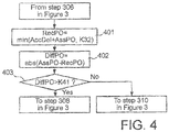
- FIG. 4 illustrates a detail example of the event-driven signaling procedure.
- DiffPO represents a difference of the power offsets
- K41 is a threshold for the power offset reporting.
- the base station calculates a difference between the calculated power offset and the assigned power offset, at step 402. If the difference is greater than a predefined reporting threshold, base station 20 sends the calculated power offset to radio network controller 30, at step 403. log 10 PO RNC ⁇ PO REC > PO REPTH where PO RNC and PO REC are the current and required power offsets respectively while PO REPTH is a threshold for the power offset reporting.
- the predefined reporting threshold can be signaled from the radio network controller to the base station.
- the radio network controller can have reporting from a base station on the required power offset of the EUDCH data flow. From this recommendation from the base station, the radio network controller can decide a new power offset of the EUDCH data flow. A detail procedure of the radio network controller assigning the new power offset is described in what follows:
- the radio network controller is utilizing priority and delay sensitivity of data flow when it decides to increase the required power offset.
- the benefit associated with this procedure is that limited total radio resource is prioritized to serve the high priority flow or delay sensitive flow rather than the low priority best-effort flow.
- the radio network controller accepts the required power offset only from the responsible base station.
- the benefit of this procedure is to minimize the required power offset by selecting the best quality base station hence increasing capacity of the uplink packet transmission.
- FIG. 6 illustrates another possible realization of the system according to the present invention. This illustrated system is an extension of the previous realization of system shown in Figure 2 . The difference between two systems are explained in the following:
- mobile station 10 shown in Figure 6 is provided with two EUDCH data transmitters (EDCH1 Tx, EDCH2 Tx) 601, 602 and time multiplexer (SW) 604 for two data flows.
- the base station is provided with two power offset estimators (POE1, POE2) 607, 608.
- Separate power offsets for two EUDCH data flows are used in power offset controller 603 for a DCH data flow and two EUDCH data flows.
- the separate power offsets are used in order to control the target error rate of each EUDCH data flow separately. Hence controlling separate QoS of each EUDCH data flow is possible by use of the separate power offset for each flow.
- Time multiplexing is used for transmitting two EUDCH data flows.
- the switching at time multiplexer 604 is performing selection for transmission from two data flows. For example, switching can perform round robin selection from between two data flows when both flows have sufficient data waiting for transmission, in order to separately control the target error rate of each data flow.
- base station 20 Based upon receiving the transmitted EUDCH data flow, base station 20 performs decoding of the EUDCH data flow at EUDCH decoder 606. Successfully decoded data is forwarded to RNC 30 and the reception status of the data flow is reported to power offset estimators 607, 608. As described above, there are two separate power offset estimators 607, 608 in the base station for each EUDCH data flow. Hence the reception status of the EUDCH data flow is updated to the corresponding power offset estimator only. For example, if the base station receives the first EUDCH data flow, the power offset estimator updating the power offset of the first EUDCH data flow will calculate new level of the required power offset using the reception status. The calculation is carried out by the same procedure illustrated in Figure 3 .
- Both base station 20 and mobile station 10 are controlling retransmission of data flow by a master controller, i.e., ARQ transmitter 605, and a slave controller, i.e., ARQ receiver 609.
- ARQ transmitter 605 functions as a retransmission master controller at the mobile station handling both EUDCH data flows
- ARQ receiver 609 functions as a retransmission slave controller at the base station handling both EUDCH data flows.
- retransmission information consists of the reception status and a corresponding data flow identification. The identification can be sent explicitly or it can be reduced implicitly from fixed timing between the uplink data transmission and the downlink control data transmission.
- the separate power offsets for two EUDCH data flows calculated by the base station are reported to RNC radio resource controller 610. Based on the reported power offset, RNC 30 makes decision on the power offset of each EUDCH data flow in a same way explained in Figure 5 . For example, if two EUDCH data flows have different priority and base station 20 reports a higher power offset for both data flows, then RNC can increase only the power offset of the higher priority data flow while rejecting that of the lower priority one. Then, RNC signals the newly assigned power offsets to the mobile station and base station(s).
Applications Claiming Priority (3)
| Application Number | Priority Date | Filing Date | Title |
|---|---|---|---|
| JP2004179831 | 2004-06-17 | ||
| EP20050750921 EP1758275B1 (de) | 2004-06-17 | 2005-06-03 | Aufwärtsstreckenleitungspaketdaten-sendeleistungssteuerverfahren |
| EP14163498.0A EP2753007B1 (de) | 2004-06-17 | 2005-06-03 | Verfahren zur Sendeleistungsregelung van Aufwärtsstreckenleitungspaketdaten |
Related Parent Applications (3)
| Application Number | Title | Priority Date | Filing Date |
|---|---|---|---|
| EP14163498.0A Division EP2753007B1 (de) | 2004-06-17 | 2005-06-03 | Verfahren zur Sendeleistungsregelung van Aufwärtsstreckenleitungspaketdaten |
| EP14163498.0A Division-Into EP2753007B1 (de) | 2004-06-17 | 2005-06-03 | Verfahren zur Sendeleistungsregelung van Aufwärtsstreckenleitungspaketdaten |
| EP20050750921 Division EP1758275B1 (de) | 2004-06-17 | 2005-06-03 | Aufwärtsstreckenleitungspaketdaten-sendeleistungssteuerverfahren |
Publications (2)
| Publication Number | Publication Date |
|---|---|
| EP3249828A1 true EP3249828A1 (de) | 2017-11-29 |
| EP3249828B1 EP3249828B1 (de) | 2018-04-25 |
Family
ID=35510080
Family Applications (4)
| Application Number | Title | Priority Date | Filing Date |
|---|---|---|---|
| EP14163498.0A Active EP2753007B1 (de) | 2004-06-17 | 2005-06-03 | Verfahren zur Sendeleistungsregelung van Aufwärtsstreckenleitungspaketdaten |
| EP20050750921 Active EP1758275B1 (de) | 2004-06-17 | 2005-06-03 | Aufwärtsstreckenleitungspaketdaten-sendeleistungssteuerverfahren |
| EP17175899.8A Active EP3249828B1 (de) | 2004-06-17 | 2005-06-03 | Übertragungsleistungssteuerungsverfahren für eine uplink-paketdatenübertragung |
| EP20080101313 Active EP1914908B1 (de) | 2004-06-17 | 2005-06-03 | Verfahren und System zur Sendeleistungsregelung für Paketdatenübertragung in der Aufwärtsrichtung |
Family Applications Before (2)
| Application Number | Title | Priority Date | Filing Date |
|---|---|---|---|
| EP14163498.0A Active EP2753007B1 (de) | 2004-06-17 | 2005-06-03 | Verfahren zur Sendeleistungsregelung van Aufwärtsstreckenleitungspaketdaten |
| EP20050750921 Active EP1758275B1 (de) | 2004-06-17 | 2005-06-03 | Aufwärtsstreckenleitungspaketdaten-sendeleistungssteuerverfahren |
Family Applications After (1)
| Application Number | Title | Priority Date | Filing Date |
|---|---|---|---|
| EP20080101313 Active EP1914908B1 (de) | 2004-06-17 | 2005-06-03 | Verfahren und System zur Sendeleistungsregelung für Paketdatenübertragung in der Aufwärtsrichtung |
Country Status (6)
| Country | Link |
|---|---|
| US (4) | US7613474B2 (de) |
| EP (4) | EP2753007B1 (de) |
| JP (2) | JP4683230B2 (de) |
| KR (2) | KR100921272B1 (de) |
| CN (3) | CN1969481B (de) |
| WO (1) | WO2005125048A1 (de) |
Families Citing this family (33)
| Publication number | Priority date | Publication date | Assignee | Title |
|---|---|---|---|---|
| CN1969481B (zh) * | 2004-06-17 | 2015-02-11 | 日本电气株式会社 | 上行链路分组数据发送功率控制方法 |
| US7688723B1 (en) * | 2004-09-16 | 2010-03-30 | Avaya Inc. | Procedural XML-based telephony traffic flow analysis and configuration tool |
| US7830813B1 (en) | 2004-09-30 | 2010-11-09 | Avaya Inc. | Traffic based availability analysis |
| JP4592547B2 (ja) * | 2005-08-24 | 2010-12-01 | 株式会社エヌ・ティ・ティ・ドコモ | 送信電力制御方法及び移動通信システム |
| JP4592545B2 (ja) * | 2005-08-24 | 2010-12-01 | 株式会社エヌ・ティ・ティ・ドコモ | 送信電力制御方法及び移動通信システム |
| JP4592548B2 (ja) * | 2005-08-24 | 2010-12-01 | 株式会社エヌ・ティ・ティ・ドコモ | 送信電力制御方法及び移動通信システム |
| JP4592546B2 (ja) * | 2005-08-24 | 2010-12-01 | 株式会社エヌ・ティ・ティ・ドコモ | 送信電力制御方法及び無線回線制御局 |
| JP4589249B2 (ja) * | 2006-02-21 | 2010-12-01 | 富士通株式会社 | 無線通信システムにおける電力制御装置 |
| KR100964577B1 (ko) * | 2006-06-02 | 2010-06-21 | 삼성전자주식회사 | 통신 시스템에서 전력 제어 방법 및 시스템 |
| CA2810296C (en) | 2006-06-13 | 2016-08-23 | Qualcomm Incorporated | Power control for wireless communication systems |
| KR100876715B1 (ko) * | 2006-08-24 | 2008-12-31 | 삼성전자주식회사 | 통신 시스템에서 역방향 전력 제어 방법 및 장치 |
| WO2008051625A2 (en) * | 2006-10-24 | 2008-05-02 | Cisco Technology, Inc. | Collaborative beam forming of base transceiver stations for reducing interference in a wireless multi-cell network |
| JP5014820B2 (ja) * | 2007-01-09 | 2012-08-29 | 株式会社エヌ・ティ・ティ・ドコモ | 移動通信システム、ユーザ装置及び通信方法 |
| KR101757173B1 (ko) | 2007-08-13 | 2017-07-12 | 알카텔-루센트 유에스에이 인코포레이티드 | 영속적인 스케줄링을 갖는 제어 채널 송신을 위한 방법 |
| KR20090056836A (ko) * | 2007-11-30 | 2009-06-03 | 포스데이타 주식회사 | 무선 통신 시스템에서 mcbcs와 매크로 다이버시티를 위한 mcbcs 프락시 선정을 지원하는 장치 및 방법 |
| CN101540628B (zh) * | 2008-03-21 | 2013-12-18 | 电信科学技术研究院 | 一种确定功率偏移参数的方法、系统和装置 |
| WO2009155003A2 (en) * | 2008-05-27 | 2009-12-23 | Viasat, Inc. | Return link power control |
| JP5293199B2 (ja) * | 2009-01-08 | 2013-09-18 | 富士通株式会社 | 無線通信装置、制御装置、移動通信システムおよび無線通信方法 |
| JP5373055B2 (ja) * | 2009-03-10 | 2013-12-18 | シャープ株式会社 | 移動局装置、通信システム、通信方法及びプログラム |
| JP4598866B2 (ja) * | 2009-03-12 | 2010-12-15 | 株式会社エヌ・ティ・ティ・ドコモ | 送信電力制御方法及び移動通信システム |
| EP2400801B1 (de) | 2009-03-16 | 2015-08-19 | Huawei Technologies Co., Ltd. | Verfahren, geräte und netzwerkeinrichtung zum regeln von leistung |
| CN104244389B (zh) * | 2009-03-16 | 2018-01-19 | 华为技术有限公司 | 一种功率控制方法、装置及网络设备 |
| US8873485B2 (en) * | 2009-06-17 | 2014-10-28 | Sharp Kabushiki Kaisha | Mobile station apparatus, base station apparatus, communication system, communication method and control program |
| US20110217969A1 (en) * | 2010-03-05 | 2011-09-08 | Qualcomm, Incorporated | Devices with multiple subscriptions that utilize a single baseband-radio frequency resource chain |
| WO2011132262A1 (ja) * | 2010-04-20 | 2011-10-27 | 富士通株式会社 | 送信装置、受信装置、無線通信システムおよび無線通信方法 |
| US9148858B2 (en) | 2010-07-12 | 2015-09-29 | Samsung Electronics Co., Ltd. | Apparatus and method for controlling uplink transmission power in a mobile communication system |
| KR20120006259A (ko) * | 2010-07-12 | 2012-01-18 | 삼성전자주식회사 | 이동 통신 시스템에서 업링크 송신 전력 상태 보고 장치 및 방법 |
| WO2014025208A1 (en) * | 2012-08-08 | 2014-02-13 | Samsung Electronics Co., Ltd. | A method and apparatus of bearer grouping for data transmission in a broadband wireless network |
| EP2885948B1 (de) * | 2012-08-15 | 2018-02-14 | Telefonaktiebolaget LM Ericsson (publ) | Systeme und verfahren zur bestimmung des messleistungsversatzes |
| US10624039B2 (en) | 2015-08-28 | 2020-04-14 | Huawei Technologies Co., Ltd. | System and method for power offset adjustments for downlink communications |
| CN110474719B (zh) * | 2018-05-11 | 2021-10-22 | 华为技术有限公司 | 一种重复传输的方法和装置 |
| CN113041871A (zh) * | 2021-04-22 | 2021-06-29 | 昆明有色冶金设计研究院股份公司 | 一种免搅拌多相混合分配装置 |
| KR20240025478A (ko) | 2022-08-18 | 2024-02-27 | 오렌지정보통신(주) | 인체연속감지장치 및 그의 제어방법 |
Citations (3)
| Publication number | Priority date | Publication date | Assignee | Title |
|---|---|---|---|---|
| US20030039217A1 (en) * | 2001-08-25 | 2003-02-27 | Samsung Electronics Co., Ltd. | Apparatus and method for transmitting/receiving uplink transmission power offset and HS-DSCH power level in a communication system employing HSDPA |
| WO2004034656A2 (en) * | 2002-10-07 | 2004-04-22 | Golden Bridge Technology, Inc. | Enhanced uplink packet transfer |
| WO2004042954A1 (en) * | 2002-10-30 | 2004-05-21 | Motorola, Inc., A Corporation Of The State Of Delaware | Method and apparatus for providing a distributed architecture digital wireless communication system |
Family Cites Families (32)
| Publication number | Priority date | Publication date | Assignee | Title |
|---|---|---|---|---|
| KR100288840B1 (ko) * | 1999-03-04 | 2001-04-16 | 박종섭 | 무선가입자망 시스템에서 가입자 정합장치 및 다중/단일 모드 제어방법 |
| US6317435B1 (en) * | 1999-03-08 | 2001-11-13 | Qualcomm Incorporated | Method and apparatus for maximizing the use of available capacity in a communication system |
| DE69901439D1 (de) | 1999-07-07 | 2002-06-13 | Alcatel Sa | Zellulares Telekommunikationssystem mit Makrodiversitätmodus |
| US6823193B1 (en) * | 2000-02-28 | 2004-11-23 | Telefonaktiebolaget Lm Ericsson (Publ) | Downlink transmit power synchronization during diversity communication with a mobile station |
| EP1177646B1 (de) * | 2000-03-10 | 2009-02-25 | Samsung Electronics Co., Ltd. | Verfahren zur durchführung einer weiterleitung in einem drahtlosen kommunikationssystem |
| JP3449340B2 (ja) | 2000-06-09 | 2003-09-22 | 日本電気株式会社 | Cdma移動通信システム及びそのソフトハンドオフ処理方法 |
| JP2001358651A (ja) | 2000-06-16 | 2001-12-26 | Yrp Mobile Telecommunications Key Tech Res Lab Co Ltd | 移動通信システム、基地局装置および送信電力制御方法 |
| US6650905B1 (en) * | 2000-06-30 | 2003-11-18 | Nokia Mobile Phones, Ltd. | Universal mobile telecommunications system (UMTS) terrestrial radio access (UTRA) frequency division duplex (FDD) downlink shared channel (DSCH) power control in soft handover |
| EP1232585A4 (de) * | 2000-10-04 | 2006-11-29 | Samsung Electronics Co Ltd | Vorrichtung und verfahren zur leistungsregelung eines gemeinsamen kanals in abwärtsrichtung in einem mobilen kommunikationssystem |
| KR100735402B1 (ko) * | 2000-11-07 | 2007-07-04 | 삼성전자주식회사 | 비동기 이동통신시스템에서 하향 공유 채널에 사용하는 송신 형식 결합 지시기의 전송 장치 및 방법 |
| US7010318B2 (en) * | 2001-01-13 | 2006-03-07 | Samsung Electronics Co., Ltd. | Power control apparatus and method for a W-CDMA communication system employing a high-speed downlink packet access scheme |
| US6757542B2 (en) * | 2001-09-27 | 2004-06-29 | Telefonaktiebolaget Lm Ericsson | Total radio network solution for GSM/EDGE |
| US7266103B2 (en) * | 2001-10-25 | 2007-09-04 | Qualcomm Incorporated | Controlling forward link traffic channel power |
| EP1313232B1 (de) * | 2001-11-19 | 2004-08-25 | Samsung Electronics Co., Ltd. | Verfahren und Vorrichtung für die Leistungsregelung des Aufwärtskanals in einem CDMA Kommunikationssystem |
| KR100832117B1 (ko) * | 2002-02-17 | 2008-05-27 | 삼성전자주식회사 | 고속 순방향 패킷 접속 방식을 사용하는 이동통신 시스템에서 역방향 송신전력 오프셋 정보를 송수신하는 장치 및 방법 |
| US7133688B2 (en) * | 2002-04-05 | 2006-11-07 | Lucent Technologies Inc. | Method for improving uplink control channel efficiency in a wireless communication system |
| CA2484725C (en) * | 2002-05-09 | 2011-09-13 | Nokia Corporation | Hsdpa cqi, ack, nack power offset known in node b and in srnc |
| KR100891816B1 (ko) * | 2002-05-11 | 2009-04-07 | 삼성전자주식회사 | 비동기 부호분할다중접속 이동통신시스템에서 고속 순방향 물리공유채널의 전력 오프셋 정보 전송 방법 |
| JP4074476B2 (ja) | 2002-05-23 | 2008-04-09 | 株式会社エヌ・ティ・ティ・ドコモ | ソフトハンドオーバー時における送信電力制御方法および無線制御装置 |
| JP2004032640A (ja) * | 2002-06-28 | 2004-01-29 | Matsushita Electric Ind Co Ltd | 送信電力制御方法、通信端末装置及び基地局装置 |
| JP4022106B2 (ja) | 2002-06-28 | 2007-12-12 | 松下電器産業株式会社 | シグナリング方法及び基地局装置 |
| JP2004064142A (ja) | 2002-07-24 | 2004-02-26 | Ntt Docomo Inc | 送信電力制御方法、これに用いて好適な無線通信システム、無線基地局及び移動局 |
| JP2004080235A (ja) * | 2002-08-14 | 2004-03-11 | Nec Corp | セルラシステム、移動局、基地局及びそれに用いる送信電力制御方法並びにそのプログラム |
| JP3796212B2 (ja) * | 2002-11-20 | 2006-07-12 | 松下電器産業株式会社 | 基地局装置及び送信割り当て制御方法 |
| US7505780B2 (en) * | 2003-02-18 | 2009-03-17 | Qualcomm Incorporated | Outer-loop power control for wireless communication systems |
| JP4288093B2 (ja) * | 2003-04-09 | 2009-07-01 | 株式会社エヌ・ティ・ティ・ドコモ | 無線通信制御システム及び無線通信制御方法 |
| US7369501B2 (en) * | 2003-04-29 | 2008-05-06 | Lg Electronics Inc. | Apparatus and method for controlling reverse-link data transmission rate during handoff |
| US7321780B2 (en) * | 2003-04-30 | 2008-01-22 | Motorola, Inc. | Enhanced uplink rate selection by a communication device during soft handoff |
| WO2005050900A1 (de) * | 2003-11-17 | 2005-06-02 | Siemens Aktiengesellschaft | Verfahren zur übertragung von datenpaketen |
| US8243633B2 (en) * | 2004-03-16 | 2012-08-14 | Nokia Corporation | Enhanced uplink dedicated channel—application protocol over lub/lur |
| US7983708B2 (en) * | 2004-04-28 | 2011-07-19 | Airvana Network Solutions, Inc. | Reverse link power control |
| CN1969481B (zh) * | 2004-06-17 | 2015-02-11 | 日本电气株式会社 | 上行链路分组数据发送功率控制方法 |
-
2005
- 2005-06-03 CN CN200580019936.8A patent/CN1969481B/zh active Active
- 2005-06-03 KR KR20067017895A patent/KR100921272B1/ko active IP Right Grant
- 2005-06-03 EP EP14163498.0A patent/EP2753007B1/de active Active
- 2005-06-03 JP JP2006514688A patent/JP4683230B2/ja active Active
- 2005-06-03 EP EP20050750921 patent/EP1758275B1/de active Active
- 2005-06-03 US US10/591,813 patent/US7613474B2/en active Active
- 2005-06-03 EP EP17175899.8A patent/EP3249828B1/de active Active
- 2005-06-03 WO PCT/JP2005/010249 patent/WO2005125048A1/ja not_active Application Discontinuation
- 2005-06-03 CN CN2008100001776A patent/CN101202575B/zh active Active
- 2005-06-03 KR KR1020087020933A patent/KR100953782B1/ko active IP Right Grant
- 2005-06-03 CN CN201110438023.7A patent/CN102573031B/zh active Active
- 2005-06-03 EP EP20080101313 patent/EP1914908B1/de active Active
-
2009
- 2009-08-26 US US12/548,009 patent/US7962167B2/en active Active
- 2009-09-03 US US12/553,461 patent/US8107992B2/en active Active
-
2010
- 2010-11-11 JP JP2010252792A patent/JP4735908B2/ja active Active
-
2011
- 2011-12-09 US US13/315,854 patent/US8423074B2/en active Active
Patent Citations (3)
| Publication number | Priority date | Publication date | Assignee | Title |
|---|---|---|---|---|
| US20030039217A1 (en) * | 2001-08-25 | 2003-02-27 | Samsung Electronics Co., Ltd. | Apparatus and method for transmitting/receiving uplink transmission power offset and HS-DSCH power level in a communication system employing HSDPA |
| WO2004034656A2 (en) * | 2002-10-07 | 2004-04-22 | Golden Bridge Technology, Inc. | Enhanced uplink packet transfer |
| WO2004042954A1 (en) * | 2002-10-30 | 2004-05-21 | Motorola, Inc., A Corporation Of The State Of Delaware | Method and apparatus for providing a distributed architecture digital wireless communication system |
Non-Patent Citations (6)
| Title |
|---|
| "Technical Report 3rd Generation Partnership Project", 3GPP TR 25.896 V1.2.1, January 2004 (2004-01-01) |
| "Technical Report 3rd Generation Partnership Project", 3GPP TS 25.214 V5.6.0, September 2003 (2003-09-01) |
| "Technical Report of 3GPP", 3GPP TR 25.896 V1.2.1, January 2004 (2004-01-01) |
| "Technical Report of 3GPP", 3GPP TS 25.214 V5.6.0, September 2003 (2003-09-01) |
| 3GPP TR 25,896 V1.2.1, January 2004 (2004-01-01) |
| 3GPP TS 25.214 V5.6.0, September 2003 (2003-09-01) |
Also Published As
| Publication number | Publication date |
|---|---|
| CN101202575B (zh) | 2012-02-01 |
| KR20070018870A (ko) | 2007-02-14 |
| EP1758275B1 (de) | 2014-08-13 |
| EP1914908A3 (de) | 2008-05-07 |
| US8423074B2 (en) | 2013-04-16 |
| JP4683230B2 (ja) | 2011-05-18 |
| EP1914908B1 (de) | 2014-01-22 |
| EP2753007B1 (de) | 2017-07-26 |
| EP3249828B1 (de) | 2018-04-25 |
| KR100953782B1 (ko) | 2010-04-21 |
| US8107992B2 (en) | 2012-01-31 |
| CN102573031A (zh) | 2012-07-11 |
| EP2753007A1 (de) | 2014-07-09 |
| US20090325627A1 (en) | 2009-12-31 |
| EP1758275A4 (de) | 2008-05-07 |
| KR100921272B1 (ko) | 2009-10-09 |
| CN1969481A (zh) | 2007-05-23 |
| US7962167B2 (en) | 2011-06-14 |
| JP2011066927A (ja) | 2011-03-31 |
| JPWO2005125048A1 (ja) | 2008-04-17 |
| CN102573031B (zh) | 2015-10-21 |
| WO2005125048A1 (ja) | 2005-12-29 |
| CN101202575A (zh) | 2008-06-18 |
| EP1914908A2 (de) | 2008-04-23 |
| EP1758275A1 (de) | 2007-02-28 |
| JP4735908B2 (ja) | 2011-07-27 |
| CN1969481B (zh) | 2015-02-11 |
| US20120076066A1 (en) | 2012-03-29 |
| US20090316663A1 (en) | 2009-12-24 |
| KR20080089514A (ko) | 2008-10-06 |
| US20070189230A1 (en) | 2007-08-16 |
| US7613474B2 (en) | 2009-11-03 |
Similar Documents
| Publication | Publication Date | Title |
|---|---|---|
| EP2753007B1 (de) | Verfahren zur Sendeleistungsregelung van Aufwärtsstreckenleitungspaketdaten | |
| US11672020B2 (en) | Wireless communication system and method of controlling a transmission power | |
| EP1223769B1 (de) | Verfahren und Vorrichtung zur Leistungssteuerung für ein WCDMA Kommunikationssystem, dass ein Hochgeschwindigkeitabwärtsrichtungspaketzugriffverfahren verwendet | |
| US7801547B2 (en) | System and method for determining downlink signaling power in a radio communication network | |
| US8526357B2 (en) | Methods and arrangements for handling unreliable scheduling grants in a telecommunication network | |
| EP1346594B1 (de) | Verfahren und vorrichtung zur verbindungswiederherstellung in einem drahtlosen kommunikationssystem | |
| US20060079264A1 (en) | Outer loop power control of user equipment in wireless communication | |
| US20020068569A1 (en) | Method and apparatus for flexible call recovery in a wireless communication system | |
| JP4927741B2 (ja) | 電気通信システムにおける方法および装置 | |
| US20080070583A1 (en) | Method and apparatus for setting serving grant in a wireless communications system | |
| CN104854798A (zh) | 用于无线网络中的功率控制的系统和方法 | |
| WO2006040632A1 (en) | Outer loop power control of user equipment in wireless communication | |
| WO2010020113A1 (zh) | 控制信道的功率控制方法及装置 |
Legal Events
| Date | Code | Title | Description |
|---|---|---|---|
| PUAI | Public reference made under article 153(3) epc to a published international application that has entered the european phase |
Free format text: ORIGINAL CODE: 0009012 |
|
| AC | Divisional application: reference to earlier application |
Ref document number: 1758275 Country of ref document: EP Kind code of ref document: P Ref document number: 2753007 Country of ref document: EP Kind code of ref document: P |
|
| AK | Designated contracting states |
Kind code of ref document: A1 Designated state(s): DE FR GB IT |
|
| GRAP | Despatch of communication of intention to grant a patent |
Free format text: ORIGINAL CODE: EPIDOSNIGR1 |
|
| 17P | Request for examination filed |
Effective date: 20171121 |
|
| RBV | Designated contracting states (corrected) |
Designated state(s): DE FR GB IT |
|
| INTG | Intention to grant announced |
Effective date: 20171219 |
|
| GRAS | Grant fee paid |
Free format text: ORIGINAL CODE: EPIDOSNIGR3 |
|
| GRAA | (expected) grant |
Free format text: ORIGINAL CODE: 0009210 |
|
| AC | Divisional application: reference to earlier application |
Ref document number: 1758275 Country of ref document: EP Kind code of ref document: P Ref document number: 2753007 Country of ref document: EP Kind code of ref document: P |
|
| AK | Designated contracting states |
Kind code of ref document: B1 Designated state(s): DE FR GB IT |
|
| REG | Reference to a national code |
Ref country code: GB Ref legal event code: FG4D |
|
| REG | Reference to a national code |
Ref country code: FR Ref legal event code: PLFP Year of fee payment: 14 |
|
| REG | Reference to a national code |
Ref country code: DE Ref legal event code: R096 Ref document number: 602005053893 Country of ref document: DE |
|
| REG | Reference to a national code |
Ref country code: DE Ref legal event code: R097 Ref document number: 602005053893 Country of ref document: DE |
|
| PLBE | No opposition filed within time limit |
Free format text: ORIGINAL CODE: 0009261 |
|
| STAA | Information on the status of an ep patent application or granted ep patent |
Free format text: STATUS: NO OPPOSITION FILED WITHIN TIME LIMIT |
|
| 26N | No opposition filed |
Effective date: 20190128 |
|
| PGFP | Annual fee paid to national office [announced via postgrant information from national office to epo] |
Ref country code: FR Payment date: 20230628 Year of fee payment: 19 Ref country code: DE Payment date: 20230620 Year of fee payment: 19 |
|
| PGFP | Annual fee paid to national office [announced via postgrant information from national office to epo] |
Ref country code: IT Payment date: 20230623 Year of fee payment: 19 Ref country code: GB Payment date: 20230622 Year of fee payment: 19 |