EP3249677A2 - Miniaturionenpumpe - Google Patents
Miniaturionenpumpe Download PDFInfo
- Publication number
- EP3249677A2 EP3249677A2 EP17168240.4A EP17168240A EP3249677A2 EP 3249677 A2 EP3249677 A2 EP 3249677A2 EP 17168240 A EP17168240 A EP 17168240A EP 3249677 A2 EP3249677 A2 EP 3249677A2
- Authority
- EP
- European Patent Office
- Prior art keywords
- anode
- cathode
- magnet
- filament
- ion pump
- Prior art date
- Legal status (The legal status is an assumption and is not a legal conclusion. Google has not performed a legal analysis and makes no representation as to the accuracy of the status listed.)
- Granted
Links
Images


Classifications
-
- H—ELECTRICITY
- H01—ELECTRIC ELEMENTS
- H01J—ELECTRIC DISCHARGE TUBES OR DISCHARGE LAMPS
- H01J41/00—Discharge tubes for measuring pressure of introduced gas or for detecting presence of gas; Discharge tubes for evacuation by diffusion of ions
- H01J41/12—Discharge tubes for evacuating by diffusion of ions, e.g. ion pumps, getter ion pumps
- H01J41/14—Discharge tubes for evacuating by diffusion of ions, e.g. ion pumps, getter ion pumps with ionisation by means of thermionic cathodes
-
- F—MECHANICAL ENGINEERING; LIGHTING; HEATING; WEAPONS; BLASTING
- F04—POSITIVE - DISPLACEMENT MACHINES FOR LIQUIDS; PUMPS FOR LIQUIDS OR ELASTIC FLUIDS
- F04B—POSITIVE-DISPLACEMENT MACHINES FOR LIQUIDS; PUMPS
- F04B37/00—Pumps having pertinent characteristics not provided for in, or of interest apart from, groups F04B25/00 - F04B35/00
- F04B37/02—Pumps having pertinent characteristics not provided for in, or of interest apart from, groups F04B25/00 - F04B35/00 for evacuating by absorption or adsorption
- F04B37/04—Selection of specific absorption or adsorption materials
-
- F—MECHANICAL ENGINEERING; LIGHTING; HEATING; WEAPONS; BLASTING
- F04—POSITIVE - DISPLACEMENT MACHINES FOR LIQUIDS; PUMPS FOR LIQUIDS OR ELASTIC FLUIDS
- F04B—POSITIVE-DISPLACEMENT MACHINES FOR LIQUIDS; PUMPS
- F04B37/00—Pumps having pertinent characteristics not provided for in, or of interest apart from, groups F04B25/00 - F04B35/00
- F04B37/10—Pumps having pertinent characteristics not provided for in, or of interest apart from, groups F04B25/00 - F04B35/00 for special use
- F04B37/18—Pumps having pertinent characteristics not provided for in, or of interest apart from, groups F04B25/00 - F04B35/00 for special use for specific elastic fluids
Definitions
- Ion pumps are a workhorse of ultra-high vacuum systems. With no moving parts, they are quiet and consume very little electrical power. They are also very clean, containing only metal interior surfaces that capture and trap gas within the pump body. Ion pumps can be used to provide vacuum for numerous applications, including inertial sensors such as atomic interferometer-based accelerometers, gyroscopes and gravimeters, as well as time keeping devices such as atomic clocks. Reducing the volume of these sensors is desirable in order to deploy them on moving vehicles or other dynamic platforms. Often, the ion pump size is the limiting factor for total system volume. In addition, the magnetic fringe fields produced by the pump can impact the sensor.
- the invention can be implemented in numerous ways, including as a process; an apparatus; a system; a composition of matter; a computer program product embodied on a computer readable storage medium; and/or a processor, such as a processor configured to execute instructions stored on and/or provided by a memory coupled to the processor.
- these implementations, or any other form that the invention may take, may be referred to as techniques.
- the order of the steps of disclosed processes may be altered within the scope of the invention.
- a component such as a processor or a memory described as being configured to perform a task may be implemented as a general component that is temporarily configured to perform the task at a given time or a specific component that is manufactured to perform the task.
- the term 'processor' refers to one or more devices, circuits, and/or processing cores configured to process data, such as computer program instructions.
- the system for pumping comprises an anode; a cathode; and a magnet, wherein the magnet comprises a Halbach magnet.
- the system for pumping comprises an anode, a cathode, a filament, wherein the filament enters a region in the vicinity (e.g., within 1-2 millimeters) of the anode surface and the cathode surface, and a magnet.
- a miniature system for pumping comprises an ion pump.
- An ion pump comprises an anode, a cathode, and a magnet creating a magnetic field in the region between the anode surface and the cathode surface.
- the miniature system for pumping has a diameter D of the cylinder of the anode of less than 1 cm, has a diameter D of the cylinder of the anode of less than 0.8 cm, or any other appropriate small diameter.
- a high voltage power supply is connected between the anode and cathode in order to establish a potential difference between them. The combination of the high voltage and magnetic field causes stray electrons to collide with molecules within the pump volume. The collisions cause the molecules to ionize.
- Ionized molecules are then rapidly accelerated to the cathode by the electrical field produced by the high voltage.
- the anode is at a positive high voltage with respect to the cathode.
- the anode is at a negative high voltage with respect to the cathode.
- the ion pump removes molecules from the pump volume in this way, gradually lowering the pressure.
- the miniature system for pumping comprises an ion pump designed to be placed in close proximity with other high sensitivity equipment. Therefore, minimizing the fringing fields of the magnet so as not to disturb the other equipment is a priority.
- the magnet of the ion pump comprises a Halbach magnet or Halbach magnet array, which comprises an array of magnets in a configuration that reduces fringing fields.
- the Halbach magnet creates a magnetic field within its roughly cylindrical shape with reduced fringing fields.
- the miniature system for pumping comprises an anode and a cathode designed to fit within the roughly cylindrical shape of the Halbach magnet.
- ionization within an ion pump starts as a result of the random emission of an electron from the cathode.
- a random emission occurs within a short time as the number of potential sources for the emission are large.
- the expected time for emission of an electron can be undesirably large.
- the pump in order to start ionization directly, the pump comprises an auxiliary electron emission source.
- This source may be a filament, field emitter or similar means. In the case of a filament, it enters into the vicinity (e.g., within 1-2 millimeters) of the surface of the anode and the surface of the cathode.
- Power is provided to the filament, causing it to heat and emit electrons, which are then able to start ionization of the pump.
- the pump current e.g., the current drawn from the high voltage power supply
- the filament is able to start ionization with enough reliability that feedback is not required, and a predetermined pulse shape of power is applied to the filament.
- FIG. 1 is a diagram illustrating an embodiment of an ion pump.
- the ion pump comprises anode 100 and cathode 102.
- the anode has a cylindrical shape with height h and diameter D, and the cathode comprises a plate at either end of the anode cylinder.
- a power supply is used to raise the anode to high voltage (e.g., 3 - 7 kV) relative to the cathode (e.g., at ground).
- a magnet is used to create a magnetic field parallel to the axis of the anode cylinder.
- the pumping speed increases quadratically with the magnetic field B for large enough fields and pressures below 10 -5 Torr (medium to high vacuum) operation.
- B crit 600 gauss / D, where D is in centimeters.
- FIG 2A is a diagram illustrating an embodiment of a dipole magnet.
- dipole magnet 200 is used to create the magnetic field of the ion pump of Figure 1 .
- dipole magnet 200 comprises a pair of magnetic plates placed parallel to one another - for example, plate 202 above and plate 204 below the cathode plates of an ion pump with a soft-iron yoke 206 serving to return the magnetic flux.
- dipole magnet 200 has high fringing fields.
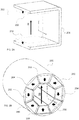
- FIG. 2B is a diagram illustrating an embodiment of a Halbach magnet array.
- Halbach magnet array 250 is used to create the magnetic field of the ion pump of Figure 1 .
- Halbach magnet array 250 comprises eight magnetic regions (e.g., magnet 252, magnet 254, magnet 256, magnet 258, magnet 260, magnet 262, magnet 264, and magnet 266), each the shape of an extruded trapezoid.
- the eight regions are arranged around a central axis to form the shape of an extruded octagon with a central cavity the shape of a smaller extruded octagon.
- the eight magnets taken together comprise a different shape such as an extruded annulus, a different numbers of magnets are used, or any other appropriate variation of magnet configurations.
- the ion pump is placed within the central cavity of Halbach magnet array 250.
- Halbach magnet array 250 has reduced fringing fields (e.g., as compared with dipole magnet 200).
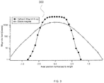
- FIG 3 is a diagram illustrating an embodiment of magnetic field measurement data.
- graph 300 comprises magnetic field data taken from a dipole magnet (e.g., dipole magnet 200 of Figure 2A ) and from a Halbach magnet (e.g., Halbach magnet 250 of Figure 2B ).
- both magnets are of length 1 (e.g., they extend from -0.5 to 0.5 in the graph). It is observed that outside the magnet (e.g., below -0.5 or above 0.5) the magnetic field strength drops off faster for the Halbach magnet than the dipole magnet, while within the magnet (e.g., above -0.5 and below 0.5) the magnetic field strength is higher for the Halbach magnet.
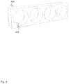
- FIG 4 is a diagram illustrating an embodiment of an anode.
- anode 400 comprises anode 100 of Figure 1 .
- anode 400 comprises a plurality of anode chambers (e.g., anode chamber 402).
- the anode chambers are cylindrical.
- anode 400 comprises 4 anode chambers.
- anode 400 comprises 1, 2, 3, 4, 5, 6, 7, 8, 9, 10, 11, 22, 48, or any other appropriate number of anode chambers.
- anode 400 is formed from titanium, stainless steel, tungsten, aluminum, molybdenum, or any other appropriate material.
- the cylinders are 5 mm in diameter and 5 mm in depth and there is a 0.5 mm gap between cylinders.
- FIG. 5 is a diagram illustrating an embodiment of an anode comprising a filament.
- anode 500 comprises anode chamber 502 and filament 504.
- Filament 504 extends from outside anode 500, through hole 506, and into anode chamber 502.
- filament 504 comprises a filament for starting an ion pump.
- applying power to filament 504 e.g., by connecting a power supply to filament end 508 and filament end 510) causes filament 504 to emit electrons. This starts the ionization of the ion pump.
- the cylinders of the anode are 5 mm diameter each, and the filament is approximately 3.5 mm from the base to the tip.
- the detailed shape of the filament is not critical, but the shown shape works well.
- FIG. 6 is a diagram illustrating an embodiment of an anode and a cathode.
- anode 600 comprises filament 604.
- Anode 600 is partially inserted into cathode 602.
- cathode 602 comprises cathode 102 of Figure 1 .
- anode 600 slides into cathode 602.
- cathode 602 comprises a cylinder.
- cathode 602 is formed from titanium, tantalum, or other reactive material.
- the anode is insulated from the cathode via a ceramic standoff.
- the cathode inner diameter (ID) is 7.5 mm and its length is 38.5 mm.
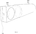
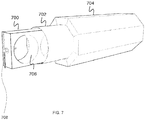
- Figure 7 is a diagram illustrating an embodiment of an anode, a cathode, and a Halbach magnet.
- anode 700 comprises filament 708.
- Anode 700 is partially inserted into cathode 702 and cathode 702 is partially inserted into Halbach magnet 704.
- cathode 702 slides into Halbach magnet 704.
- anode 700 comprises a plurality of cylindrical anode chambers (e.g., anode chamber 706).
- Halbach magnet 704 is oriented such that the magnetic field within its central cavity is oriented parallel or substantially parallel (e.g., within 5 degree) to the central axis of the anode chambers.
- index markings are used to align Halbach magnet 704 with cathode 702.
- index markings are used to align cathode 702 with anode 700 using the vacuum outer housing as a guide.
- anode 700 slides into cathode 702 in a fixed orientation (e.g., there is only one way to fit anode 700 into cathode 702, due to a groove, a flange, etc.).
- the orientation of cathode 702 within Halbach magnet 704 is adjustable (e.g., to allow the orientation to be manually tuned).
- the orientation of cathode 702 within Halbach magnet 704 is lockable (e.g., to fix the orientation once it is tuned to the correct orientation). In some embodiments, the orientation of cathode 702 is lockable using a set screw to fix the orientation.
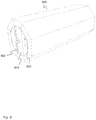
- FIG 8 is a diagram illustrating an embodiment of an ion pump assembly.
- anode 800 is inserted into cathode 802 and cathode 802 is inserted into Halbach magnet 804.
- cathode 802 is cylindrical.
- cathode 802 shape avoids sharp corners that can break down the high voltage difference between cathode 802 and anode 800.
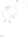
- FIG 9 is a diagram illustrating an embodiment of an ion pump assembly comprising a filament.
- ion pump assembly 900 comprises the ion pump assembly of Figure 8 .
- Ion pump assembly 900 additionally comprises filament 902.
- filament 902 enters a region between or in the vicinity (e.g., within 1-2 millimeters) of the surface of anode 904 and cathode 906.
- FIG 10 is a diagram illustrating an embodiment of an ion pump assembly comprising a cathode including a connection region.
- ion pump assembly 1000 comprises ion pump assembly 900 of Figure 9 .
- a cathode extends out from a Halbach magnet, including cathode pump region 1002 and cathode connection region 1006.
- Cathode pump region 1002 and cathode connection region 1006 are separated by transition 1004.
- cathode pump region 1002 and cathode connection region 1006 are made from different materials.
- cathode pump region 1002 is made from titanium and cathode connection region 1006 is made from stainless steel.
- cathode connection region 1006 comprises mounting flange 1008, including a set of mounting holes (e.g., mounting hole 1010).
- mounting holes are used to bolt the ion pump assembly to other equipment (e.g., a vacuum chamber, a sensor, etc.).
- FIG. 11 is a block diagram illustrating an embodiment of ion pump power supply connections.
- an ion pump comprises anode 1100, cathode 1102 and filament 1104.
- High voltage power supply 1106 comprises a high voltage power supply for powering the ion pump.
- the positive terminal of high voltage power supply 1006 is connected to anode 1100 and the negative terminal of high voltage power supply 1006 is connected to cathode 1102.
- Filament power supply 1108 comprises a filament power supply for heating filament 1104.
- the positive and negative terminals of filament power supply 1108 are connected to opposite ends of filament 1104.
- Controller 1110 comprises a controller for providing control information to and receiving measurements from high voltage power supply 1106 and filament 1108.
- control information comprises an on/off signal, a voltage setting, a current limit, or any other appropriate control information.
- measurements comprise voltage measurements, current measurements, or any other appropriate measurements.
- controller 1110 provides an indication to high voltage power supply 1106 to turn on to high voltage and an indication to filament power supply 1108 to turn on to an appropriate filament voltage (e.g., 1 V, 3 V, 10 V, etc.).
- controller 1110 measures current drawn from high voltage power supply 1106 above a threshold current (e.g., indicating that the pump has started), controller 1110 provides an indication to filament power supply 1108 to turn off.
- controller 1110 provides an indication to high voltage power supply 1106 to turn on to high voltage and an indication to filament power supply 1108 to pulse according to a predetermined pulse shape (e.g., the voltage turns on for a predetermined period of time and then turns off; the voltage ramps up at a predetermined rate, stays on for a predetermined period of time, and then ramps down at a predetermined rate, etc.).
- a predetermined pulse shape e.g., the voltage turns on for a predetermined period of time and then turns off; the voltage ramps up at a predetermined rate, stays on for a predetermined period of time, and then ramps down at a predetermined rate, etc.
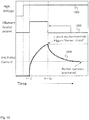
- Figure 12 is a diagram illustrating an embodiment of a startup process for an ion pump.
- the diagram of Figure 12 comprises a set of voltage and current measurements for the ion pump power supply connections shown in Figure 11 .
- high voltage measurement 1200 comprises an indication of the high voltage output of a high voltage power supply (e.g., high voltage power supply 1106 of Figure 11 ).
- Filament heater power measurement 1202 comprises an indication of the voltage output of a filament power supply (e.g., filament power supply 1108 of Figure 11 ).
- Ion pump current measurement 1204 comprises an indication of the current drawn by the ion pump (e.g., from the high voltage power supply). In the example shown, the high voltage is turned on first.
- the ion pump When the threshold current is reached, the ion pump is determined to be properly started up, and the filament heater power is shut off. The current then falls in the shape of a decaying exponential, until the steady-state operational current of the ion pump is reached. In some embodiments, a typical value of the steady-state operational current of the ion pump is 1 microAmp.
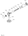
- Figure 13 is a diagram illustrating an embodiment of a miniature ion pump assembly.
- the diagram of Figure 13 comprises an exploded view of a miniature ion pump assembly.
- weld cap 1300 comprises a weld cap for sealing the ion pump assembly by sealing the end opening of ion pump housing 1304.
- Brazed filament assembly 1302 comprises a filament assembly for starting the pump by thermionic emission.
- Ion pump housing 1304 comprises a housing for containing the pump assembly.
- Electrical feedthrough 1306 comprises a feedthrough for providing electrical contact to the filament.
- Titanium / stainless steel bimetal tube assembly 1308 comprises a tube assembly for providing a titanium cathode and a stainless steel mounting connection.
- titanium / stainless steel bimetal tube assembly 1308 is fabricated using explosive bonding.
- Penning cell 1310 comprises an ion pump anode.
- High voltage connector 1312 comprises a high voltage connector for connecting Penning cell 1310 to a high voltage power supply.
- Magnet spacer 1314 comprises a magnet spacer for positioning a magnet relative to Penning cell 1310.
- Hallbach magnet 1316 comprises a Hallbach magnet for providing a magnetic field within the ion pump.
- Magnet clamp 1318 comprises a clamp for holding Hallbach magnet 1316.
- Pump port tube 1320 comprises a pump port tube for connecting the atmosphere of the ion pump to a piece of vacuum equipment.
- Pump conflat flange 1322 comprises a conflat flange for sealing the pump to a piece of vacuum equipment.
- Ion pump housing 1304 is attached to Halbach magnet 1316 by being pressed in place and held using magnetic clamp 1318. In some embodiments, from ion pump housing 1304 to magnetic clamp 1318 measures 50 mm. In some embodiments, electrical feedthrough 1306 connects to the filament only. In some embodiments, high voltage connector 1312 connects to both the anode and the cathode, and seals the pump. Magnetic spacer 1314, Halbach magnet 1316, and magnet clamp 1318 are outside the vacuum.
- Figure 14 is a flow diagram illustrating an embodiment of a process for ion pumping. In some embodiments, the process of Figure 14 is used to operate the ion pump of Figure 11 .
- an anode is provided in 1400 .
- a cathode is provided in 1402, a magnet is provided, wherein the magnet comprises a Halbach magnet.
- a voltage is provided between the anode and cathode. For example, a voltage between 3-7kV is provided between the anode and cathode.
- a hardware device and/or a computer program switches or indicates to switch on a voltage that is provided to the anode and cathode.
- 1406 is not performed unless an indication is received to start ion pumping.
- power is provided to the filament.
- the filament is provided power to start the ion current in the pump because the anode and/or cathode are small in surface area leading to a longer time for spontaneous starting of the pump.
- a hardware device and/or a computer program switches or indicates to switch on power that is provided to the filament.
- a hardware device and/or a computer program receives data regarding ion pump current - for example, a digital conversion of a signal that measures the ion pump current is received and the value associated with the digitized conversion of the signal is compared to a threshold value. In the event that the ion current is not above the threshold control passes to 1410. In the event that the ion current is above the threshold, in 1412 the filament power is removed. In 1414, it is determined whether an indication to stop pumping is received. In the event that an indication to stop pumping is not received, control passes to 1414. In the event that an indication to stop pumping is received, then in 1416 the voltage between the anode and the cathode is removed and the process ends.
- a hardware device and/or a computer program switches or indicates to switch off power that is provided to the anode and cathode.
- filament power is provided in the event that the pump current is not above threshold. In some embodiments, in the event that voltage is provided and current flows, the filament is not needed.
Landscapes
- Engineering & Computer Science (AREA)
- Mechanical Engineering (AREA)
- General Engineering & Computer Science (AREA)
- Electron Tubes For Measurement (AREA)
Applications Claiming Priority (1)
| Application Number | Priority Date | Filing Date | Title |
|---|---|---|---|
| US15/165,347 US10460917B2 (en) | 2016-05-26 | 2016-05-26 | Miniature ion pump |
Publications (3)
| Publication Number | Publication Date |
|---|---|
| EP3249677A2 true EP3249677A2 (de) | 2017-11-29 |
| EP3249677A3 EP3249677A3 (de) | 2018-03-07 |
| EP3249677B1 EP3249677B1 (de) | 2020-12-09 |
Family
ID=58664513
Family Applications (1)
| Application Number | Title | Priority Date | Filing Date |
|---|---|---|---|
| EP17168240.4A Active EP3249677B1 (de) | 2016-05-26 | 2017-04-26 | Miniaturionenpumpe |
Country Status (2)
| Country | Link |
|---|---|
| US (1) | US10460917B2 (de) |
| EP (1) | EP3249677B1 (de) |
Families Citing this family (2)
| Publication number | Priority date | Publication date | Assignee | Title |
|---|---|---|---|---|
| US10629417B1 (en) * | 2016-12-01 | 2020-04-21 | ColdQuanta, Inc. | Sputter ion pump with penning-trap current sensor |
| EP3652435A4 (de) * | 2017-07-11 | 2021-04-07 | McBride, Sterling Eduardo | Kompakte elektrostatische ionenpumpe |
Family Cites Families (27)
| Publication number | Priority date | Publication date | Assignee | Title |
|---|---|---|---|---|
| US2993638A (en) * | 1957-07-24 | 1961-07-25 | Varian Associates | Electrical vacuum pump apparatus and method |
| GB910607A (de) * | 1958-08-01 | |||
| US3228589A (en) * | 1963-10-16 | 1966-01-11 | Gen Electric | Ion pump having encapsulated internal magnet assemblies |
| CH442600A (de) * | 1966-05-18 | 1967-08-31 | Balzers Patent Beteilig Ag | Hochvakuumpumpe |
| US3540812A (en) | 1968-04-12 | 1970-11-17 | Rca Corp | Sputter ion pump |
| US3601503A (en) * | 1969-08-08 | 1971-08-24 | Thomas W Snouse | Thin membrane ionization pump apparatus |
| US3949260A (en) * | 1975-04-14 | 1976-04-06 | Hughes Aircraft Company | Continuous ionization injector for low pressure gas discharge device |
| JPS59123152A (ja) * | 1982-12-28 | 1984-07-16 | Hajime Ishimaru | イオンポンプ |
| JPS6351037A (ja) * | 1986-08-20 | 1988-03-04 | Toshiba Corp | 電子ビ−ム装置の陽極室 |
| US6004104A (en) * | 1997-07-14 | 1999-12-21 | Duniway Stockroom Corp. | Cathode structure for sputter ion pump |
| IT1307236B1 (it) * | 1999-04-02 | 2001-10-30 | Varian Spa | Pompa ionica. |
| CN1366706A (zh) * | 2000-03-13 | 2002-08-28 | 爱发科股份有限公司 | 离子溅射泵 |
| FR2835964B1 (fr) * | 2002-02-14 | 2004-07-09 | Centre Nat Rech Scient | Piege a ions a aimant permanent et spectrometre de masse utilisant un tel aimant |
| US20040062659A1 (en) * | 2002-07-12 | 2004-04-01 | Sinha Mahadeva P. | Ion pump with combined housing and cathode |
| US20040234379A1 (en) | 2003-05-22 | 2004-11-25 | Nanocoolers, Inc. | Direct current magnetohydrodynamic pump configurations |
| JP2006066265A (ja) | 2004-08-27 | 2006-03-09 | Canon Inc | 画像表示装置 |
| JP4831548B2 (ja) * | 2007-02-16 | 2011-12-07 | 独立行政法人情報通信研究機構 | イオンポンプ及び真空運搬装置 |
| EP2249373B1 (de) * | 2008-02-14 | 2017-08-02 | National Institute of Information and Communications Technology | Ionenpumpensystem und elektromagnetischer feldgenerator |
| SG10201601048UA (en) * | 2011-02-14 | 2016-03-30 | Massachusetts Inst Technology | Methods, apparatus, and system for mass spectrometry |
| US9330825B2 (en) * | 2011-04-12 | 2016-05-03 | Mohammad Sarai | Magnetic configurations |
| JPWO2014132758A1 (ja) | 2013-02-28 | 2017-02-02 | 株式会社日立ハイテクノロジーズ | オービトロンポンプ、およびオービトロンポンプを用いた電子線装置 |
| WO2015012671A1 (ru) * | 2013-07-22 | 2015-01-29 | Saparqaliyev Aldan Asanovich | Система устройств и ее составляющие |
| US9960026B1 (en) * | 2013-11-11 | 2018-05-01 | Coldquanta Inc. | Ion pump with direct molecule flow channel through anode |
| US20150240797A1 (en) * | 2014-02-24 | 2015-08-27 | Honeywell International Inc. | Thin film edge field emitter based micro ion pump |
| US20150311048A1 (en) * | 2014-04-24 | 2015-10-29 | Honeywell International Inc. | Micro hybrid differential/triode ion pump |
| US11508564B2 (en) * | 2014-11-19 | 2022-11-22 | Hamilton Sundstrand Corporation | Ion pumps and ion pump elements |
| US10665437B2 (en) * | 2015-02-10 | 2020-05-26 | Hamilton Sundstrand Corporation | System and method for enhanced ion pump lifespan |
-
2016
- 2016-05-26 US US15/165,347 patent/US10460917B2/en active Active
-
2017
- 2017-04-26 EP EP17168240.4A patent/EP3249677B1/de active Active
Non-Patent Citations (1)
| Title |
|---|
| None |
Also Published As
| Publication number | Publication date |
|---|---|
| EP3249677B1 (de) | 2020-12-09 |
| US10460917B2 (en) | 2019-10-29 |
| US20170345630A1 (en) | 2017-11-30 |
| EP3249677A3 (de) | 2018-03-07 |
Similar Documents
| Publication | Publication Date | Title |
|---|---|---|
| US8453493B2 (en) | Trace gas sensing apparatus and methods for leak detection | |
| CN102097271B (zh) | 反射电极结构件和离子源 | |
| EP3059756A1 (de) | Ionisierungsvorrichtung | |
| US20130249400A1 (en) | Ion source device and ion beam generating method | |
| US20190237291A1 (en) | ION MILLING DEVICE, lON SOURCE, AND ION MILLING METHOD | |
| US10991566B2 (en) | Time-of-flight mass spectrometer | |
| US8729806B2 (en) | RF-driven ion source with a back-streaming electron dump | |
| EP3249677B1 (de) | Miniaturionenpumpe | |
| CN111971779A (zh) | Imr-ms反应室 | |
| CA1066425A (en) | Continuous ionization injector for low pressure gas discharge device | |
| CN104769700B (zh) | 用于静态质谱仪的离子源组件 | |
| CN111868872A (zh) | 低溅射交叉场气体开关及操作方法 | |
| CN102630298B (zh) | 平均自由程测量装置、真空计和平均自由程测量方法 | |
| US20150240797A1 (en) | Thin film edge field emitter based micro ion pump | |
| KR20200127025A (ko) | 이오나이저를 포함하는 디바이스 | |
| US11367587B2 (en) | Gas field ionization source | |
| US3280365A (en) | Penning-type discharge ionization gauge with discharge initiation electron source | |
| US6323586B1 (en) | Closed drift hollow cathode | |
| US3070283A (en) | Vacuum pump | |
| US3324729A (en) | Method and apparatus for detecting leaks | |
| US7413412B2 (en) | Vacuum micropump and gauge | |
| KR102499367B1 (ko) | 역 마그네트론 냉음극 이온화 게이지를 위한 양극 전극 차폐물 | |
| Kendall et al. | Compact wide-range cold-cathode gauges | |
| US6220821B1 (en) | Ion pump having protective mask components overlying the cathode elements | |
| RU2561235C1 (ru) | Датчик вакуума |
Legal Events
| Date | Code | Title | Description |
|---|---|---|---|
| PUAI | Public reference made under article 153(3) epc to a published international application that has entered the european phase |
Free format text: ORIGINAL CODE: 0009012 |
|
| STAA | Information on the status of an ep patent application or granted ep patent |
Free format text: STATUS: THE APPLICATION HAS BEEN PUBLISHED |
|
| AK | Designated contracting states |
Kind code of ref document: A2 Designated state(s): AL AT BE BG CH CY CZ DE DK EE ES FI FR GB GR HR HU IE IS IT LI LT LU LV MC MK MT NL NO PL PT RO RS SE SI SK SM TR |
|
| AX | Request for extension of the european patent |
Extension state: BA ME |
|
| PUAL | Search report despatched |
Free format text: ORIGINAL CODE: 0009013 |
|
| AK | Designated contracting states |
Kind code of ref document: A3 Designated state(s): AL AT BE BG CH CY CZ DE DK EE ES FI FR GB GR HR HU IE IS IT LI LT LU LV MC MK MT NL NO PL PT RO RS SE SI SK SM TR |
|
| AX | Request for extension of the european patent |
Extension state: BA ME |
|
| RIC1 | Information provided on ipc code assigned before grant |
Ipc: H01J 41/12 20060101AFI20180130BHEP |
|
| STAA | Information on the status of an ep patent application or granted ep patent |
Free format text: STATUS: REQUEST FOR EXAMINATION WAS MADE |
|
| 17P | Request for examination filed |
Effective date: 20180821 |
|
| RBV | Designated contracting states (corrected) |
Designated state(s): AL AT BE BG CH CY CZ DE DK EE ES FI FR GB GR HR HU IE IS IT LI LT LU LV MC MK MT NL NO PL PT RO RS SE SI SK SM TR |
|
| GRAP | Despatch of communication of intention to grant a patent |
Free format text: ORIGINAL CODE: EPIDOSNIGR1 |
|
| STAA | Information on the status of an ep patent application or granted ep patent |
Free format text: STATUS: GRANT OF PATENT IS INTENDED |
|
| INTG | Intention to grant announced |
Effective date: 20200703 |
|
| GRAS | Grant fee paid |
Free format text: ORIGINAL CODE: EPIDOSNIGR3 |
|
| GRAA | (expected) grant |
Free format text: ORIGINAL CODE: 0009210 |
|
| STAA | Information on the status of an ep patent application or granted ep patent |
Free format text: STATUS: THE PATENT HAS BEEN GRANTED |
|
| AK | Designated contracting states |
Kind code of ref document: B1 Designated state(s): AL AT BE BG CH CY CZ DE DK EE ES FI FR GB GR HR HU IE IS IT LI LT LU LV MC MK MT NL NO PL PT RO RS SE SI SK SM TR |
|
| REG | Reference to a national code |
Ref country code: GB Ref legal event code: FG4D |
|
| REG | Reference to a national code |
Ref country code: AT Ref legal event code: REF Ref document number: 1344248 Country of ref document: AT Kind code of ref document: T Effective date: 20201215 Ref country code: CH Ref legal event code: EP |
|
| REG | Reference to a national code |
Ref country code: DE Ref legal event code: R096 Ref document number: 602017029110 Country of ref document: DE |
|
| REG | Reference to a national code |
Ref country code: IE Ref legal event code: FG4D |
|
| PG25 | Lapsed in a contracting state [announced via postgrant information from national office to epo] |
Ref country code: NO Free format text: LAPSE BECAUSE OF FAILURE TO SUBMIT A TRANSLATION OF THE DESCRIPTION OR TO PAY THE FEE WITHIN THE PRESCRIBED TIME-LIMIT Effective date: 20210309 Ref country code: RS Free format text: LAPSE BECAUSE OF FAILURE TO SUBMIT A TRANSLATION OF THE DESCRIPTION OR TO PAY THE FEE WITHIN THE PRESCRIBED TIME-LIMIT Effective date: 20201209 Ref country code: FI Free format text: LAPSE BECAUSE OF FAILURE TO SUBMIT A TRANSLATION OF THE DESCRIPTION OR TO PAY THE FEE WITHIN THE PRESCRIBED TIME-LIMIT Effective date: 20201209 Ref country code: GR Free format text: LAPSE BECAUSE OF FAILURE TO SUBMIT A TRANSLATION OF THE DESCRIPTION OR TO PAY THE FEE WITHIN THE PRESCRIBED TIME-LIMIT Effective date: 20210310 |
|
| REG | Reference to a national code |
Ref country code: AT Ref legal event code: MK05 Ref document number: 1344248 Country of ref document: AT Kind code of ref document: T Effective date: 20201209 |
|
| PG25 | Lapsed in a contracting state [announced via postgrant information from national office to epo] |
Ref country code: BG Free format text: LAPSE BECAUSE OF FAILURE TO SUBMIT A TRANSLATION OF THE DESCRIPTION OR TO PAY THE FEE WITHIN THE PRESCRIBED TIME-LIMIT Effective date: 20210309 Ref country code: LV Free format text: LAPSE BECAUSE OF FAILURE TO SUBMIT A TRANSLATION OF THE DESCRIPTION OR TO PAY THE FEE WITHIN THE PRESCRIBED TIME-LIMIT Effective date: 20201209 Ref country code: SE Free format text: LAPSE BECAUSE OF FAILURE TO SUBMIT A TRANSLATION OF THE DESCRIPTION OR TO PAY THE FEE WITHIN THE PRESCRIBED TIME-LIMIT Effective date: 20201209 |
|
| REG | Reference to a national code |
Ref country code: NL Ref legal event code: MP Effective date: 20201209 |
|
| PG25 | Lapsed in a contracting state [announced via postgrant information from national office to epo] |
Ref country code: HR Free format text: LAPSE BECAUSE OF FAILURE TO SUBMIT A TRANSLATION OF THE DESCRIPTION OR TO PAY THE FEE WITHIN THE PRESCRIBED TIME-LIMIT Effective date: 20201209 Ref country code: NL Free format text: LAPSE BECAUSE OF FAILURE TO SUBMIT A TRANSLATION OF THE DESCRIPTION OR TO PAY THE FEE WITHIN THE PRESCRIBED TIME-LIMIT Effective date: 20201209 |
|
| REG | Reference to a national code |
Ref country code: LT Ref legal event code: MG9D |
|
| PG25 | Lapsed in a contracting state [announced via postgrant information from national office to epo] |
Ref country code: PT Free format text: LAPSE BECAUSE OF FAILURE TO SUBMIT A TRANSLATION OF THE DESCRIPTION OR TO PAY THE FEE WITHIN THE PRESCRIBED TIME-LIMIT Effective date: 20210409 Ref country code: RO Free format text: LAPSE BECAUSE OF FAILURE TO SUBMIT A TRANSLATION OF THE DESCRIPTION OR TO PAY THE FEE WITHIN THE PRESCRIBED TIME-LIMIT Effective date: 20201209 Ref country code: SK Free format text: LAPSE BECAUSE OF FAILURE TO SUBMIT A TRANSLATION OF THE DESCRIPTION OR TO PAY THE FEE WITHIN THE PRESCRIBED TIME-LIMIT Effective date: 20201209 Ref country code: SM Free format text: LAPSE BECAUSE OF FAILURE TO SUBMIT A TRANSLATION OF THE DESCRIPTION OR TO PAY THE FEE WITHIN THE PRESCRIBED TIME-LIMIT Effective date: 20201209 Ref country code: LT Free format text: LAPSE BECAUSE OF FAILURE TO SUBMIT A TRANSLATION OF THE DESCRIPTION OR TO PAY THE FEE WITHIN THE PRESCRIBED TIME-LIMIT Effective date: 20201209 Ref country code: CZ Free format text: LAPSE BECAUSE OF FAILURE TO SUBMIT A TRANSLATION OF THE DESCRIPTION OR TO PAY THE FEE WITHIN THE PRESCRIBED TIME-LIMIT Effective date: 20201209 Ref country code: EE Free format text: LAPSE BECAUSE OF FAILURE TO SUBMIT A TRANSLATION OF THE DESCRIPTION OR TO PAY THE FEE WITHIN THE PRESCRIBED TIME-LIMIT Effective date: 20201209 |
|
| PG25 | Lapsed in a contracting state [announced via postgrant information from national office to epo] |
Ref country code: AT Free format text: LAPSE BECAUSE OF FAILURE TO SUBMIT A TRANSLATION OF THE DESCRIPTION OR TO PAY THE FEE WITHIN THE PRESCRIBED TIME-LIMIT Effective date: 20201209 Ref country code: PL Free format text: LAPSE BECAUSE OF FAILURE TO SUBMIT A TRANSLATION OF THE DESCRIPTION OR TO PAY THE FEE WITHIN THE PRESCRIBED TIME-LIMIT Effective date: 20201209 |
|
| REG | Reference to a national code |
Ref country code: DE Ref legal event code: R097 Ref document number: 602017029110 Country of ref document: DE |
|
| PG25 | Lapsed in a contracting state [announced via postgrant information from national office to epo] |
Ref country code: IS Free format text: LAPSE BECAUSE OF FAILURE TO SUBMIT A TRANSLATION OF THE DESCRIPTION OR TO PAY THE FEE WITHIN THE PRESCRIBED TIME-LIMIT Effective date: 20210409 |
|
| PLBE | No opposition filed within time limit |
Free format text: ORIGINAL CODE: 0009261 |
|
| STAA | Information on the status of an ep patent application or granted ep patent |
Free format text: STATUS: NO OPPOSITION FILED WITHIN TIME LIMIT |
|
| PG25 | Lapsed in a contracting state [announced via postgrant information from national office to epo] |
Ref country code: AL Free format text: LAPSE BECAUSE OF FAILURE TO SUBMIT A TRANSLATION OF THE DESCRIPTION OR TO PAY THE FEE WITHIN THE PRESCRIBED TIME-LIMIT Effective date: 20201209 Ref country code: IT Free format text: LAPSE BECAUSE OF FAILURE TO SUBMIT A TRANSLATION OF THE DESCRIPTION OR TO PAY THE FEE WITHIN THE PRESCRIBED TIME-LIMIT Effective date: 20201209 |
|
| 26N | No opposition filed |
Effective date: 20210910 |
|
| PG25 | Lapsed in a contracting state [announced via postgrant information from national office to epo] |
Ref country code: SI Free format text: LAPSE BECAUSE OF FAILURE TO SUBMIT A TRANSLATION OF THE DESCRIPTION OR TO PAY THE FEE WITHIN THE PRESCRIBED TIME-LIMIT Effective date: 20201209 Ref country code: DK Free format text: LAPSE BECAUSE OF FAILURE TO SUBMIT A TRANSLATION OF THE DESCRIPTION OR TO PAY THE FEE WITHIN THE PRESCRIBED TIME-LIMIT Effective date: 20201209 Ref country code: MC Free format text: LAPSE BECAUSE OF FAILURE TO SUBMIT A TRANSLATION OF THE DESCRIPTION OR TO PAY THE FEE WITHIN THE PRESCRIBED TIME-LIMIT Effective date: 20201209 |
|
| PG25 | Lapsed in a contracting state [announced via postgrant information from national office to epo] |
Ref country code: LU Free format text: LAPSE BECAUSE OF NON-PAYMENT OF DUE FEES Effective date: 20210426 |
|
| REG | Reference to a national code |
Ref country code: BE Ref legal event code: MM Effective date: 20210430 |
|
| PG25 | Lapsed in a contracting state [announced via postgrant information from national office to epo] |
Ref country code: CH Free format text: LAPSE BECAUSE OF NON-PAYMENT OF DUE FEES Effective date: 20210430 Ref country code: LI Free format text: LAPSE BECAUSE OF NON-PAYMENT OF DUE FEES Effective date: 20210430 Ref country code: ES Free format text: LAPSE BECAUSE OF FAILURE TO SUBMIT A TRANSLATION OF THE DESCRIPTION OR TO PAY THE FEE WITHIN THE PRESCRIBED TIME-LIMIT Effective date: 20201209 |
|
| PG25 | Lapsed in a contracting state [announced via postgrant information from national office to epo] |
Ref country code: IE Free format text: LAPSE BECAUSE OF NON-PAYMENT OF DUE FEES Effective date: 20210426 |
|
| PG25 | Lapsed in a contracting state [announced via postgrant information from national office to epo] |
Ref country code: IS Free format text: LAPSE BECAUSE OF FAILURE TO SUBMIT A TRANSLATION OF THE DESCRIPTION OR TO PAY THE FEE WITHIN THE PRESCRIBED TIME-LIMIT Effective date: 20210409 |
|
| PG25 | Lapsed in a contracting state [announced via postgrant information from national office to epo] |
Ref country code: BE Free format text: LAPSE BECAUSE OF NON-PAYMENT OF DUE FEES Effective date: 20210430 |
|
| PG25 | Lapsed in a contracting state [announced via postgrant information from national office to epo] |
Ref country code: HU Free format text: LAPSE BECAUSE OF FAILURE TO SUBMIT A TRANSLATION OF THE DESCRIPTION OR TO PAY THE FEE WITHIN THE PRESCRIBED TIME-LIMIT; INVALID AB INITIO Effective date: 20170426 |
|
| PG25 | Lapsed in a contracting state [announced via postgrant information from national office to epo] |
Ref country code: CY Free format text: LAPSE BECAUSE OF FAILURE TO SUBMIT A TRANSLATION OF THE DESCRIPTION OR TO PAY THE FEE WITHIN THE PRESCRIBED TIME-LIMIT Effective date: 20201209 |
|
| P01 | Opt-out of the competence of the unified patent court (upc) registered |
Effective date: 20230603 |
|
| PG25 | Lapsed in a contracting state [announced via postgrant information from national office to epo] |
Ref country code: MK Free format text: LAPSE BECAUSE OF FAILURE TO SUBMIT A TRANSLATION OF THE DESCRIPTION OR TO PAY THE FEE WITHIN THE PRESCRIBED TIME-LIMIT Effective date: 20201209 |
|
| PG25 | Lapsed in a contracting state [announced via postgrant information from national office to epo] |
Ref country code: MT Free format text: LAPSE BECAUSE OF FAILURE TO SUBMIT A TRANSLATION OF THE DESCRIPTION OR TO PAY THE FEE WITHIN THE PRESCRIBED TIME-LIMIT Effective date: 20201209 |
|
| PGFP | Annual fee paid to national office [announced via postgrant information from national office to epo] |
Ref country code: FR Payment date: 20250319 Year of fee payment: 9 |
|
| PGFP | Annual fee paid to national office [announced via postgrant information from national office to epo] |
Ref country code: GB Payment date: 20250319 Year of fee payment: 9 |
|
| PGFP | Annual fee paid to national office [announced via postgrant information from national office to epo] |
Ref country code: DE Payment date: 20250319 Year of fee payment: 9 |
|
| PG25 | Lapsed in a contracting state [announced via postgrant information from national office to epo] |
Ref country code: TR Free format text: LAPSE BECAUSE OF FAILURE TO SUBMIT A TRANSLATION OF THE DESCRIPTION OR TO PAY THE FEE WITHIN THE PRESCRIBED TIME-LIMIT Effective date: 20201209 |