EP3249662B1 - Electric pump motor - Google Patents
Electric pump motor Download PDFInfo
- Publication number
- EP3249662B1 EP3249662B1 EP17165112.8A EP17165112A EP3249662B1 EP 3249662 B1 EP3249662 B1 EP 3249662B1 EP 17165112 A EP17165112 A EP 17165112A EP 3249662 B1 EP3249662 B1 EP 3249662B1
- Authority
- EP
- European Patent Office
- Prior art keywords
- connection
- wire
- pump motor
- connecting element
- electric pump
- Prior art date
- Legal status (The legal status is an assumption and is not a legal conclusion. Google has not performed a legal analysis and makes no representation as to the accuracy of the status listed.)
- Active
Links
- 239000000853 adhesive Substances 0.000 claims description 29
- 230000001070 adhesive effect Effects 0.000 claims description 29
- 238000004804 winding Methods 0.000 claims description 11
- 229920001169 thermoplastic Polymers 0.000 claims description 10
- 239000004416 thermosoftening plastic Substances 0.000 claims description 10
- XAGFODPZIPBFFR-UHFFFAOYSA-N aluminium Chemical compound [Al] XAGFODPZIPBFFR-UHFFFAOYSA-N 0.000 claims description 6
- 229910052782 aluminium Inorganic materials 0.000 claims description 6
- 239000004411 aluminium Substances 0.000 claims 3
- 238000000034 method Methods 0.000 description 10
- 239000000463 material Substances 0.000 description 5
- 229920001971 elastomer Polymers 0.000 description 4
- 239000000806 elastomer Substances 0.000 description 4
- 238000009413 insulation Methods 0.000 description 4
- 239000005038 ethylene vinyl acetate Substances 0.000 description 3
- 238000002844 melting Methods 0.000 description 3
- 230000008018 melting Effects 0.000 description 3
- 229920001200 poly(ethylene-vinyl acetate) Polymers 0.000 description 3
- 238000012360 testing method Methods 0.000 description 3
- 238000005516 engineering process Methods 0.000 description 2
- 238000004519 manufacturing process Methods 0.000 description 2
- 150000003839 salts Chemical class 0.000 description 2
- 238000003466 welding Methods 0.000 description 2
- RYGMFSIKBFXOCR-UHFFFAOYSA-N Copper Chemical compound [Cu] RYGMFSIKBFXOCR-UHFFFAOYSA-N 0.000 description 1
- 239000004593 Epoxy Substances 0.000 description 1
- 239000004952 Polyamide Substances 0.000 description 1
- VYPSYNLAJGMNEJ-UHFFFAOYSA-N Silicium dioxide Chemical compound O=[Si]=O VYPSYNLAJGMNEJ-UHFFFAOYSA-N 0.000 description 1
- 239000002253 acid Substances 0.000 description 1
- 230000032683 aging Effects 0.000 description 1
- 239000003513 alkali Substances 0.000 description 1
- QVGXLLKOCUKJST-UHFFFAOYSA-N atomic oxygen Chemical compound [O] QVGXLLKOCUKJST-UHFFFAOYSA-N 0.000 description 1
- DQXBYHZEEUGOBF-UHFFFAOYSA-N but-3-enoic acid;ethene Chemical compound C=C.OC(=O)CC=C DQXBYHZEEUGOBF-UHFFFAOYSA-N 0.000 description 1
- 239000004020 conductor Substances 0.000 description 1
- 229910052802 copper Inorganic materials 0.000 description 1
- 239000010949 copper Substances 0.000 description 1
- 238000005260 corrosion Methods 0.000 description 1
- 230000007797 corrosion Effects 0.000 description 1
- 230000018109 developmental process Effects 0.000 description 1
- 239000004205 dimethyl polysiloxane Substances 0.000 description 1
- 238000006073 displacement reaction Methods 0.000 description 1
- 230000007613 environmental effect Effects 0.000 description 1
- 239000004519 grease Substances 0.000 description 1
- 238000010438 heat treatment Methods 0.000 description 1
- 229930195733 hydrocarbon Natural products 0.000 description 1
- 150000002430 hydrocarbons Chemical class 0.000 description 1
- 239000004922 lacquer Substances 0.000 description 1
- 239000000314 lubricant Substances 0.000 description 1
- 239000003921 oil Substances 0.000 description 1
- 239000001301 oxygen Substances 0.000 description 1
- 229910052760 oxygen Inorganic materials 0.000 description 1
- 229920000435 poly(dimethylsiloxane) Polymers 0.000 description 1
- 229920002647 polyamide Polymers 0.000 description 1
- -1 polydimethylsiloxane Polymers 0.000 description 1
- 229920001296 polysiloxane Polymers 0.000 description 1
- 229910052814 silicon oxide Inorganic materials 0.000 description 1
- 238000005476 soldering Methods 0.000 description 1
- 239000007921 spray Substances 0.000 description 1
- 229920001187 thermosetting polymer Polymers 0.000 description 1
- XLYOFNOQVPJJNP-UHFFFAOYSA-N water Substances O XLYOFNOQVPJJNP-UHFFFAOYSA-N 0.000 description 1
Images


Classifications
-
- H—ELECTRICITY
- H01—ELECTRIC ELEMENTS
- H01R—ELECTRICALLY-CONDUCTIVE CONNECTIONS; STRUCTURAL ASSOCIATIONS OF A PLURALITY OF MUTUALLY-INSULATED ELECTRICAL CONNECTING ELEMENTS; COUPLING DEVICES; CURRENT COLLECTORS
- H01R4/00—Electrically-conductive connections between two or more conductive members in direct contact, i.e. touching one another; Means for effecting or maintaining such contact; Electrically-conductive connections having two or more spaced connecting locations for conductors and using contact members penetrating insulation
- H01R4/70—Insulation of connections
- H01R4/72—Insulation of connections using a heat shrinking insulating sleeve
- H01R4/723—Making a soldered electrical connection simultaneously with the heat shrinking
-
- H—ELECTRICITY
- H01—ELECTRIC ELEMENTS
- H01B—CABLES; CONDUCTORS; INSULATORS; SELECTION OF MATERIALS FOR THEIR CONDUCTIVE, INSULATING OR DIELECTRIC PROPERTIES
- H01B1/00—Conductors or conductive bodies characterised by the conductive materials; Selection of materials as conductors
- H01B1/02—Conductors or conductive bodies characterised by the conductive materials; Selection of materials as conductors mainly consisting of metals or alloys
- H01B1/023—Alloys based on aluminium
-
- H—ELECTRICITY
- H01—ELECTRIC ELEMENTS
- H01B—CABLES; CONDUCTORS; INSULATORS; SELECTION OF MATERIALS FOR THEIR CONDUCTIVE, INSULATING OR DIELECTRIC PROPERTIES
- H01B3/00—Insulators or insulating bodies characterised by the insulating materials; Selection of materials for their insulating or dielectric properties
- H01B3/18—Insulators or insulating bodies characterised by the insulating materials; Selection of materials for their insulating or dielectric properties mainly consisting of organic substances
- H01B3/30—Insulators or insulating bodies characterised by the insulating materials; Selection of materials for their insulating or dielectric properties mainly consisting of organic substances plastics; resins; waxes
- H01B3/303—Macromolecular compounds obtained by reactions forming a linkage containing nitrogen with or without oxygen or carbon in the main chain of the macromolecule, not provided for in groups H01B3/38 or H01B3/302
- H01B3/305—Polyamides or polyesteramides
-
- H—ELECTRICITY
- H01—ELECTRIC ELEMENTS
- H01F—MAGNETS; INDUCTANCES; TRANSFORMERS; SELECTION OF MATERIALS FOR THEIR MAGNETIC PROPERTIES
- H01F27/00—Details of transformers or inductances, in general
- H01F27/28—Coils; Windings; Conductive connections
- H01F27/29—Terminals; Tapping arrangements for signal inductances
-
- H—ELECTRICITY
- H01—ELECTRIC ELEMENTS
- H01F—MAGNETS; INDUCTANCES; TRANSFORMERS; SELECTION OF MATERIALS FOR THEIR MAGNETIC PROPERTIES
- H01F41/00—Apparatus or processes specially adapted for manufacturing or assembling magnets, inductances or transformers; Apparatus or processes specially adapted for manufacturing materials characterised by their magnetic properties
- H01F41/02—Apparatus or processes specially adapted for manufacturing or assembling magnets, inductances or transformers; Apparatus or processes specially adapted for manufacturing materials characterised by their magnetic properties for manufacturing cores, coils, or magnets
- H01F41/04—Apparatus or processes specially adapted for manufacturing or assembling magnets, inductances or transformers; Apparatus or processes specially adapted for manufacturing materials characterised by their magnetic properties for manufacturing cores, coils, or magnets for manufacturing coils
- H01F41/10—Connecting leads to windings
-
- H—ELECTRICITY
- H01—ELECTRIC ELEMENTS
- H01F—MAGNETS; INDUCTANCES; TRANSFORMERS; SELECTION OF MATERIALS FOR THEIR MAGNETIC PROPERTIES
- H01F5/00—Coils
- H01F5/04—Arrangements of electric connections to coils, e.g. leads
-
- H—ELECTRICITY
- H01—ELECTRIC ELEMENTS
- H01R—ELECTRICALLY-CONDUCTIVE CONNECTIONS; STRUCTURAL ASSOCIATIONS OF A PLURALITY OF MUTUALLY-INSULATED ELECTRICAL CONNECTING ELEMENTS; COUPLING DEVICES; CURRENT COLLECTORS
- H01R4/00—Electrically-conductive connections between two or more conductive members in direct contact, i.e. touching one another; Means for effecting or maintaining such contact; Electrically-conductive connections having two or more spaced connecting locations for conductors and using contact members penetrating insulation
- H01R4/58—Electrically-conductive connections between two or more conductive members in direct contact, i.e. touching one another; Means for effecting or maintaining such contact; Electrically-conductive connections having two or more spaced connecting locations for conductors and using contact members penetrating insulation characterised by the form or material of the contacting members
- H01R4/62—Connections between conductors of different materials; Connections between or with aluminium or steel-core aluminium conductors
- H01R4/625—Soldered or welded connections
-
- H—ELECTRICITY
- H01—ELECTRIC ELEMENTS
- H01R—ELECTRICALLY-CONDUCTIVE CONNECTIONS; STRUCTURAL ASSOCIATIONS OF A PLURALITY OF MUTUALLY-INSULATED ELECTRICAL CONNECTING ELEMENTS; COUPLING DEVICES; CURRENT COLLECTORS
- H01R4/00—Electrically-conductive connections between two or more conductive members in direct contact, i.e. touching one another; Means for effecting or maintaining such contact; Electrically-conductive connections having two or more spaced connecting locations for conductors and using contact members penetrating insulation
- H01R4/70—Insulation of connections
- H01R4/72—Insulation of connections using a heat shrinking insulating sleeve
-
- H—ELECTRICITY
- H01—ELECTRIC ELEMENTS
- H01R—ELECTRICALLY-CONDUCTIVE CONNECTIONS; STRUCTURAL ASSOCIATIONS OF A PLURALITY OF MUTUALLY-INSULATED ELECTRICAL CONNECTING ELEMENTS; COUPLING DEVICES; CURRENT COLLECTORS
- H01R43/00—Apparatus or processes specially adapted for manufacturing, assembling, maintaining, or repairing of line connectors or current collectors or for joining electric conductors
- H01R43/02—Apparatus or processes specially adapted for manufacturing, assembling, maintaining, or repairing of line connectors or current collectors or for joining electric conductors for soldered or welded connections
- H01R43/0207—Ultrasonic-, H.F.-, cold- or impact welding
Definitions
- the invention relates to an electric pump motor, which has a connection arrangement with a wire and a connection body.
- connection body Various contacting methods are known from the prior art in order to connect a wire, for example an aluminum wire used as a winding for an electric motor, to the connection body and to protect the connection point formed between the wire and the connection body.
- the connection is made in an industrial environment, for example by soldering or welding or ultrasonic bonding. It is also known to use an insulation displacement technique for connecting the wire to the connection body.
- connection point between the wire and the connector body forms a weak point that needs to be protected.
- it is known to encapsulate it with thermoplastic or thermoset materials, to cast it with epoxy or a similar material, or to apply a layer of lacquer.
- thermoplastic or thermoset materials to cast it with epoxy or a similar material, or to apply a layer of lacquer.
- CN 204 741 344 U known to protect the grease or other lubricant To bring the connection point onto this.
- the materials used here are hydrocarbons thickened with silicon oxide, polydimethylsiloxane or a classic silicone.
- the US 2015/111442 A1 describes a welding process for a multi-core cable, which is applied to a connector body and then sheathed. Such arrangements for multi-core cables are also from the JP 2015 118826 A and the JP 2015 026429 A known.
- CN 203 953 323 U discloses an electromagnetic jig with a connection arrangement with a contact pin.
- the object of the invention is to provide an electric pump motor in which the connection point formed between the wire and the connection body can be produced particularly economically and is advantageously protected against damaging environmental influences.
- the invention has the features of claim 1.
- the wire is firmly bonded to the connector body. After the connection has been made, the shrink tube with the inner adhesive is placed over the connection point.
- the shrink tube is heated after the covering has been produced.
- part of the thermoplastic inner adhesive can pass through a gap which is formed between the connection body and the shrink tube.
- connection point is excellently electrically insulated by the inner adhesive and the shrink tube.
- connection point and the part of the wire covered by the sheath are protected against corrosion.
- the shrink tube with the inner adhesive prevents contact with oxygen or water.
- the shrink tube is also resistant to aging.
- the internal adhesive and the material properties of the shrink tube prevent tension cracks or minimize the tendency to become brittle.
- the connection point is resistant to aggressive media such as oil, acid, alkali or salts.
- good temperature resistance is guaranteed in the normal operating temperature ranges of an aluminum winding for coil formers.
- there is no risk of the shrink tube melting since it no longer flows at temperatures above the crystalline melting point, but becomes elastic like an elastomer.
- the good insulation also means that the wire, if it is designed as enamelled aluminum wire, no longer requires an additional insulation layer or additional insulation protection.
- the shrinked hose, with which the connection point is encased promotes an even and permanent application of force to the connection points. It represents an additional mechanical security and ensures a permanently good connection.
- the investment costs in plant technology are low economically.
- the connection process is suitable for large series and easy to control. The cycle times are low.
- the wire is bonded to the connection body.
- a bond machine is used to manufacture the bond site.
- the wire is pressed against the connection body by a tool of the automatic bonding machine and excited by the tool to ultrasonic vibrations.
- connection points are formed.
- the at least two and preferably all connection points are produced on the same side of the connection body.
- the bonding of wire and connection body can advantageously produce a material connection with a low electrical contact resistance.
- the reliability of the electrical connection improves when two or more connection points between the wire and the connector body.
- the two or more points are produced in an economically advantageous manner on a common side of the connection body, since repositioning of the connection body and / or the wire can be avoided when the connection is made.
- connection body can provide guide means for the wire.
- guide recesses for the wire can be provided on the connection body.
- the geometry of the area to be insulated i.e. the geometry of the connector body and the connection point, must be taken into account and the quality requirements for the product must be taken into account.
- the continuous operating temperature of the shrink tube and the winding formed by the wire must be taken into account.
- Another important parameter is the volume to be protected, which the inner adhesive must seal. This must also be taken into account when selecting the shrink tube.
- the use of the shrink tube with the inner adhesive is very advantageous in terms of process technology, since the inner adhesive and the shrink tube can be applied in a common process step.
- a thermoplastic inner adhesive and in particular an inner adhesive based on polyamide can be used as the inner adhesive.
- an ethylene-vinyl acetate copolymer (elastomer adhesive) can be used as an internal adhesive.
- a melting point of the same in the range of approximately 135 ° C. can be provided.
- connection arrangement comprises a connection body and a wire which is fixed to the connection body at a connection point in at least one connection point, as well as a sheath for the connection point.
- the sheath has a thermoplastic inner adhesive encompassing the wire and the connection body in the area of the connection point and a shrink tube likewise encompassing the wire and the connection body in the area of the connection point.
- a flat plug of a coil former serves as a connection body.
- the inner adhesive is preferably designed as an elastomer adhesive or thermoplastic inner adhesive and is provided between the connection body and the shrink tube.
- the wire and the connecting body are integrally connected to one another at at least two points.
- the two points are provided on a common side of the connection body and preferably on a common flat side of the flat plug serving as the connection body.
- pump motors according to the invention have a named connection arrangement in order to firmly attach a wire of the windings to a connection body of the motor.
- the integral connection between the wire and the connection body is produced according to the invention by ultrasonic wire bonding.
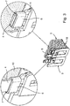
- connection arrangement for an electric pump motor according to the invention, which provides two connection bodies 4, which are made in the manner of a flat plug from an electrically conductive material.
- a wire 1 is also provided, which on the one hand forms a winding 10 and on the other hand is fixed to the connection bodies 4 in two points 2, 3.
- the connection points 2, 3 designed for the cohesive, electrically conductive connection of the wire 1 to the connection body 4 are produced in the present exemplary embodiment of the invention by means of an ultrasonic wire bonding machine. It is the case here that the wire 1 is pressed against the connection body 4 by a tool of the automatic bonding machine and that the tool is excited to produce ultrasonic vibrations. Due to the ultrasonic vibrations, the wire 1 is connected to the connector body 4 in a cohesive manner.
- a determination of the wire 1 on the connector body 4 according to Fig. 1 is achieved in particular before the bond connection is established by winding the wire 1 around the connection body 4 and positioning it in the region of two guide recesses 9 which are formed on two opposite narrow sides of the flat plug 4.
- the connection points 2, 3 are provided on between the guide recesses 9 on the same flat side of the connection body 4.
- a shrink tube 6 with a thermoplastic inner adhesive 7 is applied in the area of the connection point comprising points 2, 3, which electrically insulates and encapsulates the connection point (cf. Fig. 2 ).
- the shrink tube 6 encompasses the connecting body 4 with the wire 1 and the thermoplastic inner adhesive 7.
- the shrink tube 6 is heated after the covering has been produced. In the area of a gap formed between the connector body 4 on the one hand and the shrink tube 6 on the other hand, part of the thermoplastic inner adhesive 7 emerges (not shown).
- connection bodies 4 are used for contacting the windings 10 carried by a coil body 5.
- a further connection body 8 is provided, which is not electrically contacted and remains inoperative in the embodiment shown.
- connection bodies 4 are modified in such a way that the connection bodies 4 designed as flat plugs are provided in the same orientation, whereas in the first exemplary embodiment of the invention, the connection bodies 4 have an orientation that is rotated by 90 ° to one another.
- An elastomer adhesive can be provided as the internal adhesive, and in particular an internal adhesive based on ethylene-vinyl acetate (ethylene-vinyl acetate copolymer).
- the invention is not limited to the embodiment variant shown here.
- the connector body 4 can have a different geometry.
Description
Die Erfindung betrifft einen elektrischen Pumpenmotor, der eine Verbindungsanordnung mit einem Draht und einem Anschlusskörper aufweist.The invention relates to an electric pump motor, which has a connection arrangement with a wire and a connection body.
Aus dem Stand der Technik sind unterschiedliche Kontaktierungsmethoden bekannt, um einen Draht, beispielsweise einen als Wicklung für einen Elektromotor genutzten Aluminiumdraht, mit dem Anschlusskörper zu verbinden und die zwischen dem Draht und dem Anschlusskörper gebildete Verbindungsstelle zu schützen. Die Verbindung wird im industriellen Umfeld beispielsweise durch Löten oder Schweißen oder Ultraschallbonden hergestellt. Ebenso ist bekannt, eine Schneidklemmtechnik zum Verbinden des Drahts mit dem Anschlusskörper zu verwenden.Various contacting methods are known from the prior art in order to connect a wire, for example an aluminum wire used as a winding for an electric motor, to the connection body and to protect the connection point formed between the wire and the connection body. The connection is made in an industrial environment, for example by soldering or welding or ultrasonic bonding. It is also known to use an insulation displacement technique for connecting the wire to the connection body.
Typischerweise bildet die Verbindungsstelle zwischen dem Draht und dem Anschlusskörper eine Schwachstelle, die es zu schützen gilt. Zum Schutz der Verbindungsstelle ist es insofern bekannt, sie mit thermoplastischen oder duroplastischen Materialien zu umspritzen, sie mit Epoxy oder einem ähnlichen Material zu vergießen oder eine Lackschicht aufzubringen. Ebenso ist aus der
Auch wenn sich die bekannten Methoden zur Herstellung einer Umhüllung für die Verbindungsstelle in der Praxis grundsätzlich bewährt haben, besteht insbesondere aufgrund der stetig wachsenden Qualitätsstandards und neuer Prüfroutinen (zum Beispiels Salzsprühnebeltests) das Bestreben, die Kontaktierungsmethoden weiter zu verbessern und den Schutz der Verbindungsstelle zu optimieren.Even though the known methods for producing a sheath for the connection point have proven themselves in practice, there is an endeavor in particular to improve the contacting methods and to optimize the protection of the connection point, in particular due to the constantly increasing quality standards and new test routines (e.g. salt spray tests) .
Aus der
Die
Aufgabe der Erfindung ist es insofern, einen elektrischen Pumpenmotor anzugeben, bei dem die zwischen dem Draht und dem Anschlusskörper gebildete Verbindungsstelle besonders wirtschaftlich hergestellt werden kann und in vorteilhafter Weise gegen schädigende Umgebungseinflüsse geschützt ist.The object of the invention is to provide an electric pump motor in which the connection point formed between the wire and the connection body can be produced particularly economically and is advantageously protected against damaging environmental influences.
Zur Lösung der Aufgabe weist die Erfindung die Merkmale des Patentanspruchs 1 auf.To achieve the object, the invention has the features of claim 1.
Es ist dabei der Draht mit dem Anschlusskörper stoffschlüssig verbunden. Nach dem Herstellen der Verbindung wird der Schrumpfschlauch mit dem Innenkleber über die Verbindungstelle gelegt.The wire is firmly bonded to the connector body. After the connection has been made, the shrink tube with the inner adhesive is placed over the connection point.
Beispielsweise wird der Schrumpfschlauch nach dem Herstellen der Umhüllung erwärmt. Beim Umhüllen der Verbindungsstelle mit dem Schrumpfschlauch beziehungsweise beim Erwärmen des Schrumpfschlauchs kann ein Teil des thermoplastischen Innenklebers durch einen Spalt hindurchtreten, welcher zwischen dem Anschlusskörper und dem Schrumpfschlauch gebildet ist.For example, the shrink tube is heated after the covering has been produced. When enveloping the connection point with the shrink tube or when heating the shrink tube, part of the thermoplastic inner adhesive can pass through a gap which is formed between the connection body and the shrink tube.
Der besondere Vorteil der Erfindung besteht darin, dass die Verbindungsstelle durch den Innenkleber und den Schrumpfschlauch in hervorragender Weise elektrisch isoliert ist. Zugleich sind die Verbindungsstelle und der von der Umhüllung umfasste Teil des Drahts vor Korrosion geschützt. Der Schrumpfschlauch mit dem Innenkleber verhindert den Kontakt mit Sauerstoff beziehungsweise Wasser. Der Schrumpfschlauch ist zudem alterungsbeständig. Durch den Innenkleber sowie den Materialeigenschaften des Schrumpfschlauchs ist Spannungsrissen vorgebeugt beziehungsweise die Neigung zum Verspröden minimiert. Die Verbindungsstelle ist beständig gegen aggressive Medien wie Öl, Säure, Lauge beziehungsweise Salze. Des Weiteren ist eine gute Temperaturbeständigkeit in den normalen Betriebstemperaturbereichen einer Aluminiumwicklung für Spulenkörper gewährleistet. Zudem besteht nicht die Gefahr, dass der Schrumpfschlauch schmilzt, da er bei Temperaturen über den kristallinen Schmelzpunkt nicht mehr fließt, sondern elastisch wird wie ein Elastomer.The particular advantage of the invention is that the connection point is excellently electrically insulated by the inner adhesive and the shrink tube. At the same time, the connection point and the part of the wire covered by the sheath are protected against corrosion. The shrink tube with the inner adhesive prevents contact with oxygen or water. The shrink tube is also resistant to aging. The internal adhesive and the material properties of the shrink tube prevent tension cracks or minimize the tendency to become brittle. The connection point is resistant to aggressive media such as oil, acid, alkali or salts. Furthermore, good temperature resistance is guaranteed in the normal operating temperature ranges of an aluminum winding for coil formers. In addition, there is no risk of the shrink tube melting, since it no longer flows at temperatures above the crystalline melting point, but becomes elastic like an elastomer.
Die gute Isolation führt zudem dazu, dass der Draht, wenn er als Aluminiumlackdraht ausgeführt ist, keine zusätzliche Isolationsschicht beziehungsweise keinen zusätzlichen Isolationsschutz mehr bedarf. Des Weiteren begünstigt der verschrumpfte Schlauch, mit dem die Verbindungsstelle umhüllt ist, eine gleichmäßige und dauerhafte Krafteinwirkung auf die Verbindungspunkte. Sie stellt eine zusätzliche mechanische Sicherung dar und gewährleistet eine dauerhaft gute Verbindung. Wirtschaftlich sind die Investitionskosten in die Anlagentechnik gering. Der Verbindungsprozess ist großserientauglich und gut beherrschbar. Die Taktzeiten sind gering.The good insulation also means that the wire, if it is designed as enamelled aluminum wire, no longer requires an additional insulation layer or additional insulation protection. Furthermore, the shrinked hose, with which the connection point is encased, promotes an even and permanent application of force to the connection points. It represents an additional mechanical security and ensures a permanently good connection. The investment costs in plant technology are low economically. The connection process is suitable for large series and easy to control. The cycle times are low.
Nach der Erfindung ist der Draht auf den Anschlusskörper gebondet. Beim Herstellen der Bondstelle kommt ein Bondautomat zum Einsatz. Dabei wird der Draht von einem Werkzeug des Bondautomaten gegen den Anschlusskörper gedrückt und von dem Werkzeug zu Ultraschallschwingungen angeregt.According to the invention, the wire is bonded to the connection body. A bond machine is used to manufacture the bond site. The wire is pressed against the connection body by a tool of the automatic bonding machine and excited by the tool to ultrasonic vibrations.
Nach einer Weiterbildung der Erfindung werden wenigstens zwei Verbindungspunkte ausgebildet. Die wenigstens zwei und bevorzugt alle Verbindungspunkte werden auf einer gleichen Seite des Anschlusskörpers hergestellt.According to a development of the invention, at least two connection points are formed. The at least two and preferably all connection points are produced on the same side of the connection body.
Vorteilhaft kann durch das Bonden von Draht und Anschlusskörper eine stoffschlüssige Verbindung mit einem geringen elektrischen Übergangswiderstand hergestellt werden. Dabei verbessert sich die Zuverlässigkeit der elektrischen Verbindung, wenn zwei oder mehr Verbindungspunkte zwischen dem Draht und dem Anschlusskörper hergestellt werden. Wirtschaftlich vorteilhaft werden die zwei oder mehr Punkte auf einer gemeinsamen Seite des Anschlusskörpers hergestellt, da ein Umpositionieren des Anschlusskörpers und/oder des Drahts beim Herstellen der Verbindung vermieden werden kann.The bonding of wire and connection body can advantageously produce a material connection with a low electrical contact resistance. The reliability of the electrical connection improves when two or more connection points between the wire and the connector body. The two or more points are produced in an economically advantageous manner on a common side of the connection body, since repositioning of the connection body and / or the wire can be avoided when the connection is made.
Optional kann vorgesehen sein, dass der Draht vor dem Bonden an dem Anschlusskörper wenigstens grob positioniert wird. Der Anschlusskörper kann zu diesem Zweck Führungsmittel für den Draht vorsehen. Beispielsweise können an dem Anschlusskörper Führungsausnehmungen für den Draht vorgesehen werden.Optionally, it can be provided that the wire is at least roughly positioned on the connection body before bonding. For this purpose, the connection body can provide guide means for the wire. For example, guide recesses for the wire can be provided on the connection body.
Für die Auswahl des Schrumpfschlauches sind die Geometrie des zu isolierenden Bereichs, das heißt die Geometrie des Anschlusskörpers und der Verbindungsstelle zu berücksichtigen sowie die Qualitätsanforderungen, die an das Produkt gerichtet sind, in Betracht zu ziehen. Hierbei sind besonders die Dauereinsatztemperatur des Schrumpfschlauchs sowie die der durch den Draht gebildeten Wicklung zu berücksichtigen. Ein weiterer wichtiger Parameter ist das zu schützende Volumen, welches der Innenkleber abdichten muss. Dies muss bei der Auswahl des Schrumpfschlauches ebenfalls berücksichtigt werden.When selecting the shrink tube, the geometry of the area to be insulated, i.e. the geometry of the connector body and the connection point, must be taken into account and the quality requirements for the product must be taken into account. The continuous operating temperature of the shrink tube and the winding formed by the wire must be taken into account. Another important parameter is the volume to be protected, which the inner adhesive must seal. This must also be taken into account when selecting the shrink tube.
Die Verwendung des Schrumpfschlauchs mit dem Innenkleber ist verfahrenstechnisch sehr vorteilhaft, da in einem gemeinsamen Verfahrensschritt der Innenkleber und der Schrumpfschlauch angesetzt werden können. Als Innenkleber kann beispielsweise ein thermoplastischer Innenkleber und insbesondere ein Innenkleber auf Polyamid-Basis zur Anwendung kommen. Beispielsweise kann ein Ethylen-Vinylacetat-Copolymer (Elastomerkleber) als Innenkleber zur Anwendung kommen. Insbesondere bei der Verwendung des thermoplastischen Innenklebers kann ein Schmelzpunkt desselben im Bereich von zirka 135 °C vorgesehen sein.The use of the shrink tube with the inner adhesive is very advantageous in terms of process technology, since the inner adhesive and the shrink tube can be applied in a common process step. For example, a thermoplastic inner adhesive and in particular an inner adhesive based on polyamide can be used as the inner adhesive. For example, an ethylene-vinyl acetate copolymer (elastomer adhesive) can be used as an internal adhesive. In particular when using the thermoplastic inner adhesive, a melting point of the same in the range of approximately 135 ° C. can be provided.
Bei der Erprobung des Kontaktierverfahrens des erfindungsgemässen Pumpenmotors hat sich gezeigt, dass ein sehr guter mechanischer Schutz vor Stößen, Schwingungen und dergleichen hergestellt ist. Die elektrisch leitende Verbindung ist daher dauerhaft hergestellt.When testing the contacting method of the pump motor according to the invention, it has been shown that very good mechanical protection against impacts, vibrations and the like is produced. The electrically conductive connection is therefore permanently established.
Die Verbindungsanordnung umfasst insofern einen Anschlusskörper und einen mit dem Anschlusskörper an einer Verbindungsstelle in wenigstens einem Verbindungspunkt stoffschlüssig festgelegten Draht sowie eine Umhüllung für die Verbindungsstelle. Die Umhüllung weist einen den Draht und den Anschlusskörper im Bereich der Verbindungsstelle umgreifenden thermoplastischen Innenkleber sowie einen den Draht und den Anschlusskörper ebenfalls im Bereich der Verbindungsstelle umgreifenden Schrumpfschlauch auf. Beispielsweise dient ein Flachstecker eines Spulenkörpers als Anschlusskörper.In this respect, the connection arrangement comprises a connection body and a wire which is fixed to the connection body at a connection point in at least one connection point, as well as a sheath for the connection point. The sheath has a thermoplastic inner adhesive encompassing the wire and the connection body in the area of the connection point and a shrink tube likewise encompassing the wire and the connection body in the area of the connection point. For example, a flat plug of a coil former serves as a connection body.
Der Innenkleber ist bevorzugt als Elastomerkleber oder thermoplastischer Innenkleber ausgebildet und zwischen dem Anschlusskörper und dem Schrumpfschlauch vorgesehen.The inner adhesive is preferably designed as an elastomer adhesive or thermoplastic inner adhesive and is provided between the connection body and the shrink tube.
Nach einer bevorzugten Ausführungsform der Erfindung sind der Draht und der Anschlusskörper an wenigstens zwei Punkten miteinander stoffschlüssig verbunden. Die zwei Punkte sind nach der bevorzugten Ausführungsform der Erfindung auf einer gemeinsamen Seite des Anschlusskörpers und bevorzugt auf einer gemeinsamen Flachseite des als Anschlusskörper dienenden Flachsteckers vorgesehen.According to a preferred embodiment of the invention, the wire and the connecting body are integrally connected to one another at at least two points. According to the preferred embodiment of the invention, the two points are provided on a common side of the connection body and preferably on a common flat side of the flat plug serving as the connection body.
Erfindungsgemässe Pumpenmotoren weisen insofern eine genannte Verbindungsanordnung auf, um einen Draht der Wicklungen stoffschlüssig an einem Anschlusskörper des Motors festzulegen.To this extent, pump motors according to the invention have a named connection arrangement in order to firmly attach a wire of the windings to a connection body of the motor.
Die stoffschlüssige Verbindung zwischen dem Draht und dem Anschlusskörper ist nach der Erfindung durch Ultraschalldrahtbonden hergestellt.The integral connection between the wire and the connection body is produced according to the invention by ultrasonic wire bonding.
Aus den weiteren Unteransprüchen und der nachfolgenden Beschreibung sind weitere Vorteile, bevorzugte Merkmale und Einzelheiten der Erfindung zu entnehmen. Die Zeichnungen dienen lediglich beispielhaft der Klarstellung der Erfindung und haben keinen einschränkenden Charakter.Further advantages, preferred features and details of the invention can be gathered from the further subclaims and the description below. The drawings serve only as an example to clarify the invention and have no restrictive character.
Es zeigen:
- Fig. 1
- einen ersten Verfahrensschritt bei der Herstellung einer Verbindungsanordnung eines erfindungsgemässen Pumpenmotors
- Fig. 2
- die Verbindungsanordnung nach
Fig. 1 im fertigen Zustand und - Fig. 3
- eine zweite Ausführungsform der Verbindungsanordnung eines erfindungsgemässen Pumpenmotors.
- Fig. 1
- a first method step in the production of a connection arrangement of a pump motor according to the invention
- Fig. 2
- the connection arrangement according to
Fig. 1 in the finished state and - Fig. 3
- a second embodiment of the connection arrangement of a pump motor according to the invention.
Nach einer ersten Ausführungsform der Erfindung gemäß der
Eine Festlegung des Drahts 1 an dem Anschlusskörper 4 gemäß
Nach dem Herstellen der elektrisch leitenden Verbindung zwischen dem Draht 1 und dem Anschlusskörper 4 wird im Weiteren im Bereich der die Punkte 2, 3 umfassenden Verbindungsstelle ein Schrumpfschlauch 6 mit einem thermoplastischen Innenkleber 7 aufgebracht, der die Verbindungsstelle elektrisch isoliert und kapselt (vergleiche
Die Anschlusskörper 4 dienen der Kontaktierung der von einem Spulenkörper 5 getragenen Wicklungen 10. Vorliegend ist ein weiterer Anschlusskörper 8 vorgesehen, welcher elektrisch nicht kontaktiert ist und in der dargestellten Ausführungsform ohne Funktion bleibt.The
Nach einer zweiten Ausführungsform der Erfindung gemäß
Die Erfindung ist nicht auf die vorstehend diskutierte und in den Figuren gezeigten Ausführungsformen beschränkt.The invention is not restricted to the embodiments discussed above and shown in the figures.
Als Innenkleber kann ein Elastomerkleber vorgesehen werden und insbesondere ein Innenkleber auf Ethylen-Vinylacetat-Basis (Ethylen-Vinylacetat-Copolymer).An elastomer adhesive can be provided as the internal adhesive, and in particular an internal adhesive based on ethylene-vinyl acetate (ethylene-vinyl acetate copolymer).
Gleiche Bauteile und Bauteilfunktionen sind durch gleiche Bezugszeichen gekennzeichnet.The same components and component functions are identified by the same reference symbols.
Die Erfindung ist nicht auf die vorliegend dargestellte Ausführungsvariante beschränkt. Insbesondere kann der Anschlusskörper 4 eine abweichende Geometrie aufweisen.The invention is not limited to the embodiment variant shown here. In particular, the
Claims (7)
- Electric pump motor comprising a winding (10) which is provided on a bobbin (5) of the pump motor, and comprising a connecting element (4) for electrically contacting the winding (10), wherein an aluminium wire (1) of the winding (10) is connected to the connecting element (4) by means of a connection arrangement, said connection arrangement comprising the connecting element (4) and the wire (1) which is bonded to at least one point (2, 3) at a junction point on the connecting element (4), as well as a sheath for the junction point manufactured after the bonding, characterised in that the sheath provides heat-shrink tubing (6) with an adhesive inner liner (7) and grips the wire (1) and the connecting element (4) in the region of the junction point, and in that the bonded connection at the at least one point (2, 3) is made by an automatic bonding machine, wherein in making the connection the wire (1) was pressed against the connecting element (4) by means of a tool of the automatic bonding machine and energised by the tool to produce ultrasonic vibrations.
- Electric pump motor according to claim 1, characterised in that the aluminium wire (1) is an aluminium enamelled wire in design.
- Electric pump motor according to claim 1 or 2, characterised in that the connecting element (4) is provided by means of a blade terminal of the bobbin (5).
- Electric pump motor according to any one of claims 1 to 3, characterised in that the adhesive inner liner (7) is provided between the connecting element (4) and the heat-shrink tubing (6).
- Electric pump motor according to any one of claims 1 to 4, characterised in that the wire (1) is connected to the connecting element (4) at at least two points (2, 3), wherein said points (2, 3) are provided on a common face of the connecting element (4) and in particular, for a pump motor according to claim 3, on an identical flat face of the blade terminal.
- Electric pump motor according to any one of claims 1 to 5, characterised in that a thermoplastic adhesive inner liner and/or an elastomeric adhesive are provided as an adhesive inner liner (7).
- Electric pump motor according to any one of claims 1 to 6, characterised in that at least two and preferably all points (2, 3) of the junction point are manufactured on an identical flat face of the connecting element (4).
Priority Applications (1)
| Application Number | Priority Date | Filing Date | Title |
|---|---|---|---|
| PL17165112T PL3249662T3 (en) | 2016-05-27 | 2017-04-05 | Electric pump motor |
Applications Claiming Priority (2)
| Application Number | Priority Date | Filing Date | Title |
|---|---|---|---|
| DE102016109797 | 2016-05-27 | ||
| DE102017106769 | 2017-03-29 |
Publications (2)
| Publication Number | Publication Date |
|---|---|
| EP3249662A1 EP3249662A1 (en) | 2017-11-29 |
| EP3249662B1 true EP3249662B1 (en) | 2020-05-13 |
Family
ID=58548984
Family Applications (1)
| Application Number | Title | Priority Date | Filing Date |
|---|---|---|---|
| EP17165112.8A Active EP3249662B1 (en) | 2016-05-27 | 2017-04-05 | Electric pump motor |
Country Status (3)
| Country | Link |
|---|---|
| US (1) | US10439301B2 (en) |
| EP (1) | EP3249662B1 (en) |
| PL (1) | PL3249662T3 (en) |
Families Citing this family (1)
| Publication number | Priority date | Publication date | Assignee | Title |
|---|---|---|---|---|
| DE102020122404A1 (en) * | 2020-08-27 | 2022-03-03 | Vem Sachsenwerk Gmbh | Climate-proof magnetic coil |
Family Cites Families (13)
| Publication number | Priority date | Publication date | Assignee | Title |
|---|---|---|---|---|
| DE19808069A1 (en) * | 1998-02-26 | 1999-09-02 | Bosch Gmbh Robert | Process for fixing a rotor winding |
| DE19852929C1 (en) * | 1998-11-17 | 2000-03-30 | Hanning Elektro Werke | Thermal switch for protecting electromagnetic coils in electric motor has connection lugs which enter receptacles of flat pinned plugs from inner surface of end flange of coil |
| JP2002540161A (en) * | 1999-03-26 | 2002-11-26 | ザ ユニヴァーシティー オブ テキサス システム | Polysaccharide modulators and their uses |
| GB2354639B (en) * | 1999-09-17 | 2003-09-24 | Honda Lock Mfg Co Ltd | Electromagnetic coil device |
| JP2008113539A (en) * | 2006-10-03 | 2008-05-15 | Denso Corp | Ac rotary electric machine |
| DE102008009620A1 (en) * | 2008-02-18 | 2009-08-20 | Lapp Engineering & Co. | Connector element with seal in the cable connection area |
| JP5452570B2 (en) * | 2011-11-09 | 2014-03-26 | 三菱電機株式会社 | Rotating electric machine and method of manufacturing stator coil connection unit |
| JP2013246886A (en) * | 2012-05-23 | 2013-12-09 | Auto Network Gijutsu Kenkyusho:Kk | Electric wire with terminal, method of manufacturing the same, and jig |
| JP6127801B2 (en) * | 2013-07-24 | 2017-05-17 | 株式会社オートネットワーク技術研究所 | Manufacturing method of wire harness |
| JP5657085B1 (en) * | 2013-11-08 | 2015-01-21 | 三菱電機株式会社 | Rotating electric machine and method for manufacturing stator for rotating electric machine |
| JP6028934B2 (en) * | 2013-12-19 | 2016-11-24 | 住友電装株式会社 | Electric wire with terminal |
| CN203953323U (en) * | 2014-07-02 | 2014-11-26 | 宁波捷尔天电气有限公司 | A kind of magnechuck |
| CN204741344U (en) | 2015-04-17 | 2015-11-04 | 阿思科尔控股责任有限公司(独资) | Water discharge pump |
-
2017
- 2017-04-05 PL PL17165112T patent/PL3249662T3/en unknown
- 2017-04-05 EP EP17165112.8A patent/EP3249662B1/en active Active
- 2017-05-15 US US15/594,805 patent/US10439301B2/en active Active
Non-Patent Citations (1)
| Title |
|---|
| None * |
Also Published As
| Publication number | Publication date |
|---|---|
| PL3249662T3 (en) | 2020-11-16 |
| EP3249662A1 (en) | 2017-11-29 |
| US10439301B2 (en) | 2019-10-08 |
| US20170346199A1 (en) | 2017-11-30 |
Similar Documents
| Publication | Publication Date | Title |
|---|---|---|
| DE112012003786T5 (en) | connecting terminal | |
| DE102017215091A1 (en) | Arrangement and method for contacting a temperature sensor on a winding head of an electric machine | |
| DE102014109604B4 (en) | Contacting a stranded conductor | |
| EP3155701B1 (en) | Plastic injection overmoulded conductor path structure, and method for producing the plastic injection overmoulded conductor path structure | |
| DE102016102948A1 (en) | Method and device for sealing contact points on electrical line connections | |
| EP3249662B1 (en) | Electric pump motor | |
| DE10054714B4 (en) | Method for sealing a cable or cable set on / in a cable feedthrough element and a cable feedthrough element | |
| DE102013005399A1 (en) | Motor structure with connector or terminal block to which a conductive sealed terminal is soldered " | |
| EP2731203B1 (en) | Method for moisture-proof covering of a junction between an electric conductor and a contact element | |
| DE102011011409A1 (en) | Connector for electrical system of motor car or wind-power plant, has contact part provided at distal end of connector, where connector is flattened in region of contact part and forms radially extending gap between walls of connector | |
| DE102006025661A1 (en) | Contact terminal for electrically connecting braided wire with connector pin, has contact section including recess with size that corresponds to specific surface, where contour of inner periphery of recess is adapted to cross section of pin | |
| DE102011016556B4 (en) | Electrical contact device | |
| WO2012080381A1 (en) | Piezoelectric actuator | |
| EP3466224B1 (en) | Stamped grid arrangement for a transmission control module comprising cu and al stamped grids connected by an encapsulated wire bonding connection | |
| DE102015117020B4 (en) | Method for producing a line seal of a line harness and method for producing a sealed line connection | |
| EP3342008B1 (en) | Method for producing a plug connector, method for amplifying a plug connector and device | |
| DE102008055124A1 (en) | Seal for at least one electrical line | |
| WO2015014647A1 (en) | Crimped connection | |
| DE102015201711A1 (en) | Method for compacting individual wires | |
| DE102004057750A1 (en) | Commutator with an insulating carrier, is formed by arranging the conducting segments to form a ring structure, preparing wire sections, placing the sections in an injection mould and moulding | |
| DE102016221147A1 (en) | Connecting arrangement between a cable lug and an electrical line, method for producing such and electric machine | |
| DE102011011431B4 (en) | Electrical heating element with a connection element and method of manufacturing an electrical heating element with a connection element | |
| DE202020107389U1 (en) | Motor connection arrangement | |
| EP3206268B1 (en) | Method for sealing an electrical coupling element against liquid | |
| DE102010032438A1 (en) | Method for fastening thermocouple wires with metallic component, involves producing electric arc with respect to ends of thermocouple wires protruded from through-hole in metallic component, and welding thermocouple wires in through-hole |
Legal Events
| Date | Code | Title | Description |
|---|---|---|---|
| PUAI | Public reference made under article 153(3) epc to a published international application that has entered the european phase |
Free format text: ORIGINAL CODE: 0009012 |
|
| STAA | Information on the status of an ep patent application or granted ep patent |
Free format text: STATUS: THE APPLICATION HAS BEEN PUBLISHED |
|
| AK | Designated contracting states |
Kind code of ref document: A1 Designated state(s): AL AT BE BG CH CY CZ DE DK EE ES FI FR GB GR HR HU IE IS IT LI LT LU LV MC MK MT NL NO PL PT RO RS SE SI SK SM TR |
|
| AX | Request for extension of the european patent |
Extension state: BA ME |
|
| STAA | Information on the status of an ep patent application or granted ep patent |
Free format text: STATUS: REQUEST FOR EXAMINATION WAS MADE |
|
| 17P | Request for examination filed |
Effective date: 20180523 |
|
| RBV | Designated contracting states (corrected) |
Designated state(s): AL AT BE BG CH CY CZ DE DK EE ES FI FR GB GR HR HU IE IS IT LI LT LU LV MC MK MT NL NO PL PT RO RS SE SI SK SM TR |
|
| GRAP | Despatch of communication of intention to grant a patent |
Free format text: ORIGINAL CODE: EPIDOSNIGR1 |
|
| STAA | Information on the status of an ep patent application or granted ep patent |
Free format text: STATUS: GRANT OF PATENT IS INTENDED |
|
| INTG | Intention to grant announced |
Effective date: 20200210 |
|
| GRAS | Grant fee paid |
Free format text: ORIGINAL CODE: EPIDOSNIGR3 |
|
| GRAA | (expected) grant |
Free format text: ORIGINAL CODE: 0009210 |
|
| STAA | Information on the status of an ep patent application or granted ep patent |
Free format text: STATUS: THE PATENT HAS BEEN GRANTED |
|
| AK | Designated contracting states |
Kind code of ref document: B1 Designated state(s): AL AT BE BG CH CY CZ DE DK EE ES FI FR GB GR HR HU IE IS IT LI LT LU LV MC MK MT NL NO PL PT RO RS SE SI SK SM TR |
|
| REG | Reference to a national code |
Ref country code: GB Ref legal event code: FG4D Free format text: NOT ENGLISH |
|
| REG | Reference to a national code |
Ref country code: CH Ref legal event code: EP |
|
| REG | Reference to a national code |
Ref country code: DE Ref legal event code: R096 Ref document number: 502017005205 Country of ref document: DE |
|
| REG | Reference to a national code |
Ref country code: AT Ref legal event code: REF Ref document number: 1271306 Country of ref document: AT Kind code of ref document: T Effective date: 20200615 |
|
| REG | Reference to a national code |
Ref country code: LT Ref legal event code: MG4D |
|
| REG | Reference to a national code |
Ref country code: NL Ref legal event code: MP Effective date: 20200513 |
|
| PG25 | Lapsed in a contracting state [announced via postgrant information from national office to epo] |
Ref country code: IS Free format text: LAPSE BECAUSE OF FAILURE TO SUBMIT A TRANSLATION OF THE DESCRIPTION OR TO PAY THE FEE WITHIN THE PRESCRIBED TIME-LIMIT Effective date: 20200913 Ref country code: PT Free format text: LAPSE BECAUSE OF FAILURE TO SUBMIT A TRANSLATION OF THE DESCRIPTION OR TO PAY THE FEE WITHIN THE PRESCRIBED TIME-LIMIT Effective date: 20200914 Ref country code: SE Free format text: LAPSE BECAUSE OF FAILURE TO SUBMIT A TRANSLATION OF THE DESCRIPTION OR TO PAY THE FEE WITHIN THE PRESCRIBED TIME-LIMIT Effective date: 20200513 Ref country code: FI Free format text: LAPSE BECAUSE OF FAILURE TO SUBMIT A TRANSLATION OF THE DESCRIPTION OR TO PAY THE FEE WITHIN THE PRESCRIBED TIME-LIMIT Effective date: 20200513 Ref country code: NO Free format text: LAPSE BECAUSE OF FAILURE TO SUBMIT A TRANSLATION OF THE DESCRIPTION OR TO PAY THE FEE WITHIN THE PRESCRIBED TIME-LIMIT Effective date: 20200813 Ref country code: GR Free format text: LAPSE BECAUSE OF FAILURE TO SUBMIT A TRANSLATION OF THE DESCRIPTION OR TO PAY THE FEE WITHIN THE PRESCRIBED TIME-LIMIT Effective date: 20200814 Ref country code: LT Free format text: LAPSE BECAUSE OF FAILURE TO SUBMIT A TRANSLATION OF THE DESCRIPTION OR TO PAY THE FEE WITHIN THE PRESCRIBED TIME-LIMIT Effective date: 20200513 |
|
| PG25 | Lapsed in a contracting state [announced via postgrant information from national office to epo] |
Ref country code: LV Free format text: LAPSE BECAUSE OF FAILURE TO SUBMIT A TRANSLATION OF THE DESCRIPTION OR TO PAY THE FEE WITHIN THE PRESCRIBED TIME-LIMIT Effective date: 20200513 Ref country code: BG Free format text: LAPSE BECAUSE OF FAILURE TO SUBMIT A TRANSLATION OF THE DESCRIPTION OR TO PAY THE FEE WITHIN THE PRESCRIBED TIME-LIMIT Effective date: 20200813 Ref country code: RS Free format text: LAPSE BECAUSE OF FAILURE TO SUBMIT A TRANSLATION OF THE DESCRIPTION OR TO PAY THE FEE WITHIN THE PRESCRIBED TIME-LIMIT Effective date: 20200513 Ref country code: HR Free format text: LAPSE BECAUSE OF FAILURE TO SUBMIT A TRANSLATION OF THE DESCRIPTION OR TO PAY THE FEE WITHIN THE PRESCRIBED TIME-LIMIT Effective date: 20200513 |
|
| PG25 | Lapsed in a contracting state [announced via postgrant information from national office to epo] |
Ref country code: NL Free format text: LAPSE BECAUSE OF FAILURE TO SUBMIT A TRANSLATION OF THE DESCRIPTION OR TO PAY THE FEE WITHIN THE PRESCRIBED TIME-LIMIT Effective date: 20200513 Ref country code: AL Free format text: LAPSE BECAUSE OF FAILURE TO SUBMIT A TRANSLATION OF THE DESCRIPTION OR TO PAY THE FEE WITHIN THE PRESCRIBED TIME-LIMIT Effective date: 20200513 |
|
| PG25 | Lapsed in a contracting state [announced via postgrant information from national office to epo] |
Ref country code: SM Free format text: LAPSE BECAUSE OF FAILURE TO SUBMIT A TRANSLATION OF THE DESCRIPTION OR TO PAY THE FEE WITHIN THE PRESCRIBED TIME-LIMIT Effective date: 20200513 Ref country code: EE Free format text: LAPSE BECAUSE OF FAILURE TO SUBMIT A TRANSLATION OF THE DESCRIPTION OR TO PAY THE FEE WITHIN THE PRESCRIBED TIME-LIMIT Effective date: 20200513 Ref country code: DK Free format text: LAPSE BECAUSE OF FAILURE TO SUBMIT A TRANSLATION OF THE DESCRIPTION OR TO PAY THE FEE WITHIN THE PRESCRIBED TIME-LIMIT Effective date: 20200513 Ref country code: CZ Free format text: LAPSE BECAUSE OF FAILURE TO SUBMIT A TRANSLATION OF THE DESCRIPTION OR TO PAY THE FEE WITHIN THE PRESCRIBED TIME-LIMIT Effective date: 20200513 Ref country code: RO Free format text: LAPSE BECAUSE OF FAILURE TO SUBMIT A TRANSLATION OF THE DESCRIPTION OR TO PAY THE FEE WITHIN THE PRESCRIBED TIME-LIMIT Effective date: 20200513 Ref country code: ES Free format text: LAPSE BECAUSE OF FAILURE TO SUBMIT A TRANSLATION OF THE DESCRIPTION OR TO PAY THE FEE WITHIN THE PRESCRIBED TIME-LIMIT Effective date: 20200513 |
|
| REG | Reference to a national code |
Ref country code: DE Ref legal event code: R097 Ref document number: 502017005205 Country of ref document: DE |
|
| PG25 | Lapsed in a contracting state [announced via postgrant information from national office to epo] |
Ref country code: SK Free format text: LAPSE BECAUSE OF FAILURE TO SUBMIT A TRANSLATION OF THE DESCRIPTION OR TO PAY THE FEE WITHIN THE PRESCRIBED TIME-LIMIT Effective date: 20200513 |
|
| PLBE | No opposition filed within time limit |
Free format text: ORIGINAL CODE: 0009261 |
|
| STAA | Information on the status of an ep patent application or granted ep patent |
Free format text: STATUS: NO OPPOSITION FILED WITHIN TIME LIMIT |
|
| 26N | No opposition filed |
Effective date: 20210216 |
|
| PG25 | Lapsed in a contracting state [announced via postgrant information from national office to epo] |
Ref country code: SI Free format text: LAPSE BECAUSE OF FAILURE TO SUBMIT A TRANSLATION OF THE DESCRIPTION OR TO PAY THE FEE WITHIN THE PRESCRIBED TIME-LIMIT Effective date: 20200513 |
|
| PG25 | Lapsed in a contracting state [announced via postgrant information from national office to epo] |
Ref country code: MC Free format text: LAPSE BECAUSE OF FAILURE TO SUBMIT A TRANSLATION OF THE DESCRIPTION OR TO PAY THE FEE WITHIN THE PRESCRIBED TIME-LIMIT Effective date: 20200513 |
|
| GBPC | Gb: european patent ceased through non-payment of renewal fee |
Effective date: 20210405 |
|
| PG25 | Lapsed in a contracting state [announced via postgrant information from national office to epo] |
Ref country code: LU Free format text: LAPSE BECAUSE OF NON-PAYMENT OF DUE FEES Effective date: 20210405 |
|
| REG | Reference to a national code |
Ref country code: BE Ref legal event code: MM Effective date: 20210430 |
|
| PG25 | Lapsed in a contracting state [announced via postgrant information from national office to epo] |
Ref country code: LI Free format text: LAPSE BECAUSE OF NON-PAYMENT OF DUE FEES Effective date: 20210430 Ref country code: CH Free format text: LAPSE BECAUSE OF NON-PAYMENT OF DUE FEES Effective date: 20210430 Ref country code: GB Free format text: LAPSE BECAUSE OF NON-PAYMENT OF DUE FEES Effective date: 20210405 Ref country code: FR Free format text: LAPSE BECAUSE OF NON-PAYMENT OF DUE FEES Effective date: 20210430 |
|
| PG25 | Lapsed in a contracting state [announced via postgrant information from national office to epo] |
Ref country code: IE Free format text: LAPSE BECAUSE OF NON-PAYMENT OF DUE FEES Effective date: 20210405 |
|
| PG25 | Lapsed in a contracting state [announced via postgrant information from national office to epo] |
Ref country code: BE Free format text: LAPSE BECAUSE OF NON-PAYMENT OF DUE FEES Effective date: 20210430 |
|
| PG25 | Lapsed in a contracting state [announced via postgrant information from national office to epo] |
Ref country code: HU Free format text: LAPSE BECAUSE OF FAILURE TO SUBMIT A TRANSLATION OF THE DESCRIPTION OR TO PAY THE FEE WITHIN THE PRESCRIBED TIME-LIMIT; INVALID AB INITIO Effective date: 20170405 |
|
| PGFP | Annual fee paid to national office [announced via postgrant information from national office to epo] |
Ref country code: PL Payment date: 20230327 Year of fee payment: 7 |
|
| REG | Reference to a national code |
Ref country code: AT Ref legal event code: MM01 Ref document number: 1271306 Country of ref document: AT Kind code of ref document: T Effective date: 20220405 |
|
| PG25 | Lapsed in a contracting state [announced via postgrant information from national office to epo] |
Ref country code: CY Free format text: LAPSE BECAUSE OF FAILURE TO SUBMIT A TRANSLATION OF THE DESCRIPTION OR TO PAY THE FEE WITHIN THE PRESCRIBED TIME-LIMIT Effective date: 20200513 |
|
| P01 | Opt-out of the competence of the unified patent court (upc) registered |
Effective date: 20230530 |
|
| PG25 | Lapsed in a contracting state [announced via postgrant information from national office to epo] |
Ref country code: AT Free format text: LAPSE BECAUSE OF NON-PAYMENT OF DUE FEES Effective date: 20220405 |
|
| PGFP | Annual fee paid to national office [announced via postgrant information from national office to epo] |
Ref country code: IT Payment date: 20230428 Year of fee payment: 7 Ref country code: DE Payment date: 20230418 Year of fee payment: 7 |
|
| REG | Reference to a national code |
Ref country code: DE Ref legal event code: R082 Ref document number: 502017005205 Country of ref document: DE Representative=s name: WICKORD BUSER PATENTANWAELTE PARTG MBB, DE |