EP3248624A1 - Device for monitoring a blood flow occurring in a haemorrhagic region - Google Patents
Device for monitoring a blood flow occurring in a haemorrhagic region Download PDFInfo
- Publication number
- EP3248624A1 EP3248624A1 EP17169826.9A EP17169826A EP3248624A1 EP 3248624 A1 EP3248624 A1 EP 3248624A1 EP 17169826 A EP17169826 A EP 17169826A EP 3248624 A1 EP3248624 A1 EP 3248624A1
- Authority
- EP
- European Patent Office
- Prior art keywords
- zone
- hollow
- faces
- plate
- bottom wall
- Prior art date
- Legal status (The legal status is an assumption and is not a legal conclusion. Google has not performed a legal analysis and makes no representation as to the accuracy of the status listed.)
- Granted
Links
- 230000002008 hemorrhagic effect Effects 0.000 title claims abstract description 15
- 230000017531 blood circulation Effects 0.000 title claims abstract description 12
- 238000012544 monitoring process Methods 0.000 title claims 2
- 210000000056 organ Anatomy 0.000 claims description 11
- 210000004291 uterus Anatomy 0.000 claims description 10
- 230000000740 bleeding effect Effects 0.000 claims description 7
- 210000002784 stomach Anatomy 0.000 claims description 5
- 210000003238 esophagus Anatomy 0.000 claims description 3
- 238000003780 insertion Methods 0.000 claims description 3
- 230000037431 insertion Effects 0.000 claims description 3
- 230000003169 placental effect Effects 0.000 claims description 2
- 239000004744 fabric Substances 0.000 abstract description 17
- 239000011796 hollow space material Substances 0.000 abstract description 16
- 230000002093 peripheral effect Effects 0.000 abstract description 15
- 210000001519 tissue Anatomy 0.000 description 27
- 206010052428 Wound Diseases 0.000 description 17
- 208000027418 Wounds and injury Diseases 0.000 description 16
- 208000032843 Hemorrhage Diseases 0.000 description 14
- 239000003292 glue Substances 0.000 description 11
- 230000002439 hemostatic effect Effects 0.000 description 9
- 229920001296 polysiloxane Polymers 0.000 description 8
- 230000023597 hemostasis Effects 0.000 description 4
- 238000012423 maintenance Methods 0.000 description 4
- 241001080024 Telles Species 0.000 description 3
- 230000000694 effects Effects 0.000 description 3
- 238000000034 method Methods 0.000 description 3
- 240000008042 Zea mays Species 0.000 description 2
- 229940030225 antihemorrhagics Drugs 0.000 description 2
- 238000012550 audit Methods 0.000 description 2
- 210000002318 cardia Anatomy 0.000 description 2
- 210000001072 colon Anatomy 0.000 description 2
- 230000000025 haemostatic effect Effects 0.000 description 2
- 210000000936 intestine Anatomy 0.000 description 2
- 230000003902 lesion Effects 0.000 description 2
- 230000014759 maintenance of location Effects 0.000 description 2
- 239000000463 material Substances 0.000 description 2
- 210000004379 membrane Anatomy 0.000 description 2
- 239000012528 membrane Substances 0.000 description 2
- 229920003052 natural elastomer Polymers 0.000 description 2
- 229920001194 natural rubber Polymers 0.000 description 2
- 210000002826 placenta Anatomy 0.000 description 2
- 239000004033 plastic Substances 0.000 description 2
- 229920003023 plastic Polymers 0.000 description 2
- 238000007789 sealing Methods 0.000 description 2
- 238000001356 surgical procedure Methods 0.000 description 2
- 229920003051 synthetic elastomer Polymers 0.000 description 2
- 239000005061 synthetic rubber Substances 0.000 description 2
- 230000005944 tissue migration Effects 0.000 description 2
- 239000011800 void material Substances 0.000 description 2
- 208000031968 Cadaver Diseases 0.000 description 1
- 241001465754 Metazoa Species 0.000 description 1
- 208000024248 Vascular System injury Diseases 0.000 description 1
- 208000012339 Vascular injury Diseases 0.000 description 1
- 238000004026 adhesive bonding Methods 0.000 description 1
- 230000002421 anti-septic effect Effects 0.000 description 1
- 230000003115 biocidal effect Effects 0.000 description 1
- 239000008280 blood Substances 0.000 description 1
- 210000004369 blood Anatomy 0.000 description 1
- 238000003776 cleavage reaction Methods 0.000 description 1
- 238000005315 distribution function Methods 0.000 description 1
- 230000009977 dual effect Effects 0.000 description 1
- 210000001198 duodenum Anatomy 0.000 description 1
- 229920001971 elastomer Polymers 0.000 description 1
- 210000001035 gastrointestinal tract Anatomy 0.000 description 1
- 230000035876 healing Effects 0.000 description 1
- 210000002216 heart Anatomy 0.000 description 1
- 238000000265 homogenisation Methods 0.000 description 1
- 208000014674 injury Diseases 0.000 description 1
- 238000009434 installation Methods 0.000 description 1
- 239000007788 liquid Substances 0.000 description 1
- 210000004185 liver Anatomy 0.000 description 1
- 239000002184 metal Substances 0.000 description 1
- 239000002245 particle Substances 0.000 description 1
- 210000004303 peritoneum Anatomy 0.000 description 1
- 210000004224 pleura Anatomy 0.000 description 1
- 230000001737 promoting effect Effects 0.000 description 1
- 230000002685 pulmonary effect Effects 0.000 description 1
- 239000005060 rubber Substances 0.000 description 1
- 230000007017 scission Effects 0.000 description 1
- 239000007787 solid Substances 0.000 description 1
- 210000000952 spleen Anatomy 0.000 description 1
- 230000008733 trauma Effects 0.000 description 1
- 230000000007 visual effect Effects 0.000 description 1
Images


Classifications
-
- A—HUMAN NECESSITIES
- A61—MEDICAL OR VETERINARY SCIENCE; HYGIENE
- A61B—DIAGNOSIS; SURGERY; IDENTIFICATION
- A61B17/00—Surgical instruments, devices or methods, e.g. tourniquets
- A61B17/08—Wound clamps or clips, i.e. not or only partly penetrating the tissue ; Devices for bringing together the edges of a wound
-
- A—HUMAN NECESSITIES
- A61—MEDICAL OR VETERINARY SCIENCE; HYGIENE
- A61B—DIAGNOSIS; SURGERY; IDENTIFICATION
- A61B17/00—Surgical instruments, devices or methods, e.g. tourniquets
- A61B17/12—Surgical instruments, devices or methods, e.g. tourniquets for ligaturing or otherwise compressing tubular parts of the body, e.g. blood vessels, umbilical cord
- A61B17/12022—Occluding by internal devices, e.g. balloons or releasable wires
-
- A—HUMAN NECESSITIES
- A61—MEDICAL OR VETERINARY SCIENCE; HYGIENE
- A61B—DIAGNOSIS; SURGERY; IDENTIFICATION
- A61B17/00—Surgical instruments, devices or methods, e.g. tourniquets
- A61B17/42—Gynaecological or obstetrical instruments or methods
-
- A—HUMAN NECESSITIES
- A61—MEDICAL OR VETERINARY SCIENCE; HYGIENE
- A61M—DEVICES FOR INTRODUCING MEDIA INTO, OR ONTO, THE BODY; DEVICES FOR TRANSDUCING BODY MEDIA OR FOR TAKING MEDIA FROM THE BODY; DEVICES FOR PRODUCING OR ENDING SLEEP OR STUPOR
- A61M1/00—Suction or pumping devices for medical purposes; Devices for carrying-off, for treatment of, or for carrying-over, body-liquids; Drainage systems
- A61M1/90—Negative pressure wound therapy devices, i.e. devices for applying suction to a wound to promote healing, e.g. including a vacuum dressing
-
- A—HUMAN NECESSITIES
- A61—MEDICAL OR VETERINARY SCIENCE; HYGIENE
- A61B—DIAGNOSIS; SURGERY; IDENTIFICATION
- A61B17/00—Surgical instruments, devices or methods, e.g. tourniquets
- A61B17/00491—Surgical glue applicators
-
- A—HUMAN NECESSITIES
- A61—MEDICAL OR VETERINARY SCIENCE; HYGIENE
- A61B—DIAGNOSIS; SURGERY; IDENTIFICATION
- A61B17/00—Surgical instruments, devices or methods, e.g. tourniquets
- A61B17/12—Surgical instruments, devices or methods, e.g. tourniquets for ligaturing or otherwise compressing tubular parts of the body, e.g. blood vessels, umbilical cord
- A61B17/12009—Implements for ligaturing other than by clamps or clips, e.g. using a loop with a slip knot
- A61B17/12013—Implements for ligaturing other than by clamps or clips, e.g. using a loop with a slip knot for use in minimally invasive surgery, e.g. endoscopic surgery
-
- A—HUMAN NECESSITIES
- A61—MEDICAL OR VETERINARY SCIENCE; HYGIENE
- A61B—DIAGNOSIS; SURGERY; IDENTIFICATION
- A61B17/00—Surgical instruments, devices or methods, e.g. tourniquets
- A61B2017/00831—Material properties
- A61B2017/00884—Material properties enhancing wound closure
-
- A—HUMAN NECESSITIES
- A61—MEDICAL OR VETERINARY SCIENCE; HYGIENE
- A61B—DIAGNOSIS; SURGERY; IDENTIFICATION
- A61B17/00—Surgical instruments, devices or methods, e.g. tourniquets
- A61B2017/00831—Material properties
- A61B2017/00889—Material properties antimicrobial, disinfectant
-
- A—HUMAN NECESSITIES
- A61—MEDICAL OR VETERINARY SCIENCE; HYGIENE
- A61B—DIAGNOSIS; SURGERY; IDENTIFICATION
- A61B17/00—Surgical instruments, devices or methods, e.g. tourniquets
- A61B2017/00831—Material properties
- A61B2017/00893—Material properties pharmaceutically effective
-
- A—HUMAN NECESSITIES
- A61—MEDICAL OR VETERINARY SCIENCE; HYGIENE
- A61B—DIAGNOSIS; SURGERY; IDENTIFICATION
- A61B17/00—Surgical instruments, devices or methods, e.g. tourniquets
- A61B17/12—Surgical instruments, devices or methods, e.g. tourniquets for ligaturing or otherwise compressing tubular parts of the body, e.g. blood vessels, umbilical cord
- A61B2017/12004—Surgical instruments, devices or methods, e.g. tourniquets for ligaturing or otherwise compressing tubular parts of the body, e.g. blood vessels, umbilical cord for haemostasis, for prevention of bleeding
-
- A—HUMAN NECESSITIES
- A61—MEDICAL OR VETERINARY SCIENCE; HYGIENE
- A61B—DIAGNOSIS; SURGERY; IDENTIFICATION
- A61B17/00—Surgical instruments, devices or methods, e.g. tourniquets
- A61B17/30—Surgical pincettes without pivotal connections
- A61B2017/306—Surgical pincettes without pivotal connections holding by means of suction
- A61B2017/308—Surgical pincettes without pivotal connections holding by means of suction with suction cups
-
- A—HUMAN NECESSITIES
- A61—MEDICAL OR VETERINARY SCIENCE; HYGIENE
- A61B—DIAGNOSIS; SURGERY; IDENTIFICATION
- A61B17/00—Surgical instruments, devices or methods, e.g. tourniquets
- A61B17/42—Gynaecological or obstetrical instruments or methods
- A61B2017/4216—Operations on uterus, e.g. endometrium
-
- A—HUMAN NECESSITIES
- A61—MEDICAL OR VETERINARY SCIENCE; HYGIENE
- A61B—DIAGNOSIS; SURGERY; IDENTIFICATION
- A61B90/00—Instruments, implements or accessories specially adapted for surgery or diagnosis and not covered by any of the groups A61B1/00 - A61B50/00, e.g. for luxation treatment or for protecting wound edges
- A61B90/36—Image-producing devices or illumination devices not otherwise provided for
- A61B90/361—Image-producing devices, e.g. surgical cameras
-
- A—HUMAN NECESSITIES
- A61—MEDICAL OR VETERINARY SCIENCE; HYGIENE
- A61M—DEVICES FOR INTRODUCING MEDIA INTO, OR ONTO, THE BODY; DEVICES FOR TRANSDUCING BODY MEDIA OR FOR TAKING MEDIA FROM THE BODY; DEVICES FOR PRODUCING OR ENDING SLEEP OR STUPOR
- A61M27/00—Drainage appliance for wounds or the like, i.e. wound drains, implanted drains
Definitions
- the present invention relates to a device for controlling a blood flow occurring in a hemorrhagic zone, particularly in a point zone (the largest diameter of which is less than about 10 mm) of the human body or more generally animal.
- a first technical problem arising from the state of the art is the good maintenance of such a device against this wound or tissue.
- a second technical problem arising from the state of the art is the close maintenance of two opposite walls of a "hollow" organ such as, for example, the uterus in the case of haemorrhages that may occur occasionally. delivery during the delivery of a patient, in the inner wall of her uterus.
- the object of the invention is to solve this first or second problem.
- the hollow stud may be arranged to, when its recessed side is in contact with the area, be isolated from the vacuum created in space.
- the hollow stud may not include a hole connecting its hollow interior to the space.
- the hollow stud may have a cylindrical shape of axis of symmetry substantially perpendicular to the bottom wall.
- the hollow stud may be arranged to be filled with a product such as hemostatic glue or a hemostatic product.
- the bottom wall may be arranged to be pierced by a syringe to inject a product such as glue or hemostatic product into the hollow stud without passing through the connecting means between the hollow space and the suction means.
- the connecting means can be arranged to connect the hollow space without intermediate manifold housing formed in the thickness of the bottom wall.
- the hollow stud may be centered on the bottom wall.
- the hollow stud may be arranged to receive on the side of the zone a recessed crown and surrounding the hollow stud so that the junction between the hollow stud and the crown is hermetic.
- the device according to the invention may comprise a recessed crown and surrounding the hollow stud on the side of the zone so that the junction between the hollow stud and the crown is hermetic.
- the crown may have a cylindrical shape.
- the crown may have a flared shape towards the zone.
- the device according to the invention may comprise a skirt disposed between the peripheral support means and the hollow stud surrounding the hollow stud, and arranged to be in contact with the zone when creating the vacuum in the space.
- the skirt can be centered on the bottom wall.
- the skirt may be provided with teeth directed towards the area and arranged to be in contact with the area when creating the void in the space.
- the peripheral support means may be arranged to accommodate an additional piece to modify the plate surface or to modify the profile.
- the bottom wall can be waterproof and impervious.
- the device according to the invention can integrate a camera to help position the plate on the zone.
- Each of the faces of the plate may be provided, towards the outside of the device, with relief patterns.
- the patterns can be evenly distributed on the faces, with a substantially constant surface density.
- a method for controlling a blood flow occurring in a biological fenced area wherein the device according to the invention is located on the hemorrhagic zone.
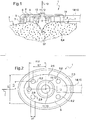
- the figure 1 is a profile section view along axis I of the figure 2 .
- the device 1 for the control of a blood flow occurring in a hemorrhagic zone 4 of a biological tissue 8, comprises a flat flexible plate 2.
- the plate has a round or oval shape.
- the flexible plate 2 is made of natural or synthetic rubber or plastic material of the silicone type.
- the connecting means 14 comprise a tube 15 (or connecting duct) opening inside the hollow space 6.
- the hollow stud 11 has a cylindrical shape with an axis of symmetry substantially perpendicular to the bottom wall 5.
- the hollow stud 11 is centered on the bottom wall 5.
- the bottom wall 5 is impermeable and impermeable, as are the peripheral support means 3. Impervious means that it isolates and does not allow itself to propagate through it a liquid or a pressure difference.
- the peripheral support means 3 of the flexible plate are constituted by a flexible edge surrounding the bottom wall 5 of this plate and secured thereto.
- the device 1 further comprises intermittent intermittent means 9 arranged to stiffen the flexible plate 2, these intermediate means being arranged between this zone 4 and the bottom wall 5.
- the discontinuous interleaved means 9 are further intended to facilitate the propagation of the vacuum in the hollow space 6 and to limit the sliding of the device according to the invention on the surface 7.
- Interleaved discontinuous means 9 comprise studs 9 distributed on the bottom wall.
- the intermediate means consist of a plurality of spacing studs 9, preferably identical, equidistant and regularly distributed in the extent of the flexible plate 2, able to come into contact with one of their ends with the hemorrhagic zone, these studs 9 being integral with the bottom wall 5 by their opposite ends.
- the studs 9 have a solid cylindrical profile, circular section.
- the intermediate means 9 are made of the same material as the plate, namely natural or synthetic rubber or silicone plastic.
- the plate 2 of the device 1 forms a flat suction cup for sealing, able to surround and to be tightly applied against the wound 37 or the tissue zone 8 to be treated, which is the site of haemorrhage or blood flow.
- this sucker contacting the periphery of the zone 4 of fabric 8 and delimiting an internal volume 6 sealingly connected by a catheter or a similar connecting tube 15 to an external suction and evacuation member , creating in this volume 6, between the suction cup and the zone 4 of tissue 8, a depression of determined value.
- the wound 37 is closed by tissue migration under the effect of the depression created, the internal support members 9, 11 now the fabric 8 substantially in place.
- the hollow stud 11 comprises a circumferential wall 12 surrounding a hollow interior 13.
- the wall 12 is impermeable.
- the hollow stud 11 is arranged so that, when its recessed side is in contact with the zone 4, its wall 12 surrounds the wound 37 so that the wound 37 is arranged opposite the hollow interior 13.
- the hollow stud 11 is arranged so that, when its recessed side is in contact with the zone 4, its hollow interior 13 is isolated from the vacuum created in the space 6.
- the hollow stud 11 does not comprise in its wall 12 hole connecting its recessed interior 13 to the space 6.
- the hollow stud 11 is arranged to be filled with glue or hemostatic product, more exactly the hollow interior 13 is arranged to be filled with glue or haemostatic product
- the bottom wall 5 is arranged to be pierced by a syringe (for example along the axis 10, from the outside of the device 1 towards the hollow interior 13) for injecting glue or hemostatic product into the hollow interior. 13 of the stud 11 without crossing the connection means 14 between the hollow space 6 and the suction means.
- the connection means 14 are arranged to connect the hollow space 6 directly to the connecting duct 15 without intermediate collector housing formed in the thickness of the bottom wall 5.
- the glue or the hemostatic product is inserted beforehand into the hollow space 13 before the plate 2 is applied to the wound 37.
- glue or hemostatic product is inserted beforehand into the hollow space 13 before the plate 2 is applied to the wound 37.
- glue can be inserted into the hollow interior, for example a sticky product, antiseptic, healing, and / or antibiotic
- the figure 3 is a profile section view along axis II of the figure 4 .
- This second embodiment is identical to the first mode, except that it is larger and comprises a greater number of pads 9.
- the hollow stud 11 is arranged to receive on the side of the zone 4 (that is to say on its hollow side) a removable crown 17 hollowed and surrounding the hollow stud 11 so that the junction between the hollow stud 11 and the ring 17 is hermetic.
- the device 1, 16 thus typically comprises a recessed ring and surrounding the hollow stud 11 on the side of the zone 4 so that the junction between the hollow stud 11 and the ring is hermetic.
- the crown 17 improves the maintenance and closure of the wound.
- the hollow stud may be provided with microstructured teeth.
- the ring 17 is provided with microstructured teeth.
- the peripheral support means 3 are arranged to accommodate an additional piece 20 for modifying the plate surface or to modify the profile thereof.
- the additional piece is fixed on the peripheral support means by gluing, clipping or adhesion of surfaces such as for example two smooth surfaces of rubber that can stick and peel off a large number of times.
- the properties of adhesion and retention of the device 1, 16 to the fabric 8 can be modified and adapted to measure.
- the additional piece 20 is provided with microstructured teeth 22 directed towards the fabric 8 and arranged to be in contact with the fabric 8 when a vacuum is created in the space 6.
- the additional piece 20 ensures a better hold of the device on the fabric 8, by hanging on the fabric 8 of the microstructures 22 tooth-shaped.
- any of the alternative embodiments of the device according to the invention may further comprise, as shown in the Figures 12 and 13 , a removable skirt 21 disposed between the peripheral support means 3 and the hollow stud 11 surrounding the hollow stud 11, and arranged to be in contact with the fabric 8 when the vacuum is created in the space 6.
- the skirt 21 is centered on the bottom wall 5.
- the skirt provides a better hold of the device on the fabric 8.
- the device 1, 16 can integrate a camera 24 to help the practitioner to position the plate 2 on the zone 4 and center the plate 2 relative to the wound 37.
- the camera is arranged to visualize the tissue via the hollow interior 23 when the recessed side of the stud 11 is in contact with the zone 4.
- a cable 25 connects the camera 24 to remote means (not shown) to receive visual data from the camera.
- the camera is powered locally (battery, battery) or via cable 25.
- the cable goes from the camera 24 to the connection means 14 and then follows the path of the conduit 15.
- the camera is off-center with respect to the central axis 10 of the pad 11, to allow a syringe to pierce the plate 2 to inject a product into the hollow interior 13 without the risk of damaging the camera 24 or the cable 25. advantageously so as not to have doubts about the position of the camera 24 and the cable, the camera is shifted towards the connection means 14.
- the pads 9 are non-slip pads.
- the connecting means 14 open directly into the hollow stud 11, in the base of the hollow stud.
- connection means 14 open into the hollow stud 11 from above the hollow stud on the side of the bottom wall 5.
- the hollow interior 13 has a concave inner shape.
- the wall 12 is perforated (holes 41) to allow the suction to be transmitted between the inside 13 of the pad 11 and the space 6.
- the connecting means 14 open into the hollow stud 11 with a hole that takes a cross shape (illustrated in FIG. figure 18 ) in order to improve the depression and its homogenization.
- the device according to the invention comprises a portion of silicone capable of being applied to the biological tissue 8 and of different hardness and less than the hardness of the wall of the invention. background 5.
- the function of the bottom wall 5 is to ensure sufficient rigidity of the device to resist the vacuum due to suction.
- the bottom wall has a hardness of between 35 and 85 Shore A, preferably substantially equal to 50 Shore A.
- the function of the clean part to be applied on the biological tissue is to adapt to the shape of the wound or the tissue 8.
- This clean part to apply on the biological tissue and hardness different to the hardness of the bottom wall has a hardness between 0 and 50 Shore A, preferably substantially equal to 35 Shore A.
- the additional piece 20 is equipped with an intermediate silicone seal 40 of hardness less than the hardness of the additional piece 20 and arranged so as to be situated between the additional piece 20 and the biological tissue. This makes it possible to adapt even better to the shape of the wound or the fabric 8.
- the additional piece 20 is provided with a slot 39 in the form of a closed loop and arranged to receive the seal 40.
- the seal 40 has a hardness included between 0 and 10 shore 00 (ie according to Shore 00 scale), preferably substantially equal to 5 shore 00.
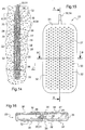
- the figure 14 is a profile section view along the axis AA of the figure 15 .
- the figure 16 is a profile section view along axis I of the figure 14 .
- the figure 3 is a profile section view along axis II of the figure 4 .
- the device can communicate the suction to the tissue 8 simultaneously via the two opposite faces 27, 28, and thus makes it possible to keep two opposite walls 33, 34 of a "hollow" organ, such as the stomach or the stomach, side by side. esophagus, or preferentially the uterus in the case of haemorrhage that may occur during delivery during the delivery of a patient, in the inner wall of her uterus.
- each of the faces 27, 28 of the plate 23 is provided, outwardly of the device 23, relief patterns 35 in the form of a bump.
- the patterns 25 are distributed on the faces 27, 28 in a regular manner, with a substantially constant surface density. For reasons of simplification, these reasons are not illustrated on the figure 15 .
- the role of these patterns is to improve the sealing of the device 23 at the various locations of the bleeding.
- the tube 31 extends inside the volume 29, over the entire length of the volume 29.
- This tube is provided, throughout its length inside the space 29, with pairs of lateral holes 36 which communicate the inside of the tube 31 to the volume 29, so that the depression is uniform inside. of space 29.
Abstract
La présente invention concerne un dispositif pour le contrôle d'un écoulement sanguin se produisant dans une zone hémorragique (4) d'un tissu biologique (8), comprenant une plaque souple (2), cette plaque étant agencée pour être disposée en regard de cette zone (4), ladite plaque souple comprenant : des moyens d'appui périphériques (3) sensiblement étanches, propres à s'appliquer sur le tissu biologique (8) en entourant la zone hémorragique ; une paroi de fond (5), cette paroi de fond (5) délimitant avec les moyens d'appui (3), en regard de la zone (4), un espace creux (6) ; des moyens de raccordement (14, 15) agencés pour raccorder l'espace creux (6), extérieurement à la plaque souple (2), à une source d'aspiration externe pour créer dans l'espace creux (6) un vide pour aspirer et appliquer étroitement la surface (7) du tissu (8) contre les moyens d'appui périphériques (3) ; et un plot creux (11) disposé entre la zone (4) et la paroi de fond (5) et évidé en son centre du côté de la zone (4) selon un axe (10) sensiblement perpendiculaire à la paroi de fond, et agencé pour être en contact avec la zone (4) lorsque l'on crée le vide dans l'espace (6).The present invention relates to a device for the control of a blood flow occurring in a hemorrhagic zone (4) of a biological tissue (8), comprising a flexible plate (2), this plate being arranged to be arranged opposite this zone (4), said flexible plate comprising: peripheral support means (3) substantially sealed, adapted to be applied to the biological tissue (8) surrounding the hemorrhagic zone; a bottom wall (5), this bottom wall (5) delimiting with the support means (3), facing the zone (4), a hollow space (6); connecting means (14, 15) arranged to connect the hollow space (6), externally to the flexible plate (2), to an external suction source to create in the hollow space (6) a vacuum to suck and closely applying the surface (7) of the fabric (8) against the peripheral support means (3); and a hollow stud (11) disposed between the zone (4) and the bottom wall (5) and hollowed at its center on the side of the zone (4) along an axis (10) substantially perpendicular to the bottom wall, and arranged to be in contact with the zone (4) when creating the vacuum in the space (6).
Description
La présente invention concerne un dispositif pour le contrôle d'un écoulement sanguin se produisant dans une zone hémorragique, notamment dans une zone ponctuelle (dont le plus grand diamètre est inférieur à environ 10 mm) du corps humain ou plus généralement animal.The present invention relates to a device for controlling a blood flow occurring in a hemorrhagic zone, particularly in a point zone (the largest diameter of which is less than about 10 mm) of the human body or more generally animal.
Un tel dispositif permet par exemple à un utilisateur de contrôler et d'arrêter un écoulement sanguin important se produisant :
- dans une zone de tissu biologique fortement vascularisée, appartenant notamment à une cavité naturelle interne du corps d'un patient et qui par conséquent présente un accès difficile, cet écoulement sanguin créant dans cette zone une forte hémorragie ;
- après une blessure vasculaire, que ce soit au cours d'une intervention chirurgicale ou après un traumatisme. Cet écoulement pouvant se trouver dans une région profonde, difficile d'accès, dans une cavité naturelle comme l'estomac ou l'utérus. Ce saignement peux être impossible à accéder directement comme en vidéo-chirurgie. Le dispositif selon l'invention vient s'ajouter aux techniques conventionnelles d'hémostase qui peuvent être inefficaces dans de telles circonstances.
- in a zone of highly vascularized biological tissue, notably belonging to a natural internal cavity of a patient's body and which consequently has a difficult access, this blood flow creating in this zone a strong haemorrhage;
- after a vascular injury, whether during surgery or after trauma. This flow may be in a deep region, difficult to access, in a natural cavity such as the stomach or uterus. This bleeding may be impossible to access directly as in video-surgery. The device according to the invention is in addition to conventional hemostasis techniques which may be ineffective in such circumstances.
On connaît déjà (voir par exemple la demande de brevet
Un premier problème technique se posant à la vue de l'état de la technique est le bon maintien d'un tel dispositif contre cette plaie ou ce tissu.A first technical problem arising from the state of the art is the good maintenance of such a device against this wound or tissue.
Un deuxième problème technique se posant à la vue de l'état de la technique est le maintien rapproché deux parois opposées d'un organe « creux » comme par exemple de l'utérus dans le cas des hémorragies qui peuvent se produire à l'occasion d'un accouchement lors de la délivrance d'une patiente, dans la paroi interne de son utérus.A second technical problem arising from the state of the art is the close maintenance of two opposite walls of a "hollow" organ such as, for example, the uterus in the case of haemorrhages that may occur occasionally. delivery during the delivery of a patient, in the inner wall of her uterus.
L'objectif de l'invention est de résoudre ce premier ou deuxième problème.The object of the invention is to solve this first or second problem.
Le premier problème est résolu avec un dispositif pour le contrôle d'un écoulement sanguin se produisant dans une zone hémorragique d'un tissu biologique, comprenant une plaque souple, cette plaque étant agencée pour être disposée en regard de cette zone, ladite plaque souple comprenant :
- des moyens d'appui périphériques sensiblement étanches, propres à s'appliquer sur le tissu biologique en entourant la zone hémorragique,
- une paroi de fond, cette paroi de fond délimitant avec les moyens d'appui, en regard de la zone, un espace creux, et
- des moyens de raccordement agencés pour raccorder l'espace creux, extérieurement à la plaque souple, à une source d'aspiration externe pour créer dans l'espace creux un vide pour aspirer et appliquer étroitement la surface du tissu contre les moyens d'appui périphériques,
- substantially impervious peripheral support means adapted to be applied to the biological tissue by surrounding the hemorrhagic zone,
- a bottom wall, this bottom wall delimiting with the support means, facing the area, a hollow space, and
- connecting means arranged to connect the hollow space, externally to the flexible plate, to an external suction source to create a cavity in the hollow space to suck and closely apply the surface of the fabric against the peripheral support means ,
Le plot creux peut être agencé pour, lorsque son côté évidé est en contact avec la zone, être isolé du vide crée dans l'espace.The hollow stud may be arranged to, when its recessed side is in contact with the area, be isolated from the vacuum created in space.
Le plot creux peut ne pas comprendre de trou reliant son intérieur évidé à l'espace.The hollow stud may not include a hole connecting its hollow interior to the space.
Le plot creux peut avoir une forme cylindrique d'axe de symétrie sensiblement perpendiculaire à la paroi de fond.The hollow stud may have a cylindrical shape of axis of symmetry substantially perpendicular to the bottom wall.
Le plot creux peut être agencé pour être rempli d'un produit comme de la colle hémostatique ou un produit hémostatique.The hollow stud may be arranged to be filled with a product such as hemostatic glue or a hemostatic product.
La paroi de fond peut être agencée pour être percée par une seringue pour injecter un produit comme de la colle ou produit hémostatique dans le plot creux sans traverser les moyens de raccordement entre l'espace creux et les moyens d'aspiration.The bottom wall may be arranged to be pierced by a syringe to inject a product such as glue or hemostatic product into the hollow stud without passing through the connecting means between the hollow space and the suction means.
Les moyens de raccordement peuvent être agencés pour raccorder l'espace creux sans logement collecteur intermédiaire ménagé dans l'épaisseur de la paroi de fond.The connecting means can be arranged to connect the hollow space without intermediate manifold housing formed in the thickness of the bottom wall.
Le plot creux peut être centré sur la paroi de fond.The hollow stud may be centered on the bottom wall.
Le plot creux peut être agencé pour accueillir du côté de la zone une couronne évidée et entourant le plot creux de sorte que la jonction entre le plot creux et la couronne soit hermétique.The hollow stud may be arranged to receive on the side of the zone a recessed crown and surrounding the hollow stud so that the junction between the hollow stud and the crown is hermetic.
Le dispositif selon l'invention peut comprendre une couronne évidée et entourant le plot creux du côté de la zone de sorte que la jonction entre le plot creux et la couronne soit hermétique.The device according to the invention may comprise a recessed crown and surrounding the hollow stud on the side of the zone so that the junction between the hollow stud and the crown is hermetic.
La couronne peut avoir une forme cylindrique.The crown may have a cylindrical shape.
La couronne peut avoir une forme évasée en direction de la zone.The crown may have a flared shape towards the zone.
Le dispositif selon l'invention peut comprendre une jupe disposée entre les moyens d'appui périphériques et le plot creux en entourant le plot creux, et agencée pour être en contact avec la zone lorsque l'on crée le vide dans l'espace. La jupe peut être centrée sur la paroi de fond. La jupe peut être munie de dents dirigées vers la zone et agencées pour être en contact avec la zone lorsque l'on crée le vide dans l'espace.The device according to the invention may comprise a skirt disposed between the peripheral support means and the hollow stud surrounding the hollow stud, and arranged to be in contact with the zone when creating the vacuum in the space. The skirt can be centered on the bottom wall. The skirt may be provided with teeth directed towards the area and arranged to be in contact with the area when creating the void in the space.
Les moyens d'appui périphériques peuvent être agencés pour accueillir une pièce additionnelle permettant de modifier la surface de plaque ou d'en modifier le profil.The peripheral support means may be arranged to accommodate an additional piece to modify the plate surface or to modify the profile.
La paroi de fond peut être étanche et imperméable.The bottom wall can be waterproof and impervious.
Le dispositif selon l'invention peut intégrer une caméra pour aider à positionner la plaque sur zone.The device according to the invention can integrate a camera to help position the plate on the zone.
Suivant encore un autre aspect de l'invention, le deuxième problème est résolu avec un dispositif pour le contrôle d'un écoulement sanguin se produisant dans une zone hémorragique d'un tissu biologique, comprenant :
- une plaque souple munie de deux faces opposées, ladite plaque comprenant un volume interne entre ses deux faces, et
- des moyens de raccordement agencés pour raccorder le volume interne à des moyens d'aspiration extérieur audit dispositif de manière à créer une dépression dans ce volume interne,
- a flexible plate provided with two opposite faces, said plate comprising an internal volume between its two faces, and
- connecting means arranged to connect the internal volume to suction means external to said device so as to create a depression in this internal volume,
Chacune des faces de la plaque peut être munie, vers l'extérieur du dispositif, de motifs en reliefs.Each of the faces of the plate may be provided, towards the outside of the device, with relief patterns.
Les motifs peuvent être répartis sur les faces de manière régulière, avec une densité surfacique sensiblement constante.The patterns can be evenly distributed on the faces, with a substantially constant surface density.
Suivant encore un autre aspect de l'invention, il est proposé une méthode pour le contrôle d'un écoulement sanguin se produisant dans un espace clôt biologique, dans laquelle on dispose le dispositif selon l'invention sur la zone hémorragique.According to yet another aspect of the invention, there is provided a method for controlling a blood flow occurring in a biological fenced area, wherein the device according to the invention is located on the hemorrhagic zone.
D'autres avantages et particularités de l'invention apparaîtront à la lecture de la description détaillée de mises en oeuvre et de modes de réalisation nullement limitatifs, et des dessins annexés suivants :
- la
figure 1 est une vue de coupe de profil d'un premier mode de réalisation de dispositif selon l'invention appelé « petite plaque », - la
figure 2 est une vue de dessous du premier mode de réalisation de dispositif selon l'invention de lafigure 1 , - la
figure 3 est une vue de coupe de profil d'un deuxième mode de réalisation de dispositif selon l'invention appelé « grande plaque », - la
figure 4 est une vue de dessous du deuxième mode de réalisation de dispositif selon l'invention de lafigure 3 , - la
figure 5 est une vue de coupe de profil d'un plot creux du premier ou deuxième mode de réalisation de dispositif selon l'invention, - la
figure 6 est une vue de coupe de profil d'un premier mode de réalisation de couronne selon l'invention pour entourer le plot creux du premier ou deuxième mode de réalisation de dispositif selon l'invention, - la
figure 7 est une vue de coupe de profil d'un deuxième mode de réalisation de couronne selon l'invention pour entourer le plot creux du premier ou deuxième mode de réalisation de dispositif selon l'invention, - la
figure 8 est une vue de coupe de profil d'une variante de dispositif selon l'invention, - chacune des
figures 9 à 11 est une vue de coupe de profil d'une pièce additionnelle pour le premier ou deuxième mode de réalisation de dispositif selon l'invention, - la
figure 12 est une vue de dessous d'un mode de réalisation de dispositif selon l'invention muni d'une « jupe », - la
figure 13 est une vue de coupe de profil de ce mode de réalisation de dispositif selon l'invention muni d'une « jupe », - la
figure 14 est une vue de coupe de profil d'un autre mode de réalisation de dispositif selon l'invention appelé « plaque pour organes creux », - la
figure 15 est une vue de dessus de la « plaque pour organes creux », - la
figure 16 est une vue de coupe de face de la « plaque pour organes creux », - la
figure 17 est une vue de coupe de profil d'un autre mode de réalisation de dispositif selon l'invention appelé dispositif « à aspiration centrale », - la
figure 18 est une vue de dessous du plot creux 11 du mode de réalisation « à aspiration centrale », - la
figure 19 est une vue de coupe de profil du plot creux 11 du mode de réalisation « à aspiration centrale », selon la section A-A de lafigure 18 , - la
figure 20 est une vue de profil du plot creux 11 du mode de réalisation « à aspiration centrale », et - la
figure 21 est une vue de coupe de profil d'une variante de pièce additionnelle 20 pour l'un quelconque des modes de réalisation de dispositif selon l'invention.
- the
figure 1 is a profile sectional view of a first device embodiment according to the invention called "small plate", - the
figure 2 is a bottom view of the first device embodiment according to the invention of thefigure 1 , - the
figure 3 is a profile sectional view of a second device embodiment according to the invention called "large plate", - the
figure 4 is a bottom view of the second device embodiment according to the invention of thefigure 3 , - the
figure 5 is a profile sectional view of a hollow stud of the first or second device embodiment according to the invention, - the
figure 6 is a profile sectional view of a first embodiment of the ring according to the invention to surround the hollow stud of the first or second device embodiment according to the invention, - the
figure 7 is a profile sectional view of a second embodiment of the ring according to the invention to surround the hollow stud of the first or second device embodiment according to the invention, - the
figure 8 is a profile sectional view of a variant of the device according to the invention, - each of
Figures 9 to 11 is a profile sectional view of an additional part for the first or second embodiment of the device according to the invention, - the
figure 12 is a bottom view of an embodiment of the device according to the invention provided with a "skirt", - the
figure 13 is a profile sectional view of this device embodiment according to the invention provided with a "skirt", - the
figure 14 is a profile sectional view of another embodiment of the device according to the invention called "plate for hollow organs", - the
figure 15 is a top view of the "hollow organ plate", - the
figure 16 is a front sectional view of the "hollow organ plate", - the
figure 17 is a profile sectional view of another embodiment of the device according to the invention called "central aspiration" device, - the
figure 18 is a bottom view of thehollow stud 11 of the "central aspiration" embodiment, - the
figure 19 is a sectional sectional view of thehollow stud 11 of the "central aspiration" embodiment, according to section AA of FIG.figure 18 , - the
figure 20 is a profile view of thehollow stud 11 of the "central aspiration" embodiment, and - the
figure 21 is a sectional sectional view of anadditional part variant 20 for any of the device embodiments according to the invention.
De manière générale, les dimensions indiquées sur les figures sont en millimètres.In general, the dimensions indicated in the figures are in millimeters.
On va tout d'abord décrire, en référence aux
La
Le dispositif 1, pour le contrôle d'un écoulement sanguin se produisant dans une zone hémorragique 4 d'un tissu biologique 8, comprend une plaque souple 2 plate.The
Vue de dessous ou de dessus, la plaque a une forme ronde ou ovale. La plaque souple 2 est réalisée en caoutchouc naturel ou synthétique ou en matière plastique du genre silicone.Viewed from below or from above, the plate has a round or oval shape. The
La plaque souple 2 comprend :
- des moyens d'appui périphériques 3 sensiblement étanches,
- une paroi de fond 5,
- des moyens de raccordement 14 à une source d'aspiration externe au dispositif (non représentée),
un plot creux 11.
- peripheral support means 3 substantially sealed,
- a
bottom wall 5, - connection means 14 to a suction source external to the device (not shown),
- a
hollow stud 11.
La plaque 2 est agencée pour être disposée en regard et s'étendre parallèlement à de cette zone hémorragique 4, de sorte que :
- les moyens d'appui périphériques 3 sensiblement étanches sont appliqués sur le tissu biologique 8 en entourant la
zone hémorragique 4, - la paroi de fond 5 délimite avec les moyens d'appui 3, en regard de la
zone 4,un espace creux 6, - les moyens de raccordement 14 sont agencés pour raccorder l'espace creux 6, extérieurement à la
plaque souple 2, à la source d'aspiration externe (non représentée) pour créer dans l'espace creux 6 un vide pour aspirer et appliquer étroitement lasurface 7 du tissu 8 contre les moyens d'appui périphériques 3, et - le plot creux 11 est disposé entre la
zone 4 et la paroi de fond 5 et évidé en son centre du côté de lazone 4selon un axe 10 sensiblement perpendiculaire à la paroi de fond, et est agencé pour être en contact avec lazone 4 lorsque l'on crée le vide dans l'espace 6.
- the substantially leakproof peripheral support means 3 are applied to the
biological tissue 8 by surrounding thehemorrhagic zone 4, - the
bottom wall 5 defines with the support means 3, facing thezone 4, ahollow space 6, - the connecting
means 14 are arranged to connect thehollow space 6, externally to theflexible plate 2, the external suction source (not shown) to create in the hollow space 6 a vacuum to suck and closely apply thesurface 7 of thefabric 8 against the means ofperipheral support 3, and - the
hollow stud 11 is disposed between thezone 4 and thebottom wall 5 and recessed at its center on the side of thezone 4 along anaxis 10 substantially perpendicular to the bottom wall, and is arranged to be in contact with thezone 4 when creating space inspace 6.
Les moyens de raccordement 14 comprennent un tube 15 (ou conduit de liaison) débouchant à l'intérieur de l'espace creux 6.The connecting means 14 comprise a tube 15 (or connecting duct) opening inside the
Comme illustré sur les
En outre, le plot creux 11 est centré sur la paroi de fond 5.In addition, the
La paroi de fond 5 est étanche et imperméable, tout comme les moyens d'appui périphériques 3. Par imperméable, on entend qu'elle isole et ne se laisse pas se propager à travers elle un liquide ou une différence de pression.The
Les moyens d'appui périphériques 3 de la plaque souple sont constitués par une bordure flexible entourant la paroi de fond 5 de cette plaque et solidarisée de celle-ci.The peripheral support means 3 of the flexible plate are constituted by a flexible edge surrounding the
Le dispositif 1 comprend en outre des moyens intercalaires discontinus 9 agencés pour rigidifier la plaque souple 2, ces moyens intercalaires étant disposés entre cette zone 4 et la paroi de fond 5.The
Les moyens intercalaires discontinus 9 sont destinés en outre à faciliter la propagation du vide dans l'espace creux 6 et à limiter le glissement du dispositif selon l'invention sur la surface 7.The discontinuous interleaved means 9 are further intended to facilitate the propagation of the vacuum in the
Les moyens intercalaires discontinus 9 comprennent des plots 9 répartis sur la paroi de fond. Les moyens intercalaires sont constitués par une pluralité de plots d'entretoisement 9, de préférence identiques, équidistants et régulièrement répartis dans l'étendue de la plaque souple 2, aptes à venir en contact par une de leurs extrémités avec la zone hémorragique, ces plots 9 étant solidaires avec la paroi de fond 5 par leurs extrémités opposées. Les plots 9 présentent un profil cylindrique plein, à section circulaire. Les moyens intercalaires 9 sont réalisés dans la même matière que la plaque, à savoir en caoutchouc naturel ou synthétique ou en matière plastique du genre silicone.Interleaved discontinuous means 9 comprise
Ainsi, la plaque 2 du dispositif 1 forme une ventouse plate de recouvrement étanche, apte à entourer et à s'appliquer étroitement contre la plaie 37 ou la zone 4 de tissu 8 à traiter, siège d'une hémorragie ou d'un écoulement sanguin à contrôler, cette ventouse venant en contact avec la périphérie de la zone 4 de tissu 8 et délimitant un volume interne 6 relié de façon étanche par un cathéter ou un tube de liaison similaire 15 à un organe extérieur d'aspiration et de mise sous vide, créant dans ce volume 6, entre la ventouse et la zone 4 de tissu 8, une dépression de valeur déterminée.Thus, the
Grâce à ces dispositions, la plaie 37 se referme par migration des tissus sous l'effet de la dépression créée, les organes d'appui interne 9, 11 maintenant le tissu 8 sensiblement en place.With these provisions, the
Le plot creux 11 comprend une paroi circonférentielle 12 entourant un intérieur creux 13. La paroi 12 est imperméable. Le plot creux 11 est agencé pour que, lorsque son côté évidé est en contact avec la zone 4, sa paroi 12 entoure la plaie 37 de sorte que la plaie 37 soit disposée en regard de l'intérieur creux 13.The
Le plot creux 11 est agencé pour que, lorsque son côté évidé est en contact avec la zone 4, son intérieur creux 13 est isolé du vide crée dans l'espace 6. En particulier, le plot creux 11 ne comprend pas dans sa paroi 12 de trou reliant son intérieur 13 évidé à l'espace 6.The
Le plot creux 11 est agencé pour être rempli de colle ou de produit hémostatique, plus exactement l'intérieur creux 13 est agencé pour être rempli de colle ou de produit hémostatiqueThe
La paroi de fond 5 est agencée pour être percée par une seringue (par exemple selon l'axe 10, de l'extérieur du dispositif 1 vers l'intérieur creux 13) pour injecter de la colle ou du produit hémostatique dans l'intérieur creux 13 du plot 11 sans traverser les moyens de raccordement 14 entre l'espace creux 6 et les moyens d'aspiration. En particulier, les moyens de raccordement 14 sont agencés pour raccorder l'espace creux 6 directement au conduit de liaison 15 sans logement collecteur intermédiaire ménagé dans l'épaisseur de la paroi de fond 5.The
Ainsi, on peut insérer de la colle ou un produit hémostatique dans l'intérieur creux 13 pour assurer un bon maintien du dispositif sur le tissu 8, en particulier un bon maintien du plot 11 sur la plaie 37, sans risquer de percer les moyens de raccordement 14 vers les moyens d'aspiration créant le vide, et sans risquer que la colle ou le produit hémostatique ne soit aspirée dans l'espace 6 puis vers les moyens d'aspiration.Thus, it is possible to insert glue or a hemostatic product into the
Dans une autre variante, la colle ou le produit hémostatique est insérée au préalable dans l'espace creux 13 avant que la plaque 2 ne soit appliquée sur la plaie 37. Ainsi, on peut insérer de la colle ou le produit hémostatique dans l'intérieur creux 13 pour assurer un bon maintien du dispositif sur le tissu 8, en particulier un bon maintien du plot 11 sur la plaie 37, sans risquer que la colle hémostatique ne soit aspirée dans l'espace 6 puis vers les moyens d'aspiration.In another variant, the glue or the hemostatic product is inserted beforehand into the
On note qu'un autre produit que de la colle peut être inséré dans l'intérieur creux, par exemple un produit collant, antiseptique, cicatrisant, et/ou antibiotiqueIt is noted that another product that glue can be inserted into the hollow interior, for example a sticky product, antiseptic, healing, and / or antibiotic
Le dispositif 1 peut par exemple être utilisé :
- pour des plaies difficiles d'accès, dans des cavités dont l'accès difficile peut rendre aléatoire le contrôle efficace de cette hémorragie par les moyens traditionnels, par exemple sur la paroi interne d'une cavité naturelle telle que la paroi interne de l'oesophage, du tube digestif au droit notamment de l'estomac entre le cardia et le duodénum, voire dans la paroi de ce dernier, du péritoine et de l'intestin et en particulier du colon,
- dans le cas de lésion ou de plaie ouverte se produisant sur un organe dont le tissu est particulièrement fragile, tel que le coeur, le foie ou la rate, où le contrôle de l'hémorragie nécessite principalement, non pas d'aspirer le sang qui s'écoule de la plaie, mais plus immédiatement à rapprocher énergiquement les lèvres de la plaie en les maintenant appliquées l'une sur l'autre par un effet de fixation consécutif à la mise en place du dispositif, cet effet refermant la lésion jusqu'à ce que l'hémorragie soit convenablement stoppée, ou à contenir le saignement dans un espace clôt,
- dans le cas de surfaces dites cruentées, créées entre deux parois ou membranes biologiques normalement en contact étroit mais écartées accidentellement l'une de l'autre par clivage, comme entre la plèvre et la paroi pulmonaire, et entre lesquelles se produit un saignement ou une hémorragie diffuse, à contrôler et arrêter rapidement.
- for difficult access wounds, in cavities whose difficult access can make random the effective control of this haemorrhage by traditional means, for example on the inner wall of a natural cavity such as the inner wall of the esophagus , from the digestive tract to the right in particular of the stomach between the cardia and the duodenum, or even in the wall of the latter, the peritoneum and the intestine and in particular the colon,
- in the case of a lesion or open wound occurring on an organ whose tissue is particularly fragile, such as the heart, liver or spleen, where the control of the bleeding mainly requires, not to suck the blood which flows from the wound, but more immediately to bring the lips of the wound closer energetically by maintaining them applied to one another by a fixing effect consecutive to the installation of the device, this effect closing the lesion until the haemorrhage is properly stopped, or to contain the bleeding in a closed space,
- in the case of so-called cruented surfaces, created between two walls or biological membranes normally in close contact but spaced apart accidentally one another by cleavage, as between the pleura and the pulmonary wall, and between which there is bleeding or diffuse haemorrhage, to be controlled and stopped quickly.
On va maintenant décrire, en référence aux
La
Ce deuxième mode de réalisation est identique au premier mode, mis à part qu'il est de plus grandes dimensions et qu'il comprend un nombre plus élevés de plots 9.This second embodiment is identical to the first mode, except that it is larger and comprises a greater number of
On va maintenant décrire, en référence aux
Dans les premier et deuxième modes de réalisation de dispositif selon l'invention, le plot creux 11 est agencé pour accueillir du côté de la zone 4 (c'est-à-dire de son côté évidé) une couronne amovible 17 évidée et entourant le plot creux 11 de sorte que la jonction entre le plot creux 11 et la couronne 17 soit hermétique.In the first and second device embodiments according to the invention, the
Le dispositif 1, 16 comprend donc typiquement une couronne évidée et entourant le plot creux 11 du côté de la zone 4 de sorte que la jonction entre le plot creux 11 et la couronne soit hermétique.The
La couronne 17 a :
- une forme cylindrique, comme représentée sur la
figure 6 , ou - une forme cylindrique du côté de la paroi de fond 5 et évasée en direction de la
zone 4, comme représentée sur lafigure 7 .
- a cylindrical shape, as shown on the
figure 6 , or - a cylindrical shape on the side of the
bottom wall 5 and flared towards thezone 4, as shown in FIG.figure 7 .
La couronne a une symétrie de révolution autour de l'axe 10.
Ainsi, on peut modifier :
- le diamètre 18 de l'intérieur creux 13 du côté de la
zone 4, et/ou la surface 19 de contact entre la couronne 17 et le tissu 8,
Thus, we can modify:
- the
diameter 18 of thehollow interior 13 on the side of thezone 4, and / or - the
surface 19 of contact between thering 17 and thefabric 8,
La couronne 17 améliore le maintien et la fermeture de la plaie.The
Le plot creux peut être muni de dents microstructurées.The hollow stud may be provided with microstructured teeth.
La couronne 17 est munie de dents microstructurées.The
On va maintenant décrire, en référence aux
Dans cette variante du premier ou deuxième mode de réalisation de dispositif selon l'invention, les moyens d'appui périphériques 3 sont agencés pour accueillir une pièce additionnelle 20 permettant de modifier la surface de plaque ou d'en modifier le profil.In this variant of the first or second embodiment of the device according to the invention, the peripheral support means 3 are arranged to accommodate an
La pièce additionnelle est fixée sur les moyens d'appui périphériques par collage, clipsage ou par adhésion de surfaces comme par exemple de deux surfaces lisses de caoutchouc pouvant se coller et se décoller un grand nombre de fois.The additional piece is fixed on the peripheral support means by gluing, clipping or adhesion of surfaces such as for example two smooth surfaces of rubber that can stick and peel off a large number of times.
Ainsi, on peut modifier et adapter sur mesure les propriétés d'adhésion et de maintien du dispositif 1, 16 au tissu 8.Thus, the properties of adhesion and retention of the
La pièce additionnelle 20 est munie de dents 22 microstructurées dirigées vers le tissu 8 et agencées pour être en contact avec le tissu 8 lorsque l'on crée le vide dans l'espace 6. La pièce additionnelle 20 assure un meilleur maintien du dispositif sur le tissu 8, par accrochage sur le tissu 8 des microstructures 22 en forme de dent.The
On va maintenant décrire, en référence aux
L'une quelconque des variantes de mode de réalisation de dispositif selon l'invention peut comprendre en outre, comme représenté sur les
La jupe 21 est centrée sur la paroi de fond 5.The
La jupe assure un meilleur maintien du dispositif sur le tissu 8.The skirt provides a better hold of the device on the
En outre, le dispositif 1, 16 peut intégrer une caméra 24 pour aider le praticien à positionner la plaque 2 sur la zone 4 et centrer la plaque 2 par rapport à la plaie 37.In addition, the
La caméra est agencée pour visualiser le tissu via l'intérieur creux 23 lorsque le côté évidé du plot 11 est en contact avec la zone 4.The camera is arranged to visualize the tissue via the
Un câble 25 relie la caméra 24 à des moyens distants (non représentés) pour recevoir des données visuelles de la caméra.A
La caméra est alimentée localement (pile, batterie) ou via le câble 25.The camera is powered locally (battery, battery) or via
Le câble part de la caméra 24 vers les moyens de raccordement 14 puis suit le parcours du conduit 15.The cable goes from the
La caméra est décentrée par rapport à l'axe central 10 du plot 11, pour permettre à une seringue de percer la plaque 2 pour injecter un produit dans l'intérieur creux 13 sans risquer d'endommager la caméra 24 ou le câble 25. De façon avantageuse pour ne pas avoir de doutes sur la position de la caméra 24 et du câble, la caméra est décalée vers les moyens de raccordement 14.The camera is off-center with respect to the
On va maintenant décrire, en référence aux
Dans ce mode de réalisation 38, les plots 9 sont des plots antidérapants.In this
En outre, dans ce mode de réalisation 38, les moyens de raccordement 14 débouchent directement à l'intérieur du plot creux 11, dans la base du plot creux.In addition, in this
Plus exactement, les moyens de raccordement 14 débouchent à l'intérieur du plot creux 11 par le dessus du plot creux du côté de la paroi de fond 5.More exactly, the connection means 14 open into the
Le fait d'avoir une aspiration centrale, via le plot creux 11, plutôt que latérale directement dans l'espace 6 :
- évite le blocage de l'aspiration du tissu 8, et
- permet de rendre plus homogène l'aspiration.
- avoids the blockage of the aspiration of the
fabric 8, and - makes the suction more homogeneous.
On remarque que l'intérieur creux 13 a une forme intérieure concave.Note that the
Dans ce mode de réalisation 38, le plot creux 11 a une double fonction :
- fonction de répartition homogène de l'aspiration, et
- fonction de rigidifier le dispositif en servant de « pilier ».
- homogeneous distribution function of the suction, and
- function to stiffen the device by serving as "pillar".
Dans ce mode de réalisation 38, la paroi 12 est trouée (trous 41) pour permettre à l'aspiration d'être transmise entre l'intérieur 13 du plot 11 et l'espace 6.In this
Les moyens de raccordement 14 débouchent à l'intérieur du plot creux 11 avec un trou qui prend une forme de croix (illustrée sur la
Comme pour les modes de réalisation précédemment décrits, le mode de réalisation 38 peut être muni :
- de la couronne 17 ou bague rigide métallique (non illustrée), qui sera alors trouée pour permettre à l'aspiration d'être transmise entre l'intérieur 13 du
plot 11et l'espace 6, et/ou - de la pièce additionnelle 20, et/ou
- de la jupe 21 (non illustrée).
- the
ring 17 or rigid metal ring (not shown), which will then be perforated to allow the suction to be transmitted between the interior 13 of thepad 11 and thespace 6, and / or -
additional room 20, and / or - of the skirt 21 (not shown).
Dans une variante préférentielle de l'un quelconque des modes de réalisation précédemment décrits, le dispositif selon l'invention comprend une partie en silicone propre à s'appliquer sur le tissu biologique 8 et de dureté différente et inférieure à la dureté de la paroi de fond 5.In a preferred variant of any one of the previously described embodiments, the device according to the invention comprises a portion of silicone capable of being applied to the
On sait qu'il existe les échelles Shore A, B, C, D, 0, et 00.We know that there are Shore A scales, B, C, D, 0, and 00.
Dans ce document, toutes les valeurs en Shore sont données par défaut dans l'échelle Shore A, sauf spécification contraire.In this document, all values in Shore are given by default in the Shore A scale unless otherwise specified.
La fonction de la paroi de fond 5 est d'assurer une rigidité au dispositif suffisante pour résister à la dépression due à l'aspiration. La paroi de fond a une dureté comprise entre 35 et 85 Shore A, de préférence sensiblement égale à 50 Shore A.The function of the
La fonction de la partie propre à s'appliquer sur le tissu biologique est de s'adapter à la forme de la plaie ou du tissu 8. Cette partie propre à s'appliquer sur le tissu biologique et de dureté différente à la dureté de la paroi de fond a une dureté comprise entre 0 et 50 Shore A, de préférence sensiblement égale à 35 Shore A.The function of the clean part to be applied on the biological tissue is to adapt to the shape of the wound or the
La partie propre à s'appliquer sur le tissu biologique 8 et de dureté différente à la dureté de la paroi de fond comprend :
- les moyens d'appui périphériques 3 en silicone, et/ou
- la pièce additionnelle 20 en silicone, si le dispositif selon l'invention est équipé d'une telle pièce additionnelle.
- the peripheral support means 3 made of silicone, and / or
- the
additional piece 20 of silicone, if the device according to the invention is equipped with such an additional piece.
En référence à la
On va maintenant décrire, en référence aux
La
La
La
Le dispositif 23 comprend :
une plaque souple 26 plate munie de deux faces 27, 28 opposées sensiblement parallèles, ladite plaque comprenantun volume interne 29 entre ses deux faces, et- des moyens de raccordement 30 agencés pour raccorder le
volume interne 29 à des moyens d'aspiration (non représentés) extérieur audit dispositif de manière à créer une dépression dansce volume interne 29 , les dits moyens de raccordement comprenant typiquement un tube deliaison 31
- a flat
flexible plate 26 provided with two substantially parallel opposite faces 27, 28, said plate comprising aninternal volume 29 between its two faces, and - connection means 30 arranged to connect the
internal volume 29 to suction means (not shown) external to said device so as to create a depression in theinternal volume 29, said connection means typically comprising a connectingtube 31
Ainsi, le dispositif peut communiquer l'aspiration au tissu 8 simultanément via les deux faces opposées 27, 28, et permet ainsi de maintenir rapprochées deux parois opposées 33, 34 d'un organe « creux » comme par exemple de l'estomac ou l'oesophage, ou de manière préférentielle de l'utérus dans le cas des hémorragies qui peuvent se produire à l'occasion d'un accouchement lors de la délivrance d'une patiente, dans la paroi interne de son utérus.Thus, the device can communicate the suction to the
En outre, chacune des faces 27, 28 de la plaque 23 est munie, vers l'extérieur du dispositif 23, de motifs en reliefs 35 en forme de bosse.In addition, each of the
Les motifs 25 sont répartis sur les faces 27, 28 de manière régulière, avec une densité surfacique sensiblement constante. Pour des raisons de simplification, ces motifs ne sont pas illustrés sur la
Le rôle de ces motifs 35 est d'améliorer l'étanchéité du dispositif 23 aux divers endroits du saignement.The role of these patterns is to improve the sealing of the
Le tube 31 se prolonge à l'intérieur du volume 29, sur toute la longueur du volume 29.The
Ce tube est muni, sur toute sa longueur à l'intérieur de l'espace 29, de paires de trous latéraux 36 qui font communiquer l'intérieur du tube 31 au volume 29, de sorte que la dépression soit bien uniforme à l'intérieur de l'espace 29.This tube is provided, throughout its length inside the
Le dispositif « B » (référencé 23 sur les figures) peut par exemple être utilisé :
- dans le cas des hémorragies ou de saignements étouffés qui peuvent se produire à l'occasion d'un accouchement lors de la délivrance d'une patiente, dans la paroi interne de son utérus, lorsque celui-ci est relativement atone, surtout dans la région de l'insertion placentaire qui n'est plus exactement localisable de manière précise dans la période qui suit cette délivrance et l'expulsion du placenta.
- in the case of haemorrhage or muffled bleeding that may occur during delivery during the delivery of a patient, in the lining of her uterus, when the uterus is relatively sluggish, especially in the area of placental insertion that is no longer exactly localisable in the period following this delivery and the expulsion of the placenta.
Bien sûr, l'invention n'est pas limitée aux exemples qui viennent d'être décrits et de nombreux aménagements peuvent être apportés à ces exemples sans sortir du cadre de l'invention.Of course, the invention is not limited to the examples that have just been described and many adjustments can be made to these examples without departing from the scope of the invention.
Claims (9)
Applications Claiming Priority (3)
| Application Number | Priority Date | Filing Date | Title |
|---|---|---|---|
| FR1055736A FR2962639B1 (en) | 2010-07-13 | 2010-07-13 | DEVICE FOR CONTROLLING A BLOOD FLOW EXECUTING IN A HAEMORRHAGIC AREA |
| EP11754694.5A EP2593154B1 (en) | 2010-07-13 | 2011-07-13 | Device for controlling a blood flow produced in a hemorrhagic area |
| PCT/FR2011/051689 WO2012007698A1 (en) | 2010-07-13 | 2011-07-13 | Device for controlling a blood flow produced in a hemorrhagic area |
Related Parent Applications (1)
| Application Number | Title | Priority Date | Filing Date |
|---|---|---|---|
| EP11754694.5A Division EP2593154B1 (en) | 2010-07-13 | 2011-07-13 | Device for controlling a blood flow produced in a hemorrhagic area |
Publications (2)
| Publication Number | Publication Date |
|---|---|
| EP3248624A1 true EP3248624A1 (en) | 2017-11-29 |
| EP3248624B1 EP3248624B1 (en) | 2021-09-22 |
Family
ID=43607650
Family Applications (2)
| Application Number | Title | Priority Date | Filing Date |
|---|---|---|---|
| EP17169826.9A Active EP3248624B1 (en) | 2010-07-13 | 2011-07-13 | Device for monitoring a blood flow occurring in a haemorrhagic region |
| EP11754694.5A Active EP2593154B1 (en) | 2010-07-13 | 2011-07-13 | Device for controlling a blood flow produced in a hemorrhagic area |
Family Applications After (1)
| Application Number | Title | Priority Date | Filing Date |
|---|---|---|---|
| EP11754694.5A Active EP2593154B1 (en) | 2010-07-13 | 2011-07-13 | Device for controlling a blood flow produced in a hemorrhagic area |
Country Status (9)
| Country | Link |
|---|---|
| US (2) | US9919083B2 (en) |
| EP (2) | EP3248624B1 (en) |
| JP (2) | JP5876482B2 (en) |
| CN (2) | CN105877791B (en) |
| AU (1) | AU2011278166C1 (en) |
| BR (1) | BR112013000875A2 (en) |
| CA (2) | CA3028179C (en) |
| FR (1) | FR2962639B1 (en) |
| WO (1) | WO2012007698A1 (en) |
Cited By (5)
| Publication number | Priority date | Publication date | Assignee | Title |
|---|---|---|---|---|
| CN112914657A (en) * | 2021-01-25 | 2021-06-08 | 刘四花 | Emergency hemostasis device before gastrorrhagia operation |
| EP4085855A1 (en) | 2021-05-04 | 2022-11-09 | Hemosquid | Hemostatic device |
| WO2022233895A1 (en) | 2021-05-04 | 2022-11-10 | Hemosquid | Hemostatic device |
| EP4241708A1 (en) | 2022-03-09 | 2023-09-13 | Hemosquid | Hemostatic device |
| EP4241707A1 (en) | 2022-03-09 | 2023-09-13 | Hemosquid | Hemostatic device |
Families Citing this family (11)
| Publication number | Priority date | Publication date | Assignee | Title |
|---|---|---|---|---|
| FR2962639B1 (en) * | 2010-07-13 | 2013-03-29 | Univ Joseph Fourier | DEVICE FOR CONTROLLING A BLOOD FLOW EXECUTING IN A HAEMORRHAGIC AREA |
| US10064651B2 (en) | 2012-03-15 | 2018-09-04 | Inpress Technologies, Inc. | Uterine hemorrhage controlling system and method |
| JP6377489B2 (en) * | 2014-10-16 | 2018-08-22 | 紀幸 稲木 | Luminal organ wall sealing device |
| CN105536080B (en) * | 2016-01-10 | 2017-10-03 | 华北理工大学 | A kind of Multifunctional cupping device |
| CN105664269A (en) * | 2016-01-10 | 2016-06-15 | 吴立琴 | Negative-pressure cupping device |
| CN105664268B (en) * | 2016-01-10 | 2018-01-30 | 王金娣 | A kind of cupping device for possessing vibration massaging function |
| CN107260241B (en) * | 2016-04-07 | 2020-06-23 | 浙江海创医疗器械有限公司 | Wound negative pressure involution device |
| CN105833367A (en) * | 2016-06-02 | 2016-08-10 | 贵阳中医学院 | Intelligent cupping device and using method thereof |
| CA3034778A1 (en) | 2016-08-24 | 2018-03-01 | Alydia Health, Inc. | Uterine hemorrhage controlling system and method |
| CN109394296A (en) * | 2018-12-07 | 2019-03-01 | 北京大学深圳医院 | Interventional procedure pressurization care device |
| CN111685842B (en) * | 2020-07-23 | 2023-12-29 | 内蒙古善水医院有限公司 | Release that eases based on patient's position of inserting needle for blood purification |
Citations (4)
| Publication number | Priority date | Publication date | Assignee | Title |
|---|---|---|---|---|
| US5034006A (en) * | 1987-06-22 | 1991-07-23 | Takeda Chemical Industries, Ltd. | Suction equipment for medical operation |
| US20070282309A1 (en) * | 2006-06-02 | 2007-12-06 | Bengtson Bradley P | Assemblies, systems, and methods for vacuum assisted internal drainage during wound healing |
| WO2009101348A2 (en) | 2008-02-08 | 2009-08-20 | Universite Joseph Fourier | Device for haemostatic control of a blood flow |
| DE202009011664U1 (en) * | 2009-08-27 | 2009-12-10 | Neubauer, Norbert | Device for the removal of wound secretions from body cavities and wounds |
Family Cites Families (27)
| Publication number | Priority date | Publication date | Assignee | Title |
|---|---|---|---|---|
| US3608540A (en) * | 1969-02-24 | 1971-09-28 | St Croix Research Co | Method and apparatus for aiding in the detection of breast cancer |
| JPS5238680B2 (en) * | 1972-12-27 | 1977-09-30 | ||
| US4633865A (en) * | 1984-07-19 | 1987-01-06 | Rewoplan Medizin-Technische Einrichtungsgesellschaft Mbh | Device for performing examinations and interventions in the abdominal cavity of a patient |
| US5636643A (en) * | 1991-11-14 | 1997-06-10 | Wake Forest University | Wound treatment employing reduced pressure |
| GB9307312D0 (en) * | 1993-04-07 | 1993-06-02 | United Surgical Services Ltd | Surgical wound dressings |
| US6406447B1 (en) * | 1995-01-27 | 2002-06-18 | Board Of Reagents, The University Of Texas System | Self-sealed irrigation system |
| US5727569A (en) * | 1996-02-20 | 1998-03-17 | Cardiothoracic Systems, Inc. | Surgical devices for imposing a negative pressure to fix the position of cardiac tissue during surgery |
| CN1086956C (en) * | 1998-10-20 | 2002-07-03 | 王晓灿 | Medicinal magnetism penetration type multi-effect therapeutic apparatus |
| US6641604B1 (en) * | 2000-02-11 | 2003-11-04 | Iotek, Inc. | Devices and method for manipulation of organ tissue |
| US6558314B1 (en) * | 2000-02-11 | 2003-05-06 | Iotek, Inc. | Devices and method for manipulation of organ tissue |
| US6436113B1 (en) * | 2000-09-18 | 2002-08-20 | Thomas A. Burba | Eye positioner |
| US20030139646A1 (en) * | 2002-01-23 | 2003-07-24 | Sharrow James S. | Devices and methods for manipulation of organ tissue |
| US6988984B2 (en) * | 2002-01-23 | 2006-01-24 | Parsons Matthew L | Device and method for the manipulation of organs |
| CA2515439A1 (en) * | 2003-02-07 | 2004-08-26 | Ramez Emile Necola Shehada | Surgical drain with sensors for monitoring internal tissue condition and for monitoring fluid in lumen |
| ATA12962004A (en) * | 2004-07-29 | 2006-05-15 | Heinrich Peirlberger | SUCTION FLUSH ADAPTER |
| US9050402B2 (en) * | 2006-03-14 | 2015-06-09 | Kci Licensing, Inc. | Method for percutaneously administering reduced pressure treatment using balloon dissection |
| US7615036B2 (en) * | 2006-05-11 | 2009-11-10 | Kalypto Medical, Inc. | Device and method for wound therapy |
| WO2007143179A2 (en) * | 2006-06-02 | 2007-12-13 | Bengtson Bradley P | Assemblies, systems, and methods for vacuum assisted internal drainage during wound healing |
| JP2009082455A (en) * | 2007-09-28 | 2009-04-23 | Ai Matsuo | Surgical suction tube |
| CN201098163Y (en) * | 2007-11-07 | 2008-08-13 | 中国人民解放军第三军医大学第二附属医院 | Adsorption hemostatic applying plaster |
| EP2222261B1 (en) * | 2007-11-13 | 2018-05-09 | Medela Holding AG | Wound drainage covering |
| JP5185668B2 (en) * | 2008-03-26 | 2013-04-17 | 東京医研株式会社 | Hemostatic device |
| US8257326B2 (en) * | 2008-06-30 | 2012-09-04 | Tyco Healthcare Group Lp | Apparatus for enhancing wound healing |
| TR200808380A2 (en) * | 2008-11-06 | 2009-07-21 | Genç Ertürk | Surface spraying device |
| CN201481968U (en) * | 2009-09-03 | 2010-05-26 | 邱燕萍 | Negative-pressure wound drainage device |
| US8858546B2 (en) * | 2010-05-12 | 2014-10-14 | Ethicon Endo-Surgery, Inc. | Instrument for debriding fistula and applying therapeutic cells |
| FR2962639B1 (en) * | 2010-07-13 | 2013-03-29 | Univ Joseph Fourier | DEVICE FOR CONTROLLING A BLOOD FLOW EXECUTING IN A HAEMORRHAGIC AREA |
-
2010
- 2010-07-13 FR FR1055736A patent/FR2962639B1/en active Active
-
2011
- 2011-07-13 AU AU2011278166A patent/AU2011278166C1/en active Active
- 2011-07-13 CA CA3028179A patent/CA3028179C/en active Active
- 2011-07-13 CN CN201610177835.3A patent/CN105877791B/en active Active
- 2011-07-13 JP JP2013519140A patent/JP5876482B2/en active Active
- 2011-07-13 EP EP17169826.9A patent/EP3248624B1/en active Active
- 2011-07-13 CN CN201180042990.XA patent/CN103140247B/en active Active
- 2011-07-13 WO PCT/FR2011/051689 patent/WO2012007698A1/en active Application Filing
- 2011-07-13 CA CA2805085A patent/CA2805085C/en active Active
- 2011-07-13 US US13/810,026 patent/US9919083B2/en active Active
- 2011-07-13 BR BR112013000875A patent/BR112013000875A2/en not_active Application Discontinuation
- 2011-07-13 EP EP11754694.5A patent/EP2593154B1/en active Active
-
2016
- 2016-01-21 JP JP2016010046A patent/JP6346625B2/en active Active
-
2018
- 2018-02-09 US US15/892,731 patent/US11083826B2/en active Active
Patent Citations (4)
| Publication number | Priority date | Publication date | Assignee | Title |
|---|---|---|---|---|
| US5034006A (en) * | 1987-06-22 | 1991-07-23 | Takeda Chemical Industries, Ltd. | Suction equipment for medical operation |
| US20070282309A1 (en) * | 2006-06-02 | 2007-12-06 | Bengtson Bradley P | Assemblies, systems, and methods for vacuum assisted internal drainage during wound healing |
| WO2009101348A2 (en) | 2008-02-08 | 2009-08-20 | Universite Joseph Fourier | Device for haemostatic control of a blood flow |
| DE202009011664U1 (en) * | 2009-08-27 | 2009-12-10 | Neubauer, Norbert | Device for the removal of wound secretions from body cavities and wounds |
Cited By (7)
| Publication number | Priority date | Publication date | Assignee | Title |
|---|---|---|---|---|
| CN112914657A (en) * | 2021-01-25 | 2021-06-08 | 刘四花 | Emergency hemostasis device before gastrorrhagia operation |
| EP4085855A1 (en) | 2021-05-04 | 2022-11-09 | Hemosquid | Hemostatic device |
| WO2022233895A1 (en) | 2021-05-04 | 2022-11-10 | Hemosquid | Hemostatic device |
| EP4241708A1 (en) | 2022-03-09 | 2023-09-13 | Hemosquid | Hemostatic device |
| EP4241707A1 (en) | 2022-03-09 | 2023-09-13 | Hemosquid | Hemostatic device |
| WO2023170100A1 (en) | 2022-03-09 | 2023-09-14 | Hemosquid | Hemostatic device |
| WO2023170101A1 (en) | 2022-03-09 | 2023-09-14 | Hemosquid | Hemostatic device |
Also Published As
| Publication number | Publication date |
|---|---|
| CN103140247A (en) | 2013-06-05 |
| EP3248624B1 (en) | 2021-09-22 |
| WO2012007698A1 (en) | 2012-01-19 |
| US20180161485A1 (en) | 2018-06-14 |
| CA2805085C (en) | 2019-01-22 |
| AU2011278166B2 (en) | 2014-10-02 |
| AU2011278166A1 (en) | 2013-01-31 |
| BR112013000875A2 (en) | 2016-05-17 |
| CN103140247B (en) | 2016-05-11 |
| FR2962639B1 (en) | 2013-03-29 |
| CA3028179A1 (en) | 2012-01-19 |
| AU2011278166C1 (en) | 2015-04-16 |
| JP2016105797A (en) | 2016-06-16 |
| US9919083B2 (en) | 2018-03-20 |
| EP2593154B1 (en) | 2017-05-31 |
| JP2013530783A (en) | 2013-08-01 |
| US11083826B2 (en) | 2021-08-10 |
| FR2962639A1 (en) | 2012-01-20 |
| US20130165969A1 (en) | 2013-06-27 |
| CA3028179C (en) | 2021-01-19 |
| CN105877791B (en) | 2019-03-15 |
| JP5876482B2 (en) | 2016-03-02 |
| EP2593154A1 (en) | 2013-05-22 |
| CA2805085A1 (en) | 2012-01-19 |
| JP6346625B2 (en) | 2018-06-20 |
| CN105877791A (en) | 2016-08-24 |
Similar Documents
| Publication | Publication Date | Title |
|---|---|---|
| EP2593154B1 (en) | Device for controlling a blood flow produced in a hemorrhagic area | |
| EP1603627B1 (en) | Device for fixing a catheter to the body of a patient | |
| CA3006513C (en) | Dressing for skin care in a moist environment | |
| EP1957146A1 (en) | Implantable atraumatic medical site having a simplified design | |
| EP0134745A1 (en) | Infusion device | |
| FR2548890A1 (en) | TWO-PIECE CONNECTION FOR JOINING A BUFFER OR DRESSING TO AN OSTOMY BAG | |
| FR2582221A1 (en) | IMPLANTABLE CHRONIC INJECTION DEVICE FOR A SUBSTANCE, ESPECIALLY THERAPEUTIC | |
| FR2613613A1 (en) | ASSEMBLY DEVICE FOR OSTOMY POCKET | |
| FR2790942A1 (en) | DEVICE FOR PROTECTING AN ENVELOPE, USE OF A DEVICE FOR PROTECTING AN ENVELOPE, METHOD FOR MOUNTING AN ENVELOPE ON A PROBE AND METHOD FOR PRODUCING A DEVICE FOR PROTECTING AN ENVELOPE | |
| EP2237734B1 (en) | Device for haemostatic control of a blood flow | |
| FR2546739A1 (en) | DEVICE FOR REALIZING EXAMINATION AND INTERVENTION ABOUT THE ABDOMINAL CAVITY OF A PATIENT | |
| FR2958401A1 (en) | DEVICE FOR COLLECTING A LIQUID SAMPLE FROM A FLEXIBLE POCKET | |
| WO2010061143A1 (en) | Device enabling the attachment of at least one tube, such as a catheter tube or a drainage tube, to the body of patient | |
| BE1001234A6 (en) | Single use disposable syringe - with rod separated from piston by traction after use | |
| FR2548014A1 (en) | POCKET FOR STOMISE | |
| FR2710518A1 (en) | Assembly for positioning a prosthesis made of a flexible fabric | |
| FR2825017A1 (en) | METHOD AND FILM FOR FIXING APPARATUS, PARTICULARLY FOR MEDICAL USE, ON AN EXTERNAL PART OF A LIVING BODY, AND APPARATUS PROVIDED WITH SUCH A FILM | |
| FR2461502A1 (en) | PARTIALLY FLEXIBLE FLUID FILTER ASSEMBLY | |
| AU2014280978A1 (en) | Device for controlling a blood flow produced in a hemorrhagic area | |
| FR2911784A1 (en) | Fluid e.g. poison, diffusion and aspiration apparatus for e.g. infant, has piston whose external form is same as internal form of mouthpiece such that residual space is not formed between piston and mouthpiece, when action of piston ends | |
| FR2847168A1 (en) | Coupling for tube to threaded connector on sealed pouch comprises nut in form of sleeve of elastic material with hole in base for hollow needle | |
| OA18674A (en) | Dressing for skin care in a moist environment | |
| EP0069031A1 (en) | Device and method facilitating extra-corporeal circulation of blood of a living being | |
| FR2934163A1 (en) | DEVICE FOR INJECTING A LIQUID INTO A BODY, IN PARTICULAR THE BODY OF A PATIENT. |
Legal Events
| Date | Code | Title | Description |
|---|---|---|---|
| PUAI | Public reference made under article 153(3) epc to a published international application that has entered the european phase |
Free format text: ORIGINAL CODE: 0009012 |
|
| STAA | Information on the status of an ep patent application or granted ep patent |
Free format text: STATUS: REQUEST FOR EXAMINATION WAS MADE |
|
| 17P | Request for examination filed |
Effective date: 20170605 |
|
| AC | Divisional application: reference to earlier application |
Ref document number: 2593154 Country of ref document: EP Kind code of ref document: P |
|
| AK | Designated contracting states |
Kind code of ref document: A1 Designated state(s): AL AT BE BG CH CY CZ DE DK EE ES FI FR GB GR HR HU IE IS IT LI LT LU LV MC MK MT NL NO PL PT RO RS SE SI SK SM TR |
|
| GRAP | Despatch of communication of intention to grant a patent |
Free format text: ORIGINAL CODE: EPIDOSNIGR1 |
|
| STAA | Information on the status of an ep patent application or granted ep patent |
Free format text: STATUS: GRANT OF PATENT IS INTENDED |
|
| RIC1 | Information provided on ipc code assigned before grant |
Ipc: A61B 17/30 20060101ALN20200324BHEP Ipc: A61B 17/00 20060101ALN20200324BHEP Ipc: A61B 17/42 20060101ALI20200324BHEP Ipc: A61M 27/00 20060101ALI20200324BHEP Ipc: A61M 1/00 20060101AFI20200324BHEP Ipc: A61B 17/12 20060101ALI20200324BHEP |
|
| INTG | Intention to grant announced |
Effective date: 20200407 |
|
| RAP1 | Party data changed (applicant data changed or rights of an application transferred) |
Owner name: UNIVERSITE GRENOBLE ALPES Owner name: CENTRE HOSPITALIER UNIVERSITAIRE DE GRENOBLE |
|
| GRAJ | Information related to disapproval of communication of intention to grant by the applicant or resumption of examination proceedings by the epo deleted |
Free format text: ORIGINAL CODE: EPIDOSDIGR1 |
|
| STAA | Information on the status of an ep patent application or granted ep patent |
Free format text: STATUS: REQUEST FOR EXAMINATION WAS MADE |
|
| GRAP | Despatch of communication of intention to grant a patent |
Free format text: ORIGINAL CODE: EPIDOSNIGR1 |
|
| STAA | Information on the status of an ep patent application or granted ep patent |
Free format text: STATUS: GRANT OF PATENT IS INTENDED |
|
| INTC | Intention to grant announced (deleted) | ||
| RIC1 | Information provided on ipc code assigned before grant |
Ipc: A61M 1/00 20060101AFI20200706BHEP Ipc: A61B 17/30 20060101ALN20200706BHEP Ipc: A61M 27/00 20060101ALI20200706BHEP Ipc: A61B 17/12 20060101ALI20200706BHEP Ipc: A61B 17/00 20060101ALN20200706BHEP Ipc: A61B 17/42 20060101ALI20200706BHEP |
|
| INTG | Intention to grant announced |
Effective date: 20200720 |
|
| GRAS | Grant fee paid |
Free format text: ORIGINAL CODE: EPIDOSNIGR3 |
|
| STAA | Information on the status of an ep patent application or granted ep patent |
Free format text: STATUS: GRANT OF PATENT IS INTENDED |
|
| GRAA | (expected) grant |
Free format text: ORIGINAL CODE: 0009210 |
|
| STAA | Information on the status of an ep patent application or granted ep patent |
Free format text: STATUS: THE PATENT HAS BEEN GRANTED |
|
| AC | Divisional application: reference to earlier application |
Ref document number: 2593154 Country of ref document: EP Kind code of ref document: P |
|
| AK | Designated contracting states |
Kind code of ref document: B1 Designated state(s): AL AT BE BG CH CY CZ DE DK EE ES FI FR GB GR HR HU IE IS IT LI LT LU LV MC MK MT NL NO PL PT RO RS SE SI SK SM TR |
|
| RAP1 | Party data changed (applicant data changed or rights of an application transferred) |
Owner name: HEMOSQUID |
|
| REG | Reference to a national code |
Ref country code: GB Ref legal event code: FG4D Free format text: NOT ENGLISH |
|
| REG | Reference to a national code |
Ref country code: IE Ref legal event code: FG4D Free format text: LANGUAGE OF EP DOCUMENT: FRENCH |
|
| REG | Reference to a national code |
Ref country code: DE Ref legal event code: R096 Ref document number: 602011071843 Country of ref document: DE |
|
| REG | Reference to a national code |
Ref country code: CH Ref legal event code: EP Ref country code: AT Ref legal event code: REF Ref document number: 1431806 Country of ref document: AT Kind code of ref document: T Effective date: 20211015 |
|
| REG | Reference to a national code |
Ref country code: LT Ref legal event code: MG9D |
|
| REG | Reference to a national code |
Ref country code: NL Ref legal event code: MP Effective date: 20210922 |
|
| PG25 | Lapsed in a contracting state [announced via postgrant information from national office to epo] |
Ref country code: HR Free format text: LAPSE BECAUSE OF FAILURE TO SUBMIT A TRANSLATION OF THE DESCRIPTION OR TO PAY THE FEE WITHIN THE PRESCRIBED TIME-LIMIT Effective date: 20210922 Ref country code: FI Free format text: LAPSE BECAUSE OF FAILURE TO SUBMIT A TRANSLATION OF THE DESCRIPTION OR TO PAY THE FEE WITHIN THE PRESCRIBED TIME-LIMIT Effective date: 20210922 Ref country code: NO Free format text: LAPSE BECAUSE OF FAILURE TO SUBMIT A TRANSLATION OF THE DESCRIPTION OR TO PAY THE FEE WITHIN THE PRESCRIBED TIME-LIMIT Effective date: 20211222 Ref country code: BG Free format text: LAPSE BECAUSE OF FAILURE TO SUBMIT A TRANSLATION OF THE DESCRIPTION OR TO PAY THE FEE WITHIN THE PRESCRIBED TIME-LIMIT Effective date: 20211222 Ref country code: LT Free format text: LAPSE BECAUSE OF FAILURE TO SUBMIT A TRANSLATION OF THE DESCRIPTION OR TO PAY THE FEE WITHIN THE PRESCRIBED TIME-LIMIT Effective date: 20210922 Ref country code: RS Free format text: LAPSE BECAUSE OF FAILURE TO SUBMIT A TRANSLATION OF THE DESCRIPTION OR TO PAY THE FEE WITHIN THE PRESCRIBED TIME-LIMIT Effective date: 20210922 Ref country code: SE Free format text: LAPSE BECAUSE OF FAILURE TO SUBMIT A TRANSLATION OF THE DESCRIPTION OR TO PAY THE FEE WITHIN THE PRESCRIBED TIME-LIMIT Effective date: 20210922 |
|
| REG | Reference to a national code |
Ref country code: AT Ref legal event code: MK05 Ref document number: 1431806 Country of ref document: AT Kind code of ref document: T Effective date: 20210922 |
|
| PG25 | Lapsed in a contracting state [announced via postgrant information from national office to epo] |
Ref country code: LV Free format text: LAPSE BECAUSE OF FAILURE TO SUBMIT A TRANSLATION OF THE DESCRIPTION OR TO PAY THE FEE WITHIN THE PRESCRIBED TIME-LIMIT Effective date: 20210922 Ref country code: GR Free format text: LAPSE BECAUSE OF FAILURE TO SUBMIT A TRANSLATION OF THE DESCRIPTION OR TO PAY THE FEE WITHIN THE PRESCRIBED TIME-LIMIT Effective date: 20211223 |
|
| PG25 | Lapsed in a contracting state [announced via postgrant information from national office to epo] |
Ref country code: AT Free format text: LAPSE BECAUSE OF FAILURE TO SUBMIT A TRANSLATION OF THE DESCRIPTION OR TO PAY THE FEE WITHIN THE PRESCRIBED TIME-LIMIT Effective date: 20210922 |
|
| PG25 | Lapsed in a contracting state [announced via postgrant information from national office to epo] |
Ref country code: IS Free format text: LAPSE BECAUSE OF FAILURE TO SUBMIT A TRANSLATION OF THE DESCRIPTION OR TO PAY THE FEE WITHIN THE PRESCRIBED TIME-LIMIT Effective date: 20220122 Ref country code: SK Free format text: LAPSE BECAUSE OF FAILURE TO SUBMIT A TRANSLATION OF THE DESCRIPTION OR TO PAY THE FEE WITHIN THE PRESCRIBED TIME-LIMIT Effective date: 20210922 Ref country code: RO Free format text: LAPSE BECAUSE OF FAILURE TO SUBMIT A TRANSLATION OF THE DESCRIPTION OR TO PAY THE FEE WITHIN THE PRESCRIBED TIME-LIMIT Effective date: 20210922 Ref country code: PT Free format text: LAPSE BECAUSE OF FAILURE TO SUBMIT A TRANSLATION OF THE DESCRIPTION OR TO PAY THE FEE WITHIN THE PRESCRIBED TIME-LIMIT Effective date: 20220124 Ref country code: PL Free format text: LAPSE BECAUSE OF FAILURE TO SUBMIT A TRANSLATION OF THE DESCRIPTION OR TO PAY THE FEE WITHIN THE PRESCRIBED TIME-LIMIT Effective date: 20210922 Ref country code: NL Free format text: LAPSE BECAUSE OF FAILURE TO SUBMIT A TRANSLATION OF THE DESCRIPTION OR TO PAY THE FEE WITHIN THE PRESCRIBED TIME-LIMIT Effective date: 20210922 Ref country code: ES Free format text: LAPSE BECAUSE OF FAILURE TO SUBMIT A TRANSLATION OF THE DESCRIPTION OR TO PAY THE FEE WITHIN THE PRESCRIBED TIME-LIMIT Effective date: 20210922 Ref country code: EE Free format text: LAPSE BECAUSE OF FAILURE TO SUBMIT A TRANSLATION OF THE DESCRIPTION OR TO PAY THE FEE WITHIN THE PRESCRIBED TIME-LIMIT Effective date: 20210922 Ref country code: CZ Free format text: LAPSE BECAUSE OF FAILURE TO SUBMIT A TRANSLATION OF THE DESCRIPTION OR TO PAY THE FEE WITHIN THE PRESCRIBED TIME-LIMIT Effective date: 20210922 Ref country code: AL Free format text: LAPSE BECAUSE OF FAILURE TO SUBMIT A TRANSLATION OF THE DESCRIPTION OR TO PAY THE FEE WITHIN THE PRESCRIBED TIME-LIMIT Effective date: 20210922 |
|
| REG | Reference to a national code |
Ref country code: DE Ref legal event code: R097 Ref document number: 602011071843 Country of ref document: DE |
|
| PG25 | Lapsed in a contracting state [announced via postgrant information from national office to epo] |
Ref country code: DK Free format text: LAPSE BECAUSE OF FAILURE TO SUBMIT A TRANSLATION OF THE DESCRIPTION OR TO PAY THE FEE WITHIN THE PRESCRIBED TIME-LIMIT Effective date: 20210922 |
|
| PLBE | No opposition filed within time limit |
Free format text: ORIGINAL CODE: 0009261 |
|
| STAA | Information on the status of an ep patent application or granted ep patent |
Free format text: STATUS: NO OPPOSITION FILED WITHIN TIME LIMIT |
|
| 26N | No opposition filed |
Effective date: 20220623 |
|
| PG25 | Lapsed in a contracting state [announced via postgrant information from national office to epo] |
Ref country code: SI Free format text: LAPSE BECAUSE OF FAILURE TO SUBMIT A TRANSLATION OF THE DESCRIPTION OR TO PAY THE FEE WITHIN THE PRESCRIBED TIME-LIMIT Effective date: 20210922 |
|
| PG25 | Lapsed in a contracting state [announced via postgrant information from national office to epo] |
Ref country code: IT Free format text: LAPSE BECAUSE OF FAILURE TO SUBMIT A TRANSLATION OF THE DESCRIPTION OR TO PAY THE FEE WITHIN THE PRESCRIBED TIME-LIMIT Effective date: 20210922 |
|
| PG25 | Lapsed in a contracting state [announced via postgrant information from national office to epo] |
Ref country code: MC Free format text: LAPSE BECAUSE OF FAILURE TO SUBMIT A TRANSLATION OF THE DESCRIPTION OR TO PAY THE FEE WITHIN THE PRESCRIBED TIME-LIMIT Effective date: 20210922 |
|
| REG | Reference to a national code |
Ref country code: CH Ref legal event code: PL |
|
| REG | Reference to a national code |
Ref country code: BE Ref legal event code: MM Effective date: 20220731 |
|
| PG25 | Lapsed in a contracting state [announced via postgrant information from national office to epo] |
Ref country code: LU Free format text: LAPSE BECAUSE OF NON-PAYMENT OF DUE FEES Effective date: 20220713 Ref country code: LI Free format text: LAPSE BECAUSE OF NON-PAYMENT OF DUE FEES Effective date: 20220731 Ref country code: CH Free format text: LAPSE BECAUSE OF NON-PAYMENT OF DUE FEES Effective date: 20220731 |
|
| PG25 | Lapsed in a contracting state [announced via postgrant information from national office to epo] |
Ref country code: BE Free format text: LAPSE BECAUSE OF NON-PAYMENT OF DUE FEES Effective date: 20220731 |
|
| P01 | Opt-out of the competence of the unified patent court (upc) registered |
Effective date: 20230516 |
|
| PG25 | Lapsed in a contracting state [announced via postgrant information from national office to epo] |
Ref country code: IE Free format text: LAPSE BECAUSE OF NON-PAYMENT OF DUE FEES Effective date: 20220713 |
|
| PGFP | Annual fee paid to national office [announced via postgrant information from national office to epo] |
Ref country code: GB Payment date: 20230725 Year of fee payment: 13 |
|
| PGFP | Annual fee paid to national office [announced via postgrant information from national office to epo] |
Ref country code: FR Payment date: 20230710 Year of fee payment: 13 Ref country code: DE Payment date: 20230712 Year of fee payment: 13 |
|
| PG25 | Lapsed in a contracting state [announced via postgrant information from national office to epo] |
Ref country code: HU Free format text: LAPSE BECAUSE OF FAILURE TO SUBMIT A TRANSLATION OF THE DESCRIPTION OR TO PAY THE FEE WITHIN THE PRESCRIBED TIME-LIMIT; INVALID AB INITIO Effective date: 20110713 |