EP4241707A1 - Hemostatic device - Google Patents
Hemostatic device Download PDFInfo
- Publication number
- EP4241707A1 EP4241707A1 EP22305266.3A EP22305266A EP4241707A1 EP 4241707 A1 EP4241707 A1 EP 4241707A1 EP 22305266 A EP22305266 A EP 22305266A EP 4241707 A1 EP4241707 A1 EP 4241707A1
- Authority
- EP
- European Patent Office
- Prior art keywords
- ribs
- shaft
- hemostatic device
- sliding
- stop
- Prior art date
- Legal status (The legal status is an assumption and is not a legal conclusion. Google has not performed a legal analysis and makes no representation as to the accuracy of the status listed.)
- Pending
Links
- 230000002439 hemostatic effect Effects 0.000 title claims abstract description 86
- 239000012528 membrane Substances 0.000 claims abstract description 44
- 230000000740 bleeding effect Effects 0.000 claims abstract description 17
- 230000007246 mechanism Effects 0.000 claims abstract description 12
- 238000000605 extraction Methods 0.000 claims abstract description 4
- 238000003780 insertion Methods 0.000 claims abstract description 4
- 230000037431 insertion Effects 0.000 claims abstract description 4
- 229920000249 biocompatible polymer Polymers 0.000 claims description 6
- 229920001971 elastomer Polymers 0.000 claims description 3
- 239000000806 elastomer Substances 0.000 claims description 3
- 239000004744 fabric Substances 0.000 claims description 3
- 210000004291 uterus Anatomy 0.000 description 37
- 208000032843 Hemorrhage Diseases 0.000 description 16
- 230000008602 contraction Effects 0.000 description 7
- 229920002725 thermoplastic elastomer Polymers 0.000 description 4
- 239000004698 Polyethylene Substances 0.000 description 3
- 239000004743 Polypropylene Substances 0.000 description 3
- 210000003205 muscle Anatomy 0.000 description 3
- -1 polyethylene Polymers 0.000 description 3
- 229920000573 polyethylene Polymers 0.000 description 3
- 229920000139 polyethylene terephthalate Polymers 0.000 description 3
- 239000005020 polyethylene terephthalate Substances 0.000 description 3
- 229920000642 polymer Polymers 0.000 description 3
- 229920001155 polypropylene Polymers 0.000 description 3
- 208000018525 Postpartum Hemorrhage Diseases 0.000 description 2
- 239000004433 Thermoplastic polyurethane Substances 0.000 description 2
- 210000004204 blood vessel Anatomy 0.000 description 2
- 239000011248 coating agent Substances 0.000 description 2
- 238000000576 coating method Methods 0.000 description 2
- 230000007423 decrease Effects 0.000 description 2
- 229920000295 expanded polytetrafluoroethylene Polymers 0.000 description 2
- 230000023597 hemostasis Effects 0.000 description 2
- 238000004519 manufacturing process Methods 0.000 description 2
- 238000000034 method Methods 0.000 description 2
- 238000000465 moulding Methods 0.000 description 2
- 229920002803 thermoplastic polyurethane Polymers 0.000 description 2
- 239000000654 additive Substances 0.000 description 1
- 230000000996 additive effect Effects 0.000 description 1
- 230000000903 blocking effect Effects 0.000 description 1
- 230000035606 childbirth Effects 0.000 description 1
- 230000006835 compression Effects 0.000 description 1
- 238000007906 compression Methods 0.000 description 1
- 230000002950 deficient Effects 0.000 description 1
- 238000009826 distribution Methods 0.000 description 1
- 230000009977 dual effect Effects 0.000 description 1
- 238000002347 injection Methods 0.000 description 1
- 239000007924 injection Substances 0.000 description 1
- 238000001746 injection moulding Methods 0.000 description 1
- 230000008774 maternal effect Effects 0.000 description 1
- 210000002826 placenta Anatomy 0.000 description 1
- 229920001296 polysiloxane Polymers 0.000 description 1
- 239000004814 polyurethane Substances 0.000 description 1
- 238000002360 preparation method Methods 0.000 description 1
- 230000001737 promoting effect Effects 0.000 description 1
- 230000009467 reduction Effects 0.000 description 1
- 230000006641 stabilisation Effects 0.000 description 1
- 238000011105 stabilization Methods 0.000 description 1
- 230000000638 stimulation Effects 0.000 description 1
- 239000004753 textile Substances 0.000 description 1
- 210000001519 tissue Anatomy 0.000 description 1
- 230000001960 triggered effect Effects 0.000 description 1
Images


Classifications
-
- A—HUMAN NECESSITIES
- A61—MEDICAL OR VETERINARY SCIENCE; HYGIENE
- A61B—DIAGNOSIS; SURGERY; IDENTIFICATION
- A61B17/00—Surgical instruments, devices or methods, e.g. tourniquets
- A61B17/42—Gynaecological or obstetrical instruments or methods
-
- A—HUMAN NECESSITIES
- A61—MEDICAL OR VETERINARY SCIENCE; HYGIENE
- A61B—DIAGNOSIS; SURGERY; IDENTIFICATION
- A61B17/00—Surgical instruments, devices or methods, e.g. tourniquets
- A61B17/12—Surgical instruments, devices or methods, e.g. tourniquets for ligaturing or otherwise compressing tubular parts of the body, e.g. blood vessels, umbilical cord
- A61B2017/12004—Surgical instruments, devices or methods, e.g. tourniquets for ligaturing or otherwise compressing tubular parts of the body, e.g. blood vessels, umbilical cord for haemostasis, for prevention of bleeding
-
- A—HUMAN NECESSITIES
- A61—MEDICAL OR VETERINARY SCIENCE; HYGIENE
- A61B—DIAGNOSIS; SURGERY; IDENTIFICATION
- A61B17/00—Surgical instruments, devices or methods, e.g. tourniquets
- A61B17/30—Surgical pincettes without pivotal connections
- A61B2017/306—Surgical pincettes without pivotal connections holding by means of suction
-
- A—HUMAN NECESSITIES
- A61—MEDICAL OR VETERINARY SCIENCE; HYGIENE
- A61B—DIAGNOSIS; SURGERY; IDENTIFICATION
- A61B17/00—Surgical instruments, devices or methods, e.g. tourniquets
- A61B17/42—Gynaecological or obstetrical instruments or methods
- A61B2017/4216—Operations on uterus, e.g. endometrium
Definitions
- the present disclosure relates to a hemostatic device, in particular intended to stop or reduce hemorrhages in a natural body cavity such as a uterus.
- the mother's uterus After childbirth, the mother's uterus is generally subjected to contractions that allow to stop the bleeding caused by the detachment of the placenta.
- the uterus may suffer from atony, so that such contractions do not occur or are not sufficient to stop the bleeding, thereby generating a risk of maternal hemorrhage.
- Document EP 3 248 624 teaches a hemostatic device for treating postpartum hemorrhage, comprising a flat flexible plate presenting a pair of opposite faces configured to be placed in contact with a wall of the uterus and an empty internal volume in fluidic connection with a vacuum pump.
- Each face comprises a plurality of holes such that when a negative pressure is created in the internal volume by the pump, the walls of the uterus are attracted by the respective face of the plate and held together, which mechanically shrinks the uterus, thereby compacting the muscles forming the wall of the uterus and constricting the blood vessels to stop bleeding.
- the size of the uterus may vary from one patient to another one.
- the hemostatic device may hinder further contraction of the uterus.
- WO 2020/123525 teaches a hemostatic device for treating postpartum hemorrhage, comprising a flexible portion configured to be inserted into the uterus, a seal configured to close the opening of the uterus, and a vacuum pump in fluidic connection with holes provided in the flexible portion.
- the pump creates a negative pressure within the uterus via the holes in order to facilitate contractile movement of the uterine wall and vessel constriction.
- various means may be provided to protect the holes from occlusion by tissues. Because of the shape of this hemostatic device, when it is in a uterus, the area of the uterine wall which is in contact with the hemostatic device is limited.
- the hemostatic effect of the contact between the hemostatic device and a bleeding area of the uterus is limited.
- the space remaining between the uterine wall and the hemostatic device allows the vacuum to escape from the neck of the uterus.
- an inflatable balloon is required which makes the hemostatic device complicated to use.
- the pressure applied in the area of the neck of the uterus can be excessive as the area of the neck of uterus is fragile and not very extensible.
- the membrane covers the ribs and comprises membrane holes placed so as to face the holes of the ribs.
- the mechanism comprises a sliding assembly slidable along the shaft, the sliding assembly comprising a first sliding ring connected to a plurality of connecting rods, each connecting rod being connected to a respective rib, so that, when the first sliding ring is slid towards the first end of the shaft, the connecting rods make the ribs move to the expanded position.
- the connecting rods are connected to the ribs by first pivot pins.
- the connecting rods are connected to the first sliding ring by second pivot pins.
- the angle between the connecting rods and the shaft is lower than 45°.
- the sliding assembly comprises a second sliding ring arranged to remain outside the natural cavity, the first sliding ring being closer to the first end of the shaft than the second sliding ring, the first sliding ring and the second sliding ring being rigidly connected so that the mechanism is operable by moving the second sliding ring.
- the shaft comprises a first stop configured to stop the sliding of the sliding assembly towards the first end of the shaft.
- the shaft comprises a second stop configured to reversibly stop the sliding of the sliding assembly towards the second end of the shaft when the ribs are in a maximum expanded position.
- the angle between the connecting rods and the shaft is comprised between 90° and 100°.
- the shaft comprises a third stop configured to reversibly stop the sliding of the sliding assembly towards the second end of the shaft when the ribs are in an intermediate expanded position and, when the ribs are in the intermediate maximum expanded position, the angle between the connecting rods and the shaft is higher than 45° and lower than 90°.
- the holes in each rib are arranged in a constant pattern.
- the hemostatic device comprises at least three ribs, the ribs being spaced from each other by a same angle.
- the shaft is made of a rigid biocompatible polymer and the ribs are made of a flexible biocompatible polymer.
- the membrane is made of a waterproof fabric or of an elastomer.
- the invention relates to a hemostatic device configured to be inserted into a natural body cavity, such as a uterus, comprising a bleeding area.
- the hemostatic device can have at least two positions comprising an expanded position and a retracted position.
- the hemostatic device can be inserted into the natural body cavity in the retracted position; then it is expanded to substantially fit the natural body cavity.
- the wall of the natural body cavity is attracted to the hemostatic device due to the negative pressure induced in the natural body cavity by a vacuum circuit arranged in the hemostatic device, which causes bleeding to stop.
- the hemostatic device can be moved back to the retracted position to be extracted from the natural body cavity.
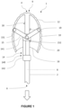
- FIG. 1 illustrates a side view of a hemostatic device 1.
- the hemostatic device 1 comprises a hollow shaft 2 extending from a first end 4 to a second end 6.
- the hollow shaft 2 comprises an inner channel 8 configured to be fluidically connected to a vacuum source.
- the hemostatic device 1 advantageously comprises a base coupled to the second end 6 of the shaft 2 configured to connect to the vacuum source.
- the hemostatic device 1 comprises a plurality of hollow ribs 10, a first end 9 of each rib 10 being fixed to the first end 4 of the shaft 2.
- the ribs 10 can be fixed to the shaft 2 in several possible ways.
- the ribs 10 and the shaft 2 can be welded, tightly mounted, screwed or blocked by means of a third piece in the area of the first end 4 of the shaft 2 (like a nut system).
- the ribs 10 and the shaft 2 can be made in one single piece, for example by additive manufacturing, by injection manufacturing or by molding.
- the shaft 2 and the ribs 10 are made of a flexible biocompatible polymer such as polyethylene (PE), polypropylene (PP), polyurethane (PU), polyethylene terephthalate (PET).
- the shaft 2 is more rigid than the ribs 10.
- the hemostatic device 1 cannot bend too much so as to be easily inserted into a body cavity.
- the ribs 10 can be more flexible so as to be able to deform and fit the walls of a natural body cavity. Consequently, the ribs 10 can be made of a flexible biocompatible polymer which is even more flexible than the polymers already cited, such as thermoplastic elastomers (TPE) or thermoplastic polyurethane (TPU).
- TPE thermoplastic elastomers
- TPU thermoplastic polyurethane
- the hemostatic device 1 comprises between four and twelve ribs 10.
- the hemostatic device 1 comprises at least three ribs 10 which are spaced from each other by a same angle. It can be understood here that the first ends 9 of the ribs 10 are fixed to the first end 4 of the shaft 2 in a constant pattern so that the angles between adjacent ribs 10 are equal.
- the hemostatic device 1 can be seen as having the shape of an umbrella and it is understood that each rib 10 is adjacent to two other ribs 10.
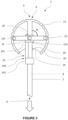
- FIG. 2 illustrates a sectional view of the hemostatic device 1.
- Each rib 10 comprises an inner channel 11 fluidically connected to the inner channel 8 of the shaft 2.
- Each rib 10 also comprises a plurality of holes 12.
- the plurality of holes 12 lead to the inner channel 11 of the respective rib 10.
- the holes 12 lead to an inner channel 11 of a rib 10, the inner channel 11 of the rib 10 leading to the inner channel 8 of the shaft 2.
- each rib 10 preferably comprises a plurality of holes 12.
- the plurality of holes 12 of each rib 10 are arranged so as to face the bleeding area to induce a negative pressure in the natural body cavity when a negative pressure is applied by the vacuum source, the induced negative pressure being configured so that the wall of the natural body cavity is attracted to the ribs 10.
- the plurality of holes 12 in each rib 10 are arranged in a constant pattern.
- the holes 12 are equidistant.
- the holes 12 can be regularly, in an equidistant manner, arranged along each rib 10.
- the distance between the holes 12 of the ribs 10 can range from 1 mm to 20 mm.
- the diameter of the holes 12 of the ribs 10 ranges from 0,5 mm to 5 mm.
- the hemostatic device 1 comprises a membrane 16 extending between the ribs 10 and configured to be placed so as to face, at least partially, a bleeding area of a natural body cavity.
- the natural body cavity is a uterus.
- the membrane 16 covers the ribs 10.
- the membrane 16 is made of a single piece and does not comprise a plurality of pieces of membrane 160.
- the membrane 16 comprises membrane holes 13 facing the holes 12 of the ribs 10 so that the holes 12 of the ribs 10 are not sealed. Consequently, the vacuum can be applied into a body cavity via the holes 12.
- the diameter of the membrane holes 13 can be equal to the diameter of the holes 12 of the ribs 10. In another embodiment, the diameter of the membrane holes 13 can be greater than the diameter of the holes 12 of the ribs 10 so that it is easier to place the membrane 16 on the ribs 10 without the membrane 16 blocking the holes 12 of the ribs 10.
- the membrane 16 can be fixed to the ribs 10 in several ways.
- the membrane 16 can be stitched or welded to the ribs 10.
- the membrane 16 can also be fixed to the ribs 10 thanks to mechanical connections.
- the ribs 10 can comprise notches thanks to which the membrane 16 is fixed to the ribs 10.
- the membrane 16 can comprise a plurality of pieces of membrane 160, each piece of membrane 160 extending from a first rib 10 to a second rib 10 which is adjacent to the first rib 10. Each piece of membrane 160 thus extends between a respective pair of adjacent ribs 10.
- the membrane 16 is preferably made of waterproof fabric or of an elastomer.
- the membrane 16 can be made of woven or knitted textile with waterproof coating or can be an electrospun membrane with waterproof coating.
- the membrane 16 can be made by silicone molding or by thermoplastic elastomer (TPE) injection molding.
- the thickness of the membrane 16 ranges preferably from 0,1 mm to 10 mm.
- the hemostatic device 1 comprises a mechanism 14 configured to move the ribs 10 relative to the shaft 2.
- the mechanism 14 preferably comprises a sliding assembly 140 slidable along the shaft 2 and a plurality of connecting rods 15.
- the sliding assembly 140 comprises a first sliding ring 141 connected to the connecting rods 15, each connecting rod 15 being, on the opposite end, connected to a respective rib 10.
- the connecting rods 15 are connected to the ribs 10 by first pivot pins 151.
- the connecting rods 15 are connected to the first sliding ring 141 by second pivot pins 152.
- the sliding assembly 140 comprises a second sliding ring 142 arranged to remain outside the natural cavity when the hemostatic device 1 is in use.
- the second sliding ring 142 is further away from the first end 4 of the shaft 2 than the first sliding ring 141.
- the first sliding ring 141 is closer to the first end 4 of the shaft 2 than the second sliding ring 142.
- the first sliding ring 141 and the second sliding ring 142 are rigidly connected so that the mechanism 14 is operable by moving the second sliding ring 142.
- the sliding assembly 140 can be made of one piece.
- the sliding assembly 140 is made of conventional polymers such as PE / PP / PET or polymers which are optimized to reduce friction, such as ePTFE (Expanded Polytetrafluoroethylene).
- the shaft 2 comprises a first stop 18 configured to stop the sliding of the sliding assembly 140 towards the first end 4 of the shaft 2.
- the hemostatic device comprises a second stop 19 configured to reversibly lock the ribs 10 in a maximum expanded position.
- the ribs of the hemostatic device illustrated are in an expanded position.
- the second stop prevents the sliding of the sliding assembly 140 towards the second end 6 of the shaft 2 once the ribs are in said maximum expanded position.
- the second stop 19 may present an abutment surface extending radially from the shaft 2 and an inclined surface tapering from the abutment surface to the shaft.
- reversibly it is meant that the locking is temporary.
- the sliding assembly 140 is allowed to slide back to the second end 6 of the shaft 2 to bring the ribs to their retracted position if the second stop 19 is overcome which can be done in various ways.
- the second stop 19 can be configured to enter in a slot made in the shaft 2 once a button is pressed or if a certain force is applied to the second stop 19.
- the hemostatic device 1 comprises a third stop 20 configured to reversibly lock the ribs 10 in an intermediate expanded position. It is understood that the third stop 20 is closer to the second end 6 of the shaft 2 than the second stop 19 is.
- the third stop 20 can be similar to the second stop 19.
- the hemostatic device 1 comprises a fourth stop 21 as illustrated in FIG. 2 .
- the fourth stop 21 is configured to limit the movement of the sliding assembly 140 towards the second end 6. More particularly, the fourth stop 21 is configured to prevent the sliding assembly 140 to be taken apart from the shaft 2 when the sliding assembly 140 moves towards the second end 6.
- step S1 the hemostatic device 1 is prepared by the medical staff.
- the preparation includes in particular unpacking the hemostatic device 1 from its package and connecting the inner channel 8 of the shaft 2 to the vacuum source.
- step S2 the hemostatic device 1 is inserted into the natural body cavity, for example the uterus.
- the ribs 10 are in a retracted position allowing the insertion of the hemostatic device 1 into the natural body cavity (and thus, obviously, allowing the extraction once that the bleeding has been stopped).
- FIG. 5 illustrates the hemostatic device 1 wherein the ribs 10 are in a retracted position.
- the angle between the connecting rods 15 and the shaft 2 is a.
- step S3 the sliding assembly 140 of the mechanism 14 is slid towards the first end 4 of the shaft 2 so that the mechanism 14 moves the ribs 10 relative to the shaft 2 towards an expanded position wherein the membrane 16 and the ribs 10 substantially fit the natural body cavity.
- fit the natural body cavity it is meant that the membrane 16 and the ribs 10 substantially fit the shape and the size of the natural body cavity.
- substantially fit it is meant that according to the size of the natural body cavity, the membrane 16 and the ribs 10 may not perfectly fit the internal wall of the natural body cavity, i.e. that the entire surfaces of the membrane 16 and of the ribs 10 may not be in contact with the internal wall of the natural body cavity.
- the membrane and the ribs generally contact more than 50% of the surface of the natural body cavity, preferably more than 80% of the surface of the natural body cavity.
- the size and shape of the uterus may vary for every woman but providing that the membrane 16 and the ribs 10 substantially fit the natural body cavity allows maintaining the effectiveness of the hemostatic device regardless of such variations in size and shape.
- the membrane 16 and the ribs 10 face, at least partially, a bleeding area of the natural body cavity.
- the second sliding ring 142 is slid by the medical staff towards the first end 4 of the shaft 2. Consequently, the sliding assembly 140, i.e. the first sliding ring 141, the second sliding ring 142 and the rigid connection between the rings, is slid. Hence, the connecting rods 15 move and make the ribs 10 move to the expanded position.
- the sliding assembly 140 is slid to the first stop 18 so that the ribs 10 are in the maximum expanded position.
- the angle between the connecting rods 15 and the shaft 2 is comprised between 90° and 100°. In other terms, as illustrated in FIG. 3 , the angle ⁇ is greater than or equal to 90°.
- the maximum expanded position corresponds to a position wherein the ribs 10 and, thus, the membrane 16, fit the wall of the natural body cavity. Further, the sliding of the sliding assembly 140 is stopped by the second stop 19 so that it is not necessary for the medical staff to maintain the second sliding ring 142 in a certain position.
- the hemostatic device 1 is adapted to several types of natural body cavities.
- one same hemostatic device 1 can be adapted to a uterus and to a bladder.
- the hemostatic device 1 can be adapted to natural body cavities which do not have the same size. Consequently, in this case, the sliding assembly 140 can be slid until the ribs are in an intermediate expanded position.
- the sliding assembly 140 is slid until the first sliding ring 141 has overtaken the third stop 20.
- the angle between the connecting rods 15 and the shaft 2 is higher than 45° and lower than 90°.
- FIG.1 shows the hemostatic device 1 when the ribs 10 are in an intermediate expanded position.
- the sliding assembly 140 is stopped so that it is not necessary for the medical staff to maintain the second sliding ring 142 in a certain position.
- the second stop 19 and the third stop 20 have the same role but the second stop 19 is configured to stop the sliding of the sliding assembly 140 when the sliding assembly 140 is closer to the first end 4 of the shaft 2 than the sliding assembly 140 when it is stopped by the third stop 20.
- the third stop 20 can also be seen as a safety in the case the second stop 19 is deficient.
- step S4 the vacuum source is turned on so that a depression is applied into the natural body cavity.
- the inner channel 8 of the shaft 2 is fluidically connected to the inner channels 11 of the ribs 10, the inner channels 11 of the ribs 10 being fluidically connected to the natural body cavity through the holes 12 of the ribs 10.
- FIG. 6 schematically illustrates the circulation of the vacuum into the hemostatic device 1. As a result, the wall of the natural body cavity is attracted by the ribs 10.
- the level of vacuum applied i.e. the negative pressure applied in the natural body cavity
- the level of vacuum applied depends on the clinical case.
- a low negative pressure is sufficient, for example a negative pressure of 10 mbar.
- an important negative pressure is necessary, for example a negative pressure of 1000 mbar.
- Step S5 is a first stabilization step, in which the vacuum is maintained. Hemostasis is initiated by a dual action of the hemostatic device: (1) direct contact between the wall of the natural body cavity and the ribs 10 and the membrane 16 of the hemostatic device 1 (promoting a so-called "contact hemostasis") and (2) compression of the wall of the natural body cavity and its internal structure by aspiration. Thanks to the fact that the holes 12 of the ribs are arranged in a constant pattern, the vacuum distribution is homogeneous.
- step S6 the medical staff slides the second sliding ring 142 toward the second end 6 of the shaft 2 so that the sliding assembly 140 slides towards the second end 6 of the shaft 2. Consequently, the ribs 10 of the hemostatic device 1 are gradually retracted.
- the sliding assembly 140 can be slid until the third stop 20 so that the ribs 10 are in the intermediate position. Then, the sliding assembly 140 can be slid until the ribs 10 reach the retracted position.
- the third stop 20 allows to retract the ribs 10 gradually.
- the ribs 1 are in the retracted position.
- the natural body cavity size decreases, and a negative pressure may be maintained by the vacuum source. The reduction of the size of the natural body cavity promotes the contraction of the muscles. These contractions compress the vessels and stop the bleeding permanently.
- Step 6 is performed manually by the medical staff. It is reminded that, before step 6, the sliding assembly 140 is normally stopped by the second stop 19 or the third stop 20. In order to free the sliding assembly 140, the medical staff can pull the sliding assembly 140 towards the second end 6 of the shaft and applying a force higher enough to make the sliding assembly 140 overtake the second stop 19 or the third stop 20. In another embodiment, the medical staff can press a button which make the stops 19, 20 deactivated. The man skilled in the art knows types of stops described and methods to use them.
- step 6 can be triggered by the natural body cavity itself. Indeed, if the uterus contracts again, the wall of the uterus applies a force on the ribs 10 of the hemostatic device 1. The force can be strong enough to make the sliding assembly 140 overtake the second stop 19 or the third stop 20 without any manual intervention.
- step S7 the negative pressure is stopped, i.e. the vacuum source is turned off.
- step S8 the hemostatic device 1 is extracted from the natural body cavity, and the medical procedure ends, after a minimal treatment time of 10 minutes for example, depending on the specific protocol.
Abstract
Description
- The present disclosure relates to a hemostatic device, in particular intended to stop or reduce hemorrhages in a natural body cavity such as a uterus.
- After childbirth, the mother's uterus is generally subjected to contractions that allow to stop the bleeding caused by the detachment of the placenta.
- However, in some cases, the uterus may suffer from atony, so that such contractions do not occur or are not sufficient to stop the bleeding, thereby generating a risk of maternal hemorrhage.
- Various hemostatic devices have been developed to promote the contraction of the uterus and help stopping or reducing the hemorrhage.
- Document
EP 3 248 624 teaches a hemostatic device for treating postpartum hemorrhage, comprising a flat flexible plate presenting a pair of opposite faces configured to be placed in contact with a wall of the uterus and an empty internal volume in fluidic connection with a vacuum pump. Each face comprises a plurality of holes such that when a negative pressure is created in the internal volume by the pump, the walls of the uterus are attracted by the respective face of the plate and held together, which mechanically shrinks the uterus, thereby compacting the muscles forming the wall of the uterus and constricting the blood vessels to stop bleeding. However, the size of the uterus may vary from one patient to another one. It may be difficult to introduce the hemostatic device in a little uterus like a partially retracted uterus. It may thus be necessary to provide different formats of the hemostatic device to allow the practitioner to select the one fitting best the patient's uterus. In addition, the size of the uterus also decreases as the uterus contracts. Thus, once the uterus has attained the size of the flexible plate, the hemostatic device may hinder further contraction of the uterus. - Document
WO 2020/123525 teaches a hemostatic device for treating postpartum hemorrhage, comprising a flexible portion configured to be inserted into the uterus, a seal configured to close the opening of the uterus, and a vacuum pump in fluidic connection with holes provided in the flexible portion. When the uterus is sealed, the pump creates a negative pressure within the uterus via the holes in order to facilitate contractile movement of the uterine wall and vessel constriction. In this device, various means may be provided to protect the holes from occlusion by tissues. Because of the shape of this hemostatic device, when it is in a uterus, the area of the uterine wall which is in contact with the hemostatic device is limited. Consequently, the hemostatic effect of the contact between the hemostatic device and a bleeding area of the uterus is limited. Moreover, the space remaining between the uterine wall and the hemostatic device allows the vacuum to escape from the neck of the uterus. In order to reduce this depression, an inflatable balloon is required which makes the hemostatic device complicated to use. Furthermore, the pressure applied in the area of the neck of the uterus can be excessive as the area of the neck of uterus is fragile and not very extensible. - There remains a need for a hemostatic device that can be easily inserted into a natural body cavity such as the uterus and conform to the shape of the cavity, while providing an efficient stimulation of the muscles forming the wall of the cavity and constriction of the blood vessels, without hindering further contraction of the uterus over time.
- Some embodiments relate to a hemostatic device comprising:
- a hollow shaft extending from a first end to a second end, the shaft comprising an inner channel configured to be fluidically connected to a vacuum source,
- a plurality of hollow ribs, a first end of each rib being fixed to the first end of the shaft, each rib comprising an inner channel fluidically connected to the inner channel of the shaft and a plurality of holes leading to the inner channel of the respective rib,
- a membrane extending between the ribs and configured to be placed so as to face, at least partially, a bleeding area of a natural body cavity,
the plurality of holes of each rib being arranged so as to face the bleeding area to induce a negative pressure in the natural body cavity when a negative pressure is applied by the vacuum source, the induced negative pressure being configured so that the wall of the natural cavity is attracted to the ribs, and - a mechanism configured to move the ribs relative to the shaft between a retracted position allowing insertion and extraction of the hemostatic device into the natural cavity and an expanded position wherein the membrane and the ribs substantially fit the natural cavity.
- According to advantageous and non-limiting features, taken alone or in any combination:
The membrane covers the ribs and comprises membrane holes placed so as to face the holes of the ribs. - The mechanism comprises a sliding assembly slidable along the shaft, the sliding assembly comprising a first sliding ring connected to a plurality of connecting rods, each connecting rod being connected to a respective rib, so that, when the first sliding ring is slid towards the first end of the shaft, the connecting rods make the ribs move to the expanded position.
- The connecting rods are connected to the ribs by first pivot pins.
- The connecting rods are connected to the first sliding ring by second pivot pins.
- When the ribs are in the retracted position, the angle between the connecting rods and the shaft is lower than 45°.
- The sliding assembly comprises a second sliding ring arranged to remain outside the natural cavity, the first sliding ring being closer to the first end of the shaft than the second sliding ring, the first sliding ring and the second sliding ring being rigidly connected so that the mechanism is operable by moving the second sliding ring.
- The shaft comprises a first stop configured to stop the sliding of the sliding assembly towards the first end of the shaft.
- The shaft comprises a second stop configured to reversibly stop the sliding of the sliding assembly towards the second end of the shaft when the ribs are in a maximum expanded position.
- When the ribs are in a maximum expanded position, the angle between the connecting rods and the shaft is comprised between 90° and 100°.
- The shaft comprises a third stop configured to reversibly stop the sliding of the sliding assembly towards the second end of the shaft when the ribs are in an intermediate expanded position and, when the ribs are in the intermediate maximum expanded position, the angle between the connecting rods and the shaft is higher than 45° and lower than 90°.
- The holes in each rib are arranged in a constant pattern.
- The hemostatic device comprises at least three ribs, the ribs being spaced from each other by a same angle.
- The shaft is made of a rigid biocompatible polymer and the ribs are made of a flexible biocompatible polymer.
- The membrane is made of a waterproof fabric or of an elastomer.
- Further features and advantages will be described in the following description, based on the appended drawings, in which:
-
FIG. 1 is a side view of a hemostatic device; -
FIG. 2 is a sectional view of the hemostatic device; -
FIG. 3 is a side view of the hemostatic device when the ribs of the hemostatic device are in an expanded position; -
FIG. 4 schematically illustrates successive steps of operation of the hemostatic device; -
FIG. 5 is a side view of the hemostatic device when the ribs of the hemostatic device are in a retracted position; -
FIG. 6 schematically illustrates the circulation of the vacuum into the hemostatic device. - For sake of legibility of the drawings, some components of the hemostatic device may have been omitted. In addition, the drawings are not necessarily drawn to scale.
- In the drawings, identical reference signs designate elements that are identical to each other or that fulfil the same function. Thus, when one element has been described in detail with reference to one figure, it may not be described in detail again with reference to another figure.
- The invention relates to a hemostatic device configured to be inserted into a natural body cavity, such as a uterus, comprising a bleeding area.
- The hemostatic device can have at least two positions comprising an expanded position and a retracted position.
- The hemostatic device can be inserted into the natural body cavity in the retracted position; then it is expanded to substantially fit the natural body cavity. The wall of the natural body cavity is attracted to the hemostatic device due to the negative pressure induced in the natural body cavity by a vacuum circuit arranged in the hemostatic device, which causes bleeding to stop. The hemostatic device can be moved back to the retracted position to be extracted from the natural body cavity.
-
FIG. 1 illustrates a side view of ahemostatic device 1. Thehemostatic device 1 comprises ahollow shaft 2 extending from afirst end 4 to asecond end 6. Thehollow shaft 2 comprises aninner channel 8 configured to be fluidically connected to a vacuum source. To allow connecting theinner channel 8 of theshaft 2 to the vacuum source, thehemostatic device 1 advantageously comprises a base coupled to thesecond end 6 of theshaft 2 configured to connect to the vacuum source. - The
hemostatic device 1 comprises a plurality ofhollow ribs 10, afirst end 9 of eachrib 10 being fixed to thefirst end 4 of theshaft 2. Theribs 10 can be fixed to theshaft 2 in several possible ways. In some embodiments, theribs 10 and theshaft 2 can be welded, tightly mounted, screwed or blocked by means of a third piece in the area of thefirst end 4 of the shaft 2 (like a nut system). In more preferred embodiments, theribs 10 and theshaft 2 can be made in one single piece, for example by additive manufacturing, by injection manufacturing or by molding. Preferably, theshaft 2 and theribs 10 are made of a flexible biocompatible polymer such as polyethylene (PE), polypropylene (PP), polyurethane (PU), polyethylene terephthalate (PET). In a preferred embodiment, theshaft 2 is more rigid than theribs 10. Indeed, it is preferable that thehemostatic device 1 cannot bend too much so as to be easily inserted into a body cavity. However, theribs 10 can be more flexible so as to be able to deform and fit the walls of a natural body cavity. Consequently, theribs 10 can be made of a flexible biocompatible polymer which is even more flexible than the polymers already cited, such as thermoplastic elastomers (TPE) or thermoplastic polyurethane (TPU). - Typically, the
hemostatic device 1 comprises between four and twelveribs 10. Preferably, thehemostatic device 1 comprises at least threeribs 10 which are spaced from each other by a same angle. It can be understood here that the first ends 9 of theribs 10 are fixed to thefirst end 4 of theshaft 2 in a constant pattern so that the angles betweenadjacent ribs 10 are equal. Thehemostatic device 1 can be seen as having the shape of an umbrella and it is understood that eachrib 10 is adjacent to twoother ribs 10. -
FIG. 2 illustrates a sectional view of thehemostatic device 1. Eachrib 10 comprises aninner channel 11 fluidically connected to theinner channel 8 of theshaft 2. Eachrib 10 also comprises a plurality ofholes 12. The plurality ofholes 12 lead to theinner channel 11 of therespective rib 10. In other words, for each rib, theholes 12 lead to aninner channel 11 of arib 10, theinner channel 11 of therib 10 leading to theinner channel 8 of theshaft 2. It is understood that eachrib 10 preferably comprises a plurality ofholes 12. Thus, when vacuum is applied through theinner channel 8 of thehollow shaft 2, a negative pressure is created through theinner channels 11 of eachrib 10 to theholes 12. - The plurality of
holes 12 of eachrib 10 are arranged so as to face the bleeding area to induce a negative pressure in the natural body cavity when a negative pressure is applied by the vacuum source, the induced negative pressure being configured so that the wall of the natural body cavity is attracted to theribs 10. - Advantageously, the plurality of
holes 12 in eachrib 10 are arranged in a constant pattern. Preferably, in eachrib 10, theholes 12 are equidistant. For example, theholes 12 can be regularly, in an equidistant manner, arranged along eachrib 10. The distance between theholes 12 of theribs 10 can range from 1 mm to 20 mm. Also, the diameter of theholes 12 of theribs 10 ranges from 0,5 mm to 5 mm. - The
hemostatic device 1 comprises amembrane 16 extending between theribs 10 and configured to be placed so as to face, at least partially, a bleeding area of a natural body cavity. Preferably, the natural body cavity is a uterus. - In a first embodiment, the
membrane 16 covers theribs 10. In this embodiment, themembrane 16 is made of a single piece and does not comprise a plurality of pieces of membrane 160. Thus, themembrane 16 comprises membrane holes 13 facing theholes 12 of theribs 10 so that theholes 12 of theribs 10 are not sealed. Consequently, the vacuum can be applied into a body cavity via theholes 12. The diameter of the membrane holes 13 can be equal to the diameter of theholes 12 of theribs 10. In another embodiment, the diameter of the membrane holes 13 can be greater than the diameter of theholes 12 of theribs 10 so that it is easier to place themembrane 16 on theribs 10 without themembrane 16 blocking theholes 12 of theribs 10. - The
membrane 16 can be fixed to theribs 10 in several ways. For example, themembrane 16 can be stitched or welded to theribs 10. Themembrane 16 can also be fixed to theribs 10 thanks to mechanical connections. For example, theribs 10 can comprise notches thanks to which themembrane 16 is fixed to theribs 10. - In a second embodiment, the
membrane 16 can comprise a plurality of pieces of membrane 160, each piece of membrane 160 extending from afirst rib 10 to asecond rib 10 which is adjacent to thefirst rib 10. Each piece of membrane 160 thus extends between a respective pair ofadjacent ribs 10. - The
membrane 16 is preferably made of waterproof fabric or of an elastomer. For example, themembrane 16 can be made of woven or knitted textile with waterproof coating or can be an electrospun membrane with waterproof coating. In another example, themembrane 16 can be made by silicone molding or by thermoplastic elastomer (TPE) injection molding. - The thickness of the
membrane 16 ranges preferably from 0,1 mm to 10 mm. - The
hemostatic device 1 comprises amechanism 14 configured to move theribs 10 relative to theshaft 2. Themechanism 14 preferably comprises a slidingassembly 140 slidable along theshaft 2 and a plurality of connectingrods 15. The slidingassembly 140 comprises a first slidingring 141 connected to the connectingrods 15, each connectingrod 15 being, on the opposite end, connected to arespective rib 10. Preferably, the connectingrods 15 are connected to theribs 10 by first pivot pins 151. Also, preferably, the connectingrods 15 are connected to the first slidingring 141 by second pivot pins 152. - Preferably, the sliding
assembly 140 comprises a second slidingring 142 arranged to remain outside the natural cavity when thehemostatic device 1 is in use. The second slidingring 142 is further away from thefirst end 4 of theshaft 2 than the first slidingring 141. In other words, the first slidingring 141 is closer to thefirst end 4 of theshaft 2 than the second slidingring 142. The first slidingring 141 and the second slidingring 142 are rigidly connected so that themechanism 14 is operable by moving the second slidingring 142. In a certain embodiment, the slidingassembly 140 can be made of one piece. The slidingassembly 140 is made of conventional polymers such as PE / PP / PET or polymers which are optimized to reduce friction, such as ePTFE (Expanded Polytetrafluoroethylene). - In a preferred embodiment, the
shaft 2 comprises afirst stop 18 configured to stop the sliding of the slidingassembly 140 towards thefirst end 4 of theshaft 2. - Further, preferably, the hemostatic device comprises a
second stop 19 configured to reversibly lock theribs 10 in a maximum expanded position. InFIG. 3 , the ribs of the hemostatic device illustrated are in an expanded position. To that end, the second stop prevents the sliding of the slidingassembly 140 towards thesecond end 6 of theshaft 2 once the ribs are in said maximum expanded position. For example, thesecond stop 19 may present an abutment surface extending radially from theshaft 2 and an inclined surface tapering from the abutment surface to the shaft. By "reversibly", it is meant that the locking is temporary. As a result, the slidingassembly 140 is allowed to slide back to thesecond end 6 of theshaft 2 to bring the ribs to their retracted position if thesecond stop 19 is overcome which can be done in various ways. For example, thesecond stop 19 can be configured to enter in a slot made in theshaft 2 once a button is pressed or if a certain force is applied to thesecond stop 19. - In a certain embodiment, the
hemostatic device 1 comprises athird stop 20 configured to reversibly lock theribs 10 in an intermediate expanded position. It is understood that thethird stop 20 is closer to thesecond end 6 of theshaft 2 than thesecond stop 19 is. Thethird stop 20 can be similar to thesecond stop 19. - In a certain embodiment, the
hemostatic device 1 comprises afourth stop 21 as illustrated inFIG. 2 . Thefourth stop 21 is configured to limit the movement of the slidingassembly 140 towards thesecond end 6. More particularly, thefourth stop 21 is configured to prevent the slidingassembly 140 to be taken apart from theshaft 2 when the slidingassembly 140 moves towards thesecond end 6. - A complete workflow of a treatment using the
hemostatic device 1 will be described with reference toFIG. 4 . - In step S1, the
hemostatic device 1 is prepared by the medical staff. The preparation includes in particular unpacking thehemostatic device 1 from its package and connecting theinner channel 8 of theshaft 2 to the vacuum source. - In step S2, the
hemostatic device 1 is inserted into the natural body cavity, for example the uterus. When thehemostatic device 1 is inserted into the natural body cavity, theribs 10 are in a retracted position allowing the insertion of thehemostatic device 1 into the natural body cavity (and thus, obviously, allowing the extraction once that the bleeding has been stopped). - More precisely, when the
ribs 10 are in the retracted position, the angle between the connectingrods 15 and theshaft 2 is lower than 45°.FIG. 5 illustrates thehemostatic device 1 wherein theribs 10 are in a retracted position. InFIG. 5 , the angle between the connectingrods 15 and theshaft 2 is a. - In step S3, the sliding
assembly 140 of themechanism 14 is slid towards thefirst end 4 of theshaft 2 so that themechanism 14 moves theribs 10 relative to theshaft 2 towards an expanded position wherein themembrane 16 and theribs 10 substantially fit the natural body cavity. By "fit the natural body cavity", it is meant that themembrane 16 and theribs 10 substantially fit the shape and the size of the natural body cavity. By "substantially fit", it is meant that according to the size of the natural body cavity, themembrane 16 and theribs 10 may not perfectly fit the internal wall of the natural body cavity, i.e. that the entire surfaces of themembrane 16 and of theribs 10 may not be in contact with the internal wall of the natural body cavity. However, when the hemostatic device is in the expanded position and vacuum is applied though the holes of the ribs, the membrane and the ribs generally contact more than 50% of the surface of the natural body cavity, preferably more than 80% of the surface of the natural body cavity. Indeed, for example, the size and shape of the uterus may vary for every woman but providing that themembrane 16 and theribs 10 substantially fit the natural body cavity allows maintaining the effectiveness of the hemostatic device regardless of such variations in size and shape. At the end of the step S3, themembrane 16 and theribs 10 face, at least partially, a bleeding area of the natural body cavity. - More precisely, the second sliding
ring 142 is slid by the medical staff towards thefirst end 4 of theshaft 2. Consequently, the slidingassembly 140, i.e. the first slidingring 141, the second slidingring 142 and the rigid connection between the rings, is slid. Hence, the connectingrods 15 move and make theribs 10 move to the expanded position. - Generally, the sliding
assembly 140 is slid to thefirst stop 18 so that theribs 10 are in the maximum expanded position. Preferably, when theribs 10 are in the maximum expanded position, the angle between the connectingrods 15 and theshaft 2 is comprised between 90° and 100°. In other terms, as illustrated inFIG. 3 , the angle α is greater than or equal to 90°. Preferably, the maximum expanded position corresponds to a position wherein theribs 10 and, thus, themembrane 16, fit the wall of the natural body cavity. Further, the sliding of the slidingassembly 140 is stopped by thesecond stop 19 so that it is not necessary for the medical staff to maintain the second slidingring 142 in a certain position. - In a certain embodiment, the
hemostatic device 1 is adapted to several types of natural body cavities. For example, onesame hemostatic device 1 can be adapted to a uterus and to a bladder. Thus, thehemostatic device 1 can be adapted to natural body cavities which do not have the same size. Consequently, in this case, the slidingassembly 140 can be slid until the ribs are in an intermediate expanded position. Thus, the slidingassembly 140 is slid until the first slidingring 141 has overtaken thethird stop 20. When theribs 10 are in the intermediate expanded position, the angle between the connectingrods 15 and theshaft 2 is higher than 45° and lower than 90°.FIG.1 shows thehemostatic device 1 when theribs 10 are in an intermediate expanded position. - Thanks to the
second stop 19 or thethird stop 20, the slidingassembly 140 is stopped so that it is not necessary for the medical staff to maintain the second slidingring 142 in a certain position. It is understood here that thesecond stop 19 and thethird stop 20 have the same role but thesecond stop 19 is configured to stop the sliding of the slidingassembly 140 when the slidingassembly 140 is closer to thefirst end 4 of theshaft 2 than the slidingassembly 140 when it is stopped by thethird stop 20. Thethird stop 20 can also be seen as a safety in the case thesecond stop 19 is deficient. - In step S4, the vacuum source is turned on so that a depression is applied into the natural body cavity. Indeed, it is reminded that the
inner channel 8 of theshaft 2 is fluidically connected to theinner channels 11 of theribs 10, theinner channels 11 of theribs 10 being fluidically connected to the natural body cavity through theholes 12 of theribs 10.FIG. 6 schematically illustrates the circulation of the vacuum into thehemostatic device 1. As a result, the wall of the natural body cavity is attracted by theribs 10. - The level of vacuum applied, i.e. the negative pressure applied in the natural body cavity, depends on the clinical case. In the case of a uterus, if the uterus is capable of contracting again quite autonomously, it only needs to be incited to contract again and a low negative pressure is sufficient, for example a negative pressure of 10 mbar. However, if the uterus is lifeless, an important negative pressure is necessary, for example a negative pressure of 1000 mbar.
- Step S5 is a first stabilization step, in which the vacuum is maintained. Hemostasis is initiated by a dual action of the hemostatic device: (1) direct contact between the wall of the natural body cavity and the
ribs 10 and themembrane 16 of the hemostatic device 1 (promoting a so-called "contact hemostasis") and (2) compression of the wall of the natural body cavity and its internal structure by aspiration. Thanks to the fact that theholes 12 of the ribs are arranged in a constant pattern, the vacuum distribution is homogeneous. - In step S6, the medical staff slides the second sliding
ring 142 toward thesecond end 6 of theshaft 2 so that the slidingassembly 140 slides towards thesecond end 6 of theshaft 2. Consequently, theribs 10 of thehemostatic device 1 are gradually retracted. Firstly, the slidingassembly 140 can be slid until thethird stop 20 so that theribs 10 are in the intermediate position. Then, the slidingassembly 140 can be slid until theribs 10 reach the retracted position. Thus, thethird stop 20 allows to retract theribs 10 gradually. At the end of said step (seeFIG. 5 ), theribs 1 are in the retracted position. During said step, the natural body cavity size decreases, and a negative pressure may be maintained by the vacuum source. The reduction of the size of the natural body cavity promotes the contraction of the muscles. These contractions compress the vessels and stop the bleeding permanently. -
Step 6 is performed manually by the medical staff. It is reminded that, beforestep 6, the slidingassembly 140 is normally stopped by thesecond stop 19 or thethird stop 20. In order to free the slidingassembly 140, the medical staff can pull the slidingassembly 140 towards thesecond end 6 of the shaft and applying a force higher enough to make the slidingassembly 140 overtake thesecond stop 19 or thethird stop 20. In another embodiment, the medical staff can press a button which make thestops - In a possible embodiment,
step 6 can be triggered by the natural body cavity itself. Indeed, if the uterus contracts again, the wall of the uterus applies a force on theribs 10 of thehemostatic device 1. The force can be strong enough to make the slidingassembly 140 overtake thesecond stop 19 or thethird stop 20 without any manual intervention. - In step S7, the negative pressure is stopped, i.e. the vacuum source is turned off.
- In step S8, the
hemostatic device 1 is extracted from the natural body cavity, and the medical procedure ends, after a minimal treatment time of 10 minutes for example, depending on the specific protocol.
Claims (15)
- Hemostatic device (1) comprising:- a hollow shaft (2) extending from a first end (4) to a second end (6), the shaft (2) comprising an inner channel (8) configured to be fluidically connected to a vacuum source,- a plurality of hollow ribs (10), a first end (9) of each rib (10) being fixed to the first end (4) of the shaft (2), each rib (10) comprising an inner channel (11) fluidically connected to the inner channel (8) of the shaft (2) and a plurality of holes (12) leading to the inner channel (11) of the respective rib (10),- a membrane (16) extending between the ribs (10) and configured to be placed so as to face, at least partially, a bleeding area of a natural body cavity,
the plurality of holes (12) of each rib (10) being arranged so as to face the bleeding area to induce a negative pressure in the natural body cavity when a negative pressure is applied by the vacuum source, the induced negative pressure being configured so that the wall of the natural cavity is attracted to the ribs (10), and- a mechanism (14) configured to move the ribs (10) relative to the shaft (2) between a retracted position allowing insertion and extraction of the hemostatic device (1) into the natural cavity and an expanded position wherein the membrane (16) and the ribs (10) substantially fit the natural cavity. - Hemostatic device (1) according to claim 1, wherein the membrane (16) covers the ribs (10) and comprises membrane holes (13) placed so as to face the holes (12) of the ribs (10).
- Hemostatic device (1) according to any one of claims 1 or 2, wherein the mechanism (14) comprises a sliding assembly (140) slidable along the shaft (2), the sliding assembly (140) comprising a first sliding ring (141) connected to a plurality of connecting rods (15), each connecting rod (15) being connected to a respective rib (10), so that, when the first sliding ring (141) is slid towards the first end (4) of the shaft (2), the connecting rods (15) make the ribs (10) move to the expanded position.
- Hemostatic device (1) according to claim 3, wherein the connecting rods (15) are connected to the ribs (10) by first pivot pins (151).
- Hemostatic device (1) according to one of claims 3 or 4, wherein the connecting rods (15) are connected to the first sliding ring (141) by second pivot pins (152).
- Hemostatic device (1) according to any one of claims 3 to 5, wherein, when the ribs (10) are in the retracted position, the angle (α) between the connecting rods (15) and the shaft (2) is lower than 45°.
- Hemostatic device (1) according to any one of claims 3 to 6, wherein the sliding assembly (140) comprises a second sliding ring (142) arranged to remain outside the natural cavity, the first sliding ring (141) being closer to the first end (4) of the shaft (2) than the second sliding ring (142), the first sliding ring (141) and the second sliding ring (142) being rigidly connected so that the mechanism (14) is operable by moving the second sliding ring (142).
- Hemostatic device (1) according to any one of claims 3 to 7, wherein the shaft (2) comprises a first stop (18) configured to stop the sliding of the sliding assembly (140) towards the first end (4) of the shaft (2).
- Hemostatic device (1) according to any one of claims 3 to 8, wherein the shaft (2) comprises a second stop (19) configured to reversibly stop the sliding of the sliding assembly (140) towards the second end (6) of the shaft (2) when the ribs (10) are in a maximum expanded position.
- Hemostatic device (1) according to claim 9, wherein when the ribs (10) are in a maximum expanded position, the angle between the connecting rods (15) and the shaft (2) is comprised between 90° and 100°.
- Hemostatic device (1) according to any one of claims 1 to 10, wherein the shaft (2) comprises a third stop (20) configured to reversibly stop the sliding of the sliding assembly (140) towards the second end (6) of the shaft (2) when the ribs (10) are in an intermediate expanded position and, when the ribs (10) are in the intermediate maximum expanded position, the angle between the connecting rods (15) and the shaft (2) is higher than 45° and lower than 90°.
- Hemostatic device (1) according to any one of claims 1 to 11, wherein the holes (12) in each rib (10) are arranged in a constant pattern.
- Hemostatic device (1) according to any one of claims 1 to 12, comprising at least three ribs (10), the ribs (10) being spaced from each other by a same angle.
- Hemostatic device (1) according to any one of claims 1 to 13, wherein the shaft is made of a rigid biocompatible polymer and the ribs (10) are made of a flexible biocompatible polymer.
- Hemostatic device (1) according to any one of claims 1 to 14, wherein the membrane (16) is made of a waterproof fabric or of an elastomer.
Priority Applications (2)
| Application Number | Priority Date | Filing Date | Title |
|---|---|---|---|
| EP22305266.3A EP4241707A1 (en) | 2022-03-09 | 2022-03-09 | Hemostatic device |
| PCT/EP2023/055803 WO2023170101A1 (en) | 2022-03-09 | 2023-03-07 | Hemostatic device |
Applications Claiming Priority (1)
| Application Number | Priority Date | Filing Date | Title |
|---|---|---|---|
| EP22305266.3A EP4241707A1 (en) | 2022-03-09 | 2022-03-09 | Hemostatic device |
Publications (1)
| Publication Number | Publication Date |
|---|---|
| EP4241707A1 true EP4241707A1 (en) | 2023-09-13 |
Family
ID=80930399
Family Applications (1)
| Application Number | Title | Priority Date | Filing Date |
|---|---|---|---|
| EP22305266.3A Pending EP4241707A1 (en) | 2022-03-09 | 2022-03-09 | Hemostatic device |
Country Status (2)
| Country | Link |
|---|---|
| EP (1) | EP4241707A1 (en) |
| WO (1) | WO2023170101A1 (en) |
Citations (7)
| Publication number | Priority date | Publication date | Assignee | Title |
|---|---|---|---|---|
| SU1431746A1 (en) * | 1985-08-07 | 1988-10-23 | Ворошиловградский Медицинский Институт | Arrangement for stopping postpartum hemorrhages |
| EP3248624A1 (en) | 2010-07-13 | 2017-11-29 | Université Grenoble Alpes | Device for monitoring a blood flow occurring in a haemorrhagic region |
| WO2020123525A1 (en) | 2018-12-10 | 2020-06-18 | Alydia Health, Inc. | Postpartum uterine hemorrhage device |
| US20200352602A1 (en) * | 2012-03-15 | 2020-11-12 | Alydia Health, Inc. | Uterine hemorrhage controlling system and method |
| CN111248965B (en) * | 2020-02-04 | 2021-01-05 | 海雅美生物技术(珠海)有限公司 | Uterine cavity compression type hemostasis device for obstetrical department |
| US20210068865A1 (en) * | 2019-09-11 | 2021-03-11 | Noleus Technologies, Inc. | Apparatuses and methods for improving recovery from minimally invasive surgery |
| CN214907600U (en) * | 2021-05-18 | 2021-11-30 | 湄潭县人民医院 | Hemostatic bag for obstetrics and gynecology department |
-
2022
- 2022-03-09 EP EP22305266.3A patent/EP4241707A1/en active Pending
-
2023
- 2023-03-07 WO PCT/EP2023/055803 patent/WO2023170101A1/en unknown
Patent Citations (8)
| Publication number | Priority date | Publication date | Assignee | Title |
|---|---|---|---|---|
| SU1431746A1 (en) * | 1985-08-07 | 1988-10-23 | Ворошиловградский Медицинский Институт | Arrangement for stopping postpartum hemorrhages |
| EP3248624A1 (en) | 2010-07-13 | 2017-11-29 | Université Grenoble Alpes | Device for monitoring a blood flow occurring in a haemorrhagic region |
| US20180161485A1 (en) * | 2010-07-13 | 2018-06-14 | Universite Joseph Fourier | Device for controlling a blood flow produced in a hemorrhagic area |
| US20200352602A1 (en) * | 2012-03-15 | 2020-11-12 | Alydia Health, Inc. | Uterine hemorrhage controlling system and method |
| WO2020123525A1 (en) | 2018-12-10 | 2020-06-18 | Alydia Health, Inc. | Postpartum uterine hemorrhage device |
| US20210068865A1 (en) * | 2019-09-11 | 2021-03-11 | Noleus Technologies, Inc. | Apparatuses and methods for improving recovery from minimally invasive surgery |
| CN111248965B (en) * | 2020-02-04 | 2021-01-05 | 海雅美生物技术(珠海)有限公司 | Uterine cavity compression type hemostasis device for obstetrical department |
| CN214907600U (en) * | 2021-05-18 | 2021-11-30 | 湄潭县人民医院 | Hemostatic bag for obstetrics and gynecology department |
Also Published As
| Publication number | Publication date |
|---|---|
| WO2023170101A1 (en) | 2023-09-14 |
Similar Documents
| Publication | Publication Date | Title |
|---|---|---|
| RU2678791C2 (en) | Syringe with rolling diaphragm | |
| US11006966B2 (en) | Hemostatic device | |
| CN109414270B (en) | Hemostatic instrument | |
| JP6346194B2 (en) | Easy to break function of thumb press to prevent reuse | |
| MX2010012382A (en) | Radially compressible blood control valve. | |
| CN108882943B (en) | Hemostatic instrument | |
| US3699957A (en) | Vas prosthesis for reversible sterilization | |
| CN102202582A (en) | Inflatable device for enteric fistula treatment | |
| EP3079631B1 (en) | Suction stent and stent system for sealing a leakage | |
| JP6859345B2 (en) | Hemostatic device | |
| JP2018000761A (en) | Tourniquet device | |
| EP4241707A1 (en) | Hemostatic device | |
| EP3253301B1 (en) | Occlusion devices | |
| EP4241708A1 (en) | Hemostatic device | |
| KR20180038052A (en) | Device for assisting arterial microvascular anastomosis | |
| CN214762442U (en) | Abdominal cavity drainage tube capable of being manually thinned | |
| WO2021115378A1 (en) | Self-switching transmission assembly, balloon, and prosthesis for use in shoulder joint | |
| CN203970468U (en) | A kind of degradable single deck tape-recorder is buckled the auxiliary stapling apparatus of intestinal | |
| US20220354507A1 (en) | Hemostatic device | |
| CN214966011U (en) | Plugging device | |
| US20230255641A1 (en) | Hemostatic device | |
| CN212880576U (en) | Drainage tube for spinal column operation | |
| CN209996437U (en) | Abdominal cavity puncture outfit | |
| CA3218092A1 (en) | Hemostatic device | |
| CN218484601U (en) | Brain tissue retractor |
Legal Events
| Date | Code | Title | Description |
|---|---|---|---|
| PUAI | Public reference made under article 153(3) epc to a published international application that has entered the european phase |
Free format text: ORIGINAL CODE: 0009012 |
|
| STAA | Information on the status of an ep patent application or granted ep patent |
Free format text: STATUS: THE APPLICATION HAS BEEN PUBLISHED |
|
| AK | Designated contracting states |
Kind code of ref document: A1 Designated state(s): AL AT BE BG CH CY CZ DE DK EE ES FI FR GB GR HR HU IE IS IT LI LT LU LV MC MK MT NL NO PL PT RO RS SE SI SK SM TR |
|
| P01 | Opt-out of the competence of the unified patent court (upc) registered |
Effective date: 20231019 |
|
| STAA | Information on the status of an ep patent application or granted ep patent |
Free format text: STATUS: REQUEST FOR EXAMINATION WAS MADE |
|
| 17P | Request for examination filed |
Effective date: 20240206 |
|
| RBV | Designated contracting states (corrected) |
Designated state(s): AL AT BE BG CH CY CZ DE DK EE ES FI FR GB GR HR HU IE IS IT LI LT LU LV MC MK MT NL NO PL PT RO RS SE SI SK SM TR |