EP3248477A1 - Insertion device and rod making machine for the tobacco processing industry - Google Patents
Insertion device and rod making machine for the tobacco processing industry Download PDFInfo
- Publication number
- EP3248477A1 EP3248477A1 EP17170795.3A EP17170795A EP3248477A1 EP 3248477 A1 EP3248477 A1 EP 3248477A1 EP 17170795 A EP17170795 A EP 17170795A EP 3248477 A1 EP3248477 A1 EP 3248477A1
- Authority
- EP
- European Patent Office
- Prior art keywords
- trough
- suction air
- rod
- processing industry
- strand
- Prior art date
- Legal status (The legal status is an assumption and is not a legal conclusion. Google has not performed a legal analysis and makes no representation as to the accuracy of the status listed.)
- Granted
Links
Images


Classifications
-
- A—HUMAN NECESSITIES
- A24—TOBACCO; CIGARS; CIGARETTES; SIMULATED SMOKING DEVICES; SMOKERS' REQUISITES
- A24D—CIGARS; CIGARETTES; TOBACCO SMOKE FILTERS; MOUTHPIECES FOR CIGARS OR CIGARETTES; MANUFACTURE OF TOBACCO SMOKE FILTERS OR MOUTHPIECES
- A24D3/00—Tobacco smoke filters, e.g. filter-tips, filtering inserts; Filters specially adapted for simulated smoking devices; Mouthpieces for cigars or cigarettes
- A24D3/02—Manufacture of tobacco smoke filters
- A24D3/0275—Manufacture of tobacco smoke filters for filters with special features
- A24D3/0287—Manufacture of tobacco smoke filters for filters with special features for composite filters
-
- A—HUMAN NECESSITIES
- A24—TOBACCO; CIGARS; CIGARETTES; SIMULATED SMOKING DEVICES; SMOKERS' REQUISITES
- A24D—CIGARS; CIGARETTES; TOBACCO SMOKE FILTERS; MOUTHPIECES FOR CIGARS OR CIGARETTES; MANUFACTURE OF TOBACCO SMOKE FILTERS OR MOUTHPIECES
- A24D3/00—Tobacco smoke filters, e.g. filter-tips, filtering inserts; Filters specially adapted for simulated smoking devices; Mouthpieces for cigars or cigarettes
- A24D3/02—Manufacture of tobacco smoke filters
- A24D3/0229—Filter rod forming processes
-
- A—HUMAN NECESSITIES
- A24—TOBACCO; CIGARS; CIGARETTES; SIMULATED SMOKING DEVICES; SMOKERS' REQUISITES
- A24D—CIGARS; CIGARETTES; TOBACCO SMOKE FILTERS; MOUTHPIECES FOR CIGARS OR CIGARETTES; MANUFACTURE OF TOBACCO SMOKE FILTERS OR MOUTHPIECES
- A24D3/00—Tobacco smoke filters, e.g. filter-tips, filtering inserts; Filters specially adapted for simulated smoking devices; Mouthpieces for cigars or cigarettes
- A24D3/02—Manufacture of tobacco smoke filters
- A24D3/025—Final operations, i.e. after the filter rod forming process
- A24D3/0254—Cutting means
-
- A—HUMAN NECESSITIES
- A24—TOBACCO; CIGARS; CIGARETTES; SIMULATED SMOKING DEVICES; SMOKERS' REQUISITES
- A24C—MACHINES FOR MAKING CIGARS OR CIGARETTES
- A24C5/00—Making cigarettes; Making tipping materials for, or attaching filters or mouthpieces to, cigars or cigarettes
- A24C5/32—Separating, ordering, counting or examining cigarettes; Regulating the feeding of tobacco according to rod or cigarette condition
- A24C5/322—Transporting cigarettes during manufacturing
- A24C5/326—Transporting cigarettes during manufacturing with lateral transferring means
Definitions
- the invention relates to an insertion device, which is designed to introduce rod-shaped articles of the tobacco processing industry in a strand of the tobacco processing industry or to create a strand of tobacco processing industry, with at least one trough for receiving rod-shaped articles of the tobacco processing industry, in particular Filter segments, wherein the at least one trough has a longitudinal extent and wherein the trough has a Saugluftö Maschinen.
- the invention further relates to a rod making machine of the tobacco processing industry with such a loading device.
- rod-shaped articles of the tobacco-processing industry in particular filter segments, are transferred from a transverse-axial conveying direction into a longitudinal-axial conveying direction by means of a rotational movement, in order to form a strand of these rod-shaped articles of tobacco to be able to form a manufacturing industry.
- Such a device is for example off DE 28 09 160 A1 known.
- a Einlegerad serves to transaxially discharged on the Einlegerad filter plug longitudinal axial in a strand, which is formed on a format device to deliver.
- the loading wheel shown there or the loading device shown there has corresponding carrier, which are pivotally mounted or rotatable.
- the carriers have receptacles or hollows into which the filter plugs can be introduced and are usually held with suction air.
- a Saugluftschlitz is provided in the receiving trough.
- a loading device which is designed to bring rod-shaped articles of the tobacco processing industry in a strand of tobacco processing industry or put on a strand of the tobacco processing industry, with at least one trough for receiving rod-shaped articles of the tobacco processing industry, in particular filter segments, wherein the at least one trough has a longitudinal extent and wherein the trough has a Saugluftö réelle, which is further developed in that at least two Saugluftö réelleen are provided in the trough, which are separated by a web.
- the insertion device minimizes the risk that in a missing rod-shaped article, such as filter segment, in a trough of the loading device, the suction air collapses such that further arranged in the trough or recorded rod-shaped article can no longer be held or can not be kept precisely, so this may in the strand or put on the strand. This can in particular lead to a strand break and a machine stop.
- a missing rod-shaped article for example a missing filter segment
- at least two suction air openings separated from each other by a web are provided.
- the suction air openings are preferably completely separated from one another by the respective web or the suction air openings are not connected to one another.
- the trough has a bearing surface, in which a rod-shaped article inserted into the trough rests, the web, in particular longitudinally aligned with the contact surface, in such a way that a rod-shaped article inserted into the trough bears against the web.
- the web or webs are adapted to the contour of the trough, in particular of its depth with the rest of the contour of the trough, in particular longitudinal axial, aligned.
- the web is also circular section in cross section.
- Other shapes may be provided.
- a shape is to be selected which is adapted to the shape of the rod-shaped articles, wherein in particular a complementary shape of the trough or of the webs to the rod-shaped articles to be transported or be handed over, is provided.
- the at least one trough is arranged on a nacelle, wherein upon rotation of the loading device about an axis of rotation a movement, in particular pivoting, the nacelle is provided, which ensures a parallel alignment of the at least one trough.
- carriers can also be used for the word gondola.
- the axis of rotation of the nacelle is preferably parallel to the axis of rotation of the loading device.
- the loading device has a plurality of gondolas.
- the gondolas may be provided with a trough, for example, to deliver rod-shaped articles in a strand.
- two or more side by side, preferably parallel to each other, arranged troughs per gondola may be provided to supply two or more strands with rod-shaped articles of the tobacco-processing industry, in particular at the same time.
- a suction air duct is provided for each suction air opening.
- each suction air opening of a nacelle is individually switchable.
- a valve may be provided or may be provided individually for each Saugluftö réelle a valve. By switching the suction air is switched on or off. This allows a very high process reliability.
- the individual switching of the suction air openings may also be dispensed with, since with a correspondingly large suction air reservoir or suction air reservoir, a loss of suction air via a separate suction air duct and a separate suction air line to the suction air supply is of no importance falling loss of suction in Saugluftvorrat generated.
- the one or more valves may preferably be arranged in each nacelle or in a suction air duct or several suction air ducts in one Be arranged loading device.
- the valves can also be arranged upstream of an insertion device or remote from the insertion device. It can also be provided that a valve can switch on and off a first suction air opening in a first nacelle and a second nacelle, and a second valve can connect and disconnect a second suction air opening of a first nacelle and a second suction air opening of a second nacelle and accordingly one or more valves are provided for further suction air openings of one or more gondolas. This will be explained in more detail in connection with the figures.
- a Saugluftö réelle is provided for each rod-shaped article, in which case in particular the rod-shaped article is introduced into the trough or is introduced.
- the object is further achieved by an extrusion machine of the tobacco-processing industry with an insertion device according to the invention, wherein by means of the insertion device rod-shaped articles are placed on a formatting device or a conveying device or are placed so that forms a strand of rod-shaped articles.
- the at least one trough is arranged parallel to the strand or the format device.
- a Saugluftvorrat is provided, from which the Saugluftkanäle are fed with suction or can be fed with suction air.
- each intake air duct of a nacelle is assigned a valve.
- a valve may be provided for each suction air duct of a plurality of gondolas.
- rod-shaped articles in particular filter segments
- a carrier or a nacelle having a trough exists the risk that one or more missing rod-shaped articles or segments on the trough collapses the holding air. If the negative pressure or the suction air for holding the rod-shaped articles on the trough is reduced too much, a great process risk arises because the further rod-shaped articles or segments can no longer be held on or in the trough. In this case, one or more further segments may fall out of the trough and cause a strand break and thus a machine stop.
- two or more separate suction channels or suction air openings are introduced into the trough.
- the suction air openings or the suction air ducts can be distributed or formed uniformly or evenly or can be adapted in size to the individual male or to be conveyed rod-shaped article. For example, a larger rod-shaped article may be assigned a larger suction air opening than a smaller rod-shaped article. Accordingly, heavier rod-shaped articles can receive a larger suction air opening than lighter rod-shaped articles.
- Fig. 1 shows schematically a view of a strand machine 21 of the tobacco processing industry.
- a filter rod machine is shown.
- Filter segments 11, 11 ' are introduced by a transfer device, not shown, into depressions 13 of gondolas 17 of an insertion device 10.
- the loading device 10 rotates in the direction of the arrow an axis of rotation 18.
- the gondolas 17 are each attached to rotation axes 19, so that upon rotation of the loading device 10, the orientation of the wells 13 remain the same, in particular parallel to the formed strand 12 or a web of the format device 22nd
- the recorded filter segments 11, 11 ' are transferred longitudinally in a strand 12.
- the filter segments 11, 11 'on a wrapping material strip 35 which is applied to a format tape 34, placed.
- the format tape 34 moves in the arrow direction, ie in Fig. 1 from right to left, through the formatting device 22, so that a wrapping material strip 35 is wrapped around the strand 12 in the formatting device 22, as usual provided with an adhesive and is closed.
- the strand 12 is cut by a cutting device 33 in filter rods desired use length, for example, twice the length of use.
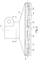
- the loading device 10 has gondolas 17, which in Fig. 2 are shown schematically in a representation from below. It is shown a trough 13 having a bearing surface 16 to which the rod-shaped articles 11, 11 'are applied. There are also shown four suction air openings 14, 14 ', 14 ", 14'", which are each separated from one another by webs 15, 15 ', 15 ".
- the webs 15, 15', 15" are preferably at the same height as the contact surface 16 or aligned with this, so that in the event that when filter segments 11, 11 'are introduced into the trough 13, substantially no suction air is sucked past the webs 15, 15', 15 ", since the filter segments 11, 11 Accordingly, a seal with the contact surface 16 result.
- the suction air openings 14, 14 ', 14 ", 14'” are connected to suction air ducts 20, 20 ', 20 ", 20'", which run separately in the nacelle 17.
- the corresponding separation of these Saugluftkanäle 20-20 '" is in Fig. 3 again shown, in which a schematic section through a corresponding gondola 17 is shown, and approximately along the line AA Fig. 2 , It can be seen that the Saugluftkanäle 20-20 '"through walls are separated from each other.
- Fig. 4 schematically shows a Saugluftdiagramm according to the invention.
- a relatively large suction air supply 30 from which four suction air ducts 32-32 '''branch off, to which suction air ducts 32-32''' join valves 31-31 '', to which the suction air ducts 20-20 '''connect and then a trough 13, which is provided with corresponding Saugluftö réelleen 14-14 '".
- valves 31-31 '" may also be located in the suction air ducts 32-32'" or at the suction air supply 30 before the suction air ducts 32-32 '"begin.
- the Saug poverty horrin 32-32 '" can also be branched off, namely be branched off in the loading device 10 and supply a plurality of gondolas 17 each with suction or supply several Saugluftkanäle 20-20'" with suction.
- the valves 31-31 '" may be arranged in the respective nacelle 17 itself or between the respective nacelle 17 and the Saugluftvorrat 30th
- Saugluftvorrat 30 can be on the valves 31-31 '"completely or at least partially waived.
Abstract
Die Erfindung betrifft eine Einlegevorrichtung (10), die ausgebildet ist, stabförmige Artikel (11, 11') der Tabak verarbeitenden Industrie in einen Strang (12) der Tabak verarbeitenden Industrie einzubringen oder an einen Strang (12) der Tabak verarbeitenden Industrie anzulegen, mit wenigstens einer Mulde (13) zur Aufnahme von stabförmigen Artikeln (11, 11') der Tabak verarbeitenden Industrie, insbesondere von Filtersegmenten, wobei die wenigstens eine Mulde (13) eine Längserstreckung aufweist und wobei die Mulde (13) eine Saugluftöffnung (14, 14', 14", 14'") aufweist, die dadurch fortgebildet ist, dass wenigstens zwei Saugluftöffnungen (14-14'") vorgesehen sind, die mit einem Steg (15, 15', 15") voneinander getrennt sind.The invention relates to an inserting device (10) which is designed to introduce rod-shaped articles (11, 11 ') of the tobacco processing industry into a strand (12) of the tobacco-processing industry or to a strand (12) of the tobacco-processing industry at least one trough (13) for receiving rod-shaped articles (11, 11 ') of the tobacco-processing industry, in particular filter segments, wherein the at least one trough (13) has a longitudinal extent and wherein the trough (13) has a suction air opening (14, 14 ', 14 ", 14' '') formed by providing at least two suction air openings (14-14 '' ') separated by a web (15, 15', 15 '').
Description
Die Erfindung betrifft eine Einlegevorrichtung, die ausgebildet ist, stabförmige Artikel der Tabak verarbeitenden Industrie in einen Strang der Tabak verarbeitenden Industrie einzubringen oder an einen Strang der Tabak verarbeitenden Industrie anzulegen, mit wenigstens einer Mulde zur Aufnahme von stabförmigen Artikeln der Tabak verarbeitenden Industrie, insbesondere von Filtersegmenten, wobei die wenigstens eine Mulde eine Längserstreckung aufweist und wobei die Mulde eine Saugluftöffnung aufweist.The invention relates to an insertion device, which is designed to introduce rod-shaped articles of the tobacco processing industry in a strand of the tobacco processing industry or to create a strand of tobacco processing industry, with at least one trough for receiving rod-shaped articles of the tobacco processing industry, in particular Filter segments, wherein the at least one trough has a longitudinal extent and wherein the trough has a Saugluftöffnung.
Die Erfindung betrifft ferner eine Strangmaschine der Tabak verarbeitenden Industrie mit einer derartigen Einlegevorrichtung.The invention further relates to a rod making machine of the tobacco processing industry with such a loading device.
Bei entsprechenden Einlegevorrichtungen, die auch als Einlegeräder bekannt sind, werden mittels einer Rotationsbewegung stabförmige Artikel der Tabak verarbeitenden Industrie, insbesondere Filtersegmente, von einer queraxialen Förderrichtung in eine längsaxiale Förderrichtung übergeben, um so einen Strang aus diesen stabförmigen Artikeln der Tabak verarbeitenden Industrie bilden zu können.In the case of corresponding insertion devices, which are also known as insertion wheels, rod-shaped articles of the tobacco-processing industry, in particular filter segments, are transferred from a transverse-axial conveying direction into a longitudinal-axial conveying direction by means of a rotational movement, in order to form a strand of these rod-shaped articles of tobacco to be able to form a manufacturing industry.
Eine derartige Vorrichtung ist beispielsweise aus
Es ist nun festgestellt worden, dass es bei einem fehlenden stabförmigen Artikel bei der Übergabe zu unkontrollierten Übergaben kommen kann.It has now been found that in the case of a missing rod-shaped article at the handover, uncontrolled handovers may occur.
Es ist daher Aufgabe der vorliegenden Erfindung, eine bekannte Einlegevorrichtung und eine bekannte Strangmaschine derart weiterzubilden, dass eine sehr hohe Prozesssicherheit bzw. eine sehr genaue Übergabe von stabförmigen Artikeln von einer queraxialen Förderrichtung in einen längsaxial geförderten Strang bzw. an einen längsaxial geförderten Strang ermöglicht ist.It is therefore an object of the present invention to develop a known insertion device and a known stranding machine such that a very high process reliability or a very accurate transfer of rod-shaped articles from a transverse axial conveying direction is made possible in a longitudinally promoted strand or on a längsaxial promoted strand ,
Gelöst wird diese Aufgabe durch eine Einlegevorrichtung, die ausgebildet ist, stabförmige Artikel der Tabak verarbeitenden Industrie in einen Strang der Tabak verarbeitenden Industrie einzubringen oder an einen Strang der Tabak verarbeitenden Industrie anzulegen, mit wenigstens einer Mulde zur Aufnahme von stabförmigen Artikeln der Tabak verarbeitenden Industrie, insbesondere von Filtersegmenten, wobei die wenigstens eine Mulde eine Längserstreckung aufweist und wobei die Mulde eine Saugluftöffnung aufweist, die dadurch weitergebildet ist, dass wenigstens zwei Saugluftöffnungen in der Mulde vorgesehen sind, die durch einen Steg voneinander getrennt sind.This object is achieved by a loading device, which is designed to bring rod-shaped articles of the tobacco processing industry in a strand of tobacco processing industry or put on a strand of the tobacco processing industry, with at least one trough for receiving rod-shaped articles of the tobacco processing industry, in particular filter segments, wherein the at least one trough has a longitudinal extent and wherein the trough has a Saugluftöffnung, which is further developed in that at least two Saugluftöffnungen are provided in the trough, which are separated by a web.
Durch die erfindungsgemäße Einlegevorrichtung wird das Risiko minimiert, dass bei einem fehlenden stabförmigen Artikel, beispielsweise Filtersegment, in einer Mulde der Einlegevorrichtung die Saugluft derart zusammenbricht, dass weitere in der Mulde angeordnete bzw. aufgenommene stabförmige Artikel nicht mehr gehalten werden können bzw. nicht mehr präzise gehalten werden können, so dass diese möglicherweise an falschen Stellen in den Strang eingelegt oder an den Strang angelegt werden. Hierdurch kann es insbesondere zu einem Strangbruch und einem Maschinenstopp kommen. Um den Einfluss eines fehlenden stabförmigen Artikels, beispielsweise eines fehlenden Filtersegments, für den Prozess zu reduzieren, werden wenigstens zwei mit einem Steg voneinander getrennte Saugluftöffnungen vorgesehen.The insertion device according to the invention minimizes the risk that in a missing rod-shaped article, such as filter segment, in a trough of the loading device, the suction air collapses such that further arranged in the trough or recorded rod-shaped article can no longer be held or can not be kept precisely, so this may in the strand or put on the strand. This can in particular lead to a strand break and a machine stop. In order to reduce the influence of a missing rod-shaped article, for example a missing filter segment, for the process, at least two suction air openings separated from each other by a web are provided.
Hierbei sind die Saugluftöffnungen vorzugsweise vollständig voneinander durch den jeweiligen Steg getrennt bzw. sind die Saugluftöffnungen nicht miteinander verbunden.In this case, the suction air openings are preferably completely separated from one another by the respective web or the suction air openings are not connected to one another.
Vorzugsweise weist die Mulde eine Auflagefläche auf, in der ein in die Mulde eingebrachter stabförmiger Artikel anliegt, wobei der Steg, insbesondere längsaxial, mit der Anlagefläche fluchtet, derart, dass ein in die Mulde eingebrachter stabförmiger Artikel an dem Steg anliegt.Preferably, the trough has a bearing surface, in which a rod-shaped article inserted into the trough rests, the web, in particular longitudinally aligned with the contact surface, in such a way that a rod-shaped article inserted into the trough bears against the web.
Vorzugsweise ist der Steg oder sind die Stege an die Kontur der Mulde angepasst, insbesondere von deren Tiefe her mit der restlichen Kontur der Mulde, insbesondere längsaxial, fluchtend ausgelegt. Bei Vorsehen einer im Querschnitt kreisabschnittsförmigen Mulde ist beispielsweise der Steg auch kreisabschnittsförmig im Querschnitt. Es können auch andere Formen vorgesehen sein. Vorzugsweise wird eine Form zu wählen sein, die an die Form der stabförmigen Artikel angepasst ist, wobei insbesondere eine komplementäre Form der Mulde bzw. der Stege zu den stabförmigen Artikeln, die transportiert werden sollen bzw. übergeben werden sollen, vorgesehen ist.Preferably, the web or webs are adapted to the contour of the trough, in particular of its depth with the rest of the contour of the trough, in particular longitudinal axial, aligned. When providing a circular cross-section in the form of a trough, for example, the web is also circular section in cross section. Other shapes may be provided. Preferably, a shape is to be selected which is adapted to the shape of the rod-shaped articles, wherein in particular a complementary shape of the trough or of the webs to the rod-shaped articles to be transported or be handed over, is provided.
Vorzugsweise ist die wenigstens eine Mulde auf einer Gondel angeordnet, wobei bei einer Rotation der Einlegevorrichtung um eine Rotationsachse eine Bewegung, insbesondere Verschwenkung, der Gondel vorgesehen ist, die für eine parallele Ausrichtung der wenigstens einen Mulde sorgt.Preferably, the at least one trough is arranged on a nacelle, wherein upon rotation of the loading device about an axis of rotation a movement, in particular pivoting, the nacelle is provided, which ensures a parallel alignment of the at least one trough.
Im Rahmen der Erfindung kann für das Wort Gondel auch Träger verwendet werden.In the context of the invention, carriers can also be used for the word gondola.
Die Rotationsachse der Gondel ist vorzugsweise parallel zu der Rotationsachse der Einlegevorrichtung.The axis of rotation of the nacelle is preferably parallel to the axis of rotation of the loading device.
Vorzugsweise weist die Einlegevorrichtung mehrere Gondeln auf. Die Gondeln können mit einer Mulde versehen sein, um beispielsweise stabförmige Artikel in einen Strang abzugeben. Es können allerdings auch zwei oder mehr nebeneinander, vorzugsweise parallel nebeneinander, angeordnete Mulden je Gondel vorgesehen sein, um zwei oder mehr Stränge mit stabförmigen Artikeln der Tabak verarbeitenden Industrie, insbesondere gleichzeitig, zu versorgen.Preferably, the loading device has a plurality of gondolas. The gondolas may be provided with a trough, for example, to deliver rod-shaped articles in a strand. However, two or more side by side, preferably parallel to each other, arranged troughs per gondola may be provided to supply two or more strands with rod-shaped articles of the tobacco-processing industry, in particular at the same time.
Vorzugsweise ist für jede Saugluftöffnung ein Saugluftkanal vorgesehen. Vorzugsweise ist jede Saugluftöffnung einer Gondel einzeln schaltbar. Zum Schalten kann beispielsweise ein Ventil vorgesehen sein bzw. kann für jede Saugluftöffnung einzeln ein Ventil vorgesehen sein. Durch das Schalten ist die Saugluft zu- bzw. abschaltbar. Hierdurch ist eine sehr hohe Prozesssicherheit ermöglicht.Preferably, a suction air duct is provided for each suction air opening. Preferably, each suction air opening of a nacelle is individually switchable. For switching, for example, a valve may be provided or may be provided individually for each Saugluftöffnung a valve. By switching the suction air is switched on or off. This allows a very high process reliability.
Wenn ein entsprechend großer Saugluftvorrat vorgesehen ist, kann allerdings auch unter Umständen auf das einzelne Schalten der Saugluftöffnungen verzichtet werden, da bei einem entsprechend großen Saugluftvorrat bzw. Saugluftreservoir ein Verlust von Saugluft über einen getrennten Saugluftkanal und eine getrennte Saugluftleitung zu dem Saugluftvorrat hin keinen ins Gewicht fallenden Verlust an Saugluft im Saugluftvorrat erzeugt.If a correspondingly large intake air supply is provided, however, the individual switching of the suction air openings may also be dispensed with, since with a correspondingly large suction air reservoir or suction air reservoir, a loss of suction air via a separate suction air duct and a separate suction air line to the suction air supply is of no importance falling loss of suction in Saugluftvorrat generated.
Das oder die Ventile können vorzugsweise in jeder Gondel angeordnet sein oder in einer Saugluftleitung oder mehreren Saugluftleitungen in einer Einlegevorrichtung angeordnet sein. Die Ventile können auch einer Einlegevorrichtung vorgeschaltet bzw. entfernt von der Einlegevorrichtung angeordnet sein. Es kann auch vorgesehen sein, dass ein Ventil eine erste Saugluftöffnung in einer ersten Gondel und einer zweiten Gondel zu- und abschalten kann und entsprechend ein zweites Ventil eine zweite Saugluftöffnung einer ersten Gondel und eine zweite Saugluftöffnung einer zweiten Gondel zu- und abschalten kann und entsprechend für weitere Saugluftöffnungen einer oder mehrerer Gondeln ein oder mehrere Ventile vorgesehen sind. Dieses wird im Zusammenhang mit den Figuren noch näher erläutert.The one or more valves may preferably be arranged in each nacelle or in a suction air duct or several suction air ducts in one Be arranged loading device. The valves can also be arranged upstream of an insertion device or remote from the insertion device. It can also be provided that a valve can switch on and off a first suction air opening in a first nacelle and a second nacelle, and a second valve can connect and disconnect a second suction air opening of a first nacelle and a second suction air opening of a second nacelle and accordingly one or more valves are provided for further suction air openings of one or more gondolas. This will be explained in more detail in connection with the figures.
Vorzugsweise ist für jeden stabförmigen Artikel eine Saugluftöffnung vorgesehen, wobei hierbei insbesondere der stabförmige Artikel in die Mulde einbringbar ist oder eingebracht wird.Preferably, a Saugluftöffnung is provided for each rod-shaped article, in which case in particular the rod-shaped article is introduced into the trough or is introduced.
Die Aufgabe wird ferner durch eine Strangmaschine der Tabak verarbeitenden Industrie mit einer erfindungsgemäßen Einlegevorrichtung gelöst, wobei mittels der Einlegevorrichtung stabförmige Artikel auf eine Formatvorrichtung oder eine Fördervorrichtung auflegbar sind oder aufgelegt werden, so dass sich ein Strang aus stabförmigen Artikeln bildet.The object is further achieved by an extrusion machine of the tobacco-processing industry with an insertion device according to the invention, wherein by means of the insertion device rod-shaped articles are placed on a formatting device or a conveying device or are placed so that forms a strand of rod-shaped articles.
Vorzugsweise ist die wenigstens eine Mulde parallel zu dem Strang oder der Formatvorrichtung angeordnet.Preferably, the at least one trough is arranged parallel to the strand or the format device.
Vorzugsweise ist ein Saugluftvorrat vorgesehen, von dem die Saugluftkanäle mit Saugluft gespeist werden oder mit Saugluft speisbar sind.Preferably, a Saugluftvorrat is provided, from which the Saugluftkanäle are fed with suction or can be fed with suction air.
Vorzugsweise ist jedem Saugluftkanal einer Gondel ein Ventil zugeordnet. Vorzugsweise kann ein Ventil für jeweils eine Saugluftleitung mehrerer Gondeln vorgesehen sein.Preferably, each intake air duct of a nacelle is assigned a valve. Preferably, a valve may be provided for each suction air duct of a plurality of gondolas.
Bei der Übergabe von stabförmigen Artikeln, insbesondere Filtersegmenten, aus einer Rotationsbewegung in eine längsaxiale Förderrichtung mithilfe eines Trägers oder einer Gondel, die eine Mulde aufweist, besteht das Risiko, dass bei einem oder mehreren fehlenden stabförmigen Artikeln bzw. Segmenten auf der Mulde die Halteluft zusammenbricht. Wenn sich der Unterdruck bzw. die Saugluft zum Halten der stabförmigen Artikel auf der Mulde zu stark reduziert, entsteht ein großes Prozessrisiko, da die weiteren stabförmigen Artikel bzw. Segmente nicht mehr auf oder in der Mulde gehalten werden können. Für diesen Fall können eine oder mehrere weitere Segmente aus der Mulde fallen und es zu einem Strangbruch und damit einem Maschinenstopp kommen.In the transfer of rod-shaped articles, in particular filter segments, from a rotational movement in a longitudinal axial conveying direction by means of a carrier or a nacelle having a trough exists the risk that one or more missing rod-shaped articles or segments on the trough collapses the holding air. If the negative pressure or the suction air for holding the rod-shaped articles on the trough is reduced too much, a great process risk arises because the further rod-shaped articles or segments can no longer be held on or in the trough. In this case, one or more further segments may fall out of the trough and cause a strand break and thus a machine stop.
Erfindungsgemäß werden in die Mulde zwei oder mehrere separate Saugkanäle oder Saugluftöffnungen eingebracht.According to the invention, two or more separate suction channels or suction air openings are introduced into the trough.
Durch die Kanäle wird verhindert, dass der Unterdruck bzw. die Saugluft komplett in der Mulde bzw. der Gondel zusammenbricht und verbleibende Segmente bzw. stabförmige Artikel werden somit prozesssicher gehalten. Die Saugluftöffnungen oder die Saugluftkanäle können gleichmäßig bzw. gleich groß verteilt oder ausgebildet sein oder von deren Größe her auf die einzelnen aufzunehmenden bzw. zu fördernden stabförmigen Artikel angepasst werden. Einem größeren stabförmigen Artikel kann beispielsweise eine größere Saugluftöffnung zugeordnet werden als einem kleineren stabförmigen Artikel. Entsprechend können schwerere stabförmige Artikel eine größere Saugluftöffnung erhalten, als leichtere stabförmige Artikel.Through the channels prevents the negative pressure or the suction air completely collapses in the trough or the nacelle and thus remaining segments or rod-shaped articles are kept safe. The suction air openings or the suction air ducts can be distributed or formed uniformly or evenly or can be adapted in size to the individual male or to be conveyed rod-shaped article. For example, a larger rod-shaped article may be assigned a larger suction air opening than a smaller rod-shaped article. Accordingly, heavier rod-shaped articles can receive a larger suction air opening than lighter rod-shaped articles.
Ein zusätzlicher überraschender Effekt dieser Art der Muldenausbildung einer entsprechenden Einlegevorrichtung ist der, dass sich eine vergrößerte Reibfläche zwischen den stabförmigen Artikeln und der Mulde ergibt, was den Einlegeprozess in einem Strang oder an einen Strang verbessert. Durch die Stege in der Mulde wird eine zusätzliche höhere Stabilität erzielt. Vorzugsweise wird auch noch eine Kante, die in längsaxialer Richtung der Mulde die Mulde abschließt, versteift, um eine genaue Platzierung der stabförmigen Artikel in den Strang oder an den Strang zu ermöglichen.An additional surprising effect of this type of trough formation of a corresponding loading device is that it results in an increased friction surface between the rod-shaped articles and the trough, which improves the insertion process in a strand or strand. By the webs in the trough an additional higher stability is achieved. Preferably, also an edge, which closes the trough in the longitudinal axial direction of the trough, stiffened to allow accurate placement of the rod-shaped article in the strand or on the strand.
Weitere Merkmale der Erfindung werden aus der Beschreibung erfindungsgemäßer Ausführungsformen zusammen mit den Ansprüchen und den beigefügten Zeichnungen ersichtlich. Erfindungsgemäße Ausführungsformen können einzelne Merkmale oder eine Kombination mehrerer Merkmale erfüllen.Further features of the invention will become apparent from the description of embodiments according to the invention together with the claims and the accompanying drawings. Embodiments of the invention may satisfy individual features or a combination of several features.
Die Erfindung wird nachstehend ohne Beschränkung des allgemeinen Erfindungsgedankens anhand von Ausführungsbeispielen unter Bezugnahme auf die Zeichnungen beschrieben, wobei bezüglich aller im Text nicht näher erläuterten erfindungsgemäßen Einzelheiten ausdrücklich auf die Zeichnungen verwiesen wird. Es zeigen:
- Fig. 1
- eine schematische Ansicht einer üblichen Strangmaschine der Tabak verarbeitenden Industrie,
- Fig. 2
- eine schematische Ansicht einer Gondel einer erfindungsgemäßen Einlegevorrichtung von unten,
- Fig. 3
- eine schematische Ansicht eines Schnitts durch eine Gondel einer erfindungsgemäßen Einlegevorrichtung und
- Fig. 4
- eine schematische Darstellung einer erfindungsgemäßen Saugluftverteilung.
- Fig. 1
- a schematic view of a conventional extrusion machine of the tobacco processing industry,
- Fig. 2
- a schematic view of a nacelle of a loading device according to the invention from below,
- Fig. 3
- a schematic view of a section through a nacelle of a loading device according to the invention and
- Fig. 4
- a schematic representation of a Saugluftverteilung invention.
In den Zeichnungen sind jeweils gleiche oder gleichartige Elemente und/oder Teile mit denselben Bezugsziffern versehen, so dass von einer erneuten Vorstellung jeweils abgesehen wird.In the drawings, the same or similar elements and / or parts are provided with the same reference numerals, so that apart from a new idea each.
Die aufgenommenen Filtersegmente 11, 11' werden längsaxial in einen Strang 12 übergeben. Hierzu werden die Filtersegmente 11, 11' auf einen Umhüllungsmaterialstreifen 35, der auf einem Formatband 34 aufgebracht ist, aufgelegt. Das Formatband 34 bewegt sich in Pfeilrichtung, d.h. in
Die erfindungsgemäße Einlegevorrichtung 10 weist Gondeln 17 auf, die in
Die Saugluftöffnungen 14, 14', 14", 14'" sind mit Saugluftkanälen 20, 20', 20", 20'" verbunden, die jeweils getrennt in der Gondel 17 verlaufen. Die entsprechende Trennung dieser Saugluftkanäle 20-20'" ist in
Die Ventile 31-31'" können auch in den Saugluftleitungen 32-32'" angeordnet sein oder an dem Saugluftvorrat 30, bevor die Saugluftleitungen 32-32'" beginnen.The valves 31-31 '"may also be located in the suction air ducts 32-32'" or at the
Die Saugluftleitungen 32-32'" können auch abgezweigt sein, und zwar in der Einlegevorrichtung 10 abgezweigt sein und mehrere Gondeln 17 jeweils mit Saugluft versorgen bzw. mehrere Saugluftkanäle 20-20'" mit Saugluft versorgen. Die Ventile 31-31'" können in der jeweiligen Gondel 17 selbst angeordnet sein oder zwischen der jeweiligen Gondel 17 und dem Saugluftvorrat 30.The Saugluftleitungen 32-32 '"can also be branched off, namely be branched off in the
Bei einem ausreichend großen Saugluftvorrat 30 kann auf die Ventile 31-31'" auch vollständig oder wenigstens zum Teil verzichtet werden.With a sufficiently
Alle genannten Merkmale, auch die den Zeichnungen allein zu entnehmenden sowie auch einzelne Merkmale, die in Kombination mit anderen Merkmalen offenbart sind, werden allein und in Kombination als erfindungswesentlich angesehen. Erfindungsgemäße Ausführungsformen können durch einzelne Merkmale oder eine Kombination mehrerer Merkmale erfüllt sein. Im Rahmen der Erfindung sind Merkmale, die mit "insbesondere" oder "vorzugsweise" gekennzeichnet sind, als fakultative Merkmale zu verstehen.All mentioned features, including the drawings alone to be taken as well as individual features that are disclosed in combination with other features are considered alone and in combination as essential to the invention. Embodiments of the invention may be accomplished by individual features or a combination of several features. In the context of the invention, features which are identified by "particular" or "preferably" are to be understood as optional features.
- 1010
- Einlegevorrichtungloading device
- 11, 11'11, 11 '
- Filtersegmentfilter segment
- 1212
- Filterstrangfilter rod
- 1313
- Muldetrough
- 14, 14', 14", 14'"14, 14 ', 14 ", 14'"
- Saugluftöffnungsuction air
- 15, 15', 15"15, 15 ', 15 "
- Stegweb
- 1616
- Anlageflächecontact surface
- 1717
- Gondelgondola
- 1818
- Rotationsachseaxis of rotation
- 1919
- Rotationsachseaxis of rotation
- 20, 20', 20", 20'"20, 20 ', 20 ", 20'"
- Saugluftkanalsuction air channel
- 2121
- Strangmaschinerod machine
- 2222
- Formatvorrichtungformat device
- 3030
- SaugluftvorratSaugluftvorrat
- 31, 31', 31", 31'"31, 31 ', 31 ", 31'"
- VentilValve
- 32, 32', 32", 32'"32, 32 ', 32 ", 32'"
- Saugluftleitungsuction air
- 3333
- Schneidvorrichtungcutter
- 3434
- Formatbandformat tape
- 3535
- UmhüllungsmaterialstreifenWrapping material strip
Claims (10)
Priority Applications (1)
| Application Number | Priority Date | Filing Date | Title |
|---|---|---|---|
| PL17170795T PL3248477T3 (en) | 2016-05-26 | 2017-05-12 | Insertion device and rod making machine for the tobacco processing industry |
Applications Claiming Priority (1)
| Application Number | Priority Date | Filing Date | Title |
|---|---|---|---|
| DE102016109740.3A DE102016109740A1 (en) | 2016-05-26 | 2016-05-26 | Insertion device and strand machine of the tobacco processing industry |
Publications (2)
| Publication Number | Publication Date |
|---|---|
| EP3248477A1 true EP3248477A1 (en) | 2017-11-29 |
| EP3248477B1 EP3248477B1 (en) | 2020-10-21 |
Family
ID=58707382
Family Applications (1)
| Application Number | Title | Priority Date | Filing Date |
|---|---|---|---|
| EP17170795.3A Active EP3248477B1 (en) | 2016-05-26 | 2017-05-12 | Insertion device and rod making machine for the tobacco processing industry |
Country Status (4)
| Country | Link |
|---|---|
| EP (1) | EP3248477B1 (en) |
| CN (1) | CN107432492B (en) |
| DE (1) | DE102016109740A1 (en) |
| PL (1) | PL3248477T3 (en) |
Families Citing this family (3)
| Publication number | Priority date | Publication date | Assignee | Title |
|---|---|---|---|---|
| DE102016111818B4 (en) | 2016-06-28 | 2018-10-11 | Hauni Maschinenbau Gmbh | Positioning rod-shaped articles of the tobacco processing industry in a loading device |
| PL3669672T3 (en) * | 2018-12-19 | 2022-04-19 | International Tobacco Machinery Poland Sp. Z O.O. | A method and an apparatus for manufacturing rod-like articles for tobacco industry |
| DE102021116593A1 (en) | 2021-06-28 | 2022-12-29 | Körber Technologies Gmbh | Groups of filter segments with gaps |
Citations (4)
| Publication number | Priority date | Publication date | Assignee | Title |
|---|---|---|---|---|
| DE2534666A1 (en) * | 1974-10-15 | 1976-04-29 | Hauni Werke Koerber & Co Kg | DEVICE FOR MANUFACTURING COMBINED FILTER PLUGS FOR FILTER CIGARETTES OR OTHER ROD-SHAPED OBJECTS IN THE TOBACCO-PROCESSING INDUSTRY |
| DE2547920A1 (en) * | 1975-10-25 | 1977-04-28 | Hauni Werke Koerber & Co Kg | Handling system for e.g. cigarette filter plugs - has plugs and glued casing fed along curved tracks before transfer of plugs to casing |
| DE2809160A1 (en) | 1978-03-03 | 1979-09-06 | Hauni Werke Koerber & Co Kg | Combination cigarette filter transfer device - with distance lug on leading end of holder for accurate cavity recess |
| EP2641486A1 (en) * | 2012-03-22 | 2013-09-25 | G.D S.p.A. | Device for transferring pieces of filter or cigarette rod |
Family Cites Families (10)
| Publication number | Priority date | Publication date | Assignee | Title |
|---|---|---|---|---|
| US3303926A (en) | 1965-07-08 | 1967-02-14 | American Mach & Foundry | Cigarette collector |
| DE1632213A1 (en) * | 1967-11-09 | 1970-08-06 | Hauni Werke Koerber & Co Kg | Conveyor device with at least one receptacle for a cigarette rod or for cigarettes |
| IT1133485B (en) | 1980-08-29 | 1986-07-09 | Cir Spa Divisione Sasib | DEVICE FOR THE AUTOMATIC ADJUSTMENT OF THE SUCTION IN THE CELLS OF A PNEUMATIC TRANSFER DRUM |
| IT1147391B (en) | 1981-07-28 | 1986-11-19 | Sasib Spa | TRANSFER DEVICE FOR ASTIFORM OBJECTS IN PARTICULAR OF CIGARETTES |
| IT1293300B1 (en) | 1997-08-06 | 1999-02-16 | Gd Spa | CIGARETTE CUTTING TRANSFER DEVICE. |
| ITBO20040495A1 (en) * | 2004-08-03 | 2004-11-03 | Gd Spa | DU TRANSFER EQUIPMENT FOR BAR ITEMS |
| ITBO20060718A1 (en) | 2006-10-18 | 2008-04-19 | Gd Spa | MACHINE FOR THE PRODUCTION OF COMPOUND FILTERS |
| DE102009022024B4 (en) * | 2009-05-15 | 2011-06-16 | Hauni Maschinenbau Ag | Conveying device with vacuum suction |
| DE102009041318A1 (en) * | 2009-09-15 | 2011-03-31 | Hauni Maschinenbau Ag | Inserting filter segments in filter strands |
| ITBO20110158A1 (en) | 2011-03-28 | 2012-09-29 | Gd Spa | TRANSFER OR ACCOMPANIMENT DRUM FOR FILTER OR CIGARETTE CUTTERS WITH OPERATIONAL HEADS CARRIED BY RADIAL ARMS. |
-
2016
- 2016-05-26 DE DE102016109740.3A patent/DE102016109740A1/en active Pending
-
2017
- 2017-05-12 EP EP17170795.3A patent/EP3248477B1/en active Active
- 2017-05-12 PL PL17170795T patent/PL3248477T3/en unknown
- 2017-05-26 CN CN201710385855.4A patent/CN107432492B/en active Active
Patent Citations (4)
| Publication number | Priority date | Publication date | Assignee | Title |
|---|---|---|---|---|
| DE2534666A1 (en) * | 1974-10-15 | 1976-04-29 | Hauni Werke Koerber & Co Kg | DEVICE FOR MANUFACTURING COMBINED FILTER PLUGS FOR FILTER CIGARETTES OR OTHER ROD-SHAPED OBJECTS IN THE TOBACCO-PROCESSING INDUSTRY |
| DE2547920A1 (en) * | 1975-10-25 | 1977-04-28 | Hauni Werke Koerber & Co Kg | Handling system for e.g. cigarette filter plugs - has plugs and glued casing fed along curved tracks before transfer of plugs to casing |
| DE2809160A1 (en) | 1978-03-03 | 1979-09-06 | Hauni Werke Koerber & Co Kg | Combination cigarette filter transfer device - with distance lug on leading end of holder for accurate cavity recess |
| EP2641486A1 (en) * | 2012-03-22 | 2013-09-25 | G.D S.p.A. | Device for transferring pieces of filter or cigarette rod |
Also Published As
| Publication number | Publication date |
|---|---|
| PL3248477T3 (en) | 2021-05-31 |
| CN107432492A (en) | 2017-12-05 |
| EP3248477B1 (en) | 2020-10-21 |
| CN107432492B (en) | 2021-07-30 |
| DE102016109740A1 (en) | 2017-11-30 |
Similar Documents
| Publication | Publication Date | Title |
|---|---|---|
| EP2696708B9 (en) | Conveying rod-like articles in the tobacco-processing industry | |
| DE1243071B (en) | Method and device for the transverse axial production of filter rods for filter cigarettes or other rod-shaped objects | |
| EP1625799A1 (en) | Arrangement for the manufacture of at least one filter rod | |
| EP3248477B1 (en) | Insertion device and rod making machine for the tobacco processing industry | |
| DE102010002132A1 (en) | Tobacco strand machine for the production of tobacco rods, filter attachment machine for connecting filters with tobacco rods and cigarette making machine | |
| EP1374706B1 (en) | Filter feeding for a filter assembly machine | |
| DE102015110516A1 (en) | Composing segments of the tobacco processing industry | |
| DE2162295B2 (en) | Method and apparatus for making mouthpiece cigarettes | |
| EP1441604A1 (en) | Device for wrapping groups of filter segments with a wrapping material for producing multi-segment filers of the tobacco industry and multi-segment filter production device | |
| EP3281537A2 (en) | Transport drum for the tobacco processing industry | |
| EP2449896B1 (en) | Device for producing coaxial filters for smokeable rod shaped articles | |
| EP2353408A2 (en) | Transport drum for the tobacco processing industry | |
| EP3434117B1 (en) | Preparation of rod-like smoking products | |
| DE102009016311A1 (en) | Conveyor drum of the tobacco processing industry | |
| DE102005051525B4 (en) | Filterzuführeinrichtung | |
| EP3262959B1 (en) | Positioning of rod-shaped articles of the tobacco processing industry into an insertion device | |
| EP1527703B1 (en) | Staggered drum | |
| EP1897454B1 (en) | V-shaped assembly of suction apertures | |
| EP2756768B1 (en) | Device for longitudinally conveying rod-shaped products in the tobacco processing industry | |
| DE1188997B (en) | Device for making mouthpiece cigarettes | |
| DE3617252A1 (en) | METHOD AND DEVICE FOR PRODUCING A STRING OF FIBERS OF THE TOBACCO-PROCESSING INDUSTRY | |
| WO2011000467A1 (en) | Duct wall of a rod-conveying device of a machine of the tobacco processing industry | |
| DE102012213338B4 (en) | Method and device for producing multi-segment filter rods of the tobacco processing industry | |
| EP2729025A1 (en) | Longitudinal conveying arrangement for products in the tobacco-processing industry | |
| EP3189740B1 (en) | Method for producing a multisegment filter and multisegment filter production apparatus for the tobacco industry |
Legal Events
| Date | Code | Title | Description |
|---|---|---|---|
| PUAI | Public reference made under article 153(3) epc to a published international application that has entered the european phase |
Free format text: ORIGINAL CODE: 0009012 |
|
| STAA | Information on the status of an ep patent application or granted ep patent |
Free format text: STATUS: THE APPLICATION HAS BEEN PUBLISHED |
|
| AK | Designated contracting states |
Kind code of ref document: A1 Designated state(s): AL AT BE BG CH CY CZ DE DK EE ES FI FR GB GR HR HU IE IS IT LI LT LU LV MC MK MT NL NO PL PT RO RS SE SI SK SM TR |
|
| AX | Request for extension of the european patent |
Extension state: BA ME |
|
| STAA | Information on the status of an ep patent application or granted ep patent |
Free format text: STATUS: REQUEST FOR EXAMINATION WAS MADE |
|
| 17P | Request for examination filed |
Effective date: 20180430 |
|
| RBV | Designated contracting states (corrected) |
Designated state(s): AL AT BE BG CH CY CZ DE DK EE ES FI FR GB GR HR HU IE IS IT LI LT LU LV MC MK MT NL NO PL PT RO RS SE SI SK SM TR |
|
| GRAP | Despatch of communication of intention to grant a patent |
Free format text: ORIGINAL CODE: EPIDOSNIGR1 |
|
| STAA | Information on the status of an ep patent application or granted ep patent |
Free format text: STATUS: GRANT OF PATENT IS INTENDED |
|
| INTG | Intention to grant announced |
Effective date: 20200615 |
|
| GRAS | Grant fee paid |
Free format text: ORIGINAL CODE: EPIDOSNIGR3 |
|
| GRAA | (expected) grant |
Free format text: ORIGINAL CODE: 0009210 |
|
| STAA | Information on the status of an ep patent application or granted ep patent |
Free format text: STATUS: THE PATENT HAS BEEN GRANTED |
|
| AK | Designated contracting states |
Kind code of ref document: B1 Designated state(s): AL AT BE BG CH CY CZ DE DK EE ES FI FR GB GR HR HU IE IS IT LI LT LU LV MC MK MT NL NO PL PT RO RS SE SI SK SM TR |
|
| REG | Reference to a national code |
Ref country code: GB Ref legal event code: FG4D Free format text: NOT ENGLISH |
|
| REG | Reference to a national code |
Ref country code: CH Ref legal event code: EP |
|
| REG | Reference to a national code |
Ref country code: IE Ref legal event code: FG4D Free format text: LANGUAGE OF EP DOCUMENT: GERMAN |
|
| REG | Reference to a national code |
Ref country code: DE Ref legal event code: R096 Ref document number: 502017007807 Country of ref document: DE |
|
| REG | Reference to a national code |
Ref country code: AT Ref legal event code: REF Ref document number: 1324904 Country of ref document: AT Kind code of ref document: T Effective date: 20201115 |
|
| REG | Reference to a national code |
Ref country code: NL Ref legal event code: FP |
|
| PG25 | Lapsed in a contracting state [announced via postgrant information from national office to epo] |
Ref country code: GR Free format text: LAPSE BECAUSE OF FAILURE TO SUBMIT A TRANSLATION OF THE DESCRIPTION OR TO PAY THE FEE WITHIN THE PRESCRIBED TIME-LIMIT Effective date: 20210122 Ref country code: FI Free format text: LAPSE BECAUSE OF FAILURE TO SUBMIT A TRANSLATION OF THE DESCRIPTION OR TO PAY THE FEE WITHIN THE PRESCRIBED TIME-LIMIT Effective date: 20201021 Ref country code: RS Free format text: LAPSE BECAUSE OF FAILURE TO SUBMIT A TRANSLATION OF THE DESCRIPTION OR TO PAY THE FEE WITHIN THE PRESCRIBED TIME-LIMIT Effective date: 20201021 Ref country code: PT Free format text: LAPSE BECAUSE OF FAILURE TO SUBMIT A TRANSLATION OF THE DESCRIPTION OR TO PAY THE FEE WITHIN THE PRESCRIBED TIME-LIMIT Effective date: 20210222 Ref country code: NO Free format text: LAPSE BECAUSE OF FAILURE TO SUBMIT A TRANSLATION OF THE DESCRIPTION OR TO PAY THE FEE WITHIN THE PRESCRIBED TIME-LIMIT Effective date: 20210121 |
|
| REG | Reference to a national code |
Ref country code: LT Ref legal event code: MG4D |
|
| PG25 | Lapsed in a contracting state [announced via postgrant information from national office to epo] |
Ref country code: ES Free format text: LAPSE BECAUSE OF FAILURE TO SUBMIT A TRANSLATION OF THE DESCRIPTION OR TO PAY THE FEE WITHIN THE PRESCRIBED TIME-LIMIT Effective date: 20201021 Ref country code: BG Free format text: LAPSE BECAUSE OF FAILURE TO SUBMIT A TRANSLATION OF THE DESCRIPTION OR TO PAY THE FEE WITHIN THE PRESCRIBED TIME-LIMIT Effective date: 20210121 Ref country code: LV Free format text: LAPSE BECAUSE OF FAILURE TO SUBMIT A TRANSLATION OF THE DESCRIPTION OR TO PAY THE FEE WITHIN THE PRESCRIBED TIME-LIMIT Effective date: 20201021 Ref country code: IS Free format text: LAPSE BECAUSE OF FAILURE TO SUBMIT A TRANSLATION OF THE DESCRIPTION OR TO PAY THE FEE WITHIN THE PRESCRIBED TIME-LIMIT Effective date: 20210221 Ref country code: SE Free format text: LAPSE BECAUSE OF FAILURE TO SUBMIT A TRANSLATION OF THE DESCRIPTION OR TO PAY THE FEE WITHIN THE PRESCRIBED TIME-LIMIT Effective date: 20201021 |
|
| PG25 | Lapsed in a contracting state [announced via postgrant information from national office to epo] |
Ref country code: HR Free format text: LAPSE BECAUSE OF FAILURE TO SUBMIT A TRANSLATION OF THE DESCRIPTION OR TO PAY THE FEE WITHIN THE PRESCRIBED TIME-LIMIT Effective date: 20201021 |
|
| REG | Reference to a national code |
Ref country code: DE Ref legal event code: R026 Ref document number: 502017007807 Country of ref document: DE |
|
| PLBI | Opposition filed |
Free format text: ORIGINAL CODE: 0009260 |
|
| PG25 | Lapsed in a contracting state [announced via postgrant information from national office to epo] |
Ref country code: EE Free format text: LAPSE BECAUSE OF FAILURE TO SUBMIT A TRANSLATION OF THE DESCRIPTION OR TO PAY THE FEE WITHIN THE PRESCRIBED TIME-LIMIT Effective date: 20201021 Ref country code: CZ Free format text: LAPSE BECAUSE OF FAILURE TO SUBMIT A TRANSLATION OF THE DESCRIPTION OR TO PAY THE FEE WITHIN THE PRESCRIBED TIME-LIMIT Effective date: 20201021 Ref country code: LT Free format text: LAPSE BECAUSE OF FAILURE TO SUBMIT A TRANSLATION OF THE DESCRIPTION OR TO PAY THE FEE WITHIN THE PRESCRIBED TIME-LIMIT Effective date: 20201021 Ref country code: SM Free format text: LAPSE BECAUSE OF FAILURE TO SUBMIT A TRANSLATION OF THE DESCRIPTION OR TO PAY THE FEE WITHIN THE PRESCRIBED TIME-LIMIT Effective date: 20201021 Ref country code: RO Free format text: LAPSE BECAUSE OF FAILURE TO SUBMIT A TRANSLATION OF THE DESCRIPTION OR TO PAY THE FEE WITHIN THE PRESCRIBED TIME-LIMIT Effective date: 20201021 Ref country code: SK Free format text: LAPSE BECAUSE OF FAILURE TO SUBMIT A TRANSLATION OF THE DESCRIPTION OR TO PAY THE FEE WITHIN THE PRESCRIBED TIME-LIMIT Effective date: 20201021 |
|
| PLAX | Notice of opposition and request to file observation + time limit sent |
Free format text: ORIGINAL CODE: EPIDOSNOBS2 |
|
| 26 | Opposition filed |
Opponent name: G.D S.P.A. Effective date: 20210721 |
|
| PG25 | Lapsed in a contracting state [announced via postgrant information from national office to epo] |
Ref country code: DK Free format text: LAPSE BECAUSE OF FAILURE TO SUBMIT A TRANSLATION OF THE DESCRIPTION OR TO PAY THE FEE WITHIN THE PRESCRIBED TIME-LIMIT Effective date: 20201021 |
|
| PG25 | Lapsed in a contracting state [announced via postgrant information from national office to epo] |
Ref country code: AL Free format text: LAPSE BECAUSE OF FAILURE TO SUBMIT A TRANSLATION OF THE DESCRIPTION OR TO PAY THE FEE WITHIN THE PRESCRIBED TIME-LIMIT Effective date: 20201021 |
|
| PG25 | Lapsed in a contracting state [announced via postgrant information from national office to epo] |
Ref country code: SI Free format text: LAPSE BECAUSE OF FAILURE TO SUBMIT A TRANSLATION OF THE DESCRIPTION OR TO PAY THE FEE WITHIN THE PRESCRIBED TIME-LIMIT Effective date: 20201021 |
|
| PLBB | Reply of patent proprietor to notice(s) of opposition received |
Free format text: ORIGINAL CODE: EPIDOSNOBS3 |
|
| REG | Reference to a national code |
Ref country code: CH Ref legal event code: PL |
|
| GBPC | Gb: european patent ceased through non-payment of renewal fee |
Effective date: 20210512 |
|
| PG25 | Lapsed in a contracting state [announced via postgrant information from national office to epo] |
Ref country code: MC Free format text: LAPSE BECAUSE OF FAILURE TO SUBMIT A TRANSLATION OF THE DESCRIPTION OR TO PAY THE FEE WITHIN THE PRESCRIBED TIME-LIMIT Effective date: 20201021 Ref country code: LU Free format text: LAPSE BECAUSE OF NON-PAYMENT OF DUE FEES Effective date: 20210512 Ref country code: LI Free format text: LAPSE BECAUSE OF NON-PAYMENT OF DUE FEES Effective date: 20210531 Ref country code: CH Free format text: LAPSE BECAUSE OF NON-PAYMENT OF DUE FEES Effective date: 20210531 |
|
| REG | Reference to a national code |
Ref country code: BE Ref legal event code: MM Effective date: 20210531 |
|
| PG25 | Lapsed in a contracting state [announced via postgrant information from national office to epo] |
Ref country code: IE Free format text: LAPSE BECAUSE OF NON-PAYMENT OF DUE FEES Effective date: 20210512 Ref country code: GB Free format text: LAPSE BECAUSE OF NON-PAYMENT OF DUE FEES Effective date: 20210512 |
|
| PG25 | Lapsed in a contracting state [announced via postgrant information from national office to epo] |
Ref country code: IS Free format text: LAPSE BECAUSE OF FAILURE TO SUBMIT A TRANSLATION OF THE DESCRIPTION OR TO PAY THE FEE WITHIN THE PRESCRIBED TIME-LIMIT Effective date: 20210221 Ref country code: FR Free format text: LAPSE BECAUSE OF NON-PAYMENT OF DUE FEES Effective date: 20210531 |
|
| PG25 | Lapsed in a contracting state [announced via postgrant information from national office to epo] |
Ref country code: BE Free format text: LAPSE BECAUSE OF NON-PAYMENT OF DUE FEES Effective date: 20210531 |
|
| REG | Reference to a national code |
Ref country code: DE Ref legal event code: R081 Ref document number: 502017007807 Country of ref document: DE Owner name: KOERBER TECHNOLOGIES GMBH, DE Free format text: FORMER OWNER: HAUNI MASCHINENBAU GMBH, 21033 HAMBURG, DE |
|
| REG | Reference to a national code |
Ref country code: NL Ref legal event code: HC Owner name: KOERBER TECHNOLOGIES GMBH; DE Free format text: DETAILS ASSIGNMENT: CHANGE OF OWNER(S), CHANGE OF OWNER(S) NAME; FORMER OWNER NAME: HAUNI MASCHINENBAU GMBH Effective date: 20221025 |
|
| RAP4 | Party data changed (patent owner data changed or rights of a patent transferred) |
Owner name: KOERBER TECHNOLOGIES GMBH |
|
| APAH | Appeal reference modified |
Free format text: ORIGINAL CODE: EPIDOSCREFNO |
|
| APBM | Appeal reference recorded |
Free format text: ORIGINAL CODE: EPIDOSNREFNO |
|
| APBP | Date of receipt of notice of appeal recorded |
Free format text: ORIGINAL CODE: EPIDOSNNOA2O |
|
| APBM | Appeal reference recorded |
Free format text: ORIGINAL CODE: EPIDOSNREFNO |
|
| APBP | Date of receipt of notice of appeal recorded |
Free format text: ORIGINAL CODE: EPIDOSNNOA2O |
|
| APBQ | Date of receipt of statement of grounds of appeal recorded |
Free format text: ORIGINAL CODE: EPIDOSNNOA3O |
|
| APBQ | Date of receipt of statement of grounds of appeal recorded |
Free format text: ORIGINAL CODE: EPIDOSNNOA3O |
|
| PG25 | Lapsed in a contracting state [announced via postgrant information from national office to epo] |
Ref country code: HU Free format text: LAPSE BECAUSE OF FAILURE TO SUBMIT A TRANSLATION OF THE DESCRIPTION OR TO PAY THE FEE WITHIN THE PRESCRIBED TIME-LIMIT; INVALID AB INITIO Effective date: 20170512 |
|
| PG25 | Lapsed in a contracting state [announced via postgrant information from national office to epo] |
Ref country code: CY Free format text: LAPSE BECAUSE OF FAILURE TO SUBMIT A TRANSLATION OF THE DESCRIPTION OR TO PAY THE FEE WITHIN THE PRESCRIBED TIME-LIMIT Effective date: 20201021 |
|
| REG | Reference to a national code |
Ref country code: AT Ref legal event code: MM01 Ref document number: 1324904 Country of ref document: AT Kind code of ref document: T Effective date: 20220512 |
|
| P01 | Opt-out of the competence of the unified patent court (upc) registered |
Effective date: 20230616 |
|
| PG25 | Lapsed in a contracting state [announced via postgrant information from national office to epo] |
Ref country code: AT Free format text: LAPSE BECAUSE OF NON-PAYMENT OF DUE FEES Effective date: 20220512 |
|
| PGFP | Annual fee paid to national office [announced via postgrant information from national office to epo] |
Ref country code: NL Payment date: 20230525 Year of fee payment: 7 Ref country code: IT Payment date: 20230529 Year of fee payment: 7 Ref country code: DE Payment date: 20230525 Year of fee payment: 7 |
|
| PGFP | Annual fee paid to national office [announced via postgrant information from national office to epo] |
Ref country code: PL Payment date: 20230420 Year of fee payment: 7 |