EP3247828B1 - Riemenscheibe zur installation in einem riemenscheibenantrieb einer jacquardmaschine - Google Patents
Riemenscheibe zur installation in einem riemenscheibenantrieb einer jacquardmaschine Download PDFInfo
- Publication number
- EP3247828B1 EP3247828B1 EP16704476.7A EP16704476A EP3247828B1 EP 3247828 B1 EP3247828 B1 EP 3247828B1 EP 16704476 A EP16704476 A EP 16704476A EP 3247828 B1 EP3247828 B1 EP 3247828B1
- Authority
- EP
- European Patent Office
- Prior art keywords
- pulley
- shaft
- flank
- flank bodies
- cavity
- Prior art date
- Legal status (The legal status is an assumption and is not a legal conclusion. Google has not performed a legal analysis and makes no representation as to the accuracy of the status listed.)
- Active
Links
Images

Classifications
-
- D—TEXTILES; PAPER
- D03—WEAVING
- D03C—SHEDDING MECHANISMS; PATTERN CARDS OR CHAINS; PUNCHING OF CARDS; DESIGNING PATTERNS
- D03C3/00—Jacquards
- D03C3/24—Features common to jacquards of different types
-
- D—TEXTILES; PAPER
- D03—WEAVING
- D03C—SHEDDING MECHANISMS; PATTERN CARDS OR CHAINS; PUNCHING OF CARDS; DESIGNING PATTERNS
- D03C3/00—Jacquards
Definitions
- This invention relates to a pulley for installation in a pulley mechanism of a Jacquard machine, comprising
- this invention relates to a pulley mechanism for a Jacquard machine, which pulley mechanism comprises a pulley according to this invention. Furthermore, this invention also relates to a Jacquard machine which comprises a pulley mechanism according to this invention.
- Jacquard machines are used to bring the warp threads in a weaving machine into the correct position per weaving cycle in order to realize, in combination with the weft threads, a desired weave structure having a desired pattern.
- a pulley mechanism of this type a pulley is provided with an upper and a lower pulley wheel. Examples of such pulleys are known, for example, from CH 380 046 A , CN 203 229 633 U , EP 0 526 820 A1 and CH 367 452 A .
- Pulley mechanisms of this type are used, for example, in Jacquard machines for moving the warp threads of single-piece, flat looms.
- an upper pulley cord is passed around the upper pulley wheel in , this cord is provided with two corresponding hooks (complementary set of hooks), which can selectively move in tandem, for example in counterphase, with two corresponding knives, wherein the motion of the corresponding hooks is translated via the upper pulley cord into a rotation of the upper pulley wheel.
- the hooks are secured in their uppermost or in their lowermost position (depending on the design) for the duration of one or more weaving cycles.
- a lower pulley cord is passed , which is connected at one end to one or more heddles, which are provided with an opening (heddle eye), through which a warp thread runs, for adjustment of the position of this warp thread.
- a heddle is spring-loaded, whilst the other end of the lower pulley cord is held at a well-defined position in the Jacquard machine.
- a similar pulley mechanism is used in multi-rapier weaving machines, which are provided to be able to introduce more than one weft per weaving cycle at different weft insertion levels.
- the associated pulley mechanism can then comprise a plurality of pulleys and/or extra reversing wheels.
- the pulley wheels are formed by moulding a plastics wheel disc around a central upright flange of a metal shaft.
- This upright flange which is provided on the centre of the metal shaft, forms in this way the core of the pulley wheel.
- Two flank bodies which form a housing for this pulley, are provided with recesses in which the ends of the shaft are rotatably fitted, so that the shaft, with the pulley wheel fastened centrally hereto, is arranged rotatably with respect to these flank bodies.
- the flank bodies must however be designed sufficiently rigid.
- the metal shafts are hence clamped in recesses of the flank bodies, wherein plastics pulley wheels are fitted rotatably around these shafts.
- the flank bodies are in this way also axially secured by the shafts.
- the flank bodies cannot be displaced outwardly or inwardly in the pulley, since the clamping with the shafts prevents this.
- these flank bodies can themselves be designed less rigid, and thus more compact and/or lighter and/or cheaper, or this pulley can have a longer working life for a same compactness.
- the object of this invention is to further increase the compactness of such a pulley or, given a same compactness, to further increase the working life of such a pulley.
- This object of the invention is achieved by providing a pulley for installation in a pulley mechanism of a Jacquard machine according to claim 1.
- the shaft can prior to assembly of the pulley additionally be provided with projecting portions for the post-assembly axial securement of the flank bodies.
- the shaft is divided on its outer side into a zone (working portion), around which the corresponding pulley wheel is rotatably arranged, and a zone (holding portion), which is clamped in place by the flank bodies.
- this holding portion on the outer periphery of the shaft can be considerably shortened or even eliminated, this if the connection between the flank bodies and the shaft is no longer realized along the outer periphery of the shaft, but only via at least one cavity with access openings at the ends of the shaft.
- only an internal holding portion on the inner side of the shaft is provided, and no longer a holding portion on the outer periphery of the shaft.
- the holding portion is still situated only on the outer periphery of the shaft, or partly on the outer periphery and partly on the inner side of the shaft.
- the shafts can for the same pulley wheels be designed shorter and the flank bodies can be designed less rigid. Both components (shafts and flank bodies) can be designed lighter. The whole becomes more compact for the same pulley wheels. If a same compactness as in the prior art is assumed, then a pulley having a longer working life can be obtained by virtue of the working portion of the shaft being able to be enlarged relative to the holding portion in comparison with the pulley of the prior art.
- the at least one cavity and any projecting portions of such a pulley according to the invention can assume a variety of forms, such as, for example, notches or constrictions in the outer periphery of the shaft, bulges or thickenings on the outer periphery of the shaft, cavities in the centre of the shaft with access openings at the ends of the shaft, which access openings, in turn, can also be provided with notches, constrictions, bulges and/or thickenings, etc.
- Such a shaft can be realized in one-part or multipart design in order thus to provide the necessary cavitie(s) and any projecting portions.
- the shaft comprises at both its ends an access opening to a said cavity in the shaft, and the flank bodies are provided to, via this access opening, engage in the respective cavity.
- the flank bodies are provided to, via this access opening, engage in the respective cavity.
- such a shaft is in this case provided with a cavity extending through the shaft, as the said cavity.
- such a shaft here comprises a uniform cross section in order to make the production thereof considerably simpler.
- Such a shaft can then be produced, for example, by drawing or by extrusion. In this case, it can advantageously be produced from metal.
- hollow shafts of small diameter are used, inter alia in hydraulic applications, in precision instruments, in control apparatus, etc.
- the high availability hereof guarantees the possibility of realizing a high-quality product as regards material type, workmanship, roughness (Ra values up to maximally 0.4 ⁇ m), dimensions, etc., and this for a reasonable price.
- Such a shaft of uniform cross section is further preferably designed as a circular cylinder having a concentric cylindrical cavity.
- flank bodies are provided for the frictional clamping of the shaft.
- each flank body comprises a projection, which is provided to, via the respective access opening, engage in the respective cavity in order to clamp the shaft frictionally.
- the said projections of the flank bodies together clamp the shaft over virtually the full inner surface of this shaft, so that the useful length of the shaft is maximized.
- the said projections of the flank bodies can advantageously be realized in hollow design.
- the cavity of these projections can provide for cooling, or an extra clamping element can be fitted in this cavity in order to realize a securement.
- the shaft is provided with a radial constriction as the said cavity.
- the shaft can further be provided with radial thickenings as the said projecting portions.
- a shaft of a pulley according to this invention with one or more local cavities and any projecting portions as the said at least one cavity and any projecting portions.
- local cavities and any projecting portions of this type are provided locally means that these can also easily, without clamping, provide for radial securement of the shaft.
- the flank bodies must then be provided with at least one projection and any cavities having a shape corresponding to the shape of the at least one local cavity and any projecting portions in the shaft.
- flank bodies are provided to radially secure the shaft.
- This radial securement can be realized, for example, with a clamping or, for example, as described above, with the aid of at least one local cavity and any projecting portions in the shaft and at least one corresponding projection and any cavities in the flank body.
- the shaft of a pulley according to this invention can advantageously be connected to the flank bodies by press fit.
- the shaft is preferably provided with a coating.
- This coating is preferably a porous coating, so that the shaft, by virtue of this coating, can retain lubricant even better.
- the pulley wheel and the flank bodies are preferably provided with respective grooves and ribs, which together form a labyrinth seal in order to be able to better retain lubricant.
- the shaft has further preferably a higher resistance to wear than the pulley wheel.
- the pulley wheel is preferably made of plastic.
- the housing of a pulley according to this invention is likewise preferably made of plastic.
- the lighter and less rigid flank bodies can be produced from a cheaper plastic.
- the housing is produced by injection moulding. This allows a cheaper choice of material, given that injection moulding of less high-performance plastics runs more quickly and easily.
- At least one flank body of a pulley preferably comprises a groove, for the securement of a pulley cord passed around the pulley wheel.
- This groove preferably extends transversely to the longitudinal direction of the shaft over the whole of the flank body and here preferably runs, starting from one side of the flank body, through to the opposite side thereof.
- This groove preferably assumes the same curved shape in which the pulley cord is passed around the pulley wheel.
- the housing of a pulley according to this invention is further preferably of two-part design, wherein each flank body forms part of a respective part of the two-part housing. This allows a smooth assembly of the pulley.
- the two parts of the two-part housing are preferably virtually identical, so that exchanging of the two parts has no influence on the assembly.
- These two parts of the two-part housing are further preferably mutually connected using a press fit and/or a click connection, so that an assembly is possible without bonding, heating or extra fastening means, etc.
- the object of this invention is additionally also achieved by providing a pulley mechanism which comprises an above-described pulley according to this invention.
- the object of this invention is also achieved by providing a Jacquard machine which comprises such a pulley mechanism according to this invention.
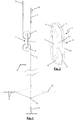
- a Jacquard machine comprises at least two rows of hooks (24), and at least two knives, which each move up and down in counterphase opposite a row of hooks (24) and do or do not take the corresponding hooks (24) along with them.
- FIG. 1 two hooks (24) are shown, which each form part of a respective row of hooks (24). These two hooks (24) form a so-called set of hooks.
- these two hooks (24) are connected to an upper pulley cord (2), which has been passed around an upper pulley wheel (6) of a pulley (1).
- a lower pulley cord (2') Around the lower pulley wheel (6') of this pulley (1) a lower pulley cord (2') has been passed.
- This lower pulley cord (2') is at a first end connected to one or more heddles (23), which are provided with an opening (heddle eye), through which runs a warp thread (22), for adjustment of the position of this warp thread (22).
- Such a heddle (23) is spring-loaded (25).
- the lower pulley cord (2') is held at a well-defined position (26) in the Jacquard machine.
- This position (26) can be a fixed position, or can be adjustable, this, for example, with the aid of a control profile.
- the height of the heddle eyes of the Jacquard heddles (23) can be adjusted without the entire Jacquard machine having to be adjusted in height.
- a pulley mechanism can further also comprise other components, such as, for example, reversing rollers, around which a pulley cord (2, 2') has been passed, harness cords, etc.
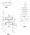
- the pulley (1) from this pulley mechanism comprises the said pulley wheels (6, 6'), which are each fitted rotatably around a shaft (3).
- the pulley (1) further comprises flank bodies (5), which are arranged on both sides of the pulley wheels (6, 6') and which form part of a housing (4) for the pulley (1).
- these flank bodies (5) can be provided with wings (12), which extend between the pulley wheels (6, 6') in order to better guide a cord (2) passed around a pulley wheel (6, 6').
- These wings (12) can possibly also be provided as separate parts of the housing (4).
- the shafts (3) and the flank bodies (5) are mutually connected in such a way that the shafts (3) axially secure the flank bodies (5).
- the shafts (3) are provided with cavities (7, 10, 11) and any projecting portions, examples of which are given below with some specific embodiments.
- the shafts (3) of a pulley (1) according to the invention preferably have a higher resistance to wear than the pulley wheels (6, 6').
- the shafts (3) can for this purpose preferentially be produced from metal.
- This can advantageously be a material which is also used, for example, in hydraulic applications, in precision instruments, in control apparatus etc., so that the availability thereof is high and hence a high-quality product can be realized for a limited cost.
- stainless steel types from the AISI 300 series for example, such as AISI type 302, 304, 310, 316, etc., preferably in a state denoted by "full hard" are suitable materials for such a shaft (3).
- such a shaft (3) is produced by a drawing process.
- such a shaft (3) is preferably provided with a porous coating.
- a coating can be, for example, tungsten disulfide.
- the pulley wheels (6, 6') are preferably produced from plastic.
- plastic polyoxymethylene (POM) or a nylon (PA6 or PA6.6) can be considered, but for a more durable solution polyether ether ketone (PEEK) can also be considered.
- POM polyoxymethylene
- PA6 or PA6.6 nylon
- PEEK polyether ether ketone
- such a pulley wheel (6, 6') can also be provided with a labyrinth seal (14a, 14b), of which examples are further given in the specific embodiments.
- such a pulley wheel (6, 6') is preferably provided with a slot (13), as shown in Figures 2 and 5 , in order to guide the pulley cord (2) which has been passed around here.
- the housing (4) of a pulley (1) according to the invention is preferably produced from plastic.
- Polyamide 6.6 whether or not in combination with glass fibre, for example 30% glass fibre, is for example a suitable material for such a housing (4), but also other materials, such as polyamide 6 and polyoxymethylene (POM), qualify as the base plastic.
- the housing (4) has been produced by injection moulding. This allows a cheaper choice of material.
- At least one flank body (5) of a pulley (1) preferably comprises a groove (15), as shown in the particular embodiment in Figure 2 , for the securement of a pulley cord (2, 2') passed around a pulley wheel (6, 6').
- This groove preferably extends transversely to the longitudinal direction of the corresponding shaft (3) over the whole of the flank body (5) and here preferably runs, starting from one side of the flank body (5), through to the opposite side thereof.
- This groove preferably assumes the same curved shape in which the pulley cord (2, 2') is passed around the pulley wheel (6, 6').
- the housing (4) is further preferably of two-part design, wherein each flank body (5) forms part of a respective part of the two-part housing (4).
- the two parts of the two-part housing (4) are preferably virtually identical, so that exchange of the two parts does not affect the assembly.
- These two parts are further preferably mutually connected using a press fit (27a, 27b) and/or a click connection, so that an assembly is possible without bonding, heating or extra fastening means, etc.
- a press fit 27a, 27b
- the flank bodies (5) are provided with corresponding cavities (27a) and grooves (27b).
- the shown shaft (3) is a circular cylinder having in the centre a concentric cylindrical cavity (7).
- the flank bodies (5) are each provided with a projection (8), which, via the corresponding access opening (9), engages in the cavity (7) of the shaft (3), as can be seen in Figures 4 and 5 .
- the cavity (7) of the shaft (3) extends through the shaft (3), and given that the shaft (3) has a uniform cross section, this can be produced particularly accurately by drawing or extrusion.
- the projections (8) of the flank bodies (5) extend up to a distance apart in the cavity (7) of the shaft (3).
- the projections (8) of the flank bodies (5) together extend over the full length of the cavity (7) of the shaft (3), wherein the projections (8) meet in the centre of this cavity (7).
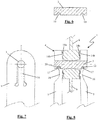
- the shaft (3) is provided at the underside with two notches (10), namely one per flank body (5).
- an elastic part (16) is provided, which can elastically deflect with respect to the rest of the flank body (5).
- This elastic part is provided at the top with a tooth (17), which is fittable in the corresponding notch (10) in the shaft (3).
- a single notch (10) is provided per flank body.
- a plurality of cavities (10) could also be provided per flank body (5), wherein the flank bodies (5) are provided with corresponding teeth (17).
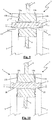
- the shaft (3) is provided with a radial constriction (11) for each flank body (5).
- the flank bodies (5) prior to fastening thereof, are provided with material (19) which, as can be seen in Figure 10 , following pressing, transforms into a radial rib (18), which engages in the corresponding radial constriction (11).
- the thus formed radial ribs (18) engage positively in the corresponding constrictions (11), so that the flank bodies (5) are axially secured by the shaft (3).
- the shaft (3) can also be provided with a local cavity instead of the shown radial constriction (11).
- a plurality of local cavities can be provided spread over the periphery of the shaft (3), into which cavities material of the flank bodies (5) is pressed analogously by pressing.
- the shaft (3) is provided at a first end, analogously to the third shown embodiment, with a radial constriction (11), in which a radial rib (18) of the corresponding flank body (5) engages by pressing, this with the advantages described above.
- the shaft (3) is provided with a toothing (20), in which material of the corresponding flank body (5) also engages positively, by pressing.
- the toothing in this case provides for an extra radial securement of the shaft.
- the pulley wheel (6) is respectively laterally provided with grooves (14a), in which a rib (14b) of the flank bodies (5) engages.
- grooves (14a) in which a rib (14b) of the flank bodies (5) engages.
- a labyrinth seal (14a, 14b) which is provided to keep lubricants in the space between the shaft (3), flank bodies (5) and pulley wheel (6).
- Such a labyrinth seal can also consist of a plurality of and/or more complex groove-rib combinations.
- the shown shafts (3) are respectively of one-part design. Alternatively, these could also be realized in multipart design, for example if this simplifies the production thereof or if, with differing materials, differing properties are assigned to these parts.
Landscapes
- Engineering & Computer Science (AREA)
- Textile Engineering (AREA)
- Pulleys (AREA)
Claims (15)
- Flashenzug (1) zum Einbau in einen Flaschenzugmechanismus einer Jacquard-Maschine, umfassend- eine Welle (3),- ein Gehäuse (4), das zwei Flankenkörper (5) umfasst, die die Welle (3) befestigen, so dass sich diese Welle (3) im Wesentlichen zwischen den Flankenkörpern (5) erstreckt und so dass die Welle (3) die Flankenkörper (5) in beiden axialen Richtungen axial sichert,- und eine Rolle (6, 6'), die zwischen den beiden Flankenkörpern (5) angeordnet ist, so dass sie direkt um die Welle (3) drehbar ist,dadurch gekennzeichnet, dass die Welle (3) mit mindestens einem Hohlraum (7, 10, 11) für das axiale Sichern der Flankenkörper (5) in beiden axialen Richtungen versehen ist, wobei der Hohlraum (7, 10, 11) einen leeren Raum innerhalb der Welle bildet, wobei der leere Raum an mindestens zwei gegenüberliegenden Seiten begrenzt ist.
- Flashenzug (1) nach Anspruch 1, dadurch gekennzeichnet, dass die Welle (3) an ihren beiden Enden eine Zugangsöffnung (9) zu dem Hohlraum (7) in der Welle (3) umfasst und dass die Flankenkörper (5) über diese Zugangsöffnung (9) in dem jeweiligen Hohlraum (7) eingreifen.
- Flashenzug (1) nach einem der Ansprüche 2, dadurch gekennzeichnet, dass die Welle (3) mit einem Hohlraum (7) versehen ist, der sich als der Hohlraum (7) durch die Welle (3) erstreckt.
- Flashenzug (1) nach einem der vorhergehenden Ansprüche, dadurch gekennzeichnet, dass die Flankenkörper (5) die Welle (3) reibungsmäßig festklemmen.
- Flashenzug (1) nach einem der Ansprüche 2 oder 3 und Anspruch 4, dadurch gekennzeichnet, dass jeder Flankenkörper (5) einen Vorsprung (8) umfasst, der über die jeweilige Zugangsöffnung (9) in dem jeweiligen Hohlraum (7) eingreift, um die Welle (3) reibungsmäßig festzuklemmen.
- Flashenzug (1) nach Anspruch 5, dadurch gekennzeichnet, dass die Vorsprünge (8) der Flankenkörper (5) zusammen die Welle (3) über nahezu die gesamte Innenfläche dieser Welle (3) festklemmen.
- Flashenzug (1) nach Anspruch 5 oder 6, dadurch gekennzeichnet, dass die Vorsprünge (8) der Flankenkörper (5) mit einer hohlen Auslegung ausgeführt sind.
- Flashenzug (1) nach einem der vorhergehenden Ansprüche, dadurch gekennzeichnet, dass die Welle (3) mit einer radialen Einschnürung (11) als dem Hohlraum (7, 10, 11) versehen ist.
- Flashenzug (1) nach einem der vorhergehenden Ansprüche, dadurch gekennzeichnet, dass die Flankenkörper (5) die Welle (3) radial sichern.
- Flashenzug (1) nach einem der vorhergehenden Ansprüche, dadurch gekennzeichnet, dass die Welle (3) über Presspassung mit den Flankenkörpern (5) verbunden ist.
- Flashenzug (1) nach einem der vorhergehenden Ansprüche, dadurch gekennzeichnet, dass die Welle (3) unter Verwendung einer porösen Beschichtung beschichtet ist.
- Flashenzug (1) nach einem der vorhergehenden Ansprüche, dadurch gekennzeichnet, dass die Welle (3) verschleißfester als die Rolle (6, 6') ist.
- Flashenzug (1) nach einem der vorhergehenden Ansprüche, dadurch gekennzeichnet, dass die Rolle (6, 6') und die Flankenkörper (5) mit jeweiligen Nuten (14a) und Rippen (14b) versehen sind, die zusammen eine Labyrinthdichtung (14a, 14b) bilden.
- Flaschenzugmechanismus für eine Jacquard-Maschine, dadurch gekennzeichnet, dass dieser Flaschenzugmechanismus ein Flashenzug (1) nach einem der vorhergehenden Ansprüche umfasst.
- Jacquard-Maschine, dadurch gekennzeichnet, dass diese Jacquard-Maschine einen Flaschenzugmechanismus nach Anspruch 14 umfasst.
Applications Claiming Priority (2)
| Application Number | Priority Date | Filing Date | Title |
|---|---|---|---|
| BE20155033A BE1022692A9 (nl) | 2015-01-22 | 2015-01-22 | Takel voor inbouw in een takelinrichting van een jacquardmachine |
| PCT/IB2016/050271 WO2016116873A1 (en) | 2015-01-22 | 2016-01-20 | Pulley for installation in a pulley mechanism of a jacquard machine |
Publications (2)
| Publication Number | Publication Date |
|---|---|
| EP3247828A1 EP3247828A1 (de) | 2017-11-29 |
| EP3247828B1 true EP3247828B1 (de) | 2021-03-03 |
Family
ID=53058956
Family Applications (1)
| Application Number | Title | Priority Date | Filing Date |
|---|---|---|---|
| EP16704476.7A Active EP3247828B1 (de) | 2015-01-22 | 2016-01-20 | Riemenscheibe zur installation in einem riemenscheibenantrieb einer jacquardmaschine |
Country Status (7)
| Country | Link |
|---|---|
| US (1) | US10358747B2 (de) |
| EP (1) | EP3247828B1 (de) |
| JP (2) | JP7048316B2 (de) |
| KR (1) | KR102582828B1 (de) |
| CN (1) | CN107109718B (de) |
| BE (1) | BE1022692A9 (de) |
| WO (1) | WO2016116873A1 (de) |
Cited By (1)
| Publication number | Priority date | Publication date | Assignee | Title |
|---|---|---|---|---|
| EP4592434A1 (de) | 2024-01-26 | 2025-07-30 | Vandewiele NV | Rollenzug zum einbau in einen flaschenzug einer jacquardmaschine |
Families Citing this family (4)
| Publication number | Priority date | Publication date | Assignee | Title |
|---|---|---|---|---|
| EP3112509A1 (de) * | 2015-07-02 | 2017-01-04 | NV Michel van de Wiele | Verbindungselement zum verbinden von elementen eines fachbildungsmechanismus für eine webmaschine |
| EP3739092B1 (de) * | 2019-05-13 | 2023-07-19 | Stäubli Italia S.p.A. | Fachbildungsvorrichtung zum etikettieren von webkanten oder geweben auf einer webmaschine und verfahren zur anpassung solch einer fachbildungsvorrichtung |
| CN116837513B (zh) * | 2023-06-02 | 2025-11-21 | 武汉纺织大学 | 提花织机双动程提综装置及其使用方法 |
| CN119465471A (zh) * | 2024-12-24 | 2025-02-18 | 诸暨瑞铂贸易有限公司 | 一种运行稳定的电子提花机凸轮转动机构 |
Family Cites Families (15)
| Publication number | Priority date | Publication date | Assignee | Title |
|---|---|---|---|---|
| CH367452A (de) * | 1958-04-19 | 1963-02-15 | Rueti Ag Maschf | Jacquardmaschine mit Doppelrollenelementen |
| AT217387B (de) * | 1959-05-15 | 1961-09-25 | Rueti Ag Maschf | Doppelrollenelement für Jacquard-Maschinen |
| IT1250280B (it) * | 1991-08-06 | 1995-04-07 | Skf Ind Spa | Dispositivo tendifilo con cuscinetti volventi |
| JPH0527066U (ja) * | 1991-09-20 | 1993-04-06 | 村田機械株式会社 | ジヤカードの通糸吊下装置 |
| DE69517107T2 (de) * | 1994-06-22 | 2000-12-21 | N.V. Michel Van De Wiele, Kortrijk | Vorrichtung zur Fachbildungsmechanismenwahl durch Biegeelemente |
| EP0807702A1 (de) * | 1996-05-15 | 1997-11-19 | Sulzer RàTi Ag | Einrichtung zum Befestigen eines Körpers und Schafttrieb mit einer derartigen Einrichtung |
| WO1998045517A1 (de) * | 1997-04-09 | 1998-10-15 | Textilma Ag | Webmaschine mit pneumatischer schussfadeneintragung |
| BE1011711A5 (nl) * | 1998-01-19 | 1999-12-07 | Wiele Michel Nv Van De | Gaapvormingsinrichting voor het individueel sturen van de kettingdraden van een weefmachine. |
| BE1013353A5 (nl) * | 2000-03-17 | 2001-12-04 | Wiele Michel Van De Nv | Hakenselectie-inrichting voor een gaapvormingsinrichting voor een weefmachine. |
| BE1016559A4 (nl) * | 2005-03-21 | 2007-01-09 | Wiele Michel Van De Nv | Jacquardinrichting. |
| CN201149043Y (zh) * | 2008-01-24 | 2008-11-12 | 曹光斗 | 联轴器中间节新型结构 |
| CN201686798U (zh) * | 2010-05-13 | 2010-12-29 | 浙江奇汇电子提花机有限公司 | 一种电子提花机电磁阀组件的滑轮支架结构 |
| BE1021506B1 (nl) | 2012-11-19 | 2015-12-03 | Nv Michel Van De Wiele | Module geschikt voor inbouw in een jaquardmachine |
| CN203229633U (zh) * | 2013-03-05 | 2013-10-09 | 上虞市华能纺器厂 | 带围板防护装置的织布提花机滑轮 |
| CN203624711U (zh) * | 2013-12-23 | 2014-06-04 | 武汉力为汽车电气有限公司 | 收线机多型线轴夹具 |
-
2015
- 2015-01-22 BE BE20155033A patent/BE1022692A9/nl not_active IP Right Cessation
-
2016
- 2016-01-20 US US15/545,542 patent/US10358747B2/en active Active
- 2016-01-20 EP EP16704476.7A patent/EP3247828B1/de active Active
- 2016-01-20 JP JP2017539354A patent/JP7048316B2/ja not_active Expired - Fee Related
- 2016-01-20 WO PCT/IB2016/050271 patent/WO2016116873A1/en not_active Ceased
- 2016-01-20 CN CN201680004868.6A patent/CN107109718B/zh active Active
- 2016-01-20 KR KR1020177023211A patent/KR102582828B1/ko active Active
-
2020
- 2020-09-30 JP JP2020165676A patent/JP7101222B2/ja active Active
Non-Patent Citations (1)
| Title |
|---|
| None * |
Cited By (1)
| Publication number | Priority date | Publication date | Assignee | Title |
|---|---|---|---|---|
| EP4592434A1 (de) | 2024-01-26 | 2025-07-30 | Vandewiele NV | Rollenzug zum einbau in einen flaschenzug einer jacquardmaschine |
Also Published As
| Publication number | Publication date |
|---|---|
| CN107109718B (zh) | 2020-06-09 |
| JP2018506655A (ja) | 2018-03-08 |
| BE1022692A1 (nl) | 2016-07-26 |
| BE1022692B1 (nl) | 2016-07-26 |
| KR102582828B1 (ko) | 2023-09-25 |
| US10358747B2 (en) | 2019-07-23 |
| KR20170104610A (ko) | 2017-09-15 |
| JP7101222B2 (ja) | 2022-07-14 |
| CN107109718A (zh) | 2017-08-29 |
| WO2016116873A1 (en) | 2016-07-28 |
| JP2021004439A (ja) | 2021-01-14 |
| BE1022692A9 (nl) | 2016-10-07 |
| US20180044821A1 (en) | 2018-02-15 |
| JP7048316B2 (ja) | 2022-04-05 |
| EP3247828A1 (de) | 2017-11-29 |
Similar Documents
| Publication | Publication Date | Title |
|---|---|---|
| EP3247828B1 (de) | Riemenscheibe zur installation in einem riemenscheibenantrieb einer jacquardmaschine | |
| CN110030311B (zh) | 弹簧套筒、缸体、活塞缸单元及制造活塞缸单元的方法 | |
| CN104903504A (zh) | 旋转编织机 | |
| KR20190002679A (ko) | 원형 직조기 및 중공 프로파일형 직물을 제조하는 방법 | |
| JP2017101370A (ja) | 織機の伝動装置 | |
| CN1847700B (zh) | 把输入轴第一旋转运动调节成输出轴第二旋转运动的装置 | |
| CN103422214B (zh) | 梭口成型装置及安装有该装置的织布机 | |
| CN223866876U (zh) | 用于安装在提花机的滑轮机构中的滑轮组 | |
| EP4592434A1 (de) | Rollenzug zum einbau in einen flaschenzug einer jacquardmaschine | |
| KR100517042B1 (ko) | 직기에서의 식서형성장치 | |
| KR100893949B1 (ko) | 원형직기 | |
| CN107923086B (zh) | 织梭 | |
| EP1989346B1 (de) | Litze für eine webmaschine, webmaschine mit einer oder mehreren derartigen litzen und verfahren zur herstellung einer derartigen litze | |
| CN203614696U (zh) | 用于超大型圆织机的凸轮 | |
| CN101245526B (zh) | 圆编机大盘及其主齿轮组合装置 | |
| CN104831468A (zh) | 经编针织机的部件 | |
| CN218809514U (zh) | 一种线筒放置装置 | |
| CN109338570A (zh) | 圆织机大凸轮与综丝杆起落组件的传动机构 | |
| CN117449024A (zh) | 高强耐磨针织物及其制备工艺 | |
| US486336A (en) | James hill | |
| KR200172963Y1 (ko) | 도비기용 와이어 가이드 휠 | |
| CN100572637C (zh) | 经编机 | |
| CN101365836A (zh) | 用于形成纱罗织物的抗磨损装置 | |
| KR20150003240U (ko) | 자카드직기용 종광 | |
| KR101722619B1 (ko) | 끊어지지 않는 복합소재 섬유층을 포함하는 부시 베어링 및 슬라이딩 베어링 제조장치 |
Legal Events
| Date | Code | Title | Description |
|---|---|---|---|
| STAA | Information on the status of an ep patent application or granted ep patent |
Free format text: STATUS: THE INTERNATIONAL PUBLICATION HAS BEEN MADE |
|
| PUAI | Public reference made under article 153(3) epc to a published international application that has entered the european phase |
Free format text: ORIGINAL CODE: 0009012 |
|
| STAA | Information on the status of an ep patent application or granted ep patent |
Free format text: STATUS: REQUEST FOR EXAMINATION WAS MADE |
|
| 17P | Request for examination filed |
Effective date: 20170711 |
|
| AK | Designated contracting states |
Kind code of ref document: A1 Designated state(s): AL AT BE BG CH CY CZ DE DK EE ES FI FR GB GR HR HU IE IS IT LI LT LU LV MC MK MT NL NO PL PT RO RS SE SI SK SM TR |
|
| AX | Request for extension of the european patent |
Extension state: BA ME |
|
| DAX | Request for extension of the european patent (deleted) | ||
| RAV | Requested validation state of the european patent: fee paid |
Extension state: MA Effective date: 20170713 |
|
| STAA | Information on the status of an ep patent application or granted ep patent |
Free format text: STATUS: EXAMINATION IS IN PROGRESS |
|
| 17Q | First examination report despatched |
Effective date: 20190529 |
|
| GRAP | Despatch of communication of intention to grant a patent |
Free format text: ORIGINAL CODE: EPIDOSNIGR1 |
|
| STAA | Information on the status of an ep patent application or granted ep patent |
Free format text: STATUS: GRANT OF PATENT IS INTENDED |
|
| INTG | Intention to grant announced |
Effective date: 20201030 |
|
| RAP1 | Party data changed (applicant data changed or rights of an application transferred) |
Owner name: VANDEWIELE NV |
|
| GRAS | Grant fee paid |
Free format text: ORIGINAL CODE: EPIDOSNIGR3 |
|
| GRAA | (expected) grant |
Free format text: ORIGINAL CODE: 0009210 |
|
| STAA | Information on the status of an ep patent application or granted ep patent |
Free format text: STATUS: THE PATENT HAS BEEN GRANTED |
|
| AK | Designated contracting states |
Kind code of ref document: B1 Designated state(s): AL AT BE BG CH CY CZ DE DK EE ES FI FR GB GR HR HU IE IS IT LI LT LU LV MC MK MT NL NO PL PT RO RS SE SI SK SM TR |
|
| REG | Reference to a national code |
Ref country code: GB Ref legal event code: FG4D |
|
| REG | Reference to a national code |
Ref country code: AT Ref legal event code: REF Ref document number: 1367297 Country of ref document: AT Kind code of ref document: T Effective date: 20210315 Ref country code: CH Ref legal event code: EP |
|
| REG | Reference to a national code |
Ref country code: DE Ref legal event code: R096 Ref document number: 602016053512 Country of ref document: DE |
|
| REG | Reference to a national code |
Ref country code: CH Ref legal event code: NV Representative=s name: VALIPAT S.A. C/O BOVARD SA NEUCHATEL, CH Ref country code: IE Ref legal event code: FG4D |
|
| REG | Reference to a national code |
Ref country code: LT Ref legal event code: MG9D |
|
| PG25 | Lapsed in a contracting state [announced via postgrant information from national office to epo] |
Ref country code: NO Free format text: LAPSE BECAUSE OF FAILURE TO SUBMIT A TRANSLATION OF THE DESCRIPTION OR TO PAY THE FEE WITHIN THE PRESCRIBED TIME-LIMIT Effective date: 20210603 Ref country code: FI Free format text: LAPSE BECAUSE OF FAILURE TO SUBMIT A TRANSLATION OF THE DESCRIPTION OR TO PAY THE FEE WITHIN THE PRESCRIBED TIME-LIMIT Effective date: 20210303 Ref country code: HR Free format text: LAPSE BECAUSE OF FAILURE TO SUBMIT A TRANSLATION OF THE DESCRIPTION OR TO PAY THE FEE WITHIN THE PRESCRIBED TIME-LIMIT Effective date: 20210303 Ref country code: GR Free format text: LAPSE BECAUSE OF FAILURE TO SUBMIT A TRANSLATION OF THE DESCRIPTION OR TO PAY THE FEE WITHIN THE PRESCRIBED TIME-LIMIT Effective date: 20210604 Ref country code: BG Free format text: LAPSE BECAUSE OF FAILURE TO SUBMIT A TRANSLATION OF THE DESCRIPTION OR TO PAY THE FEE WITHIN THE PRESCRIBED TIME-LIMIT Effective date: 20210603 Ref country code: LT Free format text: LAPSE BECAUSE OF FAILURE TO SUBMIT A TRANSLATION OF THE DESCRIPTION OR TO PAY THE FEE WITHIN THE PRESCRIBED TIME-LIMIT Effective date: 20210303 |
|
| REG | Reference to a national code |
Ref country code: NL Ref legal event code: MP Effective date: 20210303 |
|
| PG25 | Lapsed in a contracting state [announced via postgrant information from national office to epo] |
Ref country code: SE Free format text: LAPSE BECAUSE OF FAILURE TO SUBMIT A TRANSLATION OF THE DESCRIPTION OR TO PAY THE FEE WITHIN THE PRESCRIBED TIME-LIMIT Effective date: 20210303 Ref country code: PL Free format text: LAPSE BECAUSE OF FAILURE TO SUBMIT A TRANSLATION OF THE DESCRIPTION OR TO PAY THE FEE WITHIN THE PRESCRIBED TIME-LIMIT Effective date: 20210303 Ref country code: RS Free format text: LAPSE BECAUSE OF FAILURE TO SUBMIT A TRANSLATION OF THE DESCRIPTION OR TO PAY THE FEE WITHIN THE PRESCRIBED TIME-LIMIT Effective date: 20210303 Ref country code: LV Free format text: LAPSE BECAUSE OF FAILURE TO SUBMIT A TRANSLATION OF THE DESCRIPTION OR TO PAY THE FEE WITHIN THE PRESCRIBED TIME-LIMIT Effective date: 20210303 |
|
| PG25 | Lapsed in a contracting state [announced via postgrant information from national office to epo] |
Ref country code: NL Free format text: LAPSE BECAUSE OF FAILURE TO SUBMIT A TRANSLATION OF THE DESCRIPTION OR TO PAY THE FEE WITHIN THE PRESCRIBED TIME-LIMIT Effective date: 20210303 |
|
| PG25 | Lapsed in a contracting state [announced via postgrant information from national office to epo] |
Ref country code: SM Free format text: LAPSE BECAUSE OF FAILURE TO SUBMIT A TRANSLATION OF THE DESCRIPTION OR TO PAY THE FEE WITHIN THE PRESCRIBED TIME-LIMIT Effective date: 20210303 Ref country code: EE Free format text: LAPSE BECAUSE OF FAILURE TO SUBMIT A TRANSLATION OF THE DESCRIPTION OR TO PAY THE FEE WITHIN THE PRESCRIBED TIME-LIMIT Effective date: 20210303 Ref country code: CZ Free format text: LAPSE BECAUSE OF FAILURE TO SUBMIT A TRANSLATION OF THE DESCRIPTION OR TO PAY THE FEE WITHIN THE PRESCRIBED TIME-LIMIT Effective date: 20210303 |
|
| PG25 | Lapsed in a contracting state [announced via postgrant information from national office to epo] |
Ref country code: PT Free format text: LAPSE BECAUSE OF FAILURE TO SUBMIT A TRANSLATION OF THE DESCRIPTION OR TO PAY THE FEE WITHIN THE PRESCRIBED TIME-LIMIT Effective date: 20210705 Ref country code: SK Free format text: LAPSE BECAUSE OF FAILURE TO SUBMIT A TRANSLATION OF THE DESCRIPTION OR TO PAY THE FEE WITHIN THE PRESCRIBED TIME-LIMIT Effective date: 20210303 Ref country code: RO Free format text: LAPSE BECAUSE OF FAILURE TO SUBMIT A TRANSLATION OF THE DESCRIPTION OR TO PAY THE FEE WITHIN THE PRESCRIBED TIME-LIMIT Effective date: 20210303 Ref country code: IS Free format text: LAPSE BECAUSE OF FAILURE TO SUBMIT A TRANSLATION OF THE DESCRIPTION OR TO PAY THE FEE WITHIN THE PRESCRIBED TIME-LIMIT Effective date: 20210703 |
|
| REG | Reference to a national code |
Ref country code: DE Ref legal event code: R097 Ref document number: 602016053512 Country of ref document: DE |
|
| PLBE | No opposition filed within time limit |
Free format text: ORIGINAL CODE: 0009261 |
|
| STAA | Information on the status of an ep patent application or granted ep patent |
Free format text: STATUS: NO OPPOSITION FILED WITHIN TIME LIMIT |
|
| PG25 | Lapsed in a contracting state [announced via postgrant information from national office to epo] |
Ref country code: DK Free format text: LAPSE BECAUSE OF FAILURE TO SUBMIT A TRANSLATION OF THE DESCRIPTION OR TO PAY THE FEE WITHIN THE PRESCRIBED TIME-LIMIT Effective date: 20210303 Ref country code: AL Free format text: LAPSE BECAUSE OF FAILURE TO SUBMIT A TRANSLATION OF THE DESCRIPTION OR TO PAY THE FEE WITHIN THE PRESCRIBED TIME-LIMIT Effective date: 20210303 Ref country code: ES Free format text: LAPSE BECAUSE OF FAILURE TO SUBMIT A TRANSLATION OF THE DESCRIPTION OR TO PAY THE FEE WITHIN THE PRESCRIBED TIME-LIMIT Effective date: 20210303 |
|
| 26N | No opposition filed |
Effective date: 20211206 |
|
| PG25 | Lapsed in a contracting state [announced via postgrant information from national office to epo] |
Ref country code: SI Free format text: LAPSE BECAUSE OF FAILURE TO SUBMIT A TRANSLATION OF THE DESCRIPTION OR TO PAY THE FEE WITHIN THE PRESCRIBED TIME-LIMIT Effective date: 20210303 |
|
| PG25 | Lapsed in a contracting state [announced via postgrant information from national office to epo] |
Ref country code: IS Free format text: LAPSE BECAUSE OF FAILURE TO SUBMIT A TRANSLATION OF THE DESCRIPTION OR TO PAY THE FEE WITHIN THE PRESCRIBED TIME-LIMIT Effective date: 20210703 |
|
| PG25 | Lapsed in a contracting state [announced via postgrant information from national office to epo] |
Ref country code: MC Free format text: LAPSE BECAUSE OF FAILURE TO SUBMIT A TRANSLATION OF THE DESCRIPTION OR TO PAY THE FEE WITHIN THE PRESCRIBED TIME-LIMIT Effective date: 20210303 |
|
| GBPC | Gb: european patent ceased through non-payment of renewal fee |
Effective date: 20220120 |
|
| PG25 | Lapsed in a contracting state [announced via postgrant information from national office to epo] |
Ref country code: LU Free format text: LAPSE BECAUSE OF NON-PAYMENT OF DUE FEES Effective date: 20220120 Ref country code: GB Free format text: LAPSE BECAUSE OF NON-PAYMENT OF DUE FEES Effective date: 20220120 |
|
| PG25 | Lapsed in a contracting state [announced via postgrant information from national office to epo] |
Ref country code: IE Free format text: LAPSE BECAUSE OF NON-PAYMENT OF DUE FEES Effective date: 20220120 |
|
| REG | Reference to a national code |
Ref country code: AT Ref legal event code: UEP Ref document number: 1367297 Country of ref document: AT Kind code of ref document: T Effective date: 20210303 |
|
| PGFP | Annual fee paid to national office [announced via postgrant information from national office to epo] |
Ref country code: CH Payment date: 20230119 Year of fee payment: 8 Ref country code: AT Payment date: 20230120 Year of fee payment: 8 |
|
| PGFP | Annual fee paid to national office [announced via postgrant information from national office to epo] |
Ref country code: IT Payment date: 20230120 Year of fee payment: 8 Ref country code: DE Payment date: 20230123 Year of fee payment: 8 Ref country code: BE Payment date: 20230119 Year of fee payment: 8 |
|
| P01 | Opt-out of the competence of the unified patent court (upc) registered |
Effective date: 20230424 |
|
| PG25 | Lapsed in a contracting state [announced via postgrant information from national office to epo] |
Ref country code: HU Free format text: LAPSE BECAUSE OF FAILURE TO SUBMIT A TRANSLATION OF THE DESCRIPTION OR TO PAY THE FEE WITHIN THE PRESCRIBED TIME-LIMIT; INVALID AB INITIO Effective date: 20160120 |
|
| PG25 | Lapsed in a contracting state [announced via postgrant information from national office to epo] |
Ref country code: MK Free format text: LAPSE BECAUSE OF FAILURE TO SUBMIT A TRANSLATION OF THE DESCRIPTION OR TO PAY THE FEE WITHIN THE PRESCRIBED TIME-LIMIT Effective date: 20210303 Ref country code: CY Free format text: LAPSE BECAUSE OF FAILURE TO SUBMIT A TRANSLATION OF THE DESCRIPTION OR TO PAY THE FEE WITHIN THE PRESCRIBED TIME-LIMIT Effective date: 20210303 |
|
| VS25 | Lapsed in a validation state [announced via postgrant information from nat. office to epo] |
Ref country code: MA Free format text: LAPSE BECAUSE OF FAILURE TO SUBMIT A TRANSLATION OF THE DESCRIPTION OR TO PAY THE FEE WITHIN THE PRESCRIBED TIME-LIMIT Effective date: 20210303 |
|
| REG | Reference to a national code |
Ref country code: DE Ref legal event code: R119 Ref document number: 602016053512 Country of ref document: DE |
|
| REG | Reference to a national code |
Ref country code: CH Ref legal event code: PL |
|
| REG | Reference to a national code |
Ref country code: AT Ref legal event code: MM01 Ref document number: 1367297 Country of ref document: AT Kind code of ref document: T Effective date: 20240120 |
|
| PG25 | Lapsed in a contracting state [announced via postgrant information from national office to epo] |
Ref country code: MT Free format text: LAPSE BECAUSE OF FAILURE TO SUBMIT A TRANSLATION OF THE DESCRIPTION OR TO PAY THE FEE WITHIN THE PRESCRIBED TIME-LIMIT Effective date: 20210303 |
|
| PG25 | Lapsed in a contracting state [announced via postgrant information from national office to epo] |
Ref country code: DE Free format text: LAPSE BECAUSE OF NON-PAYMENT OF DUE FEES Effective date: 20240801 |
|
| PG25 | Lapsed in a contracting state [announced via postgrant information from national office to epo] |
Ref country code: BE Free format text: LAPSE BECAUSE OF NON-PAYMENT OF DUE FEES Effective date: 20240131 |
|
| PG25 | Lapsed in a contracting state [announced via postgrant information from national office to epo] |
Ref country code: CH Free format text: LAPSE BECAUSE OF NON-PAYMENT OF DUE FEES Effective date: 20240131 |
|
| PG25 | Lapsed in a contracting state [announced via postgrant information from national office to epo] |
Ref country code: AT Free format text: LAPSE BECAUSE OF NON-PAYMENT OF DUE FEES Effective date: 20240120 |
|
| PG25 | Lapsed in a contracting state [announced via postgrant information from national office to epo] |
Ref country code: DE Free format text: LAPSE BECAUSE OF NON-PAYMENT OF DUE FEES Effective date: 20240801 Ref country code: CH Free format text: LAPSE BECAUSE OF NON-PAYMENT OF DUE FEES Effective date: 20240131 Ref country code: BE Free format text: LAPSE BECAUSE OF NON-PAYMENT OF DUE FEES Effective date: 20240131 Ref country code: AT Free format text: LAPSE BECAUSE OF NON-PAYMENT OF DUE FEES Effective date: 20240120 |
|
| REG | Reference to a national code |
Ref country code: BE Ref legal event code: MM Effective date: 20240131 |
|
| PG25 | Lapsed in a contracting state [announced via postgrant information from national office to epo] |
Ref country code: IT Free format text: LAPSE BECAUSE OF NON-PAYMENT OF DUE FEES Effective date: 20240120 |
|
| PGFP | Annual fee paid to national office [announced via postgrant information from national office to epo] |
Ref country code: FR Payment date: 20250127 Year of fee payment: 10 |
|
| PGFP | Annual fee paid to national office [announced via postgrant information from national office to epo] |
Ref country code: TR Payment date: 20250113 Year of fee payment: 10 |