EP3247754B1 - Flüssige elektrofotografische tintenzusammensetzung - Google Patents
Flüssige elektrofotografische tintenzusammensetzung Download PDFInfo
- Publication number
- EP3247754B1 EP3247754B1 EP15700721.2A EP15700721A EP3247754B1 EP 3247754 B1 EP3247754 B1 EP 3247754B1 EP 15700721 A EP15700721 A EP 15700721A EP 3247754 B1 EP3247754 B1 EP 3247754B1
- Authority
- EP
- European Patent Office
- Prior art keywords
- resin component
- examples
- printing composition
- lep printing
- melting point
- Prior art date
- Legal status (The legal status is an assumption and is not a legal conclusion. Google has not performed a legal analysis and makes no representation as to the accuracy of the status listed.)
- Active
Links
Images


Classifications
-
- G—PHYSICS
- G03—PHOTOGRAPHY; CINEMATOGRAPHY; ANALOGOUS TECHNIQUES USING WAVES OTHER THAN OPTICAL WAVES; ELECTROGRAPHY; HOLOGRAPHY
- G03G—ELECTROGRAPHY; ELECTROPHOTOGRAPHY; MAGNETOGRAPHY
- G03G9/00—Developers
- G03G9/08—Developers with toner particles
- G03G9/12—Developers with toner particles in liquid developer mixtures
- G03G9/13—Developers with toner particles in liquid developer mixtures characterised by polymer components
- G03G9/131—Developers with toner particles in liquid developer mixtures characterised by polymer components obtained by reactions only involving carbon-to-carbon unsaturated bonds
-
- C—CHEMISTRY; METALLURGY
- C09—DYES; PAINTS; POLISHES; NATURAL RESINS; ADHESIVES; COMPOSITIONS NOT OTHERWISE PROVIDED FOR; APPLICATIONS OF MATERIALS NOT OTHERWISE PROVIDED FOR
- C09D—COATING COMPOSITIONS, e.g. PAINTS, VARNISHES OR LACQUERS; FILLING PASTES; CHEMICAL PAINT OR INK REMOVERS; INKS; CORRECTING FLUIDS; WOODSTAINS; PASTES OR SOLIDS FOR COLOURING OR PRINTING; USE OF MATERIALS THEREFOR
- C09D11/00—Inks
- C09D11/02—Printing inks
- C09D11/10—Printing inks based on artificial resins
- C09D11/106—Printing inks based on artificial resins containing macromolecular compounds obtained by reactions only involving carbon-to-carbon unsaturated bonds
-
- G—PHYSICS
- G03—PHOTOGRAPHY; CINEMATOGRAPHY; ANALOGOUS TECHNIQUES USING WAVES OTHER THAN OPTICAL WAVES; ELECTROGRAPHY; HOLOGRAPHY
- G03G—ELECTROGRAPHY; ELECTROPHOTOGRAPHY; MAGNETOGRAPHY
- G03G15/00—Apparatus for electrographic processes using a charge pattern
- G03G15/06—Apparatus for electrographic processes using a charge pattern for developing
- G03G15/10—Apparatus for electrographic processes using a charge pattern for developing using a liquid developer
-
- G—PHYSICS
- G03—PHOTOGRAPHY; CINEMATOGRAPHY; ANALOGOUS TECHNIQUES USING WAVES OTHER THAN OPTICAL WAVES; ELECTROGRAPHY; HOLOGRAPHY
- G03G—ELECTROGRAPHY; ELECTROPHOTOGRAPHY; MAGNETOGRAPHY
- G03G9/00—Developers
- G03G9/08—Developers with toner particles
- G03G9/12—Developers with toner particles in liquid developer mixtures
- G03G9/13—Developers with toner particles in liquid developer mixtures characterised by polymer components
- G03G9/132—Developers with toner particles in liquid developer mixtures characterised by polymer components obtained otherwise than by reactions only involving carbon-to-carbon unsaturated bonds
Definitions
- Electrophotographic printing processes typically involve creating an image on a photoconductive surface, applying a printing composition having charged particles to the photoconductive surface, such that they selectively bind to the image, and then transferring the charged particles in the form of the image to a print substrate.
- the photoconductive surface is typically on a cylinder and is often termed a photo imaging plate (PIP).
- PIP photo imaging plate
- the photoconductive surface is selectively charged with a latent electrostatic image having image and background areas with different potentials.
- a printing composition comprising charged toner particles in a carrier liquid can be brought into contact with the selectively charged photoconductive surface.
- the charged toner particles adhere to the image areas of the latent image while the background areas remain clean.
- the image is then transferred to a print substrate (e.g. paper) directly or, more commonly, by being first transferred to an intermediate transfer member, which can be a soft swelling blanket, which is often heated to fuse the solid image and evaporate the carrier liquid, and then to the print substrate.
- carrier fluid As used herein, “carrier fluid”, “carrier liquid,” “carrier,” or “carrier vehicle” refers to the fluid in which the resins, pigment particles, colorant, charge directors and other additives can be dispersed to form a liquid electrostatic composition or electrophotographic composition.
- the carrier liquids may include a mixture of a variety of different agents, such as surfactants, co-solvents, viscosity modifiers, and/or other possible ingredients.
- electrostatic ink composition or “liquid electrophotographic composition” generally refers to an ink composition that is typically suitable for use in an electrostatic printing process, sometimes termed an electrophotographic printing process. It may comprise pigment particles, which may comprise a thermoplastic resin.
- co-polymer refers to a polymer that is polymerized from at least two monomers.
- melt flow rate generally refers to the extrusion rate of a resin through an orifice of defined dimensions at a specified temperature and load, usually reported as temperature/load, e.g. 190°C/2.16 kg. Flow rates can be used to differentiate grades or provide a measure of degradation of a material as a result of molding. In the present disclosure, “melt flow rate” is measured per ASTM D1238-04c Standard Test Method for Melt Flow Rates of Thermoplastics by Extrusion Plastometer, as known in the art. If a melt flow rate of a particular polymer or copolymer is specified, unless otherwise stated, it is the melt flow rate for that polymer or copolymer alone, in the absence of any of the other components of the LEP printing composition.
- acidity refers to the mass of potassium hydroxide (KOH) in milligrams that neutralizes one gram of a substance.
- KOH potassium hydroxide
- the acidity of a polymer or copolymer can be measured according to standard techniques, for example as described in ASTM D1386. If the acidity of a particular polymer or copolymer is specified, unless otherwise stated, it is the acidity for that polymer or copolymer alone, in the absence of any of the other components of the LEP printing composition.
- melt viscosity generally refers to the ratio of shear stress to shear rate at a given shear stress or shear rate. Testing is generally performed using a capillary rheometer. A plastic charge is heated in the rheometer barrel and is forced through a die with a plunger. The plunger is pushed either by a constant force or at constant rate depending on the equipment. Measurements are taken once the system has reached steady-state operation. One method used is measuring Brookfield viscosity @ 140°C, units are mPa-s or cPoise, as known in the art. Alternatively, the melt viscosity can be measured using a rheometer, e.g.
- melt viscosity of a particular polymer or copolymer is specified, unless otherwise stated, it is the melt viscosity for that polymer or copolymer alone, in the absence of any of the other components of the LEP printing composition.
- electrostatic printing or “electrophotographic printing” generally refers to the process that provides an image that is transferred from a photo imaging substrate either directly or indirectly via an intermediate transfer member to a print substrate. As such, the image is not substantially absorbed into the photo imaging substrate on which it is applied.
- electrostatic printers or “electrostatic printers” generally refer to those printers capable of performing electrophotographic printing or electrostatic printing, as described above.
- Liquid electrophotographic printing is a specific type of electrophotographic printing where a liquid composition is employed in the electrophotographic process rather than a powder toner.
- An electrostatic printing process may involve subjecting the electrostatic composition to an electric field, e.g. an electric field having a field gradient of 50-400V/ ⁇ m, or more, in some examples 600-900V/ ⁇ m, or more.
- the term "about” is used to provide flexibility to a numerical range endpoint by providing that a given value may be a little above or a little below the endpoint to allow for variation in test methods or apparatus.
- the degree of flexibility of this term can be dictated by the particular variable and would be within the knowledge of those skilled in the art to determine based on experience and the associated description herein.
- wt% values are to be taken as referring to a weight-for-weight (w/w) percentage of solids in the LEP printing composition, and not including the weight of any carrier fluid present.
- pigment is used generally to refer to pigment colorants, magnetic particles, aluminas, silicas, and/or other ceramics or organo-metallics, whether or not such particulates impart color.
- pigment colorants can be used more generally to describe not just pigment colorants, but other pigments such as organometallics, ferrites, ceramics, etc.
- coloured is used to refer to any colour including white and black.
- coloured toner image refers to an image formed from an electrostatic ink.
- An electrostatic ink typically contains a pigment.
- An electrostatic ink may be any known electrostatic ink composition comprising a first resin component comprising an ethylene acrylic acid resin, an ethylene methacrylic acid resin or combinations thereof.
- the electrostatic ink comprises a first resin component comprising an ethylene acrylic acid resin, an ethylene methacrylic acid resin or combinations thereof and a carrier liquid.
- the electrostatic ink also comprises a colourant.
- the electrostatic ink also comprises a charge director and/or a charge adjuvant.
- the first resin component of the electrostatic ink is different to the first resin component of the LEP printing composition.
- the first resin component of the electrostatic ink is the same as to the first resin component of the LEP printing composition.
- the electrostatic ink lacks a second resin component.
- the electrostatic ink may be HP Indigo's Electroink®4.5 ink.
- the LEP printing composition differs from the electrostatic ink in that the LEP printing composition lacks a pigment. In some examples the LEP printing composition differs from the electrostatic ink in that the LEP printing composition contains a second resin component and the electrostatic ink lacks a second resin component.
- melting point is used to refer to melting points of first and second resin components.
- the "melting point" of a first or second resin component can be measured using differential scanning calorimetry and may be determined from the first heat flow minima reached on heating the first or second resin component from -50°C at a rate of 15 °C/min.
- the "melting point" of a first or second resin component can be measured using standard procedures known in the art, for example using the procedure described in ASTM D3418 or the method outlined in the Examples that follow.
- the terms “partially molten”, “partially melt” and “partially melted” are used to refer to an image containing a first and/or a second resin component in which the first or second resin component has been at least partially melted or softened. In the art, this may be determined as when the resin has become tacky.
- the first resin component or second resin component may become partially molten when heated to a temperature approaching its melting point.
- an image comprising a first resin component and/or a second resin component may be considered to be at least partially molten when the image has reached a temperature that is about 20°C or less below the melting point of either the first resin component or the second resin component.
- the image is considered to be at least partially molten when the image has reached a temperature that is about 15°C or less below the melting point of either the first resin component or the second resin component. In some examples, the image is considered to be at least partially molten when the image has reached a temperature that is about 10°C or less below the melting point of either the first resin component or the second resin component. In some examples, the image is considered to be at least partially molten when the image has reached a temperature that is about 5°C or less below the melting point of either the first resin component or the second resin component.
- an image is considered to be at least partially molten when the image has been held at a temperature approaching the melting point of either the first or second resin component for at least 0.5 seconds, in some examples at least 1 second, in some examples at least 5 seconds, in some examples at least 10 seconds.
- the skilled person is able to determine the temperature range at which a first or second resin component will start to soften or partially melt from data obtained from carrying out differential scanning calorimetry (DSC) on a resin sample using the procedure described in ASTM D3418 showing heat flow to the sample over a temperature range covering the melting point of the resin component.
- a graph showing the heat flow to the sample against temperature obtained by DSC will show a broad trough for the melting point of the resin.
- the skilled person understands, at temperatures below the melting point of the resin, determined as described above, but still within the broad trough the resin will be softened or partially molten.
- a liquid electro photographic (LEP) printing composition comprising a first resin component and a second resin component, wherein the melting point of the second resin component is either below the melting point of the first resin component or above the melting point of the first resin component.
- liquid electro photographic (LEP) printing composition may comprise:
- the first resin component may comprise an ethylene acrylic acid resin, an ethylene methacrylic acid resin or combinations thereof.
- the ethylene acrylic acid resins and the ethylene methacrylic acid resins may also be described as ethylene acrylic acid copolymers and ethylene methacrylic acid copolymers.
- the ethylene acrylic acid resin and the ethylene methacrylic acid resin may contain 80 wt% to 99.9 wt% of ethylene and 0.1 wt% to 20 wt% of acrylic or methacrylic acid.
- the first resin component has a melting point within the range of from about 80°C to about 120 °C, in some examples from about 90°C to about 110 °C. In some examples, the first resin component has a melting point within the range of from about 80°C to about 100 °C.
- the melting point of a resin component can be measured using standard procedures known in the art, for example using the procedure described in ASTM D3418.
- Ethylene acrylic acid copolymers and ethylene methacrylic acid copolymers contain acidic side groups.
- the first resin component may contain copolymers having an acidity of 50 mg KOH/g or more, in some examples an acidity of 60 mg KOH/g or more, in some examples an acidity of 70 mg KOH/g or more, in some examples an acidity of 80 mg KOH/g or more, in some examples an acidity of 90 mg KOH/g or more, in some examples an acidity of 100 mg KOH/g or more, in some examples an acidity of 105 mg KOH/g or more, in some examples 110 mg KOH/g or more, in some examples 115 mg KOH/g or more.
- the first resin component containing a resin having acidic side groups may have an acidity of 200 mg KOH/g or less, in some examples 190 mg or less, in some examples 180 mg or less, in some examples 130 mg KOH/g or less, in some examples 120 mg KOH/g or less.
- Acidity of a resin, as measured in mg KOH/g can be measured using standard procedures known in the art, for example using the procedure described in ASTM D1386.
- the first resin component comprising an ethylene acrylic acid copolymer and/or an ethylene methacrylic acid copolymer having acidic side groups, may have a melt flow rate of less than about 120g/10 minutes, in some examples about 110 g/10 minutes or less, in some examples about 100 g/10 minutes or less, in some examples about 90 g/10 minutes or less, in some examples about 80 g/10 minutes or less, in some examples about 70 g/10 minutes or less, in some examples about 60 g/10 minutes or less, in some examples about 50 g/10 minutes or less, in some examples about 40 g/10 minutes or less, in some examples 30 g/10 minutes or less, in some examples 20 g/10 minutes or less, in some examples 10 g/10 minutes or less.
- the first resin component containing an ethylene acrylic acid copolymer and/or an ethylene methacrylic acid copolymer having acidic side groups may have a melt flow rate of about 10 g/10 minutes to about 120 g/10 minutes, in some examples about 10 g/10 minutes to about 70 g/10 minutes, in some examples about 10 g/10 minutes to 40 g/10 minutes, in some examples 20 g/10 minutes to 30 g/10 minutes.
- the ethylene acrylic acid copolymer and/or the ethylene methacrylic acid copolymer having acidic side groups can have a melt flow rate of, in some examples, about 50 g/10 minutes to about 120 g/10 minutes, in some examples 60 g/10 minutes to about 100 g/10 minutes.
- the melt flow rate can be measured using standard procedures known in the art, for example as described in ASTM D1238.
- the acidic side groups may be in free acid form or may be in the form of an anion and associated with one or more counterions, typically metal counterions, e.g. a metal selected from the alkali metals, such as lithium, sodium and potassium, alkali earth metals, such as magnesium or calcium, and transition metals, such as zinc.
- the first resin component selected from ethylene acrylic acid resins, ethylene methacrylic acid resins or combinations thereof may have acidic sides groups which are at least partially neutralized with metal ions (e.g. Zn, Na, Li) such as SURLYN ® ionomers.
- the ethylene acrylic acid copolymers and ethylene methacrylic acid copolymers may be such that either the acrylic or methacrylic acid constitute from 5 wt% to about 25 wt% of the ethylene acrylic acid or ethylene methacrylic acid co-polymer, in some examples from 10 wt% to about 20 wt% of the ethylene acrylic acid or ethylene methacrylic acid co-polymer.
- the first resin component may include two different ethylene acrylic acid and/or ethylene methacrylic acid copolymers having acidic side groups.
- the two copolymers having acidic side groups may have different acidities, which may fall within the ranges mentioned above.
- the resin may include a first copolymer having acidic side groups that has an acidity of from 10 mg KOH/g to 110 mg KOH/g, in some examples 20 mg KOH/g to 110 mg KOH/g, in some examples 30 mg KOH/g to 110 mg KOH/g, in some examples 50 mg KOH/g to 110 mg KOH/g, and a second copolymer having acidic side groups that has an acidity of 110 mg KOH/g to 130 mg KOH/g.
- the first copolymer may be Nucrel 699® (from DuPont).
- the second copolymer may be A-C® 5120 (from Honeywell).
- the ratio of the first copolymer having acidic side groups to the second copolymer having acidic side groups can be from about 10:1 to about 2:1.
- the ratio can be from about 6:1 to about 3:1, in some examples about 4:1.
- the first resin component may include an ethylene acrylic acid and/or an ethylene methacrylic acid copolymer having a melt viscosity of 15000 poise or less, in some examples a melt viscosity of 10000 poise or less, in some examples 1000 poise or less, in some examples 100 poise or less, in some examples 50 poise or less, in some examples 10 poise or less; said copolymer may be an ethylene acrylic acid and/or an ethylene methacrylic acid copolymer having acidic side groups as described herein.
- the first resin component may include a first copolymer having a melt viscosity of 15000 poise or more, in some examples 20000 poise or more, in some examples 50000 poise or more, in some examples 70000 poise or more; and in some examples, the resin may include a second copolymer having a melt viscosity less than the first polymer, in some examples a melt viscosity of 15000 poise or less, in some examples a melt viscosity of 10000 poise or less, in some examples 1000 poise or less, in some examples 100 poise or less, in some examples 50 poise or less, in some examples 10 poise or less.
- the resin may include a first copolymer having a melt viscosity of more than 60000 poise, in some examples from 60000 poise to 100000 poise, in some examples from 65000 poise to 85000 poise; a second copolymer having a melt viscosity of from 15000 poise to 40000 poise, in some examples 20000 poise to 30000 poise, and a third copolymer having a melt viscosity of 15000 poise or less, in some examples a melt viscosity of 10000 poise or less, in some examples 1000 poise or less, in some examples 100 poise or less, in some examples 50 poise or less, in some examples 10 poise or less; an example of the first copolymer is Nucrel® 960 (from DuPont), and example of the second copolymer is Nucrel® 699 (from DuPont), and an example of the third copolymer is A-C® 5120 or A-C® 5180 (from Honeywell).
- the first, second and third copolymers may be selected from ethylene acrylic acid and/or ethylene methacrylic acid copolymers having acidic side groups as described herein.
- the melt viscosity can be measured using a rheometer, e.g. a commercially available AR-2000 Rheometer from Thermal Analysis Instruments, using the geometry of: 25mm steel plate-standard steel parallel plate, and finding the plate over plate rheometry isotherm at 120°C, 0.01 hz shear rate.
- the copolymer (excluding any other components of the LEP printing composition) may have a melt viscosity of 6000 poise or more, in some examples a melt viscosity of 8000 poise or more, in some examples a melt viscosity of 10000 poise or more, in some examples a melt viscosity of 12000 poise or more.
- the first resin component includes a plurality of ethylene acrylic acid and/or ethylene methacrylic acid copolymers all the copolymers of the first resin component may together form a mixture (excluding any other components of the LEP printing composition) that has a melt viscosity of 6000 poise or more, in some examples a melt viscosity of 8000 poise or more, in some examples a melt viscosity of 10000 poise or more, in some examples a melt viscosity of 12000 poise or more.
- Melt viscosity can be measured using standard techniques. The melt viscosity can be measured using a rheometer, e.g. a commercially available AR-2000 Rheometer from Thermal Analysis Instruments, using the geometry of: 25mm steel plate-standard steel parallel plate, and finding the plate over plate rheometry isotherm at 120°C, 0.01 hz shear rate.
- the first resin component may include two different copolymers having acidic side groups that are selected from co-polymers of ethylene and an ethylenically unsaturated acid of either acrylic acid or methacrylic acid; or an ionomer of ethylene methacrylic acid copolymer or an ionomer of ethylene acrylic acid copolymer which are at least partially neutralized with metal ions (e.g. Zn, Na, Li) such as SURLYN ® ionomers.
- metal ions e.g. Zn, Na, Li
- the first resin component may include (i) a first copolymer that is a co-polymer of ethylene and an ethylenically unsaturated acid of either acrylic acid and methacrylic acid, wherein the ethylenically unsaturated acid of either acrylic or methacrylic acid constitutes from 8 wt% to about 16 wt% of the co-polymer, in some examples 10 wt% to 16 wt% of the co-polymer; and (ii) a second copolymer that is a co-polymer of ethylene and an ethylenically unsaturated acid of either acrylic acid and methacrylic acid, wherein the ethylenically unsaturated acid of either acrylic or methacrylic acid constitutes from 12 wt% to about 30 wt% of the co-polymer, in some examples from 14 wt% to about 20 wt% of the co-polymer, in some examples from 16 wt% to about 20 wt%
- the first resin component may comprise an ethylene acrylic acid resin and an ethylene methacrylic acid resin.
- the ratio by weight of the ethylene acrylic acid resin to the ethylene methacrylic acid resin in the first resin component is from about 5:95 to about 30:70.
- the first resin component may comprise an ethylene acrylic acid and/or an ethylene methacrylic acid copolymer having acidic side groups, as described above, and a polymer having ester side groups.
- the polymer having ester side groups may be a thermoplastic polymer.
- the polymer having ester side groups may further comprise acidic side groups.
- the polymer having ester side groups may be a co-polymer of a monomer having ester side groups and a monomer having acidic side groups.
- the polymer may be a co-polymer of a monomer having ester side groups, a monomer having acidic side groups, and a monomer absent of any acidic and ester side groups.
- the monomer having ester side groups may be a monomer selected from esterified acrylic acid or esterified methacrylic acid.
- the monomer having acidic side groups may be a monomer selected from acrylic or methacrylic acid.
- the monomer absent of any acidic and ester side groups may be an alkylene monomer, including, but not limited to, ethylene or propylene.
- the esterified acrylic acid or esterified methacrylic acid may, respectively, be an alkyl ester of acrylic acid or an alkyl ester of methacrylic acid.
- the alkyl group in the alkyl ester of acrylic or methacrylic acid may be an alkyl group having 1 to 30 carbons, in some examples 1 to 20 carbons, in some examples 1 to 10 carbons; in some examples selected from methyl, ethyl, iso-propyl, n-propyl, t-butyl, iso-butyl, n-butyl and pentyl.
- the polymer having ester side groups may be a co-polymer of a first monomer having ester side groups, a second monomer having acidic side groups and a third monomer which is an alkylene monomer absent of any acidic and ester side groups.
- the polymer having ester side groups may be a co-polymer of (i) a first monomer having ester side groups selected from esterified acrylic acid or esterified methacrylic acid, in some examples an alkyl ester of acrylic or methacrylic acid, (ii) a second monomer having acidic side groups selected from acrylic or methacrylic acid and (iii) a third monomer which is an alkylene monomer selected from ethylene and propylene.
- the first monomer may constitute 1% to 50% by weight of the co-polymer, in some examples 5% to 40% by weight, in some examples 5% to 20% by weight of the co-polymer, in some examples 5% to 15% by weight of the co-polymer.
- the second monomer may constitute 1% to 50 % by weight of the co-polymer, in some examples 5% to 40% by weight of the co-polymer, in some examples 5% to 20% by weight of the co-polymer, in some examples 5% to 15% by weight of the co-polymer.
- the first monomer can constitute 5% to 40 % by weight of the co-polymer, the second monomer constitutes 5% to 40% by weight of the co-polymer, and with the third monomer constituting the remaining weight of the co-polymer. In some examples, the first monomer constitutes 5% to 15% by weight of the co-polymer, the second monomer constitutes 5% to 15% by weight of the co-polymer, with the third monomer constituting the remaining weight of the co-polymer. In some examples, the first monomer constitutes 8% to 12% by weight of the co-polymer, the second monomer constitutes 8% to 12% by weight of the co-polymer, with the third monomer constituting the remaining weight of the co-polymer.
- the first monomer constitutes about 10% by weight of the co-polymer
- the second monomer constitutes about 10% by weight of the co-polymer
- with the third monomer constituting the remaining weight of the co-polymer.
- the polymer may be selected from the Bynel® class of monomer, including Bynel® 2022 and Bynel® 2002, which are available from DuPont®.
- the polymer having ester side groups may constitute 1% or more by weight of the total amount of the first resin component in the LEP printing composition and/or the printing composition printed on the print substrate.
- the polymer having ester side groups may constitute 5% or more by weight of the total amount of the first resin component polymers, in some examples 8% or more by weight of the total amount of the first resin component polymers, in some examples 10% or more by weight of the total amount of the first resin component polymers, in some examples 15% or more by weight of the total amount of the first resin component polymers, in some examples 20% or more by weight of the total amount of the first resin component polymers, in some examples 25% or more by weight of the total amount of the first resin component polymers, in some examples 30% or more by weight of the total amount of the first resin component polymers, in some examples 35% or more by weight of the total amount of the first resin component polymers in the LEP printing composition and/or the LEP printing composition printed on the print substrate.
- the polymer having ester side groups may constitute from 5% to 50% by weight of the total amount of the first resin component polymers in the LEP printing composition and/or the LEP printing composition printed on the print substrate, in some examples 10% to 40% by weight of the total amount of the first resin component polymers in the LEP printing composition and/or the LEP printing composition printed on the print substrate, in some examples 5% to 30% by weight of the total amount of the first component resin polymers in the LEP printing composition and/or the LEP printing composition printed on the print substrate, in some examples 5% to 15% by weight of the total amount of the first resin component polymers in the LEP printing composition and/or the LEP printing composition printed on the print substrate in some examples 15% to 30% by weight of the total amount of the first component resin polymers in the LEP printing composition and/or the LEP printing composition printed on the print substrate.
- the polymer having ester side groups may have an acidity of 50 mg KOH/g or more, in some examples an acidity of 60 mg KOH/g or more, in some examples an acidity of 70 mg KOH/g or more, in some examples an acidity of 80 mg KOH/g or more.
- the polymer having ester side groups may have an acidity of 100 mg KOH/g or less, in some examples 90 mg KOH/g or less.
- the polymer having ester side groups may have an acidity of 60 mg KOH/g to 90 mg KOH/g, in some examples 70 mg KOH/g to 80 mg KOH/g.
- the polymer having ester side groups may have a melt flow rate of about 10 g/10 minutes to about 120 g/10 minutes, in some examples about 10 g/10 minutes to about 50 g/10 minutes, in some examples about 20 g/10 minutes to about 40 g/10 minutes, in some examples about 25 g/10 minutes to about 35 g/10 minutes.
- the polymer, polymers, co-polymer or co-polymers of the first resin component can in some examples be selected from the Nucrel® family of resins (e.g. Nucrel® 403, Nucrel® 407, Nucrel® 609HS, Nucrel® 908HS, Nucrel® 1202HC, Nucrel® 30707, Nucrel® 1214, Nucrel® 903, Nucrel® 3990, Nucrel® 910, Nucrel® 925, Nucrel® 699, Nucrel® 599, Nucrel® 960, Nucrel® RX 76, Nucrel® 2806, Bynell® 2002, Bynell® 2014, Bynell® 2020 and Bynell® 2022, (sold by E. I.
- A-C® family of resins e.g. A-C® 5120, A-C® 5180, A-C® 540, A-C® 580 (sold by Honeywell)
- the Aclyn® family of resins e.g. Aclyn® 201, Aclyn® 246, Aclyn® 285, and Aclyn® 295
- the Lotader® family of resins e.g. Lotader® 2210, Lotader® 3430, and Lotader® 8200 (sold by Arkema)
- the second resin component has a melting point which is above or below the melting point of the first resin component.
- the melting point of the second resin component is significantly above or below the melting point of the first resin component, for example, the melting point of the second resin component may be at least 10°C lower or at least 10°C higher than the melting point of the first resin component.
- the melting point of the second resin component is significantly below the melting point of the first resin component, for example, the melting point of the second resin component may be at least 10°C lower than the melting point of the first resin component, in some examples the melting point of the second resin component is at least 15°C lower than the melting point of the first resin component, in some examples the melting point of the second resin component is at least 20°C lower than the melting point of the first resin component, in some examples the melting point of the second resin component is at least 25°C lower than the melting point of the first resin component, in some examples the melting point of the second resin component is at least 30°C lower than the melting point of the first resin component.
- the melting point of the second resin component is significantly above the melting point of the first resin component, for example, the melting point of the second resin component may be at least 10°C higher than the melting point of the first resin component, in some examples the melting point of the second resin component is at least 15°C higher than the melting point of the first resin component, in some examples the melting point of the second resin component is at least 20°C higher than the melting point of the first resin component, in some examples the melting point of the second resin component is at least 25°C higher than the melting point of the first resin component, in some examples the melting point of the second resin component is at least 30°C higher than the melting point of the first resin component, in some examples the melting point of the second resin component is at least 35°C higher than the melting point of the first resin component, in some examples the melting point of the second resin component is at least 40°C higher than the melting point of the first resin component, in some examples the melting point of the second resin component is at least 45°C higher than the melting point of the first resin component, in some examples the melting point of
- the LEP printing composition may comprise a second resin component in an amount of about 20% to about 80% by weight of total solids content of the composition.
- the second resin component may have a melting point of either from about 50°C to about 75 °C, which is below the melting point of the first resin component, or from about 140°C to about 180 °C, which is above the melting point of the first resin component.
- the second resin component is present in the LEP printing composition in an amount of at least 40% by weight of total solids content of the composition, in some examples the second resin component is present in the LEP printing composition in an amount of at least 45% by weight of total solids content of the composition, in some examples the second resin component is present in the LEP printing composition in an amount of at least 50% by weight of total solids content of the composition, in some examples the second resin component is present in the LEP printing composition in an amount of at least 55% by weight of total solids content of the composition, in some examples the second resin component is present in the LEP printing composition in an amount of at least 60% by weight of total solids content of the composition.
- the second resin component has a melting point of from about 50°C to about 75 °C, which is below the melting point of the first resin component, in some examples, the second resin component has a melting point of from about 50°C to about 70 °C, which is below the melting point of the first resin component.
- the second resin component has a melting point of from about 140°C to about 180 °C, which is above the melting point of the first resin component, in some examples, the second resin component has a melting point of from about 150°C to about 170 °C, which is above the melting point of the first resin component.
- the second resin component is transparent.
- the second resin component comprises a urethane acrylate, a copolyester, an ethylene vinyl acetate or a styrene maleic anhydride resin.
- the second resin component with a melting point below the melting point of the first resin component comprises a urethane acrylate, a copolyester or an ethylene vinyl acetate resin.
- the urethane acrylate is an aliphatic urethane acrylate, and in some examples a semi-crystalline aliphatic urethane acrylate.
- the urethane acrylate resin can be Reafree® UV 2335 (sold by Arkema).
- the copolyester is a saturated copolyester, and in some examples a partially crystalline saturated copolyester.
- the copolyester resin can be Dynacoll® 7360 (sold by Evonik industries).
- the ethylene vinyl acetate resin is an anhydride modified ethylene vinyl acetate copolymer.
- the ethylene vinyl acetate resin can be Fusabond® C190 (sold by DuPont).
- the second resin component with a melting point above the melting point of the first resin component is a styrene maleic anhydride copolymer.
- the styrene maleic anhydride copolymer can be SMA® 1000p (sold by Cray Valley).
- the second resin component is not substantially swellable in a carrier liquid, for example, the second resin component may not be substantially swellable in a carrier liquid such as Isopar-LTM (sold by Exxon Corporation).
- the second resin component has a swelling index of less than 20% in a carrier liquid. In some examples, the second resin component has a swelling index of less than 15% in a carrier liquid, in some examples the second resin component has a swelling index of less than10% in a carrier liquid. In some examples the second resin component has a swelling index of less than 8% in a carrier liquid, in some examples the second resin component has a swelling index of less than 6% in a carrier liquid, in some examples the second resin component has a swelling index of less than 4% in a carrier liquid, in some examples the second resin component has a swelling index of less than 2% in a carrier liquid, in some examples the second resin component has a swelling index of less than 1% in a carrier liquid.
- the swelling index of the second resin component can be measured using standard procedures known in the art, for example by measuring the weight of a sample of a second resin component before placing in a carrier liquid (W 2 ), then leaving the sample of the second resin component in the carrier liquid for 7 days at 45°C, then removing the samples from the carrier liquid and gently wiping the samples with a fibreglass rag to remove any excess carrier liquid on the surface of the sample before being reweighed (W 1 ).
- the LEP printing composition may further comprise a carrier liquid.
- the first and second resin components may be dispersed in the carrier liquid.
- An electrostatic ink described herein may comprise a carrier liquid.
- the carrier liquid can include or be a hydrocarbon, silicone oil, vegetable oil, etc.
- the carrier liquid can include, but is not limited to, an insulating, non-polar, non-aqueous liquid that can be used as a medium for the first and second resin components.
- the carrier liquid can include compounds that have a resistivity in excess of about 10 9 ohm-cm.
- the carrier liquid may have a dielectric constant below about 5, in some examples below about 3.
- the carrier liquid can include, but is not limited to, hydrocarbons.
- the hydrocarbon can include, but is not limited to, an aliphatic hydrocarbon, an isomerized aliphatic hydrocarbon, branched chain aliphatic hydrocarbons, aromatic hydrocarbons, and combinations thereof.
- the carrier liquids include, but are not limited to, aliphatic hydrocarbons, isoparaffinic compounds, paraffinic compounds, dearomatized hydrocarbon compounds, and the like.
- the carrier liquids can include, but are not limited to, Isopar-GTM, Isopar-HTM, Isopar-LTM, Isopar-MTM, Isopar-KTM, Isopar-VTM, Norpar 12TM, Norpar 13TM, Norpar 15TM, Exxol D40TM, Exxol D80TM, Exxol D100TM, Exxol D130TM, and Exxol D140TM (each sold by EXXON CORPORATION); Teclen N-16TM, Teclen N-20TM, Teclen N-22TM, Nisseki Naphthesol LTM, Nisseki Naphthesol MTM, Nisseki Naphthesol HTM, #0 Solvent LTM, #0 Solvent MTM, #0 Solvent HTM,
- the carrier liquid can constitute about 20% to 99.5% by weight of the LEP printing composition, in some examples 50% to 99.5% by weight of the LEP printing composition.
- the carrier liquid may constitute about 40 to 90 % by weight of the LEP printing composition.
- the carrier liquid may constitute about 60% to 80% by weight of the LEP printing composition.
- the carrier liquid may constitute about 90% to 99.5% by weight of the LEP printing composition, in some examples 95% to 99% by weight of the LEP printing composition.
- the LEP printing composition when printed on a print substrate, may be substantially free from carrier liquid.
- the carrier liquid may be removed, e.g. by an electrophoresis processes during printing and/or evaporation, such that substantially just solids are transferred to the print substrate.
- Substantially free from carrier liquid may indicate that the printing composition printed on the print substrate contains less than 5 wt% carrier liquid, in some examples, less than 2 wt% carrier liquid, in some examples less than 1 wt% carrier liquid, in some examples less than 0.5 wt% carrier liquid.
- the printing composition printed on the print substrate is free from carrier liquid.
- the LEP printing composition may include a charge director.
- An electrostatic ink described herein may comprise a charge director.
- the charge director may be added to a LEP printing composition or an electrostatic ink in order to impart and/or maintain sufficient electrostatic charge on particles contained in the LEP printing composition or the electrostatic ink.
- the charge director may be selected from ionic compounds, such as metal salts of fatty acids, metal salts of sulfo-succinates, metal salts of oxyphosphates, metal salts of alkyl-benzenesulfonic acid, metal salts of aromatic carboxylic acids or sulfonic acids, as well as zwitterionic and non-ionic compounds, such as polyoxyethylated alkylamines, lecithin, polyvinylpyrrolidone, organic acid esters of polyvalent alcohols, etc.
- the charge director is selected from, but is not limited to, oil-soluble petroleum sulfonates (e.g.
- sulfonic acid salts including, but not limited to, barium, sodium, calcium, and aluminum salts of a sulfonic acid.
- the sulfonic acids may include, but are not limited to, alkyl sulfonic acids, aryl sulfonic acids, and sulfonic acids of alkyl succinates (e.g. see WO 2007/130069 ).
- the charge director imparts a negative charge on the particles of the LEP printing composition or the particles of an electrostatic ink. In some examples, the charge director imparts a positive charge on the particles of the LEP printing composition or the particles of an electrostatic ink. In some examples, the charge director comprises a phospholipid, in some examples a salt or an alcohol of a phospholipid. In some examples, the charge director comprises species selected from a phosphatidylcholine and derivatives thereof.
- the charge director includes a sulfosuccinate moiety of the general formula [R 1' -O-C(O)CH 2 CH(SO 3 - )C(O)-O-R 2' ], where each of R 1 ' and R 2 ' is an alkyl group.
- the charge director includes nanoparticles of a simple salt and a sulfosuccinate salt of the general formula MAn, wherein M is a metal, n is the valence of M, and A is an ion of the general formula [R 1 '-O-C(O)CH 2 CH(SO 3 - )C(O)-O-R 2' ], where each of R 1' and R 2' is an alkyl group, or other charge directors as found in WO2007130069 , which is incorporation herein by reference in its entirety.
- the sulfosuccinate salt of the general formula MAn is an example of a micelle forming salt.
- the charge director may be substantially free or free of an acid of the general formula HA, where A is as described above.
- the charge director may include micelles of said sulfosuccinate salt enclosing at least some of the nanoparticles.
- the charge director may include at least some nanoparticles having a size of 200 nm or less, and/or in some examples 2 nm or more.
- simple salts are salts that do not form micelles by themselves, although they may form a core for micelles with a micelle forming salt.
- the ions constructing the simple salts are all hydrophilic.
- the simple salt may include a cation selected from the group consisting of Mg , Ca , Ba , NH4 , tert-butyl ammonium, Li+, and AI+3, or from any sub-group thereof.
- the simple salt may include an anion selected from the group consisting of SO 4 2- , PO 3- , NO 3- , HPO 4 2- , CO 3 2- , acetate, trifluoroacetate (TFA), Cl - , BF 4 - , F-, ClO 4 -, and TiO 3 4- , or from any sub-group thereof.
- the simple salt may be selected from CaCO 3 , Ba 2 TiO 3 , Al 2 (SO 4 ), Al(NO 3 ) 3 , Ca 3 (PO 4 ) 2 , BaSO 4 , BaHPO 4 , Ba 2 (PO 4 ) 3 , CaSO 4 , (NH 4 ) 2 CO 3 , (NH 4 ) 2 SO 4 , NH 4 OAc, Tert- butyl ammonium bromide, NH 4 NO 3 , LiTFA, Al 2 (SO 4 )3, LiClO 4 and LiBF 4 , or any sub-group thereof.
- the charge director may further include basic barium petronate (BBP).
- each of R 1' and R 2' is an aliphatic alkyl group.
- each of R 1' and R 2' independently is a C6-25 alkyl.
- said aliphatic alkyl group is linear.
- said aliphatic alkyl group is branched.
- said aliphatic alkyl group includes a linear chain of more than 6 carbon atoms.
- R 1' and R 2' are the same.
- at least one of R 1' and R 2' is C13H27.
- M is Na, K, Cs, Ca, or Ba.
- the formula [R 1' -O-C(O)CH 2 CH(SO 3 - )C(O)-O-R 2' ] and/or the formula MAn may be as defined in any part of WO2007130069 .
- the charge director may include one of, some of or all of (i) soya lecithin, (ii) a barium sulfonate salt, such as basic barium petronate (BPP), and (iii) an isopropyl amine sulfonate salt.
- BPP basic barium petronate
- An example isopropyl amine sulphonate salt is dodecyl benzene sulfonic acid isopropyl amine, which is available from Croda.
- the charge director constitutes about 0.001% to 20% by weight, in some examples 0.01 % to 20% by weight, in some examples 0.01 to 10% by weight, in some examples 0.01 % to 1% by weight of the solids of an LEP printing composition. In some examples, the charge director constitutes about 0.001 % to 0.15 % by weight of the solids of the LEP printing composition, in some examples 0.001 % to 0.15 %, in some examples 0.001 % to 0.02 % by weight of the solids of an LEP printing composition, in some examples 0.1 % to 2 % by weight of the solids of the LEP printing composition, in some examples 0.2 % to 1.5 % by weight of the solids of the LEP printing composition, in some examples 0.1 % to 1 % by weight of the solids of the LEP printing composition, in some examples 0.2 % to 0.8 % by weight of the solids of the LEP printing composition.
- the charge director is present in an amount of at least 1 mg of charge director per gram of solids of the LEP printing composition (which will be abbreviated to mg/g), in some examples at least 2 mg/g, in some examples at least 3 mg/g, in some examples at least 4 mg/g, in some examples at least 5 mg/g.
- the moderate acid is present in the amounts stated above, and the charge director is present in an amount of from 1 mg to 50 mg of charge director per gram of solids of the LEP printing composition (which will be abbreviated to mg/g), in some examples from 1 mg/g to 25 mg/g, in some examples from 1 mg/g to 20 mg/g, in some examples from 1 mg/g to 15 mg/g, in some examples from 1 mg/g to 10 mg/g, in some examples from 3 mg/g to 20 mg/g, in some examples from 3 mg/g to 15 mg/g, in some examples from 5 mg/g to 10 mg/g.
- mg/g 1 mg/g to 50 mg of charge director per gram of solids of the LEP printing composition
- the LEP printing composition may include a charge adjuvant.
- An electrostatic ink may include a charge adjuvant.
- a charge adjuvant may promote charging of the particles when a charge director is present.
- a charge adjuvant if added, may be added at any stage.
- the charge adjuvant can include, but is not limited to, barium petronate, calcium petronate, Co salts of naphthenic acid, Ca salts of naphthenic acid, Cu salts of naphthenic acid, Mn salts of naphthenic acid, Ni salts of naphthenic acid, Zn salts of naphthenic acid, Fe salts of naphthenic acid, Ba salts of stearic acid, Co salts of stearic acid, Pb salts of stearic acid, Zn salts of stearic acid, Al salts of stearic acid, Zn salts of stearic acid, Cu salts of stearic acid, Pb salts of stearic acid, Fe salts of stearic acid, metal carboxylates (e.g., Al tristearate, Al octanoate, Li heptanoate, Fe stearate, Fe distearate, Ba stearate, Cr stearate, Mg oct
- the charge adjuvant may be present in an amount of about 0.1 to 5 % by weight, in some examples about 0.1 to 1 % by weight, in some examples about 0.3 to 0.8 % by weight of the solids of the LEP printing composition, in some examples about 1 wt % to 3 wt% of the solids of the LEP printing composition, in some examples about 1.5 wt % to 2.5 wt% of the solids of the LEP printing composition.
- the LEP printing composition further includes, e.g. as a charge adjuvant, a salt of multivalent cation and a fatty acid anion.
- the salt of multivalent cation and a fatty acid anion can act as a charge adjuvant.
- the multivalent cation may, in some examples, be a divalent or a trivalent cation.
- the multivalent cation is selected from Group 2, transition metals and Group 3 and Group 4 in the Periodic Table.
- the multivalent cation includes a metal selected from Ca, Sc, Ti, V, Cr, Mn, Fe, Co, Ni, Cu, Zn, Al and Pb.
- the multivalent cation is Al 3+ .
- the fatty acid anion may be selected from a saturated or unsaturated fatty acid anion.
- the fatty acid anion may be selected from a C 8 to C 26 fatty acid anion, in some examples a C 14 to C 22 fatty acid anion, in some examples a C 16 to C 20 fatty acid anion, in some examples a C 17 , C 18 or C 19 fatty acid anion.
- the fatty acid anion is selected from a caprylic acid anion, capric acid anion, lauric acid anion, myristic acid anion, palmitic acid anion, stearic acid anion, arachidic acid anion, behenic acid anion and cerotic acid anion.
- the charge adjuvant which may, for example, be or include a salt of multivalent cation and a fatty acid anion, may be present in an amount of 0.1 wt% to 5 wt% of the solids of the LEP printing composition, in some examples in an amount of 0.1 wt% to 2 wt% of the solids of the LEP printing composition, in some examples in an amount of 0.1 wt% to 2 wt% of the solids of the LEP printing composition, in some examples in an amount of 0.3 wt% to 1.5 wt% of the solids of the LEP printing composition, in some examples about 0.5 wt% to 1.2 wt% of the solids of the LEP printing composition, in some examples about 0.8 wt% to 1 wt% of the solids of the LEP printing composition, in some examples about 1 wt % to 3 wt% of the solids of the LEP printing composition, in some examples about 1.5 wt % to 2.5 wt% of the solids
- the charge adjuvant may be termed a grinding aid.
- the LEP printing composition lacks a colorant. In some examples, the LEP printing composition lacks inorganic particulate material. In some examples, the LEP printing composition or the electrostatic ink is substantially transparent when printed.
- the LEP printing composition may be a substantially colorless, clear or transparent composition substantially free from pigment.
- the LEP printing compositions may be used as glosses, gloss inhibitors and adhesives in the methods described herein without contributing a further subtractive effect on the CMYK inks that would substantially affect the color of an underprinted colored image.
- substantially free from pigment is used to describe a LEP printing composition in which less than 1 wt% of the solids in the LEP printing composition are made up of colorant, in some examples less than 0.5 wt% of the solids in the LEP printing composition are made up of colorant, in some examples less than 0.1 wt% of the solids in the LEP printing composition are made up of colorant, in some examples less than 0.05 wt% of the solids in the LEP printing composition are made up of colorant, in some examples less than 0.01 wt% of the solids in the LEP printing composition are made up of colorant.
- the LEP printing composition may include a colorant.
- An electrostatic ink may comprise a colorant.
- first and/or second resin components may further include a colorant.
- the colorant may be selected from a pigment, dye and a combination thereof.
- the colorant may be transparent, unicolor or composed of any combination of available colours.
- the colorant may be selected from a white colorant, a cyan colorant, a yellow colorant, a magenta colorant and a black colorant.
- the LEP printing composition may include a plurality of colorants.
- the LEP printing composition may include a first colorant and second colorant, which are different from one another. Further colorants may also be present with the first and second colorants.
- the LEP printing composition may include first and second colorants where each are independently selected from a white colorant, a cyan colorant, a yellow colorant, a magenta colorant and a black colorant.
- the first colorant includes a black colorant
- the second colorant includes a non-black colorant, for example a colorant selected from a white colorant, a cyan colorant, a yellow colorant and a magenta colorant.
- the colorant may be selected from a phthalocyanine colorant, an indigold colorant, an indanthrone colorant, a monoazo colorant, a diazo colorant, inorganic salts and complexes, dioxazine colorant, perylene colorant, anthraquinone colorants, and any combination thereof.
- the colorant may include a pigment.
- the pigments can be any pigment compatible with the liquid carrier and useful for electrostatic printing.
- the pigment may be present as pigment particles, or may include a resin (in addition to the polymers described herein) and a pigment.
- the resins and pigments can be any of those commonly used as known in the art.
- pigments by Hoechst including Permanent Yellow DHG, Permanent Yellow GR, Permanent Yellow G, Permanent Yellow NCG-71, Permanent Yellow GG, Hansa Yellow RA, Hansa Brilliant Yellow 5GX-02, Hansa Yellow X, NOVAPERM® YELLOW HR, NOVAPERM® YELLOW FGL, Hansa Brilliant Yellow 10GX, Permanent Yellow G3R-01, HOSTAPERM® YELLOW H4G, HOSTAPERM® YELLOW H3G, HOSTAPERM® ORANGE GR, HOSTAPERM® SCARLET GO, Permanent Rubine F6B; pigments by Sun Chemical including L74-1357 Yellow, L75-1331 Yellow, L75-2337 Yellow; pigments by Heubach including DALAMAR® YELLOW YT-858-D; pigments by Ciba-Geigy including CROMOPHTHAL® YELLOW 3 G, CROMOPHTHAL® YELLOW GR, CROMOPHTHAL® YELLOW
- the LEP printing composition may include an additive or a plurality of additives.
- the additive or plurality of additives may be added at any stage of producing the LEP printing composition.
- the additive or plurality of additives may be selected from a wax, a surfactant, biocides, organic solvents, viscosity modifiers, materials for pH adjustment, sequestering agents, preservatives, compatibility additives, emulsifiers and the like.
- the wax may be an incompatible wax.
- incompatible wax may refer to a wax that is incompatible with the resin. Specifically, the wax phase separates from the resin phase upon the cooling of the resin fused mixture on a print substrate during and after the transfer of the LEP printing composition to a print substrate during printing of the LEP printing composition
- a method of producing a liquid electro photographic (LEP) printing composition may comprise combining a carrier liquid, a first resin component comprising an ethylene acrylic acid resin, an ethylene methacrylic acid resin or combinations thereof, and about 20% to about 80% by weight of total solids content of the composition of a second resin component having a melting point of from about 50°C to about 75°C, which is below the melting point of the first resin component, or from about 140°C to about 180°C, which is above the melting point of the first resin component.
- the first resin component and the second resin component are ground together with a carrier liquid.
- a grinding aid such as aluminium stearate is added to aid grinding.
- the ground mixture is diluted by the addition of further carrier liquid to form the LEP printing composition.
- a charge director is added to the LEP printing composition.
- the charge director may be added to the LEP printing composition before or after grinding.
- a method of electrophotographic printing a liquid electro photographic (LEP) printing composition comprising:
- the method of electrophotographic printing a LEP printing composition further comprises heating the print substrate to at least partially melt the first resin component or the second resin component of the LEP printing composition without melting the other of the first resin component or the second resin component to form a partially molten image on the print substrate.
- the print substrate is heated to a temperature in the range of from about 70 °C to about 120 °C to at least partially melt the first or second resin component, in some examples the print substrate is heated to a temperature in the range of from of about 70 °C to about 90 °C to at least partially melt the first or second resin component.
- the method of electrophotographic printing a LEP printing composition further comprising applying pressure to the partially molten image on the print substrate to form a glossed image on the print substrate.
- a smoothing film for example a polymeric film such as a polyester film or a polyester metalized film, or a Teflon® based film, is applied to the partially molten image to aid formation of a glossed LEP printing composition image.
- the polymeric film has a thickness of 200 ⁇ m or less, in some examples the polymeric film has a thickness of 100 ⁇ m or less, in some examples the polymeric film has a thickness of 50 ⁇ m or less.
- the method of electrophotographic printing also comprises removing the smoothing film from the print substrate after a glossed image has been formed.
- the method of electrophotographic printing a LEP printing composition further comprising applying pressure and a foiling material to the partially molten image on the print substrate such that the foiling material adheres to the partially molten image to form a foiled image on the print substrate.
- the foiling material is a metallic material. In some examples the foiling material has a thickness of 200 ⁇ m or less, in some examples the foiling material has a thickness of 100 ⁇ m or less, in some examples the foiling material has a thickness of 50 ⁇ m or less, in some examples the foiling material has a thickness of 25 ⁇ m or less. In some examples, the foiling material is applied to a polymeric film such as a polyester film or a Teflon® based film before being applied to the print substrate to aid application of the foiling material to the print substrate. In some examples, after foiling, the foiling film is removed from the print substrate to leave behind a foiled image.
- a polymeric film such as a polyester film or a Teflon® based film
- the LEP printing composition comprises a second resin component having a melting point lower than the first resin component
- the LEP printing composition may be an adhesive LEP printing composition or a glossing LEP printing composition.
- the LEP printing composition comprises a second resin component having a melting point higher than the first resin component
- the LEP printing composition may be a gloss inhibiting or a matt LEP printing composition.
- the LEP printing composition is printed on a coloured image disposed on the print substrate to form a LEP printing composition image disposed on a coloured image.
- the coloured image is an image formed by electrostatically printing an electrostatic ink comprising a first resin component comprising an ethylene acrylic acid resin, an ethylene methacrylic acid resin or combinations thereof.
- the method of printing a LEP printing composition also comprises printing a coloured image on a print substrate by electrostatically printing an electrostatic ink composition comprising a first resin component comprising an ethylene acrylic acid resin, an ethylene methacrylic acid resin or combinations thereof and a carrier liquid to provide a print substrate comprising a coloured image and a LEP printing composition image disposed on the coloured image.
- the coloured image and/or the electrostatic ink lacks a second resin component.
- the first resin component of the coloured image is different to the first resin component of the LEP printing composition.
- the first resin component of the coloured image is the same as the first resin component of the LEP printing composition.
- the difference in gloss between a coloured image and a LEP printing composition image on a print substrate after applying pressure to a print substrate comprising a partially molten coloured image and/or a partially molten LEP printing composition image is at least 10 gloss units (GU), in some examples, at least 15 gloss units (GU), in some examples at least 20 gloss units (GU), in some examples at least 25 gloss units (GU), in some examples at least 30 gloss units (GU), in some examples at least 35 gloss units (GU), in some examples least 40 gloss units (GU) as determined at 60° using a glossmeter (for example, "micro-Tri-gloss" supplied by BYK Gardner Gmbh, Germany).
- a glossmeter for example, "micro-Tri-gloss" supplied by BYK Gardner Gmbh, Germany.
- FIG. 1 shows a schematic illustration of a Liquid Electro Photographic (LEP) printing apparatus which may be used to print a LEP printing composition comprising a carrier liquid.
- An image including any combination of graphics, text and images, may be communicated to the LEP printing apparatus 1.
- the photo charging unit 2 deposits a uniform static charge on the photo-imaging cylinder 4 and then a laser imaging portion 3 of the photo charging unit 2 dissipates the static charges in selected portions of the image area on the photo-imaging cylinder 4 to leave a latent electrostatic image.
- the latent electrostatic image is an electrostatic charge pattern representing the image to be printed.
- the LEP printing composition is then transferred to the photo-imaging cylinder 4 by Binary Ink Developer (BID) units 6.
- BID Binary Ink Developer
- the BID units 6 present a uniform film of LEP printing composition to the photo-imaging cylinder 4.
- the LEP printing composition contains an electrically charged first resin component which, by virtue of an appropriate potential on the electrostatic image areas, is attracted to the latent electrostatic image on the photo-imaging cylinder 4 (first transfer).
- the LEP printing composition does not adhere to the uncharged, non-image areas and forms an image on the surface of the latent electrostatic image.
- the photo-imaging cylinder 4 then has a LEP printing composition image on its surface.
- the image is then transferred from the photo-imaging cylinder 4 to the intermediate transfer member (ITM) 8 by virtue of an appropriate potential applied between the photo-imaging cylinder 4 and the ITM 8, such that the charged LEP printing composition is attracted to the ITM 8 (second transfer).
- the image is then dried and fused on the ITM 8 before being transferred to a print substrate 10 fed to the ITM 8 from a print substrate input station 12.
- the solid content of the LEP printing composition image is increased and the LEP printing composition is fused on to the ITM 8.
- the solid content of the LEP printing composition image deposited on the ITM 8 after the first transfer is typically around 20%
- the second transfer the solid content of the image is typically around 80-90%.
- This drying and fusing is typically achieved by using elevated temperatures and air flow assisted drying.
- the ITM 8 is heatable.
- one of the BID units 6 of the LEP printing apparatus 1 comprises a LEP printing composition reservoir containing a LEP printing composition and the remaining BID units 6 comprise coloured toner reservoirs each containing a coloured toner being an electrostatic ink comprising a first resin component comprising an ethylene acrylic acid resin, an ethylene methacrylic acid resin or combinations thereof.
- An LEP printing composition image disposed on a coloured toner image disposed on the print substrate may be obtained in one pass of the print substrate 10 through the LEP printing apparatus 1 or in multiple passes of the print substrate 10 through the LEP printing apparatus 1.
- the LEP printing composition image disposed on a coloured toner image disposed on the print substrate is obtained in one pass of the print substrate 10 through the LEP printing apparatus 1, after forming the latent electrostatic image on the surface of the photo-imaging cylinder 4, the LEP printing composition is transferred from the LEP printing composition reservoir of the BID units 6 to the photo-imaging cylinder 4 by electrical forces to form a LEP printing composition image on the photo-imaging cylinder 4.
- the LEP printing composition image is then transferred from the photo-imaging cylinder 4 to the ITM 8.
- a second latent electrostatic image is then formed on the surface of the photo-imaging cylinder 4 and a coloured toner image is then formed on the surface of the photo-imaging cylinder 4.
- the coloured toner image is then transferred from the surface of the photo-imaging cylinder 4 to the ITM 8 to form a first coloured toner image disposed on the LEP printing composition image on the ITM 8.
- Subsequent coloured toner images are then formed on top of the first coloured toner image disposed on the LEP printing composition image on the ITM 8 before transfer of the LEP printing composition image and the coloured toner images from the ITM 8 to the print substrate.
- a LEP printing composition image is disposed on the coloured toner images which are in turn disposed on the print substrate.
- the LEP printing composition image disposed on a coloured toner image disposed on the print substrate is obtained in multiple passes of the print substrate 10 through the LEP printing apparatus 1, the first image formed on the photo-imaging cylinder 4 and transferred to the print substrate 10 via the ITM 8 is a coloured toner image.
- the print substrate 10 then undergoes additional passes through the LEP printing apparatus 1 for each additional coloured toner image applied to the print substrate 10.
- the LEP printing composition is transferred from the LEP printing composition reservoir of the BID units 6 to the photo-imaging cylinder 4 by electrical forces to form a LEP printing composition image on the photo-imaging cylinder 4.
- the LEP printing composition image is then transferred form the photo-imaging cylinder 4 to the print substrate 10 via the ITM 8 to form a LEP printing composition image disposed on the coloured toner images disposed on the print substrate 10.
- Electroink 4.5 paste is used to describe a paste comprising 25wt% of a first resin component, the first resin component being 20wt% A-C® 5120 and 80wt% Nucrel® 699, and 75wt% Isopar L as a carrier liquid. Electroink 4.5 paste lacks a pigment.
- a LEP printing composition was prepared by combining 61.6 g of Electroink 4.5 paste containing 15.4 g of a first resin component containing an ethylene acrylic acid copolymer and an ethylene methacrylic acid copolymer in 46.2g of a carrier liquid (Isopar L (sold by ExxonMobil)) with 24 g of a second resin component containing an aliphatic urethane acrylate.
- the first resin component contained A-C® 5120 (sold by Honeywell) as the ethylene acrylic acid copolymer and Nucrel® 699 (sold by DuPont) as the ethylene methacrylic acid in a ratio of 20:80 A-C® 5120 to Nucrel® 699.
- the aliphatic urethane used as the second resin component in this example was Reafree® UV 2335 (sold by Arkema).
- the materials were ground using a 01HD attritor from Union Process (USA) at 25°C for 24 hours.
- the LEP printing composition was diluted by adding a carrier liquid Isopar L to form a composition having about 6 wt% solids by total weight of the composition.
- the composition was then charged by adding a charge director, 8g of Imaging Agent (from HP was added as the charge director per 500g of diluted composition.
- Example 2 This example was prepared in the same way as Example 1, with the exception that the second resin component used was a saturated copolyester.
- the saturated copolyester used was Dynacoll® 7360 (sold by Evonik industries).
- Example 2 This example was prepared in the same way as Example 1, with the exception that the second resin component used was an anhydride modified ethylene vinyl acetate copolymer.
- the anhydride modified ethylene vinyl acetate copolymer used was Fusabond® C190 (sold by DuPont).
- This example was prepared in the same way as Example 2, with the exception that 22.8 g of Dynacoll® 7360 (sold by Evonik industries) was added as the second resin component, and 1.2 g 1,2,4,5-Benzenetetracarboxylic acid (sold by Sigma) was added in addition to the grinding aid and the carrier liquid before grinding.
- a LEP printing composition was prepared by combining 77.6g of Electroink 4.5 paste which contained 19.4g of a first resin component containing an ethylene acrylic acid copolymer and an ethylene methacrylic acid copolymer in 58.2g of a carrier liquid (Isopar L (sold by ExxonMobil)) with 20 g of a second resin component containing a styrene maleic anhydride copolymer.
- a carrier liquid Isopar L (sold by ExxonMobil)
- the first resin component contained A-C® 5120 (sold by Honeywell) as the ethylene acrylic acid copolymer and Nucrel® 699 (sold by DuPont) as the ethylene methacrylic acid in a ratio of 20:80 A-C® 5120 to Nucrel® 699.
- the styrene maleic anhydride copolymer used as the second resin component in this example was SMA® 1000p (sold by Cray Valley).
- the materials were ground using a 01HD attritor from Union Process (USA) at 25°C for 24 hours.
- the LEP printing composition was diluted by adding a carrier liquid Isopar L to form a composition having about 6 wt% solids by total weight of the composition.
- the composition was then charged by adding a charge director, 8g of Imaging Agent (from HP) was added as the charge director per 500g of diluted composition.
- the melting points of the first and second resin components used in Examples 1-5 were determined using differential scanning calorimetry (DSC).
- the instrument used was a TA instruments Discovery model. Sample sizes of the first and second resin components and the LEP printing compositions used were 0.9 to 1.3 mg.
- the measurement protocol included three successive scans at a rate of 15°C/min under a nitrogen atmosphere. For the first resin component and the second resin components used in Examples 1-4, the first scan was from - 50 °C to 150 °C, the second scan was from 150 °C to - 50 °C, and the third scan was from - 50 °C to 150 °C.
- the first scan was from - 50 °C to 200 °C
- the second scan was from 200 °C to - 50 °C
- the third scan was from - 50 °C to 200 °C.
- Figures 2a-2e illustrate graphs showing the heat flow to the sample over the scanned temperature ranges for the first resin component and the second resin components used in Examples 1-5.
- Figure 2a illustrates a graph showing the heat flow to an Electroink 4.5 paste (25wt% first resin component, the first resin component being 20wt% A-C® 5120 and 80wt% Nucrel® 699, and 75wt% Isopar L as a carrier liquid) sample over the scanned temperature range.
- Figure 2b illustrates a graph showing the heat flow to a Reafree® UV 2335 sample over the scanned temperature range.
- Figure 2c illustrates a graph showing the heat flow to a Dynacoll® 7360 sample over the scanned temperature range.
- Figure 2d illustrates a graph showing the heat flow to a Fusabond® C190 sample over the scanned temperature range.
- Figure 2e illustrates a graph showing the heat flow to a SMA® 1000p sample over the scanned temperature range.
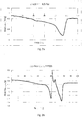
- Figures 3a-3d illustrate graphs showing the heat flow to the sample over the scanned temperature ranges for LEP printing compositions comprising Electroink 4.5 paste (25wt% first resin component, the first resin component being 20wt% A-C® 5120 and 80wt% Nucrel® 699, and 75wt% Isopar L as a carrier liquid) as the first resin component and a second resin component.
- Figure 3a illustrates a graph showing the heat flow to a sample of a LEP printing composition containing 61.6g of Electroink 4.5 paste and 24g Reafree® UV 2335 as the second resin component.
- Figure 3b illustrates a graph showing the heat flow to a sample of a LEP printing composition containing 61.6g of Electroink 4.5 paste and 24 g Dynacoll® 7360 as the second resin component.
- Figure 3c illustrates a graph showing the heat flow to a sample of a LEP printing composition containing 61.6g of Electroink 4.5 paste and 24g Fusabond® C190 as the second resin component.
- Figure 3d illustrates a graph showing the heat flow to a sample of a LEP printing composition containing 77.6g Electroink 4.5 paste and 20g SMA® 1000p as the second resin component.
- Table 1 below shows the melting point for Electroink 4.5 paste (25wt% first resin component, the first resin component being 20wt% A-C® 5120 and 80wt% Nucrel® 699, and 75wt% Isopar L as a carrier liquid) and each of the second resin components tested alone and as part of a LEP printing composition comprising Electroink 4.5 paste as the first resin component as determined by the TA instruments Discovery model DSC.
- the melting points of each of the second resin components contained in each of the LEP printing compositions were determined from the DSC data, using the melting points of each of the second resin components and the Electroink 4.5 paste shown in the first column of the table to assign melting points to the first or second resin components at heat flow minima in the data collected by DSC for the LEP printing compositions as illustrated in Figures 3a-3d .
- the LEP printing composition of Example 1 was introduced into a LEP printing apparatus, in this example a HP indigo 7000 series printing system was used.
- the LEP printing composition of Example 1 was supplied to a BID in the LEP printing apparatus
- the LEP printing apparatus used in this example also contained four BID units each comprising a coloured toner reservoir, the four coloured toner reservoirs containing cyan, magenta, yellow and black coloured electrostatic inks respectively.
- the coloured electrostatic inks used were all Electroink®4.5 inks (HP Indigo) which comprise a pigment and a first resin component containing 20wt% A-C® 5120 and 80wt% Nucrel® 699.
- An LEP printing apparatus was used to produce a print substrate electrostatically printed with a CMYK coloured image and four layers of the LEP printing composition printed on top of the CMYK coloured image as an adhesive layer.
- the print substrate on which a coloured image overprinted with a LEP printing composition image was then fed to a foiling station at which a foiling material being a gold coloured film (Jolybar TD Plus Gold 4001 305 mm) was placed on the print with the back of a foiling film with the foiling material facing the print substrate.
- the print substrate and the foiling film with the foiling material were passed through a roll laminator (GMP, Korea) at 28 mm/sec. The rolls were heated to 75°C at maximum machine pressure.
- the foil was transferred selectively to the print surface only to the areas of the LEP printing composition image. No foiling material was left on any part of the coloured image that was not overprinted with the LEP printing composition after removal of the foiling film from the print substrate.
- Example 6 The method of Example 6 was repeated, except that the print substrate with a CMYK coloured image overprinted with the LEP printing composition image was fed to a glossing station.
- a smooth polyester metalized film (clear metal PET+PR, Hanita coatings 23 micron thick) for smoothing the melted ink was placed on the print prior to subjecting the print to pressure and heat for glossing.
- the print substrate was passed through using roll laminator (GMP, Korea) at 28 mm/sec. The rolls were heated to 75°C, maximum machine pressure was applied in the laminator.
- the smooth polyester metalized film was peeled off the substrate after cooling to room temperature leaving a glossy area on the selected areas (where the LEP printing composition was printed) on the print substrate.
- Gloss of the substrate was determined at 60° using "micro-Tri- gloss” (BYK Gardner Gmbh, Germany).
- the gloss of the LEP printing composition formed after passing through the glossing station was 55 gloss units (GU) compared the coloured toner image having a gloss of 19 GU, showing that the LEP printing composition of Example 1 can be used as a glossing composition to selectively gloss an area of an image on a print substrate.
- Example 6 The method of Example 6 was repeated, except that the LEP printing composition used was the LEP printing composition of Example 2 and in the foiling station the rolls were heated to 80°C.
- the foiling film was peeled off the print substrate after cooling to room temperature leaving a golden foiling material image on selected areas (only areas where the LEP printing composition was printed) on the printed image. No foiling material was left on any part of the coloured images that were not overprinted with the LEP printing composition after removal of the foiling film from the print substrate.
- the LEP printing composition of Example 2 can be used as an adhesive to adhere a foiling material to selected regions of a print substrate.
- Example 6 The method of Example 6 was repeated, except that the LEP printing composition used was the LEP printing composition of Example 3.
- the print substrate with the gold coloured film for foiling were passed through a roll laminator (GMP, Korea) at 4.5 mm/sec. The rolls were heated to 75°C, maximum machine pressure was applied in the laminator.
- the foiling film was peeled off the print substrate after cooling to room temperature leaving a golden foiling material image on selected areas (only areas where the LEP printing composition was printed) on the print. No foiling material was left on any part of the coloured images that were not overprinted with the LEP printing composition after removal of the foiling film from the print substrate.
- the LEP printing composition of Example 3 can be used as an adhesive to adhere a foiling material to selected regions of a print substrate.
- Example 7 The method of Example 7 was repeated, except that the LEP printing composition used was the LEP printing composition of Example 4.
- the smoothing film was peeled off the print substrate after cooling to room temperature leaving a glossy area on the selected areas (where the LEP printing composition was printed) on the print. Gloss of the substrate was determined at 60° using "micro-Tri-gloss" (BYK Gardner Gmbh, Germany).
- the LEP printing composition image was determined to have a gloss of 35.4 GU compared to the coloured toner image having a gloss of 16.4 GU, showing that the LEP printing composition of Example 4 can be used as a glossing composition to selectively gloss an area of an image on a print substrate.
- Example 7 The method of Example 7 was repeated, except that the LEP printing composition used was the LEP printing composition of Example 5 and only one layer of the LEP printing composition was printed on top of the coloured toner image.
- the smoothing film was peeled off the print substrate after cooling to room temperature leaving a gloss inhibited (i.e. matt) area on the selected areas (where the LEP printing composition was printed) on the print.
- Gloss of the substrate was determined at 60° using "micro-Tri- gloss” (BYK Gardner Gmbh, Germany).
- the LEP printing composition image was determined to have a gloss of 13.4 GU compared to the coloured toner image having a gloss of 25.2 GU, showing that the LEP printing composition of Example 5 can be used as a gloss inhibiting (or matt) LEP printing composition to selectively inhibit the formation of a gloss image on an area of an image on a print substrate or selectively print a matt image.
- Examples 6-11 above illustrate that the LEP printing compositions described herein may be be used as a selective adhesive LEP printing compositions, selective glossing LEP printing compositions or selective gloss inhibiting LEP printing compositions.
Claims (15)
- Flüssige-Elektrophotographische(liquid electro photographic - LEP)-Druckzusammensetzung, die Folgendes umfasst:eine erste Harzkomponente, die ein Ethylen-Acrylsäure-Harz, ein Ethylen-MethacrylsäureHarz oder Kombinationen davon umfasst; undeine zweite Harzkomponente, die in einer Menge von etwa 20 bis etwa 80 Gew.-% des Gesamtfeststoffgehalts der Zusammensetzung vorhanden ist, wobei die zweite Harzkomponente einen Schmelzpunkt von etwa 50 °C bis etwa 75 °C, was unter dem Schmelzpunkt der ersten Harzkomponente liegt, oder von etwa 140 °C bis etwa 180 °C aufweist, was über dem Schmelzpunkt der ersten Harzkomponente liegt.
- LEP-Druckzusammensetzung nach Anspruch 1, wobei die zweite Harzkomponente einen Schmelzpunkt von etwa 50 °C bis etwa 70 °C aufweist.
- LEP-Druckzusammensetzung nach Anspruch 1, wobei die zweite Harzkomponente in einer Menge von wenigstens 40 Gew.-% des Gesamtfeststoffgehalts der Zusammensetzung vorhanden ist.
- LEP-Druckzusammensetzung nach Anspruch 1, die ferner eine Trägerflüssigkeit umfasst und wobei die erste und zweite Harzkomponente in der Trägerflüssigkeit dispergiert sind.
- LEP-Druckzusammensetzung nach Anspruch 4, wobei die zweite Harzkomponente einen Quellungsindex von weniger als 20 % in der Trägerflüssigkeit aufweist.
- LEP-Druckzusammensetzung nach Anspruch 1, wobei die erste Harzkomponente einen Schmelzpunkt von etwa 80 °C bis etwa 120 °C aufweist.
- LEP-Druckzusammensetzung nach Anspruch 1, wobei die erste Harzkomponente einen Schmelzpunkt von etwa 90 °C bis etwa 110 °C aufweist.
- LEP-Druckzusammensetzung nach Anspruch 1, wobei die Zusammensetzung transparent ist.
- LEP-Druckzusammensetzung nach Anspruch 1, wobei die zweite Harzkomponente ein Harz ist, das aus einem Urethanacrylat, einem Copolyester, einem Ethylen-Vinylacetat-Copolymer und einem Styrol-Maleinsäureanhydrid-Copolymer ausgewählt ist.
- LEP-Druckzusammensetzung nach Anspruch 1, wobei die erste Harzkomponente ein Ethylen-Acrylsäureharz und ein Ethylen-Methacrylsäureharz umfasst.
- Verfahren zum Herstellen einer flüssigen elektrophotographischen (LEP) Druckzusammensetzung, das das Kombinieren einer Trägerflüssigkeit, einer ersten Harzkomponente, die ein Ethylen-Acrylsäureharz, ein Ethylen-Methacrylsäureharz oder Kombinationen davon umfasst, und etwa 20 bis etwa 80 Gew.-% eines Gesamtfeststoffgehalts der Zusammensetzung einer zweiten Harzkomponente umfasst, die einen Schmelzpunkt von etwa 50 °C bis etwa 75 °C, was unter dem Schmelzpunkt der ersten Harzkomponente liegt, oder von etwa 140 °C bis etwa 180 °C aufweist, was über dem Schmelzpunkt der ersten Harzkomponente liegt.
- Verfahren zum elektrophotographischen Drucken einer Flüssige-Elektrophotographische(LEP)-Druckzusammensetzung, wobei die Zusammensetzung Folgendes umfasst:eine erste Harzkomponente, die ein Ethylen-Acrylsäure-Harz, ein Ethylen-MethacrylsäureHarz oder Kombinationen davon umfasst;eine zweite Harzkomponente, die in einer Menge von etwa 20 bis etwa 80 Gew.-% des Gesamtfeststoffgehalts der Zusammensetzung vorhanden ist, wobei die zweite Harzkomponente einen Schmelzpunkt von etwa 50 °C bis etwa 75 °C, was unter dem Schmelzpunkt der ersten Harzkomponente liegt, oder von etwa 140 °C bis etwa 180 °C aufweist, was über dem Schmelzpunkt der ersten Harzkomponente liegt; undeine Trägerflüssigkeit, wobei das Verfahren Folgendes umfasst:Ausbilden eines latenten elektrostatischen Bildes auf einer Oberfläche;Inberührungbringen der Oberfläche mit der LEP-Druckzusammensetzung, derart, dass wenigstens ein Teil der LEP-Druckzusammensetzung an der Oberfläche haftet, um ein Bild auf der Oberfläche auszubilden; undÜbertragen des Bildes auf ein Drucksubstrat.
- Verfahren zum elektrophotographischen Drucken nach Anspruch 12, das ferner das Erwärmen des Drucksubstrats umfasst, um eine der ersten Harzkomponente oder der zweiten Harzkomponente der LEP-Druckzusammensetzung wenigstens teilweise zu schmelzen, ohne die andere der ersten Harzkomponente oder der zweiten Harzkomponente zu schmelzen, um ein teilweise geschmolzenes Bild auf dem Drucksubstrat auszubilden.
- Verfahren zum elektrophotographischen Drucken nach Anspruch 13, das ferner das Anwenden von Druck auf das teilweise geschmolzene Bild auf dem Drucksubstrat umfasst, um ein glänzendes Bild auf dem Drucksubstrat auszubilden.
- Verfahren zum elektrophotographischen Drucken nach Anspruch 13, das ferner das Anwenden von Druck und einem Foliermaterial auf das teilweise geschmolzene Bild auf dem Drucksubstrat derart umfasst, dass das Foliermaterial an dem teilweise geschmolzenen Bild anhaftet, um ein Folierbild auf dem Drucksubstrat auszubilden.
Applications Claiming Priority (1)
| Application Number | Priority Date | Filing Date | Title |
|---|---|---|---|
| PCT/EP2015/051018 WO2016116142A1 (en) | 2015-01-20 | 2015-01-20 | Liquid electrophotographic ink composition |
Publications (2)
| Publication Number | Publication Date |
|---|---|
| EP3247754A1 EP3247754A1 (de) | 2017-11-29 |
| EP3247754B1 true EP3247754B1 (de) | 2020-07-29 |
Family
ID=52391967
Family Applications (1)
| Application Number | Title | Priority Date | Filing Date |
|---|---|---|---|
| EP15700721.2A Active EP3247754B1 (de) | 2015-01-20 | 2015-01-20 | Flüssige elektrofotografische tintenzusammensetzung |
Country Status (3)
| Country | Link |
|---|---|
| US (1) | US9857717B2 (de) |
| EP (1) | EP3247754B1 (de) |
| WO (1) | WO2016116142A1 (de) |
Families Citing this family (3)
| Publication number | Priority date | Publication date | Assignee | Title |
|---|---|---|---|---|
| US11067914B2 (en) | 2017-03-17 | 2021-07-20 | Hp Indigo B.V. | Liquid electrophotographic ink(s) |
| EP3589705B1 (de) | 2017-07-10 | 2021-02-24 | HP Indigo B.V. | Flüssige elektrostatische tintenzusammensetzung |
| WO2019203803A1 (en) | 2018-04-17 | 2019-10-24 | Hewlett-Packard Development Company, L.P. | Liquid electrophotographic ink composition |
Family Cites Families (55)
| Publication number | Priority date | Publication date | Assignee | Title |
|---|---|---|---|---|
| US4484970A (en) | 1982-11-01 | 1984-11-27 | Thatcher Plastic Packaging, Inc. | Method of applying decorative foil to materials |
| US5192638A (en) | 1984-12-10 | 1993-03-09 | Spectrum Sciences B.V. | Toner for use in compositions for developing latent electrostatic images, method of making the same, and liquid composition using the improved toner |
| US6146803A (en) | 1991-03-28 | 2000-11-14 | Indigo N.V. | Polymer blend liquid toner compositions |
| US5234783A (en) | 1991-12-16 | 1993-08-10 | Eastman Kodak Company | Method of selectively glossing toner images |
| US5751432A (en) | 1996-05-31 | 1998-05-12 | Xerox Corporation | Highlight gloss for xerographic engine |
| DE69738923D1 (de) | 1997-03-14 | 2008-10-02 | Punch Graphix Int Nv | Verfahren zur Steuerung des Glanzes in einem elektrographischem Gerät |
| US5890032A (en) | 1997-12-17 | 1999-03-30 | Eastman Kodak Company | Belt fusing accessory with selectable fused image gloss |
| US6060204A (en) | 1999-08-30 | 2000-05-09 | Xerox Corporation | Liquid developers and processes thereof |
| AU1822301A (en) | 1999-11-01 | 2001-05-14 | Ronald John Liversage | Printing method |
| CA2391708A1 (en) | 2000-01-09 | 2001-07-19 | Indigo N.V. | Foil printing |
| US6466750B2 (en) | 2000-12-01 | 2002-10-15 | Hewlett-Packard Company | Method and system of fusing portions of a print medium |
| DE10064566A1 (de) | 2000-12-22 | 2002-06-27 | Nexpress Solutions Llc | Verfahren zur Steuerung des Glanzes eines Tonerbildes und digitale Bildaufzeichnungsvorrichtung |
| DE10064552B4 (de) | 2000-12-22 | 2004-10-07 | Nexpress Solutions Llc | Verfahren und Maschine zum Bedrucken und/oder Beschichten eines Substrats |
| US6438336B1 (en) | 2001-02-02 | 2002-08-20 | Hewlett-Packard Company | Method and apparatus for varying gloss level for individual elements printed on a single page |
| US6795681B2 (en) | 2001-10-26 | 2004-09-21 | Konica Corporation | Fixing device controlling method, fixing device, and image forming apparatus for forming fixed images of desired glossiness |
| US20030099007A1 (en) | 2001-11-29 | 2003-05-29 | Towner David K. | Selectable gloss levels and placement |
| US7087305B2 (en) | 2002-05-30 | 2006-08-08 | Eastman Kodak Company | Fuser member with tunable gloss level and methods and apparatus for using the same to fuse toner images |
| US20060127791A1 (en) | 2003-08-13 | 2006-06-15 | Eastman Kodak Company | Creation of different gloss values in print |
| JP4638351B2 (ja) | 2003-12-08 | 2011-02-23 | ヒューレット−パッカード デベロップメント カンパニー エル.ピー. | 選択的な光沢を有する画像の印刷及びそのためのトナー |
| US7139521B2 (en) | 2003-12-23 | 2006-11-21 | Eastman Kodak Company | Gloss and differential gloss control methodology |
| US7877053B2 (en) | 2003-12-23 | 2011-01-25 | Eastman Kodak Company | Adjustable gloss control method with different substrates and 3-D image effect with adjustable gloss |
| JP2005283653A (ja) | 2004-03-26 | 2005-10-13 | Fuji Xerox Co Ltd | 透明トナー及びこれを用いた現像剤、光沢付与装置並びに画像形成装置 |
| US7983581B2 (en) | 2004-04-26 | 2011-07-19 | Canon Kabushiki Kaisha | Fixing method and fixing device with specified temperature relationships for recording medium |
| US7113718B2 (en) | 2004-04-30 | 2006-09-26 | Eastman Kodak Company | Method and apparatus for reducing image artifacts caused by release fluid in an electrophotographic machine |
| JP4306557B2 (ja) | 2004-08-05 | 2009-08-05 | コニカミノルタビジネステクノロジーズ株式会社 | 画像形成システム |
| US7288347B2 (en) | 2004-08-31 | 2007-10-30 | Xerox Corporation | Method of applying spot varnish to xerographic image and emulsion aggregation toners for use therein |
| JP4883914B2 (ja) | 2005-01-24 | 2012-02-22 | 株式会社リコー | 定着装置及びこれを用いる画像形成装置 |
| JP2007086747A (ja) | 2005-08-22 | 2007-04-05 | Canon Inc | 画像形成装置 |
| JP4682036B2 (ja) | 2005-12-16 | 2011-05-11 | キヤノン株式会社 | 画像形成装置及び画像形成方法 |
| CN101473275B (zh) | 2006-05-10 | 2012-02-01 | 惠普发展公司有限责任合伙企业 | 用于液体调色剂的电荷引导剂以及获得包含简单盐的纳米颗粒和磺基琥珀酸盐的材料的方法 |
| US7796145B2 (en) | 2007-04-11 | 2010-09-14 | Hewlett-Packard Development Company, L.P. | Hybrid electro-photographic/ink-jet press print systems and primers |
| JP5273426B2 (ja) | 2007-06-26 | 2013-08-28 | 株式会社リコー | 画像形成装置 |
| US7977023B2 (en) | 2007-07-26 | 2011-07-12 | Hewlett-Packard Development Company, L.P. | Ink formulations and methods of making ink formulations |
| US20100212821A1 (en) | 2007-09-24 | 2010-08-26 | Scodix, Ltd. | System and method for cold foil relief production |
| JP5197056B2 (ja) | 2008-02-15 | 2013-05-15 | キヤノン株式会社 | 画像形成装置、画像形成方法、及びコンピュータプログラム |
| US8440379B2 (en) | 2008-06-10 | 2013-05-14 | Hewlett-Packard Development Company, L.P. | Liquid electrophotographic ink having improved durability |
| US20100071573A1 (en) | 2008-09-24 | 2010-03-25 | Vanpelt Christopher K | Foil transfer apparatus and process |
| JP5293454B2 (ja) | 2009-06-26 | 2013-09-18 | 富士ゼロックス株式会社 | 画像形成装置及び画像形成プログラム |
| JP5434320B2 (ja) | 2009-07-10 | 2014-03-05 | コニカミノルタ株式会社 | 画像形成装置、クリア層形成装置および画像形成システム |
| JP5409187B2 (ja) | 2009-08-17 | 2014-02-05 | キヤノン株式会社 | 画像形成装置及び画像形成方法 |
| JP5506366B2 (ja) | 2009-12-16 | 2014-05-28 | キヤノン株式会社 | 画像形成装置 |
| US8588634B2 (en) | 2010-02-22 | 2013-11-19 | Xerox Corporation | Electrophotographic apparatus |
| CN103347977B (zh) | 2011-01-31 | 2015-04-29 | 惠普发展公司,有限责任合伙企业 | 液体电子照相油墨 |
| EP2691814B1 (de) | 2011-03-30 | 2017-02-08 | Hewlett-Packard Indigo B.V. | Elektrostatische tintenzusammensetzung |
| US9122206B2 (en) | 2011-03-30 | 2015-09-01 | Hewlett-Packard Indigo B.V. | Liquid toner composition |
| JP5787595B2 (ja) | 2011-04-25 | 2015-09-30 | キヤノン株式会社 | 表面処理装置及び画像形成システム |
| JP5794679B2 (ja) | 2011-06-20 | 2015-10-14 | キヤノン株式会社 | 表面処理装置 |
| JP5891669B2 (ja) | 2011-09-15 | 2016-03-23 | 富士ゼロックス株式会社 | 画像形成装置 |
| US8496998B2 (en) | 2011-11-23 | 2013-07-30 | Eastman Kodak Company | Producing gloss watermark on receiver |
| JP6115216B2 (ja) | 2012-04-18 | 2017-04-19 | 株式会社リコー | 印刷制御装置、印刷制御システム、印刷制御方法およびプログラム |
| US9098022B2 (en) | 2012-05-02 | 2015-08-04 | Xerox Corporation | Method and apparatus for generating differential gloss image using laser energy |
| US20140119752A1 (en) | 2012-10-30 | 2014-05-01 | Mark Cameron Zaretsky | Producing raised print using light toner |
| US10983452B2 (en) * | 2012-11-20 | 2021-04-20 | Hp Indigo B.V. | Methods of printing and electrostatic ink compositions |
| WO2014183797A1 (en) | 2013-05-17 | 2014-11-20 | Hewlett-Packard Indigo B.V. | Foil printing |
| WO2014206494A1 (en) * | 2013-06-28 | 2014-12-31 | Hewlett-Packard Indigo B.V. | Colorless digital primer for digital printing |
-
2015
- 2015-01-20 US US15/541,165 patent/US9857717B2/en not_active Expired - Fee Related
- 2015-01-20 WO PCT/EP2015/051018 patent/WO2016116142A1/en active Application Filing
- 2015-01-20 EP EP15700721.2A patent/EP3247754B1/de active Active
Non-Patent Citations (1)
| Title |
|---|
| None * |
Also Published As
| Publication number | Publication date |
|---|---|
| EP3247754A1 (de) | 2017-11-29 |
| US9857717B2 (en) | 2018-01-02 |
| WO2016116142A1 (en) | 2016-07-28 |
| US20170329249A1 (en) | 2017-11-16 |
Similar Documents
| Publication | Publication Date | Title |
|---|---|---|
| US10042308B2 (en) | Electrophotographic printing and foiling | |
| EP3248068B1 (de) | Elektrophotographisches drucken und glanzverfahren | |
| EP3247754B1 (de) | Flüssige elektrofotografische tintenzusammensetzung | |
| EP3240835B1 (de) | Elektrostatische tintenzusammensetzungen | |
| US11207876B2 (en) | Foiling involving electrostatic inks | |
| US10274871B2 (en) | Electrophotographic printing | |
| US10859937B2 (en) | Liquid electrophotographic adhesive composition | |
| EP3873995B1 (de) | Elektrofotografische tintenzusammensetzungen | |
| US20200079106A1 (en) | Foiling involving electrostatic inks | |
| US11442373B2 (en) | Liquid electrostatic ink composition | |
| EP3837324B1 (de) | Elektrofotografische tintenzusammensetzungen | |
| EP3714326B1 (de) | Flüssige elektrofotografische tintenzusammensetzung | |
| US10514635B2 (en) | Liquid electrostatic printing method |
Legal Events
| Date | Code | Title | Description |
|---|---|---|---|
| STAA | Information on the status of an ep patent application or granted ep patent |
Free format text: STATUS: THE INTERNATIONAL PUBLICATION HAS BEEN MADE |
|
| PUAI | Public reference made under article 153(3) epc to a published international application that has entered the european phase |
Free format text: ORIGINAL CODE: 0009012 |
|
| STAA | Information on the status of an ep patent application or granted ep patent |
Free format text: STATUS: REQUEST FOR EXAMINATION WAS MADE |
|
| 17P | Request for examination filed |
Effective date: 20170619 |
|
| AK | Designated contracting states |
Kind code of ref document: A1 Designated state(s): AL AT BE BG CH CY CZ DE DK EE ES FI FR GB GR HR HU IE IS IT LI LT LU LV MC MK MT NL NO PL PT RO RS SE SI SK SM TR |
|
| AX | Request for extension of the european patent |
Extension state: BA ME |
|
| RAP1 | Party data changed (applicant data changed or rights of an application transferred) |
Owner name: HP INDIGO B.V. |
|
| DAX | Request for extension of the european patent (deleted) | ||
| GRAP | Despatch of communication of intention to grant a patent |
Free format text: ORIGINAL CODE: EPIDOSNIGR1 |
|
| STAA | Information on the status of an ep patent application or granted ep patent |
Free format text: STATUS: GRANT OF PATENT IS INTENDED |
|
| INTG | Intention to grant announced |
Effective date: 20200415 |
|
| GRAS | Grant fee paid |
Free format text: ORIGINAL CODE: EPIDOSNIGR3 |
|
| GRAA | (expected) grant |
Free format text: ORIGINAL CODE: 0009210 |
|
| STAA | Information on the status of an ep patent application or granted ep patent |
Free format text: STATUS: THE PATENT HAS BEEN GRANTED |
|
| AK | Designated contracting states |
Kind code of ref document: B1 Designated state(s): AL AT BE BG CH CY CZ DE DK EE ES FI FR GB GR HR HU IE IS IT LI LT LU LV MC MK MT NL NO PL PT RO RS SE SI SK SM TR |
|
| REG | Reference to a national code |
Ref country code: CH Ref legal event code: EP |
|
| REG | Reference to a national code |
Ref country code: AT Ref legal event code: REF Ref document number: 1295764 Country of ref document: AT Kind code of ref document: T Effective date: 20200815 |
|
| REG | Reference to a national code |
Ref country code: IE Ref legal event code: FG4D |
|
| REG | Reference to a national code |
Ref country code: DE Ref legal event code: R096 Ref document number: 602015056452 Country of ref document: DE |
|
| REG | Reference to a national code |
Ref country code: LT Ref legal event code: MG4D |
|
| REG | Reference to a national code |
Ref country code: NL Ref legal event code: MP Effective date: 20200729 |
|
| REG | Reference to a national code |
Ref country code: AT Ref legal event code: MK05 Ref document number: 1295764 Country of ref document: AT Kind code of ref document: T Effective date: 20200729 |
|
| PG25 | Lapsed in a contracting state [announced via postgrant information from national office to epo] |
Ref country code: GR Free format text: LAPSE BECAUSE OF FAILURE TO SUBMIT A TRANSLATION OF THE DESCRIPTION OR TO PAY THE FEE WITHIN THE PRESCRIBED TIME-LIMIT Effective date: 20201030 Ref country code: LT Free format text: LAPSE BECAUSE OF FAILURE TO SUBMIT A TRANSLATION OF THE DESCRIPTION OR TO PAY THE FEE WITHIN THE PRESCRIBED TIME-LIMIT Effective date: 20200729 Ref country code: BG Free format text: LAPSE BECAUSE OF FAILURE TO SUBMIT A TRANSLATION OF THE DESCRIPTION OR TO PAY THE FEE WITHIN THE PRESCRIBED TIME-LIMIT Effective date: 20201029 Ref country code: HR Free format text: LAPSE BECAUSE OF FAILURE TO SUBMIT A TRANSLATION OF THE DESCRIPTION OR TO PAY THE FEE WITHIN THE PRESCRIBED TIME-LIMIT Effective date: 20200729 Ref country code: AT Free format text: LAPSE BECAUSE OF FAILURE TO SUBMIT A TRANSLATION OF THE DESCRIPTION OR TO PAY THE FEE WITHIN THE PRESCRIBED TIME-LIMIT Effective date: 20200729 Ref country code: NO Free format text: LAPSE BECAUSE OF FAILURE TO SUBMIT A TRANSLATION OF THE DESCRIPTION OR TO PAY THE FEE WITHIN THE PRESCRIBED TIME-LIMIT Effective date: 20201029 Ref country code: ES Free format text: LAPSE BECAUSE OF FAILURE TO SUBMIT A TRANSLATION OF THE DESCRIPTION OR TO PAY THE FEE WITHIN THE PRESCRIBED TIME-LIMIT Effective date: 20200729 Ref country code: SE Free format text: LAPSE BECAUSE OF FAILURE TO SUBMIT A TRANSLATION OF THE DESCRIPTION OR TO PAY THE FEE WITHIN THE PRESCRIBED TIME-LIMIT Effective date: 20200729 Ref country code: PT Free format text: LAPSE BECAUSE OF FAILURE TO SUBMIT A TRANSLATION OF THE DESCRIPTION OR TO PAY THE FEE WITHIN THE PRESCRIBED TIME-LIMIT Effective date: 20201130 Ref country code: FI Free format text: LAPSE BECAUSE OF FAILURE TO SUBMIT A TRANSLATION OF THE DESCRIPTION OR TO PAY THE FEE WITHIN THE PRESCRIBED TIME-LIMIT Effective date: 20200729 |
|
| PG25 | Lapsed in a contracting state [announced via postgrant information from national office to epo] |
Ref country code: IS Free format text: LAPSE BECAUSE OF FAILURE TO SUBMIT A TRANSLATION OF THE DESCRIPTION OR TO PAY THE FEE WITHIN THE PRESCRIBED TIME-LIMIT Effective date: 20201129 Ref country code: RS Free format text: LAPSE BECAUSE OF FAILURE TO SUBMIT A TRANSLATION OF THE DESCRIPTION OR TO PAY THE FEE WITHIN THE PRESCRIBED TIME-LIMIT Effective date: 20200729 Ref country code: LV Free format text: LAPSE BECAUSE OF FAILURE TO SUBMIT A TRANSLATION OF THE DESCRIPTION OR TO PAY THE FEE WITHIN THE PRESCRIBED TIME-LIMIT Effective date: 20200729 Ref country code: PL Free format text: LAPSE BECAUSE OF FAILURE TO SUBMIT A TRANSLATION OF THE DESCRIPTION OR TO PAY THE FEE WITHIN THE PRESCRIBED TIME-LIMIT Effective date: 20200729 |
|
| PG25 | Lapsed in a contracting state [announced via postgrant information from national office to epo] |
Ref country code: NL Free format text: LAPSE BECAUSE OF FAILURE TO SUBMIT A TRANSLATION OF THE DESCRIPTION OR TO PAY THE FEE WITHIN THE PRESCRIBED TIME-LIMIT Effective date: 20200729 |
|
| PG25 | Lapsed in a contracting state [announced via postgrant information from national office to epo] |
Ref country code: DK Free format text: LAPSE BECAUSE OF FAILURE TO SUBMIT A TRANSLATION OF THE DESCRIPTION OR TO PAY THE FEE WITHIN THE PRESCRIBED TIME-LIMIT Effective date: 20200729 Ref country code: CZ Free format text: LAPSE BECAUSE OF FAILURE TO SUBMIT A TRANSLATION OF THE DESCRIPTION OR TO PAY THE FEE WITHIN THE PRESCRIBED TIME-LIMIT Effective date: 20200729 Ref country code: IT Free format text: LAPSE BECAUSE OF FAILURE TO SUBMIT A TRANSLATION OF THE DESCRIPTION OR TO PAY THE FEE WITHIN THE PRESCRIBED TIME-LIMIT Effective date: 20200729 Ref country code: RO Free format text: LAPSE BECAUSE OF FAILURE TO SUBMIT A TRANSLATION OF THE DESCRIPTION OR TO PAY THE FEE WITHIN THE PRESCRIBED TIME-LIMIT Effective date: 20200729 Ref country code: SM Free format text: LAPSE BECAUSE OF FAILURE TO SUBMIT A TRANSLATION OF THE DESCRIPTION OR TO PAY THE FEE WITHIN THE PRESCRIBED TIME-LIMIT Effective date: 20200729 Ref country code: EE Free format text: LAPSE BECAUSE OF FAILURE TO SUBMIT A TRANSLATION OF THE DESCRIPTION OR TO PAY THE FEE WITHIN THE PRESCRIBED TIME-LIMIT Effective date: 20200729 |
|
| REG | Reference to a national code |
Ref country code: DE Ref legal event code: R097 Ref document number: 602015056452 Country of ref document: DE |
|
| PG25 | Lapsed in a contracting state [announced via postgrant information from national office to epo] |
Ref country code: AL Free format text: LAPSE BECAUSE OF FAILURE TO SUBMIT A TRANSLATION OF THE DESCRIPTION OR TO PAY THE FEE WITHIN THE PRESCRIBED TIME-LIMIT Effective date: 20200729 |
|
| PLBE | No opposition filed within time limit |
Free format text: ORIGINAL CODE: 0009261 |
|
| STAA | Information on the status of an ep patent application or granted ep patent |
Free format text: STATUS: NO OPPOSITION FILED WITHIN TIME LIMIT |
|
| PG25 | Lapsed in a contracting state [announced via postgrant information from national office to epo] |
Ref country code: SK Free format text: LAPSE BECAUSE OF FAILURE TO SUBMIT A TRANSLATION OF THE DESCRIPTION OR TO PAY THE FEE WITHIN THE PRESCRIBED TIME-LIMIT Effective date: 20200729 |
|
| 26N | No opposition filed |
Effective date: 20210430 |
|
| REG | Reference to a national code |
Ref country code: DE Ref legal event code: R119 Ref document number: 602015056452 Country of ref document: DE |
|
| PG25 | Lapsed in a contracting state [announced via postgrant information from national office to epo] |
Ref country code: SI Free format text: LAPSE BECAUSE OF FAILURE TO SUBMIT A TRANSLATION OF THE DESCRIPTION OR TO PAY THE FEE WITHIN THE PRESCRIBED TIME-LIMIT Effective date: 20200729 Ref country code: MC Free format text: LAPSE BECAUSE OF FAILURE TO SUBMIT A TRANSLATION OF THE DESCRIPTION OR TO PAY THE FEE WITHIN THE PRESCRIBED TIME-LIMIT Effective date: 20200729 |
|
| REG | Reference to a national code |
Ref country code: CH Ref legal event code: PL |
|
| GBPC | Gb: european patent ceased through non-payment of renewal fee |
Effective date: 20210120 |
|
| PG25 | Lapsed in a contracting state [announced via postgrant information from national office to epo] |
Ref country code: LU Free format text: LAPSE BECAUSE OF NON-PAYMENT OF DUE FEES Effective date: 20210120 |
|
| REG | Reference to a national code |
Ref country code: BE Ref legal event code: MM Effective date: 20210131 |
|
| PG25 | Lapsed in a contracting state [announced via postgrant information from national office to epo] |
Ref country code: FR Free format text: LAPSE BECAUSE OF NON-PAYMENT OF DUE FEES Effective date: 20210131 |
|
| PG25 | Lapsed in a contracting state [announced via postgrant information from national office to epo] |
Ref country code: GB Free format text: LAPSE BECAUSE OF NON-PAYMENT OF DUE FEES Effective date: 20210120 Ref country code: LI Free format text: LAPSE BECAUSE OF NON-PAYMENT OF DUE FEES Effective date: 20210131 Ref country code: DE Free format text: LAPSE BECAUSE OF NON-PAYMENT OF DUE FEES Effective date: 20210803 Ref country code: CH Free format text: LAPSE BECAUSE OF NON-PAYMENT OF DUE FEES Effective date: 20210131 |
|
| PG25 | Lapsed in a contracting state [announced via postgrant information from national office to epo] |
Ref country code: IE Free format text: LAPSE BECAUSE OF NON-PAYMENT OF DUE FEES Effective date: 20210120 |
|
| PG25 | Lapsed in a contracting state [announced via postgrant information from national office to epo] |
Ref country code: IS Free format text: LAPSE BECAUSE OF FAILURE TO SUBMIT A TRANSLATION OF THE DESCRIPTION OR TO PAY THE FEE WITHIN THE PRESCRIBED TIME-LIMIT Effective date: 20201129 |
|
| PG25 | Lapsed in a contracting state [announced via postgrant information from national office to epo] |
Ref country code: BE Free format text: LAPSE BECAUSE OF NON-PAYMENT OF DUE FEES Effective date: 20210131 |
|
| PG25 | Lapsed in a contracting state [announced via postgrant information from national office to epo] |
Ref country code: HU Free format text: LAPSE BECAUSE OF FAILURE TO SUBMIT A TRANSLATION OF THE DESCRIPTION OR TO PAY THE FEE WITHIN THE PRESCRIBED TIME-LIMIT; INVALID AB INITIO Effective date: 20150120 |
|
| PG25 | Lapsed in a contracting state [announced via postgrant information from national office to epo] |
Ref country code: CY Free format text: LAPSE BECAUSE OF FAILURE TO SUBMIT A TRANSLATION OF THE DESCRIPTION OR TO PAY THE FEE WITHIN THE PRESCRIBED TIME-LIMIT Effective date: 20200729 |