EP3246277B1 - Abstapelvorrichtung für schalen - Google Patents
Abstapelvorrichtung für schalen Download PDFInfo
- Publication number
- EP3246277B1 EP3246277B1 EP16170142.0A EP16170142A EP3246277B1 EP 3246277 B1 EP3246277 B1 EP 3246277B1 EP 16170142 A EP16170142 A EP 16170142A EP 3246277 B1 EP3246277 B1 EP 3246277B1
- Authority
- EP
- European Patent Office
- Prior art keywords
- tray
- screws
- destacking
- flange
- shell
- Prior art date
- Legal status (The legal status is an assumption and is not a legal conclusion. Google has not performed a legal analysis and makes no representation as to the accuracy of the status listed.)
- Active
Links
Images



Classifications
-
- B—PERFORMING OPERATIONS; TRANSPORTING
- B65—CONVEYING; PACKING; STORING; HANDLING THIN OR FILAMENTARY MATERIAL
- B65G—TRANSPORT OR STORAGE DEVICES, e.g. CONVEYORS FOR LOADING OR TIPPING, SHOP CONVEYOR SYSTEMS OR PNEUMATIC TUBE CONVEYORS
- B65G59/00—De-stacking of articles
- B65G59/06—De-stacking from the bottom of the stack
- B65G59/061—De-stacking from the bottom of the stack articles being separated substantially along the axis of the stack
- B65G59/066—De-stacking from the bottom of the stack articles being separated substantially along the axis of the stack by means of rotary devices or endless elements
-
- B—PERFORMING OPERATIONS; TRANSPORTING
- B65—CONVEYING; PACKING; STORING; HANDLING THIN OR FILAMENTARY MATERIAL
- B65G—TRANSPORT OR STORAGE DEVICES, e.g. CONVEYORS FOR LOADING OR TIPPING, SHOP CONVEYOR SYSTEMS OR PNEUMATIC TUBE CONVEYORS
- B65G59/00—De-stacking of articles
- B65G59/10—De-stacking nested articles
- B65G59/107—De-stacking nested articles by means of rotary devices or endless elements
- B65G59/108—De-stacking nested articles by means of rotary devices or endless elements the axis of rotation being substantially parallel to the axis of the stack
-
- B—PERFORMING OPERATIONS; TRANSPORTING
- B65—CONVEYING; PACKING; STORING; HANDLING THIN OR FILAMENTARY MATERIAL
- B65G—TRANSPORT OR STORAGE DEVICES, e.g. CONVEYORS FOR LOADING OR TIPPING, SHOP CONVEYOR SYSTEMS OR PNEUMATIC TUBE CONVEYORS
- B65G35/00—Mechanical conveyors not otherwise provided for
- B65G35/04—Mechanical conveyors not otherwise provided for comprising a flexible load carrier, e.g. a belt, which is wound up at one end and paid out at the other
-
- B—PERFORMING OPERATIONS; TRANSPORTING
- B65—CONVEYING; PACKING; STORING; HANDLING THIN OR FILAMENTARY MATERIAL
- B65G—TRANSPORT OR STORAGE DEVICES, e.g. CONVEYORS FOR LOADING OR TIPPING, SHOP CONVEYOR SYSTEMS OR PNEUMATIC TUBE CONVEYORS
- B65G59/00—De-stacking of articles
- B65G59/10—De-stacking nested articles
- B65G59/107—De-stacking nested articles by means of rotary devices or endless elements
-
- B—PERFORMING OPERATIONS; TRANSPORTING
- B65—CONVEYING; PACKING; STORING; HANDLING THIN OR FILAMENTARY MATERIAL
- B65G—TRANSPORT OR STORAGE DEVICES, e.g. CONVEYORS FOR LOADING OR TIPPING, SHOP CONVEYOR SYSTEMS OR PNEUMATIC TUBE CONVEYORS
- B65G59/00—De-stacking of articles
- B65G59/06—De-stacking from the bottom of the stack
- B65G59/067—De-stacking from the bottom of the stack articles being separated substantially perpendicularly to the axis of the stack
- B65G59/068—De-stacking from the bottom of the stack articles being separated substantially perpendicularly to the axis of the stack by means of endless elements
-
- B—PERFORMING OPERATIONS; TRANSPORTING
- B65—CONVEYING; PACKING; STORING; HANDLING THIN OR FILAMENTARY MATERIAL
- B65G—TRANSPORT OR STORAGE DEVICES, e.g. CONVEYORS FOR LOADING OR TIPPING, SHOP CONVEYOR SYSTEMS OR PNEUMATIC TUBE CONVEYORS
- B65G59/00—De-stacking of articles
- B65G59/10—De-stacking nested articles
-
- B—PERFORMING OPERATIONS; TRANSPORTING
- B65—CONVEYING; PACKING; STORING; HANDLING THIN OR FILAMENTARY MATERIAL
- B65H—HANDLING THIN OR FILAMENTARY MATERIAL, e.g. SHEETS, WEBS, CABLES
- B65H3/00—Separating articles from piles
- B65H3/08—Separating articles from piles using pneumatic force
- B65H3/0808—Suction grippers
- B65H3/0883—Construction of suction grippers or their holding devices
Definitions
- the invention relates to a stacking device for packaging trays according to claim 1.
- a generic tray stacking device according to the preamble of claim 1 st from the U.S. 4,048,915 known.
- the EP 1685047 A1 discloses a stacking device with four unstacking screws which are each arranged at a corner with respect to the stack of containers. Guide elements are provided on all sides in relation to the sides of the stack of containers.
- the disadvantage of this design is the high construction cost of four driven de-stacker screws, and the arrangement of the four de-stacker screws do not allow handling of small containers or a row of stacks of containers lying close together.
- the object of the invention is to provide a simplified stacking device that is also suitable for small trays.
- the stacking device comprises destacking screws for separating and destacking shells of a stack of dishes, each destacking screw having a helix formed as a helical recess.
- the invention is characterized in that two de-stacker screws, which have the same direction of rotation and the same winding direction, are provided for a common shell stack. This enables handling of a row of several tray stacks arranged next to one another, which are only a short distance apart, since the destacking screws are provided in two opposite rows and each in the middle of the stack of trays to be destacked. This also enables very much smaller trays to be unstacked compared to the stacking device according to the prior art, in which four unstacking screws are provided at each of the four corners of the tray stack.
- the two de-stacker screws are preferably arranged in such a way that the shell can be grasped on two opposite side surfaces and transported downwards.
- the helix of the two unstacking screws has a contact height that is at least substantially (that is, apart from a deviation of max. 5 - 10%) corresponds to a flange height of the shell flange in order to be able to hold and unstack the shells with a particularly secure form-fit.
- the contact height (or synonymously: the vertical contact distance) of the coils is defined as follows.
- Each coil is a helical recess in the outer wall of a de-stacker screw.
- this helical recess has an approximately rectangular cross-section which is delimited by essentially horizontal upper and lower sides, an inside running parallel to the axis of rotation of the destacking screw and an open outside that is also parallel to it.
- the upper side of the helical recess merges at an upper outer edge into the generally cylindrical outer wall of the destacking screw, the lower side correspondingly to a lower outer edge.
- this virtual tangential plane perpendicular to the radius of the destacking screw, has a first point of intersection in the ascending direction of the coil with the lower outer edge of the coil in the descending direction of the coil a second point of intersection with the upper outer edge of the helix.
- the contact height (or synonymously the vertical contact distance) is defined as the distance between these two points of intersection projected onto the axial direction of the de-stacker screw.
- the helix has a constant vertical contact distance (contact height) between an upper side and an underside of the helix, so that the shell is guided at four points.
- a first side of the shell flange rests against an upper surface of the helix of the first unstacker screw and the second side of the shell flange opposite the first side rests against an upper surface of the helix of the second unstacker screw.
- the first side of the shell flange rests against a lower surface of the helix of the first unstacking screw and the second side of the shell flange lying opposite the first side rests against a lower surface of the helix of the second unstacking screw.
- the four guide points which are arranged diagonally in this way, ensure that the tray is guided horizontally when separating or when transporting a single tray downwards.
- the contact height of the helix corresponds to the flange height of the shell in order to be able to perform the positive guidance by means of a form fit.
- the de-stacker screws are configured to guide one side of the shell flange each with a point of contact with the outer edge of the upper side and the underside of its helix, so that during the separation by means of the two de-stacker screws arranged on opposite shell flange sides, a three-dimensional four-point guide leads to the position of the shell is determined by the position of the helix of the two de-stacker screws.
- at least two guide devices are arranged on the two opposite sides of the shell, which are not gripped by the two unstacking screws, the two guide devices being vertically aligned and designed or configured to close an already separated shell leaving the unstacking screws downwards to lead.
- the guide devices preferably protrude vertically downwards by at least 5 mm than the end of the helix of the de-stacker screws, in order to ensure safe guidance only through the guide devices themselves without the de-stacker screws.
- further guide devices can be provided on the shell flange sides of the shell in order to further improve the guidance behavior of the shell during the separation process.
- FIG. 1 shows a stacking device 1 according to the invention which is configured to individually drop prefabricated trays 2 onto a transport unit 3 in order to subsequently feed the tray 2, also referred to as a tray, to a filling station or insertion station of a packaging machine.
- the stacking device 1 has vertical guides 4 in order to receive a stack of trays 11.
- Two de-stacker screws 5 engaging the shells 2 are driven by a common motor 6, preferably by a servo motor.
- the two de-stacker screws 5 are each by means of a gear 8 for each unstacking screw 5 is attached to a common gear shaft 7 and is displaceable along this gear shaft 7 in order to be adaptable to different tray sizes.
- FIG 2 shows a perspective view of the two destacker screws 5a and 5b, which both have the same direction of rotation D, namely clockwise here.
- Each destacker screw 5a, 5b has a helix 12 which is designed as a helical recess.
- the winding direction W of the helix is the same for both unstacking screws 5a, 5b in order to transport the shell 2 downwards.
- the winding direction W is defined by the downward inclination in a clockwise direction of rotation D.
- the shell 2 is received in the helix 12 by the destacking screws 5a, 5b on opposite sides of a shell flange 13 of the shell 2.
- the helix 12 has an upper side 14 and an underside 15, as well as an upper outer edge 16 and a lower outer edge 17 in each case.
- Figure 3 shows a plan view of the unstacker screws 5a, 5b, with the shell 2 of the helix 12 of both unstacker screws 5a, 5b being held between the unstacking screw 5a, shown in the drawing above in dotted lines, and the unstacking screw 5b shown below with a dash-dot line, and is moved into the plane of the drawing by a rotation in the direction of rotation D of the destacking screws 5a, 5b.
- the shell 2 stands with its circumferential shell flange 13 with two points of contact each on the outer edges 16, 17 of the upper side 14 and the lower side 15 of the respective helix 12 of the destacking screws 5a, 5b, as in FIG Figure 2 shown in contact.
- the first shell flange side 13a of the shell 2 which is located at the top, touches the underside 15 of the first unstacking screw 5a on the outer edge 17 at a first contact point 21a, located on the left, and the top 14 of the first unstacking screw 5a on the outer edge 16 on a second, located on the right Contact point 22a.
- the second shell flange side 13b of the shell 2 which is arranged below, touches the underside 15 of the second destacking screw 5b on the outer edge 17 at a first contact point 21b located on the right and the upper side 14 of the second destacking screw 5b on the outer edge 16 on a second, in the drawing left contact point 22b.
- guide devices 23 are provided (see Fig. Fig. 5 ). If the pitch of the helix 12 changes, the shell 2 is guided in a process-safe manner until it leaves the helix 12 at the lower end of the unstacking screws 5a, 5b.
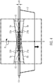
- Figure 4 also shows the flange height 20 of the shell flange 13 and the contact height 10 of both coils 12, the contact height 10 corresponding to the flange height 20 of the shell 2.
- the interaction of the Figures 3 and 4th shows how the contact height (ie the vertical contact spacing) is defined.
- the shell 2 rests with its shell flange section 13a on the inside of the helix 12 of the de-stacker screw 5a.
- a virtual tangential plane is therefore spanned, which on the one hand is parallel to the axis of rotation of the destacking screw 5a and on the other hand contains the outer edge of the shell flange section 13a when the shell flange rests against the inside of the helix 12.
- Figure 5 shows a plan view of the unstacking device 1 with vertically aligned guide devices 23 in the form of round bars on those sides of the shell flange 13 that are not in contact with the unstacking screws (5a, 5b). Further guide devices 24 on the other shell flange sides 13a, 13b are conceivable.
Landscapes
- Engineering & Computer Science (AREA)
- Mechanical Engineering (AREA)
- Sheets, Magazines, And Separation Thereof (AREA)
- Containers Having Bodies Formed In One Piece (AREA)
- Warehouses Or Storage Devices (AREA)
Description
- Die Erfindung bezieht sich auf eine Abstapelvorrichtung für Verpackungs-Schalen gemäß dem Anspruch 1.
- Eine gattungsgemäße Schalenabstapelvorrichtung gemäß dem Oberbegriff des Anspruchs 1 st aus der
US 4,048,915 bekannt. - Die
EP 1685047 A1 offenbart eine Abstapelvorrichtung mit vier Entstaplerschrauben, die jeweils an einer Ecke bezogen auf den Behälterstapel angeordnet sind. Bezogen auf die Seiten des Behälterstapels sind allseitig Führungselemente vorgesehen. Nachteilig an dieser Ausführung ist der konstruktiv hohe Aufwand von vier angetriebenen Entstaplerschrauben, und die Anordnung der vier Entstaplerschrauben erlauben keine Handhabung kleiner Behälter bzw. keine Reihe von nahe beieinander liegenden Behälterstapel. - Aufgabe der Erfindung ist es, eine vereinfachte Abstapelvorrichtung geeignet auch für kleine Schalen bereitzustellen.
- Diese Aufgabe wird gelöst durch eine Abstapelvorrichtung mit den Merkmalen des Anspruchs 1. Vorteilhafte Weiterbildungen der Erfindung sind in den Unteransprüchen angegeben.
- Die erfindungsgemäße Abstapelvorrichtung umfasst Entstaplerschrauben zum Vereinzeln und Abstapeln von Schalen eines Schalenstapels, wobei jede Entstaplerschraube eine als helixförmige Aussparung ausgebildete Wendel aufweist. Die Erfindung zeichnet sich dadurch aus, dass zwei Entstaplerschrauben, die eine gleiche Drehrichtung und eine gleiche Windungsrichtung aufweisen, für einen gemeinsamen Schalenstapel vorgesehen sind. Dies ermöglicht eine Handhabung einer Reihe von mehreren nebeneinander angeordneten Traystapeln, die nur einen geringen Abstand zueinander aufweisen, da die Entstaplerschrauben in zwei gegenüberliegenden Reihen und jeweils mittig zum zu entstapelnden Schalenstapel vorgesehen sind. Dies ermöglicht auch ein Entstapeln von sehr viel kleineren Schalen gegenüber der Abstapelvorrichtung gemäß dem Stand der Technik, bei der jeweils vier Entstaplerschrauben an den vier Ecken des Schalenstapels vorgesehen sind.
- Dabei sind die zwei Entstaplerschrauben vorzugsweise derart angeordnet, dass die Schale an zwei gegenüberliegenden Seitenflächen erfassbar und nach unten transportierbar ist.
- Bei der Erfindung weist die Wendel beider Entstaplerschrauben eine Kontakthöhe auf, die zumindest im Wesentlichen (d.h. bis auf eine Abweichung von max. 5 - 10%) einer Flanschhöhe des Schalenflansches entspricht, um die Schalen besonders sicher formschlüssig halten und entstapeln zu können.
- Die Kontakthöhe (oder synonym: der vertikale Kontaktabstand) der Wendeln ist wie folgt definiert. Jede Wendel ist eine helixförmig verlaufende Aussparung in der Außenwand einer Entstaplerschraube. An jedem Punkt hat diese helixförmige Aussparung einen etwa rechteckigen Querschnitt, der begrenzt ist von im Wesentlichen horizontalen Ober- und Unterseiten, einer parallel zur Drehachse der Entstaplerschraube verlaufenden Innenseite und einer ebenfalls dazu parallelen, offenen Außenseite. Die Oberseite der helixförmigen Aussparung geht an einer oberen Außenkante in die in der Regel zylindrische Außenwand der Entstaplerschraube über, die Unterseite entsprechend an einer unteren Außenkante. Legt man nun eine virtuelle Tangentialebene an die Innenseite der helixförmigen Aussparung der Wendel an, so hat diese virtuelle, senkrecht zum Radius der Entstaplerschraube stehende Tangentialebene in der ansteigenden Richtung der Wendel einen ersten Schnittpunkt mit der unteren Außenkante der Wendel, in der abfallenden Richtung der Wendel einen zweiten Schnittpunkt mit der oberen Außenkante der Wendel. Die Kontakthöhe (oder synonym der vertikale Kontaktabstand) ist definiert als der Abstand dieser beiden Schnittpunkte projiziert auf die Axialrichtung der Entstaplerschraube. In einer besonders vorteilhaften Ausführung weist die Wendel einen konstanten vertikalen Kontaktabstand (Kontakthöhe) zwischen einer Oberseite und einer Unterseite der Wendel auf, sodass die Schale an vier Punkten geführt wird. Dabei liegt eine erste Seite des Schalenflansches an einer oberen Fläche der Wendel der ersten Entstaplerschraube und die gegenüber der ersten Seite liegende zweite Seite des Schalenflansches an einer oberen Fläche der Wendel der zweiten Entstaplerschraube an. Ebenso liegt die erste Seite des Schalenflansches an einer unteren Fläche der Wendel der ersten Entstaplerschraube und die gegenüber der ersten Seite liegende zweite Seite des Schalenflansches an einer unteren Fläche der Wendel der zweiten Entstaplerschraube an. Die so räumlich diagonal angeordneten vier Führungspunkte sorgen für eine horizontale Zwangsführung der Schale beim Vereinzeln bzw. beim Transport einer einzelnen Schale nach unten. Die Kontakthöhe der Wendel entspricht der Flanschhöhe der Schale, um die Zwangsführung mittels Formschluss ausführen zu können.
- Die Entstaplerschrauben sind dazu konfiguriert, jeweils eine Seite des Schalenflansches mit jeweils einem Berührpunkt mit der Außenkante der Oberseite und der Unterseite ihrer Wendel zu führen, so dass bei der Vereinzelung mittels der zwei an gegenüberliegenden Schalenflanschseiten angeordnete Entstaplerschrauben eine räumliche Vierpunkt-Führung dazu führt, dass die Lage der Schale durch die Lage der Wendel der zwei Entstaplerschrauben festlegt ist. Vorzugsweise sind wenigstens zwei Führungsvorrichtungen an den zwei gegenüberliegenden Seiten der Schale angeordnet, die nicht von den zwei Entstaplerschrauben ergriffen werden, wobei die zwei Führungsvorrichtungen vertikal ausgerichtet sind und derart ausgestaltet bzw. dazu konfiguriert sind, eine bereits vereinzelte und die Entstaplerschrauben nach unten verlassende Schale zu führen. Dies führt zu einer exakten Auftreffposition der Schale mit ihrem Schalenboden auf eine unter ihr befindliche Transporteinrichtung, da die Schale auch noch ohne Kontakt mit den Entstaplerschrauben an wenigstens zwei Seiten der Schale geführt ist und die verbleibende Höhe vertikal fallend vollzieht, womit höchstens minimale Abweichungen von der gewünschten Auftreffposition erreicht werden.
- Die Führungsvorrichtungen stehen dabei vorzugsweise um wenigstens 5 mm weiter vertikal nach unten vor als das Ende der Wendel der Entstaplerschrauben, um eine sichere Führung nur durch die Führungsvorrichtungen selbst ohne die Entstaplerschrauben zu gewährleisten.
- Dabei können weitere Führungsvorrichtungen an den Schalenflanschseiten der Schale vorgesehen sein, um das Führungsverhalten der Schale während des Vorganges der Vereinzelung weiter zu verbessern.
- Im Folgenden wird ein vorteilhaftes Ausführungsbeispiel der Erfindung anhand einer Zeichnung näher dargestellt. Im Einzelnen zeigen:
- Fig. 1
- eine schematische Ansicht einer erfindungsgemäßen Abstapelvorrichtung,
- Fig. 2
- eine perspektivische Ansicht der Entstaplerschrauben,
- Fig. 3
- eine Draufsicht auf die Entstaplerschrauben,
- Fig. 4
- eine schematische Schnittansicht A - A und
- Fig. 5
- eine weitere Draufsicht auf die Entstaplerschrauben.
-
Figur 1 zeigt eine erfindungsgemäße Abstapelvorrichtung 1, die dazu konfiguriert ist, um vorgefertigte Schalen 2 einzeln auf eine Transporteinheit 3 fallen zu lassen, um die Schale 2, auch als Tray bezeichnet, anschließend einer Füllstation oder Einlegestation einer Verpackungsmaschine zuzuführen. Die Abstapelvorrichtung 1 weist Vertikalführungen 4 auf, um einen Schalenstapel 11 aufzunehmen. Zwei an den Schalen 2 angreifende Entstaplerschrauben 5 werden von einem gemeinsamen Motor 6, vorzugsweise von einem Servomotor, angetrieben. Die zwei Entstaplerschrauben 5 sind mittels jeweils eines Getriebes 8 für jede Entstaplerschraube 5 auf einer gemeinsamen Getriebewelle 7 angebracht und entlang dieser Getriebewelle 7 verschiebbar, um an unterschiedliche Traygrößen anpassbar zu sein. -
Figur 2 zeigt eine perspektivische Ansicht der zwei Entstaplerschrauben 5a und 5b, die beide die gleiche Drehrichtung D, nämlich hier im Uhrzeigersinn, aufweisen. Jede Entstaplerschraube 5a, 5b weist eine Wendel 12 auf, die als helixförmige Aussparung ausgebildet ist. Die Windungsrichtung W der Wendel ist bei beiden Entstaplerschrauben 5a, 5b gleich, um die Schale 2 nach unten zu transportieren. Die Windungsrichtung W ist definiert durch die Neigung nach unten bei einer Drehrichtung D im Uhrzeigersinn. Die Schale 2 wird von den Entstaplerschrauben 5a, 5b jeweils an gegenüberliegenden Seiten eines Schalenflansches 13 der Schale 2 in der Wendel 12 aufgenommen. Die Wendel 12 weist eine Oberseite 14 und eine Unterseite 15, sowie jeweils eine obere Außenkante 16 und eine untere Außenkante 17 auf. -
Figur 3 zeigt eine Draufsicht auf die Entstaplerschrauben 5a, 5b, wobei zwischen der zeichnerisch oben in gepunkteter Liniendarstellung dargestellten Entstaplerschraube 5a und der zeichnerisch unten mit einer Strich-Punkt-Linie dargestellten Entstaplerschraube 5b die Schale 2 von der Wendel 12 beider Entstaplerschrauben 5a, 5b aufgenommen ist und durch eine Drehung in der Drehrichtung D der Entstaplerschrauben 5a, 5b in die Zeichenebene hinein bewegt wird. Die Schale 2 steht mit ihrem umlaufenden Schalenflansch 13 mit jeweils zwei Berührpunkten an den Außenkanten 16, 17 der Oberseite 14 und der Unterseite 15 der jeweiligen Wendel 12 der Entstaplerschrauben 5a, 5b, wie inFigur 2 gezeigt, in Kontakt. - Die zeichnerisch oben angeordnete erste Schalenflanschseite 13a der Schale 2 berührt die Unterseite 15 der ersten Entstaplerschraube 5a an der Außenkante 17 an einem ersten, zeichnerisch links gelegenen Kontaktpunkt 21a und die Oberseite 14 der ersten Entstaplerschraube 5a an der Außenkante 16 an einem zweiten, zeichnerisch rechts gelegenen Kontaktpunkt 22a. Analog dazu berührt die zeichnerisch unten angeordnete zweite Schalenflanschseite 13b der Schale 2 die Unterseite 15 der zweiten Entstaplerschraube 5b an der Außenkante 17 an einem ersten, zeichnerisch rechts gelegenen Kontaktpunkt 21b und die Oberseite 14 der zweiten Entstaplerschraube 5b an der Außenkante 16 an einem zweiten, zeichnerisch links gelegenen Kontaktpunkt 22b.
- In
Figur 4 werden die vier Kontaktpunkte 21a, 22a, 21b und 22b in einer Ansicht A - A derFigur 3 nochmals dargestellt, wobei die Entstaplerschrauben 5a, 5b jeweils mit nur einem Wendelabschnitt dargestellt sind. Die Wendel 12 der ersten Entstaplerschraube 5a ist in der gepunkteten Liniendarstellung und die Wendel 12 der zweiten Entstaplerschraube 5b mit einer Strich-Punkt-Linie zur besseren Übersichtlichkeit dargestellt. Die inFigur 3 gezeigte Drehung D der Entstaplerschrauben 5a, 5b führt zu einer Bewegung der Schale 2 in Pfeilrichtung nach unten. Dabei wird die Schale 2 an ihrem Flansch 13 jeweils an den Außenkanten 16, 17 der Oberseite 14 und der Unterseite 15 beider Wendeln 12, also an vier Punkten, sicher gehalten und nach unten geführt. Es liegt ein diagonal bzw. über Kreuz gelegener Formschluss vor. - Um eine Verdrehung der Schale 2 weiter zu verhindern, sind Führungsvorrichtungen 23 vorgesehen (s.
Fig. 5 ). Bei einer Steigungsänderung der Wendel 12 ist die Schale 2 bis zum Verlassen der Wendel 12 am unteren Ende der Entstaplerschrauben 5a, 5b prozesssicher geführt. -
Figur 4 zeigt auch die Flanschhöhe 20 des Schalenflansches 13 und die Kontakthöhe 10 beider Wendeln 12, wobei die Kontakthöhe 10 der Flanschhöhe 20 der Schale 2 entspricht. Außerdem wird aus dem Zusammenspiel derFiguren 3 und4 ersichtlich, wie die Kontakthöhe (d.h. der vertikale Kontaktabstand) definiert ist. InFigur 3 liegt die Schale 2 mit ihrem Schalenflanschabschnitt 13a an der Innenseite der Wendel 12 der Entstaplerschraube 5a an. Eine virtuelle Tangentialebene wird demnach aufgespannt, die einerseits parallel zur Drehachse der Entstaplerschraube 5a ist und andererseits die Außenkante des Schalenflanschabschnitts 13a enthält, wenn der Schalenflansch an der Innenseite der Wendel 12 anliegt. - Wie in den
Figuren 3 und4 gezeigt, ergeben sich zwei Schnittpunkte dieser Tangentialebene mit der Wendel 12, nämlich zum Einen ein Schnittpunkt 21a mit der Außenkante des ansteigenden Bereichs der Wendel 12 (d.h. in Drehrichtung D der Entstaplerschraube, ausgehend vom Schnittpunkt der Wendel-Innenseite mit der virtuellen Tangentialebene), zum Anderen ein weiterer Schnittpunkt 22a mit der Außenkante 16 des abfallenden Teils der Wendel (d.h. entgegen der Drehrichtung D der Entstaplerschraube, ausgehend vom Schnittpunkt der Wendel-Innenseite mit der virtuellen Tangentialebene). Der vertikale Abstand zwischen diesen beiden Kontaktpunkten, also projiziert auf die Richtung der Drehachse der Entstaplerschraube 5a (s.Figur 4 ) ist die Kontakthöhe. InFigur 4 ist zu sehen, dass diese im Wesentlichen der Flanschhöhe 20 der Schale 2 entspricht. -
Figur 5 zeigt eine Draufsicht auf die Entstapelvorrichtung 1 mit vertikal ausgerichteten Führungsvorrichtungen 23 in Form von Rundstangen an denjenigen Seiten des Schalenflansches 13, die nicht mit den Entstaplerschrauben (5a, 5b) in Kontakt stehen. Denkbar sind weitere Führungsvorrichtungen 24 an den anderen Schalenflanschseiten 13a, 13b.
Claims (5)
- Schalenabstapelvorrichtung (1), umfassend Entstaplerschrauben (5a, 5b) zum Vereinzeln und Abstapeln von Schalen (2) eines Schalenstapels (11), wobei jede Entstaplerschraube (5a, 5b) eine als helixförmige Aussparung ausgebildete Wendel (12) aufweist, wobei zwei Entstaplerschrauben (5a, 5b), die eine gleiche Drehrichtung (D) und eine gleiche Windungsrichtung (W) aufweisen, einem gemeinsamen Schalenstapel (11) zugeordnet sind,
wobei die Wendel (12) beider Entstaplerschrauben (5a, 5b) eine Kontakthöhe (10) aufweisen, die einer Flanschhöhe (20) des Schalenflansches (13) zumindest im Wesentlichen entspricht,
und wobei die Kontakthöhe (10) der Wendel (12) derart gestaltet ist, dass der Schalenflansch (13) der Schale (2) zwischen jeweils einer Außenkante (16, 17) der Oberseite (14) und der Unterseite (15) der Wendel (12) führbar ist,
dadurch gekennzeichnet, dass die Entstaplerschrauben (5a, 5b) dazu konfiguriert sind, jeweils eine Seite des Schalenflansches (13) mit jeweils einem Berührpunkt (22a, 22b) mit der Außenkante (16, 17) der Oberseite (14) ihrer Wendel (12) und einem weiteren Berührpunkt (21a, 21b) mit der Unterseite (15) ihrer Wendel (12) zu führen. - Schalenabstapelvorrichtung nach Anspruch 1, dadurch gekennzeichnet, dass die zwei Entstaplerschrauben (5a, 5b) derart angeordnet sind, dass die Schale (2) an zwei gegenüberliegenden Seiten (13a, 13) eines Schalenflansches (13) erfassbar und nach unten transportierbar ist.
- Schalenabstapelvorrichtung nach einem der vorangehenden Ansprüche, dadurch gekennzeichnet, dass wenigstens zwei Führungsvorrichtungen (23) an denjenigen zwei gegenüberliegenden Seiten der Schale (2) angeordnet sind, die nicht von den zwei Entstaplerschrauben (5a, 5b) ergriffen werden, wobei die zwei Führungsvorrichtungen (23) vertikal ausgerichtet sind und dazu konfiguriert sind, eine bereits vereinzelte und die Entstaplerschrauben (5a, 5b) nach unten verlassene Schale (2) zu führen.
- Schalenabstapelvorrichtung nach Anspruch 3, dadurch gekennzeichnet, dass die zwei Führungsvorrichtungen (23) um wenigstens 5 mm weiter vertikal nach unten stehen als das untere Ende der Wendel (12) der Entstaplerschrauben (5a, 5b).
- Schalenabstapelvorrichtung nach Anspruch 3 oder 4, dadurch gekennzeichnet, dass weitere Führungsvorrichtungen (24) an den von den Entstaplerschrauben (5a, 5b) erfassten Schalenflanschseiten (13a, 13b) der Schale (2) vorgesehen sind.
Priority Applications (3)
| Application Number | Priority Date | Filing Date | Title |
|---|---|---|---|
| DK16170142.0T DK3246277T3 (da) | 2016-05-18 | 2016-05-18 | Afstablerindretning til bakker |
| EP16170142.0A EP3246277B1 (de) | 2016-05-18 | 2016-05-18 | Abstapelvorrichtung für schalen |
| US15/595,736 US20170334668A1 (en) | 2016-05-18 | 2017-05-15 | Destacker for trays |
Applications Claiming Priority (1)
| Application Number | Priority Date | Filing Date | Title |
|---|---|---|---|
| EP16170142.0A EP3246277B1 (de) | 2016-05-18 | 2016-05-18 | Abstapelvorrichtung für schalen |
Publications (2)
| Publication Number | Publication Date |
|---|---|
| EP3246277A1 EP3246277A1 (de) | 2017-11-22 |
| EP3246277B1 true EP3246277B1 (de) | 2021-01-27 |
Family
ID=56068703
Family Applications (1)
| Application Number | Title | Priority Date | Filing Date |
|---|---|---|---|
| EP16170142.0A Active EP3246277B1 (de) | 2016-05-18 | 2016-05-18 | Abstapelvorrichtung für schalen |
Country Status (3)
| Country | Link |
|---|---|
| US (1) | US20170334668A1 (de) |
| EP (1) | EP3246277B1 (de) |
| DK (1) | DK3246277T3 (de) |
Families Citing this family (11)
| Publication number | Priority date | Publication date | Assignee | Title |
|---|---|---|---|---|
| DE102018100498A1 (de) | 2018-01-11 | 2019-07-11 | Multivac Sepp Haggenmüller Se & Co. Kg | Abstapelvorrichtung für schalen |
| CN108382868A (zh) * | 2018-02-05 | 2018-08-10 | 无锡鼎加弘思饮品科技有限公司 | 自动落杯组件及其落杯工艺方法 |
| DE102018204018A1 (de) | 2018-03-16 | 2019-09-19 | Multivac Sepp Haggenmüller Se & Co. Kg | Verfahren und vorrichtung zum sanften absetzen von schalen |
| CN108792640A (zh) * | 2018-07-26 | 2018-11-13 | 安徽海思达机器人有限公司 | 一种快餐盒取料装置 |
| CN109132577A (zh) * | 2018-08-20 | 2019-01-04 | 南通通机股份有限公司 | 一种新型塑料托盒自动分离系统 |
| CN111837531A (zh) * | 2020-07-30 | 2020-10-30 | 浙江博仁工贸有限公司 | 播种机的叠加育秧盘自动落盘机构 |
| WO2022096581A1 (en) | 2020-11-04 | 2022-05-12 | Js Stål Aps | Destacker unit and system for destacking of objects |
| CN112693682B (zh) * | 2020-12-30 | 2022-05-17 | 浙江翔鹰中央厨房设备有限公司 | 一种自动分盒机 |
| CN112850041A (zh) * | 2021-01-06 | 2021-05-28 | 浙江凯佳塑业有限公司 | 一种基于一次性杯子生产加工用防偏移设备 |
| CN113815952B (zh) * | 2021-10-07 | 2025-05-16 | 东莞市欧尚自动化设备科技有限公司 | 一种高速分盒机 |
| CN119706391A (zh) * | 2024-12-28 | 2025-03-28 | 无锡同联机电工程有限公司 | 一种装盒生产线上的螺旋拆垛装置及拆垛方法 |
Family Cites Families (6)
| Publication number | Priority date | Publication date | Assignee | Title |
|---|---|---|---|---|
| US4048915A (en) * | 1976-04-07 | 1977-09-20 | Condes Corporation | Method and apparatus for denesting cartons |
| NL8005412A (nl) * | 1980-09-30 | 1982-04-16 | Visser S Tech Handelsondernemi | Inrichting voor het een voor een afnemen van voorwerpen uit een stapel. |
| US5788116A (en) * | 1996-05-07 | 1998-08-04 | Fmv Machine Works, Inc. | Adjustable tray dispenser |
| DK1685047T3 (da) | 2003-11-10 | 2009-02-23 | Jysk Konstruktionsteknik As | Dispenseringsapparat der er beregnet til dispensering af stakkede genstande, fremgangmåde til dispensering af stakkede genstande og system omfattende et apparat til dispensering |
| NL1025393C1 (nl) * | 2004-02-03 | 2005-08-08 | Dirk Theo Hiddink | Tray-schaal-of bakjes ontnester, bedoeld voor het verenkelen van stapels. |
| JPWO2009150755A1 (ja) * | 2008-06-13 | 2011-11-10 | 株式会社高井製作所 | 積載パックからのパック取り出し装置及びこの装置を使用した豆腐類のパック詰め方法 |
-
2016
- 2016-05-18 DK DK16170142.0T patent/DK3246277T3/da active
- 2016-05-18 EP EP16170142.0A patent/EP3246277B1/de active Active
-
2017
- 2017-05-15 US US15/595,736 patent/US20170334668A1/en not_active Abandoned
Non-Patent Citations (1)
| Title |
|---|
| None * |
Also Published As
| Publication number | Publication date |
|---|---|
| US20170334668A1 (en) | 2017-11-23 |
| EP3246277A1 (de) | 2017-11-22 |
| DK3246277T3 (da) | 2021-04-19 |
Similar Documents
| Publication | Publication Date | Title |
|---|---|---|
| EP3246277A1 (de) | Abstapelvorrichtung für schalen | |
| EP3363752B1 (de) | Entstapelvorrichtung mit rotierender schalenentlastung | |
| EP2585375B1 (de) | Vorrichtung zum transport von einem mit offenen eierverpackungen gebildeten stapel, sowie eine vereinzelungsvorrichtung für die eierverpackungen und eine stapelvorrichtung für die entleerten eierverpackungen | |
| EP2284115A2 (de) | Greifervorrichtung zum gleichzeitigen Erfassen und/oder Greifen mehrerer Gebinde und/oder Kästen | |
| EP3595827B1 (de) | Zentriervorrichtung | |
| EP3889079B1 (de) | Verfahren und anlage zum bilden von stapeln aus stabförmigen gegenständen | |
| EP3187442A1 (de) | Denester | |
| DE102015116530B4 (de) | Palettiervorrichtung | |
| EP2637808A1 (de) | Fördereinrichtung zum fördern von werkstücken | |
| WO2015121207A1 (de) | Vorrichtung zum lagern von filamentspulen | |
| EP2444323A1 (de) | Faltvorrichtung | |
| EP4601976A1 (de) | Vorrichtung zur förderung und vereinzelung von werkstücken | |
| DE3403550A1 (de) | Transport- und lagergestell | |
| EP3024767A1 (de) | Adapterpalette für stapelvorrichtung | |
| DE3726450C1 (en) | Device for loading saggers with ceramic material or for unloading the ceramic material from the saggers | |
| EP0771748B1 (de) | Vorrichtung zum ausgerichteten Zuführen und Auflockern von Stapeln flacher Gegenstände | |
| EP2684823B1 (de) | Vorrichtung zur Bildung und Weitergabe von Blisterstapeln | |
| DE19711464C2 (de) | Verfahren zum Stapeln von Transportkisten und Transportkistenstapellager | |
| EP0634334A1 (de) | Lagerbehälter mit Führungselementen | |
| DE2210383A1 (de) | Vorrichtung zum kreuzweisen stapeln und entstapeln von stapelgut, insbesondere lattenscharen | |
| WO2015103657A1 (de) | Werkzeugspeichersystem für biegewerkzeuge | |
| EP1440923B1 (de) | Anordnung und Verfahren zum sortierten Abstapeln von in Form und/oder Grösse unterschiedlicher Lagen aus blattförmigen Materialien | |
| DE2211494A1 (de) | Blattzuführvorrichtung | |
| DE102016113573B4 (de) | Vorrichtung zum Stapeln/Entstapeln von Warenträgern | |
| DE1206295B (de) | Vorrichtung zum schrittweisen Foerdern von Stapeln flacher Gegenstaende |
Legal Events
| Date | Code | Title | Description |
|---|---|---|---|
| PUAI | Public reference made under article 153(3) epc to a published international application that has entered the european phase |
Free format text: ORIGINAL CODE: 0009012 |
|
| STAA | Information on the status of an ep patent application or granted ep patent |
Free format text: STATUS: THE APPLICATION HAS BEEN PUBLISHED |
|
| AK | Designated contracting states |
Kind code of ref document: A1 Designated state(s): AL AT BE BG CH CY CZ DE DK EE ES FI FR GB GR HR HU IE IS IT LI LT LU LV MC MK MT NL NO PL PT RO RS SE SI SK SM TR |
|
| AX | Request for extension of the european patent |
Extension state: BA ME |
|
| STAA | Information on the status of an ep patent application or granted ep patent |
Free format text: STATUS: REQUEST FOR EXAMINATION WAS MADE |
|
| 17P | Request for examination filed |
Effective date: 20180315 |
|
| RBV | Designated contracting states (corrected) |
Designated state(s): AL AT BE BG CH CY CZ DE DK EE ES FI FR GB GR HR HU IE IS IT LI LT LU LV MC MK MT NL NO PL PT RO RS SE SI SK SM TR |
|
| GRAP | Despatch of communication of intention to grant a patent |
Free format text: ORIGINAL CODE: EPIDOSNIGR1 |
|
| STAA | Information on the status of an ep patent application or granted ep patent |
Free format text: STATUS: GRANT OF PATENT IS INTENDED |
|
| INTG | Intention to grant announced |
Effective date: 20200902 |
|
| GRAS | Grant fee paid |
Free format text: ORIGINAL CODE: EPIDOSNIGR3 |
|
| GRAA | (expected) grant |
Free format text: ORIGINAL CODE: 0009210 |
|
| STAA | Information on the status of an ep patent application or granted ep patent |
Free format text: STATUS: THE PATENT HAS BEEN GRANTED |
|
| AK | Designated contracting states |
Kind code of ref document: B1 Designated state(s): AL AT BE BG CH CY CZ DE DK EE ES FI FR GB GR HR HU IE IS IT LI LT LU LV MC MK MT NL NO PL PT RO RS SE SI SK SM TR |
|
| REG | Reference to a national code |
Ref country code: GB Ref legal event code: FG4D Free format text: NOT ENGLISH |
|
| REG | Reference to a national code |
Ref country code: CH Ref legal event code: EP |
|
| REG | Reference to a national code |
Ref country code: AT Ref legal event code: REF Ref document number: 1358182 Country of ref document: AT Kind code of ref document: T Effective date: 20210215 |
|
| REG | Reference to a national code |
Ref country code: IE Ref legal event code: FG4D Free format text: LANGUAGE OF EP DOCUMENT: GERMAN |
|
| REG | Reference to a national code |
Ref country code: DE Ref legal event code: R096 Ref document number: 502016012286 Country of ref document: DE |
|
| REG | Reference to a national code |
Ref country code: NL Ref legal event code: FP |
|
| REG | Reference to a national code |
Ref country code: DK Ref legal event code: T3 Effective date: 20210415 |
|
| REG | Reference to a national code |
Ref country code: LT Ref legal event code: MG9D |
|
| PG25 | Lapsed in a contracting state [announced via postgrant information from national office to epo] |
Ref country code: BG Free format text: LAPSE BECAUSE OF FAILURE TO SUBMIT A TRANSLATION OF THE DESCRIPTION OR TO PAY THE FEE WITHIN THE PRESCRIBED TIME-LIMIT Effective date: 20210427 Ref country code: FI Free format text: LAPSE BECAUSE OF FAILURE TO SUBMIT A TRANSLATION OF THE DESCRIPTION OR TO PAY THE FEE WITHIN THE PRESCRIBED TIME-LIMIT Effective date: 20210127 Ref country code: HR Free format text: LAPSE BECAUSE OF FAILURE TO SUBMIT A TRANSLATION OF THE DESCRIPTION OR TO PAY THE FEE WITHIN THE PRESCRIBED TIME-LIMIT Effective date: 20210127 Ref country code: GR Free format text: LAPSE BECAUSE OF FAILURE TO SUBMIT A TRANSLATION OF THE DESCRIPTION OR TO PAY THE FEE WITHIN THE PRESCRIBED TIME-LIMIT Effective date: 20210428 Ref country code: LT Free format text: LAPSE BECAUSE OF FAILURE TO SUBMIT A TRANSLATION OF THE DESCRIPTION OR TO PAY THE FEE WITHIN THE PRESCRIBED TIME-LIMIT Effective date: 20210127 Ref country code: NO Free format text: LAPSE BECAUSE OF FAILURE TO SUBMIT A TRANSLATION OF THE DESCRIPTION OR TO PAY THE FEE WITHIN THE PRESCRIBED TIME-LIMIT Effective date: 20210427 Ref country code: PT Free format text: LAPSE BECAUSE OF FAILURE TO SUBMIT A TRANSLATION OF THE DESCRIPTION OR TO PAY THE FEE WITHIN THE PRESCRIBED TIME-LIMIT Effective date: 20210527 |
|
| PG25 | Lapsed in a contracting state [announced via postgrant information from national office to epo] |
Ref country code: SE Free format text: LAPSE BECAUSE OF FAILURE TO SUBMIT A TRANSLATION OF THE DESCRIPTION OR TO PAY THE FEE WITHIN THE PRESCRIBED TIME-LIMIT Effective date: 20210127 Ref country code: PL Free format text: LAPSE BECAUSE OF FAILURE TO SUBMIT A TRANSLATION OF THE DESCRIPTION OR TO PAY THE FEE WITHIN THE PRESCRIBED TIME-LIMIT Effective date: 20210127 Ref country code: RS Free format text: LAPSE BECAUSE OF FAILURE TO SUBMIT A TRANSLATION OF THE DESCRIPTION OR TO PAY THE FEE WITHIN THE PRESCRIBED TIME-LIMIT Effective date: 20210127 Ref country code: LV Free format text: LAPSE BECAUSE OF FAILURE TO SUBMIT A TRANSLATION OF THE DESCRIPTION OR TO PAY THE FEE WITHIN THE PRESCRIBED TIME-LIMIT Effective date: 20210127 |
|
| PG25 | Lapsed in a contracting state [announced via postgrant information from national office to epo] |
Ref country code: IS Free format text: LAPSE BECAUSE OF FAILURE TO SUBMIT A TRANSLATION OF THE DESCRIPTION OR TO PAY THE FEE WITHIN THE PRESCRIBED TIME-LIMIT Effective date: 20210527 |
|
| REG | Reference to a national code |
Ref country code: DE Ref legal event code: R097 Ref document number: 502016012286 Country of ref document: DE |
|
| PG25 | Lapsed in a contracting state [announced via postgrant information from national office to epo] |
Ref country code: SM Free format text: LAPSE BECAUSE OF FAILURE TO SUBMIT A TRANSLATION OF THE DESCRIPTION OR TO PAY THE FEE WITHIN THE PRESCRIBED TIME-LIMIT Effective date: 20210127 Ref country code: EE Free format text: LAPSE BECAUSE OF FAILURE TO SUBMIT A TRANSLATION OF THE DESCRIPTION OR TO PAY THE FEE WITHIN THE PRESCRIBED TIME-LIMIT Effective date: 20210127 Ref country code: CZ Free format text: LAPSE BECAUSE OF FAILURE TO SUBMIT A TRANSLATION OF THE DESCRIPTION OR TO PAY THE FEE WITHIN THE PRESCRIBED TIME-LIMIT Effective date: 20210127 |
|
| PG25 | Lapsed in a contracting state [announced via postgrant information from national office to epo] |
Ref country code: SK Free format text: LAPSE BECAUSE OF FAILURE TO SUBMIT A TRANSLATION OF THE DESCRIPTION OR TO PAY THE FEE WITHIN THE PRESCRIBED TIME-LIMIT Effective date: 20210127 Ref country code: RO Free format text: LAPSE BECAUSE OF FAILURE TO SUBMIT A TRANSLATION OF THE DESCRIPTION OR TO PAY THE FEE WITHIN THE PRESCRIBED TIME-LIMIT Effective date: 20210127 |
|
| PLBE | No opposition filed within time limit |
Free format text: ORIGINAL CODE: 0009261 |
|
| STAA | Information on the status of an ep patent application or granted ep patent |
Free format text: STATUS: NO OPPOSITION FILED WITHIN TIME LIMIT |
|
| REG | Reference to a national code |
Ref country code: CH Ref legal event code: PL |
|
| 26N | No opposition filed |
Effective date: 20211028 |
|
| PG25 | Lapsed in a contracting state [announced via postgrant information from national office to epo] |
Ref country code: ES Free format text: LAPSE BECAUSE OF FAILURE TO SUBMIT A TRANSLATION OF THE DESCRIPTION OR TO PAY THE FEE WITHIN THE PRESCRIBED TIME-LIMIT Effective date: 20210127 Ref country code: AL Free format text: LAPSE BECAUSE OF FAILURE TO SUBMIT A TRANSLATION OF THE DESCRIPTION OR TO PAY THE FEE WITHIN THE PRESCRIBED TIME-LIMIT Effective date: 20210127 Ref country code: CH Free format text: LAPSE BECAUSE OF NON-PAYMENT OF DUE FEES Effective date: 20210531 Ref country code: MC Free format text: LAPSE BECAUSE OF FAILURE TO SUBMIT A TRANSLATION OF THE DESCRIPTION OR TO PAY THE FEE WITHIN THE PRESCRIBED TIME-LIMIT Effective date: 20210127 Ref country code: LI Free format text: LAPSE BECAUSE OF NON-PAYMENT OF DUE FEES Effective date: 20210531 Ref country code: LU Free format text: LAPSE BECAUSE OF NON-PAYMENT OF DUE FEES Effective date: 20210518 |
|
| REG | Reference to a national code |
Ref country code: BE Ref legal event code: MM Effective date: 20210531 |
|
| PG25 | Lapsed in a contracting state [announced via postgrant information from national office to epo] |
Ref country code: SI Free format text: LAPSE BECAUSE OF FAILURE TO SUBMIT A TRANSLATION OF THE DESCRIPTION OR TO PAY THE FEE WITHIN THE PRESCRIBED TIME-LIMIT Effective date: 20210127 |
|
| PG25 | Lapsed in a contracting state [announced via postgrant information from national office to epo] |
Ref country code: IE Free format text: LAPSE BECAUSE OF NON-PAYMENT OF DUE FEES Effective date: 20210518 |
|
| PG25 | Lapsed in a contracting state [announced via postgrant information from national office to epo] |
Ref country code: IS Free format text: LAPSE BECAUSE OF FAILURE TO SUBMIT A TRANSLATION OF THE DESCRIPTION OR TO PAY THE FEE WITHIN THE PRESCRIBED TIME-LIMIT Effective date: 20210527 |
|
| PG25 | Lapsed in a contracting state [announced via postgrant information from national office to epo] |
Ref country code: BE Free format text: LAPSE BECAUSE OF NON-PAYMENT OF DUE FEES Effective date: 20210531 |
|
| PG25 | Lapsed in a contracting state [announced via postgrant information from national office to epo] |
Ref country code: HU Free format text: LAPSE BECAUSE OF FAILURE TO SUBMIT A TRANSLATION OF THE DESCRIPTION OR TO PAY THE FEE WITHIN THE PRESCRIBED TIME-LIMIT; INVALID AB INITIO Effective date: 20160518 |
|
| PG25 | Lapsed in a contracting state [announced via postgrant information from national office to epo] |
Ref country code: CY Free format text: LAPSE BECAUSE OF FAILURE TO SUBMIT A TRANSLATION OF THE DESCRIPTION OR TO PAY THE FEE WITHIN THE PRESCRIBED TIME-LIMIT Effective date: 20210127 |
|
| P01 | Opt-out of the competence of the unified patent court (upc) registered |
Effective date: 20230801 |
|
| PG25 | Lapsed in a contracting state [announced via postgrant information from national office to epo] |
Ref country code: MK Free format text: LAPSE BECAUSE OF FAILURE TO SUBMIT A TRANSLATION OF THE DESCRIPTION OR TO PAY THE FEE WITHIN THE PRESCRIBED TIME-LIMIT Effective date: 20210127 |
|
| PG25 | Lapsed in a contracting state [announced via postgrant information from national office to epo] |
Ref country code: TR Free format text: LAPSE BECAUSE OF FAILURE TO SUBMIT A TRANSLATION OF THE DESCRIPTION OR TO PAY THE FEE WITHIN THE PRESCRIBED TIME-LIMIT Effective date: 20210127 |
|
| PG25 | Lapsed in a contracting state [announced via postgrant information from national office to epo] |
Ref country code: MT Free format text: LAPSE BECAUSE OF FAILURE TO SUBMIT A TRANSLATION OF THE DESCRIPTION OR TO PAY THE FEE WITHIN THE PRESCRIBED TIME-LIMIT Effective date: 20210127 |
|
| PGFP | Annual fee paid to national office [announced via postgrant information from national office to epo] |
Ref country code: NL Payment date: 20250522 Year of fee payment: 10 |
|
| PGFP | Annual fee paid to national office [announced via postgrant information from national office to epo] |
Ref country code: DE Payment date: 20250519 Year of fee payment: 10 |
|
| PGFP | Annual fee paid to national office [announced via postgrant information from national office to epo] |
Ref country code: GB Payment date: 20250522 Year of fee payment: 10 Ref country code: DK Payment date: 20250521 Year of fee payment: 10 |
|
| PGFP | Annual fee paid to national office [announced via postgrant information from national office to epo] |
Ref country code: IT Payment date: 20250530 Year of fee payment: 10 |
|
| PGFP | Annual fee paid to national office [announced via postgrant information from national office to epo] |
Ref country code: FR Payment date: 20250521 Year of fee payment: 10 |
|
| PGFP | Annual fee paid to national office [announced via postgrant information from national office to epo] |
Ref country code: AT Payment date: 20250519 Year of fee payment: 10 |