EP3245413B1 - Metallisches halteelement zum einleiten eines drehmoments in ein kunststoffgehäuse - Google Patents
Metallisches halteelement zum einleiten eines drehmoments in ein kunststoffgehäuse Download PDFInfo
- Publication number
- EP3245413B1 EP3245413B1 EP15808334.5A EP15808334A EP3245413B1 EP 3245413 B1 EP3245413 B1 EP 3245413B1 EP 15808334 A EP15808334 A EP 15808334A EP 3245413 B1 EP3245413 B1 EP 3245413B1
- Authority
- EP
- European Patent Office
- Prior art keywords
- holding element
- plastic housing
- opening
- plastic
- holding
- Prior art date
- Legal status (The legal status is an assumption and is not a legal conclusion. Google has not performed a legal analysis and makes no representation as to the accuracy of the status listed.)
- Active
Links
Images


Classifications
-
- F—MECHANICAL ENGINEERING; LIGHTING; HEATING; WEAPONS; BLASTING
- F16—ENGINEERING ELEMENTS AND UNITS; GENERAL MEASURES FOR PRODUCING AND MAINTAINING EFFECTIVE FUNCTIONING OF MACHINES OR INSTALLATIONS; THERMAL INSULATION IN GENERAL
- F16B—DEVICES FOR FASTENING OR SECURING CONSTRUCTIONAL ELEMENTS OR MACHINE PARTS TOGETHER, e.g. NAILS, BOLTS, CIRCLIPS, CLAMPS, CLIPS OR WEDGES; JOINTS OR JOINTING
- F16B37/00—Nuts or like thread-engaging members
- F16B37/04—Devices for fastening nuts to surfaces, e.g. sheets, plates
- F16B37/06—Devices for fastening nuts to surfaces, e.g. sheets, plates by means of welding or riveting
- F16B37/062—Devices for fastening nuts to surfaces, e.g. sheets, plates by means of welding or riveting by means of riveting
- F16B37/068—Devices for fastening nuts to surfaces, e.g. sheets, plates by means of welding or riveting by means of riveting by deforming the material of the support, e.g. the sheet or plate
-
- B—PERFORMING OPERATIONS; TRANSPORTING
- B29—WORKING OF PLASTICS; WORKING OF SUBSTANCES IN A PLASTIC STATE IN GENERAL
- B29C—SHAPING OR JOINING OF PLASTICS; SHAPING OF MATERIAL IN A PLASTIC STATE, NOT OTHERWISE PROVIDED FOR; AFTER-TREATMENT OF THE SHAPED PRODUCTS, e.g. REPAIRING
- B29C65/00—Joining or sealing of preformed parts, e.g. welding of plastics materials; Apparatus therefor
- B29C65/56—Joining or sealing of preformed parts, e.g. welding of plastics materials; Apparatus therefor using mechanical means or mechanical connections, e.g. form-fits
- B29C65/562—Joining or sealing of preformed parts, e.g. welding of plastics materials; Apparatus therefor using mechanical means or mechanical connections, e.g. form-fits using extra joining elements, i.e. which are not integral with the parts to be joined
-
- F—MECHANICAL ENGINEERING; LIGHTING; HEATING; WEAPONS; BLASTING
- F16—ENGINEERING ELEMENTS AND UNITS; GENERAL MEASURES FOR PRODUCING AND MAINTAINING EFFECTIVE FUNCTIONING OF MACHINES OR INSTALLATIONS; THERMAL INSULATION IN GENERAL
- F16B—DEVICES FOR FASTENING OR SECURING CONSTRUCTIONAL ELEMENTS OR MACHINE PARTS TOGETHER, e.g. NAILS, BOLTS, CIRCLIPS, CLAMPS, CLIPS OR WEDGES; JOINTS OR JOINTING
- F16B37/00—Nuts or like thread-engaging members
- F16B37/12—Nuts or like thread-engaging members with thread-engaging surfaces formed by inserted coil-springs, discs, or the like; Independent pieces of wound wire used as nuts; Threaded inserts for holes
- F16B37/122—Threaded inserts, e.g. "rampa bolts"
-
- B—PERFORMING OPERATIONS; TRANSPORTING
- B29—WORKING OF PLASTICS; WORKING OF SUBSTANCES IN A PLASTIC STATE IN GENERAL
- B29C—SHAPING OR JOINING OF PLASTICS; SHAPING OF MATERIAL IN A PLASTIC STATE, NOT OTHERWISE PROVIDED FOR; AFTER-TREATMENT OF THE SHAPED PRODUCTS, e.g. REPAIRING
- B29C65/00—Joining or sealing of preformed parts, e.g. welding of plastics materials; Apparatus therefor
- B29C65/56—Joining or sealing of preformed parts, e.g. welding of plastics materials; Apparatus therefor using mechanical means or mechanical connections, e.g. form-fits
- B29C65/64—Joining a non-plastics element to a plastics element, e.g. by force
-
- B—PERFORMING OPERATIONS; TRANSPORTING
- B29—WORKING OF PLASTICS; WORKING OF SUBSTANCES IN A PLASTIC STATE IN GENERAL
- B29C—SHAPING OR JOINING OF PLASTICS; SHAPING OF MATERIAL IN A PLASTIC STATE, NOT OTHERWISE PROVIDED FOR; AFTER-TREATMENT OF THE SHAPED PRODUCTS, e.g. REPAIRING
- B29C66/00—General aspects of processes or apparatus for joining preformed parts
- B29C66/01—General aspects dealing with the joint area or with the area to be joined
- B29C66/05—Particular design of joint configurations
- B29C66/20—Particular design of joint configurations particular design of the joint lines, e.g. of the weld lines
- B29C66/21—Particular design of joint configurations particular design of the joint lines, e.g. of the weld lines said joint lines being formed by a single dot or dash or by several dots or dashes, i.e. spot joining or spot welding
-
- B—PERFORMING OPERATIONS; TRANSPORTING
- B29—WORKING OF PLASTICS; WORKING OF SUBSTANCES IN A PLASTIC STATE IN GENERAL
- B29C—SHAPING OR JOINING OF PLASTICS; SHAPING OF MATERIAL IN A PLASTIC STATE, NOT OTHERWISE PROVIDED FOR; AFTER-TREATMENT OF THE SHAPED PRODUCTS, e.g. REPAIRING
- B29C66/00—General aspects of processes or apparatus for joining preformed parts
- B29C66/50—General aspects of joining tubular articles; General aspects of joining long products, i.e. bars or profiled elements; General aspects of joining single elements to tubular articles, hollow articles or bars; General aspects of joining several hollow-preforms to form hollow or tubular articles
- B29C66/51—Joining tubular articles, profiled elements or bars; Joining single elements to tubular articles, hollow articles or bars; Joining several hollow-preforms to form hollow or tubular articles
- B29C66/54—Joining several hollow-preforms, e.g. half-shells, to form hollow articles, e.g. for making balls, containers; Joining several hollow-preforms, e.g. half-cylinders, to form tubular articles
- B29C66/541—Joining several hollow-preforms, e.g. half-shells, to form hollow articles, e.g. for making balls, containers; Joining several hollow-preforms, e.g. half-cylinders, to form tubular articles a substantially flat extra element being placed between and clamped by the joined hollow-preforms
- B29C66/5414—Joining several hollow-preforms, e.g. half-shells, to form hollow articles, e.g. for making balls, containers; Joining several hollow-preforms, e.g. half-cylinders, to form tubular articles a substantially flat extra element being placed between and clamped by the joined hollow-preforms said substantially flat extra element being rigid, e.g. a plate
-
- B—PERFORMING OPERATIONS; TRANSPORTING
- B29—WORKING OF PLASTICS; WORKING OF SUBSTANCES IN A PLASTIC STATE IN GENERAL
- B29C—SHAPING OR JOINING OF PLASTICS; SHAPING OF MATERIAL IN A PLASTIC STATE, NOT OTHERWISE PROVIDED FOR; AFTER-TREATMENT OF THE SHAPED PRODUCTS, e.g. REPAIRING
- B29C66/00—General aspects of processes or apparatus for joining preformed parts
- B29C66/70—General aspects of processes or apparatus for joining preformed parts characterised by the composition, physical properties or the structure of the material of the parts to be joined; Joining with non-plastics material
- B29C66/74—Joining plastics material to non-plastics material
- B29C66/742—Joining plastics material to non-plastics material to metals or their alloys
-
- B—PERFORMING OPERATIONS; TRANSPORTING
- B29—WORKING OF PLASTICS; WORKING OF SUBSTANCES IN A PLASTIC STATE IN GENERAL
- B29L—INDEXING SCHEME ASSOCIATED WITH SUBCLASS B29C, RELATING TO PARTICULAR ARTICLES
- B29L2031/00—Other particular articles
- B29L2031/34—Electrical apparatus, e.g. sparking plugs or parts thereof
- B29L2031/3481—Housings or casings incorporating or embedding electric or electronic elements
Definitions
- the invention relates to a metallic holding element for pressing into an opening of a plastic housing and receiving or introducing a torque in the plastic housing and a corresponding plastic housing.
- Metallic retaining elements in plastic housings serve to absorb or transmit forces, for example also torques, when the plastic housing is fastened to a carrier or a cover on this plastic housing.
- such holding elements should enable adequate anchoring in the surrounding plastic housing without the risk of weakening or even destroying the surrounding plastic housing when the holding element is introduced or the force acting on the holding element.
- the holding elements are to be designed in such a way that as little metallic material as possible and thus ultimately also weight is required, and that these can also be manufactured inexpensively.
- the lateral surface there being provided with a contour which has notches.
- the JP 2011 239600 A describes an electrical junction box for arrangement in a motor vehicle.
- the junction box comprises a plastic housing with a plurality of essentially square openings, into each of which a metallic connection nut for receiving or introducing a torque is pressed.
- the metallic connection nut has a corresponding square basic shape with four main corners connected to one another via straight edges.
- On the wall of the plastic housing that surrounds the respective opening in its axial extent a plurality of press-fit ribs designed as projections are arranged, which extend in the axial direction along the opening to a bottom surface of the opening, the respective connection nut being pressed into the opening by means of the press-fit ribs is.
- a metallic insert can be seen in which the insert is not supposed to absorb any torques, but rather enables tolerance compensation between a plurality of holes correspondingly arranged on a line with an elongated hole shape.
- the cross section of the hole in the plastic is adapted accordingly to the cross section of the insert.
- the production of the plastic housing is simplified if the holding element does not have to be overmolded with the material of the plastic housing as an insert, but can simply be pressed into an opening afterwards.
- holding elements with a cylindrical holding area are known for this.
- such a holding element then has to be pressed into a corresponding opening in the plastic housing with a greater oversize, which in turn increases the required edge in the plastic housing around the opening.
- the object of the present invention is to present a particularly suitable holding element.
- the holding element in the holding area 3 has main corners which are connected to one another via convex edges and there just does not have any concave incisions or notches or even undercuts.
- Such a shape can preferably be produced from a lead-free, metallic material and by cold impact massive forming.
- the main corners each grip a part of the plastic material in the edge area around the holding element, but the edge areas, which are set back compared to a theoretical circle diameter, enable a corresponding plastic edge, and when such a holding element is pressed in, in particular, a part of the plastic material is displaced from the main corners in this area of the edges.
- the retaining element has exactly 3 main corners, the edges being convexly arched in each case by one or more obtuse-angled intermediate corners.
- the angles between the intermediate corners are larger, i.e. even more obtuse-angled than the 120 degrees of the three main corners and are arranged at a distance from the main corners.
- the holding element can be realized with a smaller corner dimension even with a given diameter of an opening in the interior of the holding element and a given minimum wall thickness.
- Such a holding element can in particular be provided with a cylindrical bore with a predetermined undersize for receiving a self-tapping screw and the relevant torque load is thus created especially when screwing in this screw and forming furrows in the corresponding edge area around the opening in the holding element.
- the opening can already be provided with a finished internal thread and the fastening can be carried out with a conventional screw.
- Another alternative is created in that the retaining element is connected to a pin with an external thread, onto which a motor, for example, can then be screwed.
- the main corners are preferably rounded, the rounded area of the main corner preferably being a maximum of 10% of the length of the edge between the main corners.
- the holding element as a holding element that can be pressed into an opening in a plastic housing, the holding element has an insertion area in the direction of the central axis in the insertion direction with an outer circumference tapering inwardly towards the central axis, whereby such a holding element is self-centering during insertion and certain Can compensate for manufacturing tolerances.
- the holding element can have an edge region in the direction of the central axis with an edge running outward from the central axis, the outer circumference of which is larger than in the holding region.
- This edge enlarges, for example, the holding surface or support surface for a printed circuit board or a housing cover and can also serve as a stop when the holding element is pressed into the plastic housing.
- the plastic housing with a holding element is also claimed as a marketable independent unit.
- a particularly preferred development or simplification results from the fact that the plastic housing has a cylindrical press-in opening before the holding element is pressed in, since such a cylindrical press-in opening is of course very easy to produce, on the other hand, the shape of this holding element enables it to be inserted into such a cylindrical, So press in a press-in opening with a circular cross-section.
- the surface cross-sectional dimension of the retaining element compared to the surface cross-sectional dimension of the press-in opening can be made with a smaller oversize compared to the surface cross-sectional dimension of the press-in opening and results from the fact that the press-in opening in the holding area has a surface cross-sectional dimension after the holding element has been pressed in which is a maximum of 7% larger than the cross-sectional area of the press-in opening before pressing, preferably less than 3.5% larger.
- cross-sectional area of the press-in opening (21) to correspond to between 25 to 60% of the cross-sectional area of the plastic dome (22) before it is pressed in, i.e. a relatively large holding element in relation to the cross-sectional area of the plastic dome can be used without the risk exists that the wall of the plastic dome tears.
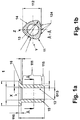
- the Figure 1A shows a first embodiment of the holding element with a longitudinal section along the central axis X.
- the holding element 1 has a holding area 111.
- this holding area 111 is adjoined by an edge area 116 with a circumferential edge 16 on the upper side here.
- this circumferential edge 116 can serve as a stop when the holding element is pressed into a corresponding opening in a plastic housing.
- this edge can be used to provide an enlarged support surface, for example for a printed circuit board 4 or, there, also for fastening the housing part, in Figure 7 to apply the base plate 5 shown there over a correspondingly large area.
- the size and shape of this edge 16 is largely freely selectable and can, for example, also be kept circular and does not have to have main corners 11 of the holding area 111, as will be discussed in more detail below.
- the holding element 1 On the lower side in the direction of the central axis, the holding element 1 has an insertion area (115) with an outer circumference that tapers inwards towards the central axis (X) with the incline (15) that can be seen.
- This insertion area 115 on the press-in side is used for simplified insertion into the press-in opening of the plastic housing.
- the insertion area 115 can be tapered up to a circular outer circumference.
- Figure 1B now shows the in Figure 1A already indicated cross-section through the holding area 111, on which exactly three main corners (11) are executed here, which are connected to one another via edges (12).
- FIG. 1B already outlines a particularly preferred embodiment of these edges 12, namely with 2 obtuse-angled intermediate corners (14) each, so that the overall shape of the edges is slightly outward, that is to say convexly curved. But let it be explicit pointed out that, in principle, other convex edge shapes or, for example, only an obtuse-angled intermediate corner (14) are also conceivable. Due to the disadvantages in terms of manufacturing technology, however, no incisions or even undercuts in the direction of the central axis X are provided in this holding area 111. The special shaping of the edges is also explained in more detail in connection with Figure 6 discussed.
- Figure 2A shows a plan view of what is known as a plastic dome, that is to say a substantially hollow cylindrical body protruding from the plastic housing, which is shown in FIG Figure 7 is shown in cross section.
- This plastic dome 22 has an opening 21 which preferably has a circular shape and a diameter D21 at least in that in the holding area 111 of the holding element of a corresponding area.
- the lower end of the plastic dome 22 can also form the opening for narrow and one additional edge 25, which, however, lies so deep in the insertion direction that the holding element 1 with its holding area 111 can be completely inserted.
- the plastic dome 22 has an outer diameter D22 and the wall thickness of the dome results accordingly as (D22-D21) / 2.
- the inner diameter D 21 of the dome is smaller than that in FIG Figure 1B Sketched corner dimension 112 between the main corner 11 and the respective opposite edge 12, so that there is a press fit of the holding element 1, with plastic material on the edge of the opening 21 not only in the press-in direction, but also in the wall areas of the opening located to the side of the main corners 11 21 is pressed.
- the load on the plastic dome 22 is lower than when a round bolt with a diameter corresponding to the corner dimension 112 is pressed in, but on the other hand this plastic material engaging behind the main corners 11 provides better stability, especially with regard to torque loads.
- the press-in opening 21 has a surface cross-sectional dimension which is a maximum of 7% larger than the surface cross-sectional dimension of the press-in opening 21 before the press-in, preferably is less than 3.5% larger. This makes it possible for the cross-sectional area of the press-in opening 21 to correspond to between 25 to 60% of the cross-sectional area of the plastic dome 2) before the press-in process, i.e. a relatively large holding element in relation to the cross-sectional area of the plastic dome can be used without the risk of the wall of the plastic dome tears.
- FIG Figure 2B now sketches a section through the plastic dome 22 with the pressed-in holding element 1.
- FIG Figure 2C a sketchy view of the opening 21, in which the holding element 1 has been removed again.
- the areas 221 in which the main corners 11 have cut into the wall of the opening 21 as well as the areas 222 in which correspondingly displaced material has additionally built up can be clearly seen, so that the lower edge 25 is even partially covered there can.
- FIG. 5 sketches yet another embodiment not belonging to the invention with now more than 5 main corners, which are arranged in the form of a regular pentagon offset by 72 ° to each other and are again rounded, with the edges 12 opposite the main corners 11 each being straight.
- the main corners 11 each ensure a corresponding incision in the edge area of the opening 21 in the plastic housing and for a corresponding displacement of material into the adjacent wall areas.
- the number of main corners 11 were to be increased further beyond 5, the resulting outer circumferential shape would become increasingly circular and that of the main corners 11 in the tangible wall areas even smaller, so that the decisive inventive effect would only be insufficient and therefore a number of main corners would be larger 5 seems unsuitable.
- the opening 13 is designed, for example, to receive a self-tapping screw 3 or one with an internal thread and is used for screwing into a screw 3, it becomes clear that a corresponding mechanical load is on this wall thickness D123. From the given inside diameter D13 and minimum wall thickness D123, the diameter D33 results. With variant A (not belonging to the invention) this must be significantly larger than with B and C. This means that the plastic dome must also be correspondingly larger.
- the three main corners (11) are connected by edges (12) which each have two obtuse-angled intermediate corners (14) and straight intermediate sections 124, so that the overall shape of the edges 12 are each convexly curved.
- the intermediate corners 14 are preferably arranged here at an identical distance from the main corners 11, and instead of the one shown in FIG Figure 6 the 2 intermediate corners 14 shown, an embodiment with only one intermediate corner or even 3 intermediate corners would also be conceivable, the intermediate corners 14 each being more obtuse than the main corners 11.
- Figure 6C (not belonging to the invention), however, outlines a continuously convex outwardly curved edge 122, which is also opposite the straight edge 121 in FIG Figure 6A allows a greater minimum wall thickness D123c> D123a.
- FIG. 7 now once again outlines a section through the fastening area of a housing of an electronic assembly consisting of a plastic housing part 2 with a plastic dome 22, into which a metallic holding element 1 according to the invention is pressed.
- the housing is closed on the opposite side by a second housing part 5, it being possible for this housing part to be made of metal, for example.
- These two housing parts 2 and 5 are connected to one another by a screw 3 which is screwed into the holding element 1.
- a screw 3 which is screwed into the holding element 1.
- the holding element 1 is free of undercuts in the holding area 111 and has a length in the axial direction X which is shorter than the length of the opening in the plastic dome 22.
- Figure 8 sketches yet another embodiment with a pin (17) connected to the holding element 1 and having an external thread, the fastening area 111 of the holding element 1 again having the cross-sectional shape already explained in more detail above.
- This configuration is also suitable for the holding element (1) to be produced from a lead-free, metallic material and by cold impact massive forming.
Landscapes
- Engineering & Computer Science (AREA)
- General Engineering & Computer Science (AREA)
- Mechanical Engineering (AREA)
- Connection Of Plates (AREA)
- Casings For Electric Apparatus (AREA)
Description
- Die Erfindung betrifft ein metallisches Halteelement zum Einpressen in eine Öffnung eines Kunststoffgehäuses und Aufnehmen bzw. Einleiten eines Drehmoments im Kunststoffgehäuse sowie ein entsprechendes Kunststoffgehäuse.
- Metallische Halteelemente in Kunststoffgehäusen dienen der Aufnahme bzw. Weitergabe von Kräften, beispielsweise auch Drehmomenten bei der Befestigung des Kunststoffgehäuses an einem Träger oder eines Deckels an diesem Kunststoffgehäuse. Generell sollen derartige Halteelemente eine hinreichende Verankerung in dem umgebenden Kunststoffgehäuse ermöglichen, ohne dass dabei die Gefahr besteht, dass umliegende Kunststoffgehäuse beim Einbringen des Halteelements oder der Kraftwirkung auf das Halteelement zu schwächen oder gar zu zerstören. Andererseits sind die Halteelemente so zu konstruieren, dass möglichst wenig metallischer Werkstoff und damit letztlich auch Gewicht benötigt wird und diese zudem kostengünstig hergestellt werden können.
- So ist beispielsweise aus der
DE 10 2012 215 587 A1 ein Lasteinleitungselement zu entnehmen, wobei dort die Mantelfläche mit einer Kontur versehen wird, welche Einkerbungen aufweist. - Aus der
EP 1468199 B1 ist eine Stützhülse sowie derEP 2368051 B1 ein Befestigungsmittel zu entnehmen, welche ebenfalls vergleichbare Formen aufweisen. DieUS 2005/0095078 zeigt zudem einen Blindniet, welcher bereits in seiner Grundform Hinterschnitte aufweist, welche durch beidseitige Kraftwirkung dann noch weiter verformt werden. - Aus der
DE 10 2009 039 817 A1 ist ein selbststanzendes Mutterelement zum Einpressen in ein Metallblechteil zu entnehmen, bei welchem das Mutterelement selbststanzend eine Öffnung in das Metallblech stanzt und das verdrängte Material des Blechs dabei in eine am Mutterelement vorgesehene umlaufende Rille und damit einen Hinterschnitt verformt. Halteelemente mit solchen Einkerbungen sind fertigungstechnisch aufwändig herzustellen und daher teuer und eine derart starke Umformung, wie diese zum Verdrängen des Kunststoffmaterials in derartige Hinterschnitte notwendig wäre, beim Einpressen in Kunststofföffnungen, insbesondere Kunststoffdome mit entsprechend beschränkter Wandstärke nicht möglich bzw. besteht die Gefahr, dass die Wände reißen würden. - Die
JP 2011 239600 A - Außerdem ist aus der
DE 103 19 978 A1 ein metallischer Einsatz zu entnehmen, bei welcher der Einsatz gerade keine Drehmomente aufnehmen soll, sondern mit einer Langlochform einen Toleranzausgleich zwischen einer Mehrzahl entsprechend auf einer Linie angeordneter Bohrungen ermöglicht. Der Querschnitt des Lochs im Kunststoff ist entsprechend an den Querschnitt des Einsatzes angepasst. - Zudem soll möglichst ein bleifreies Material eingesetzt werden können, um die Umweltbelastung zu reduzieren, verlangen einige der vorbekannten Formgebungen nun jedoch eine spanende Verarbeitung und damit einen Bleianteil im Material des Halteelements.
- Außerdem vereinfacht ist die Fertigung des Kunststoffgehäuses, wenn das Halteelement nicht mit dem Material des Kunststoffgehäuses als Einlegeteil umspritzt werden muss, sondern in einer Öffnung nachträglich einfach eingepresst werden kann. Dafür sind beispielsweise Halteelemente mit einem zylinderförmigen Haltebereich bekannt.
- Dann muss jedoch ein solches Halteelement mit einem höheren Übermaß in eine entsprechende Öffnung des Kunststoffgehäuses eingepresst werden, was wiederum den erforderlichen Rand im Kunststoffgehäuse um die Öffnung herum erhöht.
- Insbesondere bei einer Ausbildung eines aus dem Kunststoffgehäuse hervorstehenden Kunststoff-Doms zur Aufnahme des Halteelements ist dies wiederum äußerst unerwünscht, da die Breite eines solchen Kunststoff-Doms die Größe des Kunststoffgehäuses im Vergleich zu einer in den Kunststoffgehäuse anzuordnenden Leiterplatte erhöht. Sofern die Leiterplatte zu dem ebenfalls mit dem Kunststoff-Dom verspannt werden soll, würde die für elektrische Bauelemente verfügbare Leiterplattenfläche ebenfalls reduziert.
- Diese ganzen Anforderungen sind also zueinander im Widerspruch stehend und eine Abwägung entsprechend erforderlich. Die Aufgabe der vorliegenden Erfindung ist es, ein besonders geeignetes Halteelement vorzustellen.
- Diese Aufgabe wird durch die Merkmale der unabhängigen Ansprüche gelöst. Vorteilhafte Weiterbildungen der Erfindung ergeben sich aus den Unteransprüchen, wobei auch Kombinationen und Weiterbildungen einzelner Merkmale miteinander denkbar sind.
- Ein wesentlicher Gedanke der Erfindung besteht darin, dass das Haltelement im Haltebereich 3 Hauptecken aufweist, welche untereinander über konvexe Kanten miteinander verbunden sind und dort gerade keine konkaven Einschnitte oder Einkerbungen oder gar Hinterschnitte aufweist.
- Eine solche Formgebung kann vorzugsweise aus einem bleifreien, metallischen Material und durch Kaltschlagmassivumformung hergestellt werden. Die Hauptecken hintergreifen dabei jeweils einen Teil des Kunststoffmaterials im Randbereich um das Halteelement, ermöglichen die gegenüber einem theoretischen Kreisdurchmesser zurückversetzten Kantenbereiche jedoch einen entsprechenden Kunststoffrand, beim Einpressen eines solchen Halteelements insbesondere auch ein Verdrängen eines Teils des Kunststoffmaterials von den Hauptecken in diesem Bereich der Kanten.
- Um eine Schraubbefestigung zu ermöglichen, weist das Halteelement eine der drei Alternativen auf:
- a) eine zylindrische Bohrung (13) mit einem vorgegebenen Untermaß zur Aufnahme einer selbstschneidenden Schraube (3) oder
- b) ein Innengewinde oder
- c) einen mit dem Halteelement verbundenen Zapfen (17) mit einem Außengewinde.
- Würde man die Anzahl der Hauptecken noch weiter erhöhen, beispielsweise auf 6 Hauptecken oder gar noch mehr ausweichen wollen, wird die Verankerung zunehmend nur noch durch die Haftreibung zwischen Halteelement und dem umgebenden Rand des Kunststoffmaterials erfolgen.
- Das Halteelement weist genau 3 Hauptecken auf, wobei die Kanten jeweils durch eine oder mehrere stumpfwinklige Zwischenecken konvex gewölbt geformt sind.
- Die Zwischenecken sind vom Winkel her größer, also noch stumpfwinkliger als die 120 Grad der drei Hauptecken und beabstandet von den Hauptecken angeordnet. Dadurch kann das Halteelement auch bei einem vorgegebenen Durchmesser einer Öffnung im Inneren des Halteelements und einer vorgegebenen minimalen Wanddicke mit einem kleineren Eckmaß realisiert werden.
- Grundsätzlich wäre auch eine konvexe Kurvenform der Kante denkbar, fertigungstechnisch jedoch aufwändiger.
- Ein solches Haltelement kann insbesondere mit einer zylindrischen Bohrung mit einem vorgegebenen Untermaß zur Aufnahme einer selbstschneidenden Schraube versehen sein und entsteht die maßgebliche Drehmomentbelastung damit insbesondere beim Eindrehen dieser Schraube und der Furchenbildung in dem entsprechenden Randbereich um die Öffnung im Halteelement.
- Alternativ kann die Öffnung auch bereits mit einem fertigen Innengewinde versehen sein und mit einer herkömmlichen Schraube die Befestigung erfolgen. Eine weitere Alternative entsteht, indem das Halteelement mit einem Zapfen mit einem Außengewinde verbunden ist, auf denen dann beispielsweise einem Motor auf geschraubt werden kann.
- Die Hauptecken sind vorzugsweise abgerundet, wobei vorzugsweise der Rundungsbereich der Hauptecke maximal 10% der Länge der Kante zwischen den Hauptecken beträgt.
- Gerade bei einer besonders bevorzugten Weiterbildung als ein in einer Öffnung in ein Kunststoffgehäuse einpressbares Halteelement weist in Richtung der Mittelachse in Einführrichtung das Halteelement einen Einführbereich mit einem sich nach innen zur Mittelachse hin verjüngenden Außenumfang auf, wodurch ein solches Halteelement sich beim Einführen selbst zentrieren und gewisse Fertigungstoleranzen ausgleichen kann.
- Insbesondere auf der entgegengesetzten Seite kann das Halteelement in Richtung der Mittelachse einen Randbereich mit einem von der Mittelachse nach außen verlaufenden Rand aufweist, dessen Außenumfang größer ist als im Haltebereich. Dieser Rand vergrößert beispielsweise die Haltefläche oder Auflagefläche für einer Leiterplatte oder einen Gehäusedeckel und kann zudem als Anschlag beim Einpressen des Halteelements in das Kunststoffgehäuse dienen.
- Neben dem Halteelement als solchen wird als ebenfalls verkehrsfähige eigenständige Einheit das Kunststoffgehäuse mit einem Haltelement nach einem der vorangehenden Ansprüche beansprucht. Eine besonders bevorzugte Weiterbildung bzw. Vereinfachung ergibt sich dadurch, dass das Kunststoffgehäuse einer vor dem Einpressen des Halteelements zylinderförmige Einpressöffnung aufweist, da eine solche zylinderförmigen Einpressöffnung natürlich sehr einfach herstellbar ist, andererseits die Formgebung dieses Halteelements es ermöglicht, es trotzdem in eine solche zylinderförmige, also im Querschnitt kreisrunde Einpressöffnung einzupressen.
- Im Gegensatz zum Einpressen von zylindrischen Metallbolzen in ein Kunststoffgehäuse kann durch ein erfindungsgemäßes Halteelement das Flächenquerschnittsmaß des Halteelements gegenüber dem Flächenquerschnittsmaß der Einpressöffnung vor dem Einpressen mit einem geringeren Übermaß ausgeführt werden und ergibt sich dadurch, dass die Einpressöffnung im Haltebereich nach dem Einpressen des Halteelements ein Flächenquerschnittsmaß aufweist, welches maximal 7% größer ist als das Flächenquerschnittsmaß der Einpressöffnung vor dem Einpressen, vorzugsweise weniger als 3,5% größer ist.
- Dadurch verringert sich die mechanische Belastung des Kunststoffgehäuses um das Halteelement herum und kann bei einem Einpressen in einen aus dem Kunststoffgehäuse hervorstehenden Kunststoff-Dom diese entsprechend mit einem geringen Durchmesser bzw. niedrigerer Wandstärke realisiert werden.
- So wird es möglich, dass das Flächenquerschnittsmaß der Einpressöffnung (21) vor dem Einpressen zwischen 25 bis 60 % des Flächenquerschnittsmaß des Kunststoffdom (22) entspricht, also ein verhältnismäßig großes Halteelement in Bezug auf das Flächenquerschnittsmaß des Kunststoffdoms verwendet werden kann, ohne dass die Gefahr besteht, dass die Wandung des Kunststoffdoms reißt.
- Die Erfindung wird nachfolgend anhand von Ausführungsbeispielen unter Bezugnahme auf die Figuren näher beschrieben. Es zeigen:
- Figur 1
- Schnittansichten durch ein Halteelement gemäß einer 1. Ausgestaltung
- Figur 2a
- Kunststoffgehäuse vor dem Einbau des Halteelements
- Figur 2B
- Kunststoffgehäuse mit eingebautem Halteelement
- Figur 2C
- Kunststoffgehäuse mit entferntem Halteelement
- Figur 3
- Halteelement und Kunststoffgehäuse bei 3 Hauptecken
- Figur 4
- ein nicht zur Erfindung gehörendes Halteelement und Kunststoffgehäuse bei 4 Hauptecken
- Figur 5
- ein nicht zur Erfindung gehörendes Halteelement und Kunststoffgehäuse bei 5 Hauptecken
- Figur 6
- unterschiedliche Kantenformen und dadurch entstehende Maße
- Figur 7
- Schnitt durch den Montagebereich eines Kunststoffgehäuses mit eingebautem Halteelement
- Figur 8
- Halteelement mit angeformtem Bolzen
- Die
Figur 1A zeigt ein 1. Ausführungsbeispiel des Halteelements mit einem Längsschnitt entlang der Mittelachse X. Das Halteelement 1 weist dabei einen Haltebereich 111 auf. An diesen Haltebereich 111 schließt sich in diesem bevorzugten Ausführungsbeispiel auf der hier oberen Seite ein Randbereich 116 mit einem umlaufenden Rand 16 an. - Diese umlaufende Rand 116 kann zum einen als Anschlag dienen, wenn das Halteelement in eine entsprechende Öffnung eines Kunststoffgehäuses eingepresst wird. Andererseits kann dieser Rand dazu dienen, eine vergrößerte Auflagefläche beispielsweise für eine Leiterplatte 4 bzw. ein dort ebenfalls zur Befestigung des Gehäuseteil, in
Figur 7 die dort gezeigte Grundplatte 5 entsprechend großflächig aufzulegen. Die Größe und Form dieses Rands 16 ist dabei weit gehend frei wählbar und kann beispielsweise auch kreisrund gehalten sein und muss nicht wie nachfolgend noch näher zu diskutierenden Hauptecken 11 des Haltebereichs 111 aufweisen. - Auf der in
Figur 1A unteren Seite in Richtung der Mittelachse weist das Halteelement 1 einen Einführbereich (115) mit einem sich nach Innen zur Mittelachse (X) hin mit der erkennbaren Schräge (15) einen verjüngenden Außenumfang auf. Diese Einführbereich 115 an der Einpressseite dient dem vereinfachten Einführen in die Einpressöffnung des Kunststoffgehäuses. Im Gegensatz zu der nachfolgend noch im Detail näher diskutierten Außenumfangform des Halteelements 1 im Haltebereich 111 kann der Einführbereich 115 bis zu einem kreisrunden Außenumfang verjüngt sein. -
Figur 1B zeigt nun den inFigur 1A bereits angedeuteten Querschnitt durch den Haltebereich 111, an welchem hier genau drei Hauptecken (11) ausgeführt sind, welche untereinander über Kanten (12) miteinander verbunden sind. - Die
Figur 1B skizziert bereits eine besonders bevorzugte Ausgestaltung dieser Kanten 12, nämlich mit jeweils 2 stumpfwinkligen Zwischenecken (14), so dass Gesamtform der Kanten leicht nach außen, also konvex gewölbt geformt ist. Es sei aber ausdrücklich darauf hingewiesen, dass grundsätzlich auch andere konvexe Kantenformen oder beispielsweise nur eine stumpfwinklige Zwischenecke (14) denkbar sind. Aufgrund der fertigungstechnischen Nachteile sind in diesem Haltebereich 111 jedoch gerade keine Einschnitte oder gar Hinterschnitte in Richtung der Mittelachse X vorgesehen. Die spezielle Formgebung der Kanten wird auch noch ausführlicher im Zusammenhang mitFigur 6 diskutiert. - Die mögliche alternative Anzahl der Hauptecken 11 wird bezugnehmend auf die
Figuren 3,4 und 5 ebenfalls nachfolgend noch näher diskutiert. - Zunächst aber soll bezugnehmend auf die
Figuren 2A bis 2C eine besonders bevorzugte Ausgestaltung des Kunststoffgehäuses 2 erläutert werden.Figur 2A zeigt dabei eine Draufsicht auf einen so genannten Kunststoffdom, also einen aus dem Kunststoffgehäuse hervorragenden im Wesentlichen hohlzylindrischen Körper, welcher beispielsweise inFigur 7 im Querschnitt gezeigt ist. - Dieser Kunststoffdom 22 weist eine Öffnung 21 auf, welche vorzugsweise eine kreisrunde Form und zumindest in dem im Haltebereich 111 des Halteelements eines entsprechenden Bereichs einen Durchmesser D21 aufweist. Am bezüglich
Figur 7 unteren Ende des Kunststoffdoms 22 kann sich die Öffnung auch für engen und einen zusätzlichen Rand 25 bilden, welcher jedoch in Einführrichtung so tief liegt, dass das Halteelement 1 mit seinem Haltebereich 111 vollständig eingeführt werden kann. - Der Kunststoffdom 22 weist einen Außendurchmesser D22 auf und ergibt sich entsprechend die Wandstärke des Doms als (D22-D21)/2. Der Innendurchmesser D 21 des Doms ist dabei um ein vorgegebenes Maß kleiner als das in
Figur 1B skizzierte Eckmaß 112 zwischen der Hauptecke 11 und der jeweils gegenüberliegenden Kante 12, so dass es zu einer Presspassung des Halteelements 1 kommt, wobei dabei Kunststoffmaterial am Rand der Öffnung 21 nicht nur in Einpressrichtung, sondern auch in die seitlich der Hauptecken 11 befindlichen Wandbereiche der Öffnung 21 verpresst wird. Dadurch ist zum einen die Belastung des Kunststoffdoms 22 geringer als beim Einpressen eines runden Bolzens mit einem dem Eckmaß 112 entsprechenden Durchmesser, andererseits aber durch dieses die Hauptecken 11 hintergreifenden Kunststoffmaterial eine bessere Festlichkeit gerade bezüglich Drehmomentbelastungen gegeben. - Die Einpressöffnung 21 weist im Haltebereich nach dem Einpressen des Halteelements ein Flächenquerschnittsmaß auf, welches maximal 7% größer ist als das Flächenquerschnittsmaß der Einpressöffnung 21 vor dem Einpressen, vorzugsweise weniger als 3,5% größer ist. So wird es möglich, dass das Flächenquerschnittsmaß der Einpressöffnung 21 vor dem Einpressen zwischen 25 bis 60 % des Flächenquerschnittsmaß des Kunststoffdom 2) entspricht, also ein verhältnismäßig großes Halteelement in Bezug auf das Flächenquerschnittsmaß des Kunststoffdoms verwendet werden kann, ohne dass die Gefahr besteht, dass die Wandung des Kunststoffdoms reißt.
-
Figur 2B skizziert nun einen Schnitt durch den Kunststoffdom 22 mit dem eingepressten Halteelement 1. Um die Wirkung des Halteelements 1 beim Einpressen und die Verformung der Öffnung 21 noch besser zu veranschaulichen, wurde inFigur 2C noch skizzenhaft Einblick in die Öffnung 21 dargestellt, bei welcher das Halteelement 1 wieder entfernt wurde. Deutlich zu erkennen sind dabei diejenigen Bereiche 221, in denen sich die Hauptecken 11 in die Wand der Öffnung 21 eingeschnitten haben als auch die Bereiche 222, bei welchem sich entsprechend verdrängtes Material zusätzlich aufgebaut hat, so dass dort der untere Rand 25 sogar teils überdeckt sein kann. - Die
Figur 3 zeigt nun nochmals die bereits in denFiguren 1 und2 beschriebene Ausgestaltung mit 3 Hauptecken sowie den besonders bevorzugten Zwischenecken. - Die
Figur 4 skizziert hingegen eine nicht zur Erfindung gehörende Ausgestaltung mit in diesem Falle 4 Hauptecken, welche zwar ebenfalls abgerundet, ansonsten aber mit geraden Kanten 12 verbunden sind. - Die
Figur 5 skizziert noch eine weitere nicht zur Erfindung gehörende Ausgestaltung mit nun mehr 5 Hauptecken, welche in Form eines regelmäßigen Fünfeckes jeweils um 72° zueinander versetzt angeordnet und wiederum abgerundet sind, wobei auch hier die den Hauptecken 11 jeweils gegenüberliegenden Kanten 12 jeweils gerade ausgeführt sind. - In allen Fällen sorgen die Hauptecken 11 jeweils für einen entsprechenden Einschnitt in den Randbereich der Öffnung 21 im Kunststoffgehäuse und zu einem entsprechenden verdrängen von Material in die benachbarten Wandbereiche. Würde man jedoch die Anzahl der Hauptecken 11 über 5 hinaus weiter erhöhen, wird die entstehende Außenumfangsform zunehmend kreisähnlicher und die von den Hauptecken 11 in der greifbaren Wandbereiche noch kleiner, so dass die maßgebliche erfinderische Wirkung nur noch unzureichend eintritt und daher eine Anzahl von Hauptecken größer 5 ungeeignet erscheint.
- Die
Figuren 6A bis 6C skizzieren nun im Folgenden anhand von Beispielen mit jeweils 3 Hauptecken den besonderen Einfluss der Gestaltung der Kanten für die jeweils kritischen minimalen Dicken des Halteelements einerseits als auch andererseits des Kunststoffgehäuses, insbesondere des Kunststoffdoms. - Gehen wir für alle 3 Beispiele von einem einheitlichen Innendurchmesser D13, sowie einem einheitlichen theoretischen Kreisdurchmesser über die Hauptecken D33 aus, so ergibt sich eine deutlich geringere minimale Wandstärke des Halteelements D123. Um eine ausreichende Festigkeit des Halteelements zu er zielen, darf eine min. Wandstärke nicht unterschritten werden.
- Bedenkt man, dass die Öffnung 13 beispielsweise eine Bohrung zur Aufnahme einer selbstschneidenden Schraube 3 oder einer mit einem Innengewinde ausgestaltet und zum Eindrehen in einer Schraube 3 dient, wird klar, dass eine entsprechende mechanische Belastung auf dieser Wanddicke D123 liegt. Aus gegebenem Innendurchmesser D13 und Mindest-Wandstärke D123 ergibt sich der Durchmesser D33. Dieser muss bei Variante A (nicht zur Erfindung gehörend) deutlich größer ausfallen als bei B und C. Hierdurch muss auch der Kunststoffdom entsprechend größer werden.
- In
Figur 6B sind die drei Hauptecken (11) durch Kanten (12) verbunden, welche jeweils zwei stumpfwinklige Zwischenecken (14) und gerade Zwischenabschnitte 124 aufweisen, so dass die Gesamtform der Kanten 12 jeweils konvex gewölbt geformt sind. Die Zwischenecken 14 sind hier vorzugsweise in jeweils identischen Abstand zu den Hauptecken 11 angeordnet, wobei anstelle der hier inFigur 6 die gezeigten 2 Zwischenecken 14 auch eine Ausgestaltung mit nur einer Zwischenecke oder sogar 3 Zwischenecken denkbar wäre, wobei die Zwischenecken 14 jeweils stumpfwinkliger als die Hauptecken 11 sind. -
Figur 6C (nicht zur Erfindung gehörend) skizziert hingegen eine kontinuierlich konvex nach außen gewölbte Kante 122, welche ebenfalls gegenüber der geraden Kante 121 inFigur 6A eine größere minimale Wanddicke D123c>D123a ermöglicht. -
Figur 7 skizziert nun noch einmal einen Schnitt durch den Befestigungsbereich eines Gehäuses einer elektronischen Baugruppe bestehend aus einem Kunststoffgehäuseteil 2 mit einem Kunststoff-Dom 22, in welchen ein erfindungsgemäßes metallisches Halteelement 1 eingepresst ist. Das Gehäuse wird auf der gegenüberliegenden Seite durch 2. Gehäuseteil 5 verschlossen, wobei dieses Gehäuseteil beispielsweise auch metallisch ausgebildet sein kann. Diese beiden Gehäuseteile 2 und 5 werden durch eine Schraube 3 miteinander verbunden, welche in das Halteelement 1 ein geschraubt ist. Zwischen dem 2. Gehäuseteil 5 und dem 1. Gehäuseteil 2 bzw. dem Rand 16 des Halteelements 1 ist zudem eine Leiterplatte 4 mit elektronischen Bauelementen vorgesehen und ebenfalls dort befestigt. Alternativ zu dieser Ausgestaltung mit einer Schraube 3 wäre auch eine Befestigung mittels Nieten denkbar. Das Halteelement 1 ist im Haltebereich 111 frei von Hinterschnitten und weist in Achsrichtung X eine Länge auf, welche kürzer ist als die Länge der Öffnung im Kunststoffdom 22. -
Figur 8 skizziert hingegen noch eine weitere Ausgestaltung mit einem mit dem Halteelement 1 verbundenen Zapfen (17) mit einem Außengewinde, wobei der Befestigungsbereich 111 des Halteelements 1 wiederum die vorstehend bereits näher erläuterte Querschnittsform aufweist. Auch diese Ausgestaltung eignet sich dafür, dass das Halteelement (1) aus einem bleifreien, metallischen Material und durch Kaltschlagmassivumformung hergestellt ist.
Claims (11)
- Metallisches Haltelement (1) zum Einpressen in eine Öffnung eines Kunststoffgehäuses (2) und Aufnehmen bzw. Einleiten eines Drehmoments im Kunststoffgehäuse (2), wobei
das Haltelement im Haltebereich (111)
frei von konkaven Einschnitten oder Einkerbungen oder Hinterschnitten ist sowie in seiner Querschnittsform drei Hauptecken (11) aufweist, welche untereinander über konvexe Kanten (12) miteinander verbunden sind, wobei die Kanten (12) jeweils durch eine oder mehrere stumpfwinklige Zwischenecken (14) konvex gewölbt geformt sind, wobei
das Halteelement (1) aufweist:a) eine zylindrische Bohrung (13) mit einem vorgegebenen Untermaß zur Aufnahme einer selbstschneidenden Schraube (3) oderb) ein Innengewinde oderc) einen mit dem Halteelement verbundenen Zapfen (17) mit einem Außengewinde. - Metallisches Haltelement nach Anspruch 1, dadurch gekennzeichnet, dass das Halteelement (1) aus einem bleifreien, metallischen Material und durch Kaltschlagmassivumformung hergestellt ist.
- Metallisches Haltelement nach einem der vorangehenden Ansprüche, dadurch gekennzeichnet, dass die Hauptecken (11) abgerundet sind, wobei vorzugsweise der Rundungsbereich der Hauptecke (11) maximal 25% der Länge der Kante (12) zwischen den Hauptecken beträgt.
- Metallisches Haltelement nach einem der vorangehenden Ansprüche, dadurch gekennzeichnet, dass in Richtung der Mittelachse (X) das Halteelement auf einer Seite einen Einführbereich (115) mit einem sich nach innen zur Mittelachse (X) hin verjüngenden (15) Außenumfang aufweist.
- Metallisches Haltelement nach einem der vorangehenden Ansprüche, dadurch gekennzeichnet, dass in Richtung der Mittelachse (X) das Halteelement auf einer Seite einen Randbereich (116) mit einem von der Mittelachse nach außen verlaufenden Rand (16) aufweist, dessen Außenumfang größer ist als im Haltebereich (111).
- Kunststoffgehäuse mit einem Haltelement nach einem der vorangehenden Ansprüche.
- Kunststoffgehäuse nach Anspruch 6 mit einer vor dem Einpressen des Halteelements zylinderförmigen Einpressöffnung und einem in diese Einpressöffnung eingepressten Halteelement nach einem der vorangehenden Ansprüche 1 bis 5.
- Kunststoffgehäuse nach Anspruch 6 oder 7, wobei die Einpressöffnung (21) im Haltebereich nach dem Einpressen des Halteelements ein Flächenquerschnittsmaß aufweist, welches maximal 7% größer ist als das Flächenquerschnittsmaß der Einpressöffnung (21) vor dem Einpressen, vorzugsweise weniger als 3,5% größer ist.
- Kunststoffgehäuse nach einem der Ansprüche 6 bis 8, wobei die Öffnung (21) im Kunststoffgehäuse in einem Kunststoffdom (22) angeordnet ist.
- Kunststoffgehäuse nach Anspruch 9, wobei die Einpressöffnung (21) vor dem Einpressen ein Flächenquerschnittsmaß aufweist, welches zwischen 25 bis 60 % des Flächenquerschnittsmaß des Kunststoffdom (22) entspricht.
- Kunststoffgehäuse nach einem der Ansprüche 6 bis 10, dadurch gekennzeichnet, dass der Haltebereich (111) des metallischen Haltelements in Richtung der Mittelachse (X) eine Länge aufweist, welche kleiner ist als die entsprechende Länge der vorgesehenen Öffnung (21) im Kunststoffgehäuse.
Applications Claiming Priority (2)
| Application Number | Priority Date | Filing Date | Title |
|---|---|---|---|
| DE102015200505.4A DE102015200505A1 (de) | 2015-01-15 | 2015-01-15 | Metallisches Haltelement zum Einleiten eines Drehmoments in ein Kunststoffgehäuse |
| PCT/DE2015/200499 WO2016112886A1 (de) | 2015-01-15 | 2015-11-12 | Metallisches haltelement zum einleiten eines drehmoments in ein kunststoffgehäuse |
Publications (2)
| Publication Number | Publication Date |
|---|---|
| EP3245413A1 EP3245413A1 (de) | 2017-11-22 |
| EP3245413B1 true EP3245413B1 (de) | 2021-07-14 |
Family
ID=54849070
Family Applications (1)
| Application Number | Title | Priority Date | Filing Date |
|---|---|---|---|
| EP15808334.5A Active EP3245413B1 (de) | 2015-01-15 | 2015-11-12 | Metallisches halteelement zum einleiten eines drehmoments in ein kunststoffgehäuse |
Country Status (6)
| Country | Link |
|---|---|
| US (1) | US10323673B2 (de) |
| EP (1) | EP3245413B1 (de) |
| KR (1) | KR102558056B1 (de) |
| CN (1) | CN107110193B (de) |
| DE (2) | DE102015200505A1 (de) |
| WO (1) | WO2016112886A1 (de) |
Families Citing this family (4)
| Publication number | Priority date | Publication date | Assignee | Title |
|---|---|---|---|---|
| DE102013104224A1 (de) * | 2013-04-10 | 2014-10-16 | Heiko Schmidt | Verfahren zum Befestigen eines Fügeelementes in einem Metallblech sowie Fügeelement |
| DE102019203972A1 (de) * | 2019-03-22 | 2020-09-24 | Festo Se & Co. Kg | Kanalgehäuse, fluidtechnisches Gerät und Herstellungsverfahren |
| DE102023002927A1 (de) | 2022-07-28 | 2024-02-08 | Martin Krug | Schraubenmutter zum selbstschneidenden Einschrauben in vorgebohrte Fahrzeug- und Flugzeugteile mit einseitigem Zugang |
| WO2025104463A1 (en) * | 2023-11-16 | 2025-05-22 | Howmet Aerospace Inc. | Nuts, multi-piece fasteners, and methods of manufacture thereof |
Citations (2)
| Publication number | Priority date | Publication date | Assignee | Title |
|---|---|---|---|---|
| JP2000297810A (ja) * | 1999-04-15 | 2000-10-24 | Yazaki Corp | ナットの固定構造 |
| JP2011239600A (ja) * | 2010-05-12 | 2011-11-24 | Sumitomo Wiring Syst Ltd | 電気接続箱 |
Family Cites Families (27)
| Publication number | Priority date | Publication date | Assignee | Title |
|---|---|---|---|---|
| US3304830A (en) * | 1960-08-09 | 1967-02-21 | Goodrich Co B F | Expansible hollow rivet having a polygonal shank |
| US3311148A (en) * | 1965-03-08 | 1967-03-28 | Leitner Kajetan | Conical collar nuts having spaced flats |
| GB2241758B (en) * | 1990-03-07 | 1993-06-30 | Martin George Ollis | Blind hole anchor nut assembly |
| US5253966A (en) * | 1992-05-20 | 1993-10-19 | Ford Motor Company | Fastener for a molded workpiece |
| US6494761B1 (en) * | 1997-10-09 | 2002-12-17 | Yomega Corporation | Yo-yo and method for its manufacture |
| DE29718724U1 (de) * | 1997-10-09 | 1998-09-17 | Blechformwerke Bernsbach GmbH, 08315 Bernsbach | Bauelemente-Verbindung |
| SG71894A1 (en) * | 1998-09-30 | 2000-04-18 | Penn Eng & Mfg Corp | Progressively-formed threaded insert |
| GB9903242D0 (en) * | 1999-02-12 | 1999-04-07 | Kaptifast Europ Limited | Fastener |
| GB2358053B (en) * | 1999-12-14 | 2003-11-19 | Textron Fastening Syst Ltd | Insert and method of installation thereof |
| JP2001227523A (ja) * | 2000-02-14 | 2001-08-24 | Hitachi Ltd | 化学薬品処理設備における部材結合装置 |
| US6379196B1 (en) * | 2000-03-01 | 2002-04-30 | General Electric Company | Terminal connector for a circuit breaker |
| DE10202267A1 (de) | 2002-01-22 | 2003-07-31 | Ejot Gmbh & Co Kg | Stützhülse |
| US20050095078A1 (en) * | 2002-04-11 | 2005-05-05 | Takanori Makino | Blind nut |
| US6945728B2 (en) * | 2002-06-07 | 2005-09-20 | Orchid Automation, Llc | Mechanical fastener |
| US20040086356A1 (en) * | 2002-07-01 | 2004-05-06 | Jinn-Shing Chen | Rivet structure |
| DE10319978B4 (de) * | 2003-05-05 | 2005-10-13 | Siemens Ag | Anordnung aus Kunststoffteil und metallischem Einsatz mit unverlierbarer Schraube |
| KR20050037208A (ko) * | 2003-10-17 | 2005-04-21 | 현대모비스 주식회사 | 자동차 캐리어 인서트너트 |
| DE102004003240A1 (de) * | 2004-01-21 | 2005-08-11 | Newfrey Llc, Newark | Blindnietmutter |
| WO2006119401A2 (en) * | 2005-05-03 | 2006-11-09 | Whitesell International Corporation | Splined fastener |
| KR20090006500U (ko) * | 2007-12-26 | 2009-07-01 | 주식회사 승보메카텍 | 벽걸이형 액정디스플레이의 고정 브래킷용 너트 |
| DE102009025525A1 (de) * | 2008-06-24 | 2010-04-29 | Richard Bergner Verbindungstechnik Gmbh & Co. Kg | Verfahren zum Ausbilden einer Einpressverbindung zwischen einem Fügeelement und einem Werkstück, Einpressverbindung sowie Fügeelement |
| DE102009016633A1 (de) | 2008-11-26 | 2010-05-27 | Illinois Tool Works Inc., Glenview | Befestigungsmittel zur Vormontage eines stiftförmigen Verbindungsmittels in einer Durchgangsöffnung eines Bauteils |
| US8950159B2 (en) * | 2008-12-23 | 2015-02-10 | Woodwelding Ag | Method of anchoring a connector, and connector |
| DE102009039817A1 (de) * | 2009-09-02 | 2011-03-03 | Profil Verbindungstechnik Gmbh & Co. Kg | Selbststanzendes Mutterelement und Zusammenbauteil bestehend aus dem Mutterelement und einem Blechteil |
| DE102010020682A1 (de) * | 2010-05-15 | 2011-11-17 | Dr. Ing. H.C. F. Porsche Aktiengesellschaft | Metallgussteil und Metallgießverfahren |
| DE102012215587A1 (de) | 2012-09-03 | 2014-06-12 | Leichtbau-Zentrum Sachsen Gmbh | Lasteinleitungselement |
| US20140290425A1 (en) * | 2013-03-28 | 2014-10-02 | Cts Corporation | Pedal Assembly with Mounting Insert |
-
2015
- 2015-01-15 DE DE102015200505.4A patent/DE102015200505A1/de not_active Withdrawn
- 2015-11-12 CN CN201580072482.4A patent/CN107110193B/zh active Active
- 2015-11-12 KR KR1020177019767A patent/KR102558056B1/ko active Active
- 2015-11-12 EP EP15808334.5A patent/EP3245413B1/de active Active
- 2015-11-12 DE DE112015004902.9T patent/DE112015004902A5/de not_active Withdrawn
- 2015-11-12 WO PCT/DE2015/200499 patent/WO2016112886A1/de not_active Ceased
-
2017
- 2017-07-14 US US15/650,148 patent/US10323673B2/en active Active
Patent Citations (2)
| Publication number | Priority date | Publication date | Assignee | Title |
|---|---|---|---|---|
| JP2000297810A (ja) * | 1999-04-15 | 2000-10-24 | Yazaki Corp | ナットの固定構造 |
| JP2011239600A (ja) * | 2010-05-12 | 2011-11-24 | Sumitomo Wiring Syst Ltd | 電気接続箱 |
Also Published As
| Publication number | Publication date |
|---|---|
| US20170314605A1 (en) | 2017-11-02 |
| CN107110193B (zh) | 2019-06-14 |
| KR20170102498A (ko) | 2017-09-11 |
| DE102015200505A1 (de) | 2016-07-21 |
| WO2016112886A1 (de) | 2016-07-21 |
| EP3245413A1 (de) | 2017-11-22 |
| US10323673B2 (en) | 2019-06-18 |
| DE112015004902A5 (de) | 2017-07-06 |
| KR102558056B1 (ko) | 2023-07-20 |
| CN107110193A (zh) | 2017-08-29 |
Similar Documents
| Publication | Publication Date | Title |
|---|---|---|
| DE69630901T2 (de) | Verfahren zum einpressen eines verbindungselementes, bolzen, nietmatrize und komponentenanordnung | |
| DE19902461B4 (de) | Mutter mit T-förmigem Querschnitt | |
| EP2980426B1 (de) | Zusammenbauteil bestehend aus einem einpresselement und einem blechteil | |
| DE102009039817A1 (de) | Selbststanzendes Mutterelement und Zusammenbauteil bestehend aus dem Mutterelement und einem Blechteil | |
| WO1994001688A1 (de) | Einpressteil als verbindungselement für auspress- und drehfeste fügeverbindungen | |
| DE202006008721U1 (de) | Nietmutter und Kombination einer Nietmutter mit einem Blechteil | |
| DE202009011986U1 (de) | Vorrichtung zur Verbindung zweier Bauteile | |
| EP2594813B1 (de) | Blindnietelement | |
| DE102013111594B4 (de) | Verfahren zur Herstellung eines Trägerkörpers mit Tilgermasse zur Veränderung der Schwingung für einen Bremsbelag einer Scheibenbremse | |
| EP0226710A2 (de) | Ankerschiene für die Bautechnik | |
| EP1419319A1 (de) | Selbstlochendes, verdreh- und auspresssicher in ein blech einpressbares befestigungselement. | |
| DE4410475A1 (de) | Vernietbares Element, Zusammenbauteil mit einem vernietbaren Element sowie Nietmatrize und Verfahren zur Herstellung des Zusammenbauteils | |
| DE102010032866A1 (de) | Selbststanzendes Mutterelement und Zusammenbauteil bestehend aus dem Mutterelement und einem Blechteil | |
| DE3325469C2 (de) | Verbindungsvorrichtung | |
| EP2982874B1 (de) | Schraubdom zum befestigen eines bauteils | |
| DE20221801U1 (de) | Mutter | |
| DE102005006396A1 (de) | Einstanzmutter | |
| DE102018117131A1 (de) | Selbststanzendes Element und Zusammenbauteil bestehend aus dem Element und einem Blechteil | |
| DE2357296A1 (de) | Befestigungselement mit einem eine ausnehmung zum ansetzen eines werkzeuges aufweisenden kopf und verfahren zur herstellung desselben | |
| WO2016112886A1 (de) | Metallisches haltelement zum einleiten eines drehmoments in ein kunststoffgehäuse | |
| EP1003243A2 (de) | Verfahren zur Herstellung einer elektrischen Verbindung zu einem Blechteil und Zusammenbauteil | |
| DE102014104571A1 (de) | Selbststanzendes Funktionselement und ein Zusammenbauteil bestehend aus dem Funktionselement und einem Blechteil | |
| EP2141370A1 (de) | Befestigungselement | |
| DE102009025525A1 (de) | Verfahren zum Ausbilden einer Einpressverbindung zwischen einem Fügeelement und einem Werkstück, Einpressverbindung sowie Fügeelement | |
| EP3667106A1 (de) | Funktionselement, zusammenbauteil und verfahren zur herstellung des zusammenbauteils |
Legal Events
| Date | Code | Title | Description |
|---|---|---|---|
| STAA | Information on the status of an ep patent application or granted ep patent |
Free format text: STATUS: THE INTERNATIONAL PUBLICATION HAS BEEN MADE |
|
| PUAI | Public reference made under article 153(3) epc to a published international application that has entered the european phase |
Free format text: ORIGINAL CODE: 0009012 |
|
| STAA | Information on the status of an ep patent application or granted ep patent |
Free format text: STATUS: REQUEST FOR EXAMINATION WAS MADE |
|
| 17P | Request for examination filed |
Effective date: 20170816 |
|
| AK | Designated contracting states |
Kind code of ref document: A1 Designated state(s): AL AT BE BG CH CY CZ DE DK EE ES FI FR GB GR HR HU IE IS IT LI LT LU LV MC MK MT NL NO PL PT RO RS SE SI SK SM TR |
|
| AX | Request for extension of the european patent |
Extension state: BA ME |
|
| DAV | Request for validation of the european patent (deleted) | ||
| DAX | Request for extension of the european patent (deleted) | ||
| STAA | Information on the status of an ep patent application or granted ep patent |
Free format text: STATUS: EXAMINATION IS IN PROGRESS |
|
| 17Q | First examination report despatched |
Effective date: 20190927 |
|
| RAP1 | Party data changed (applicant data changed or rights of an application transferred) |
Owner name: CONTINENTAL AUTOMOTIVE GMBH |
|
| GRAP | Despatch of communication of intention to grant a patent |
Free format text: ORIGINAL CODE: EPIDOSNIGR1 |
|
| STAA | Information on the status of an ep patent application or granted ep patent |
Free format text: STATUS: GRANT OF PATENT IS INTENDED |
|
| INTG | Intention to grant announced |
Effective date: 20210326 |
|
| GRAS | Grant fee paid |
Free format text: ORIGINAL CODE: EPIDOSNIGR3 |
|
| GRAA | (expected) grant |
Free format text: ORIGINAL CODE: 0009210 |
|
| STAA | Information on the status of an ep patent application or granted ep patent |
Free format text: STATUS: THE PATENT HAS BEEN GRANTED |
|
| AK | Designated contracting states |
Kind code of ref document: B1 Designated state(s): AL AT BE BG CH CY CZ DE DK EE ES FI FR GB GR HR HU IE IS IT LI LT LU LV MC MK MT NL NO PL PT RO RS SE SI SK SM TR |
|
| REG | Reference to a national code |
Ref country code: GB Ref legal event code: FG4D Free format text: NOT ENGLISH |
|
| REG | Reference to a national code |
Ref country code: DE Ref legal event code: R096 Ref document number: 502015014946 Country of ref document: DE |
|
| REG | Reference to a national code |
Ref country code: IE Ref legal event code: FG4D Free format text: LANGUAGE OF EP DOCUMENT: GERMAN |
|
| REG | Reference to a national code |
Ref country code: AT Ref legal event code: REF Ref document number: 1410880 Country of ref document: AT Kind code of ref document: T Effective date: 20210815 |
|
| REG | Reference to a national code |
Ref country code: LT Ref legal event code: MG9D |
|
| REG | Reference to a national code |
Ref country code: NL Ref legal event code: MP Effective date: 20210714 |
|
| PG25 | Lapsed in a contracting state [announced via postgrant information from national office to epo] |
Ref country code: LT Free format text: LAPSE BECAUSE OF FAILURE TO SUBMIT A TRANSLATION OF THE DESCRIPTION OR TO PAY THE FEE WITHIN THE PRESCRIBED TIME-LIMIT Effective date: 20210714 Ref country code: BG Free format text: LAPSE BECAUSE OF FAILURE TO SUBMIT A TRANSLATION OF THE DESCRIPTION OR TO PAY THE FEE WITHIN THE PRESCRIBED TIME-LIMIT Effective date: 20211014 Ref country code: NL Free format text: LAPSE BECAUSE OF FAILURE TO SUBMIT A TRANSLATION OF THE DESCRIPTION OR TO PAY THE FEE WITHIN THE PRESCRIBED TIME-LIMIT Effective date: 20210714 Ref country code: NO Free format text: LAPSE BECAUSE OF FAILURE TO SUBMIT A TRANSLATION OF THE DESCRIPTION OR TO PAY THE FEE WITHIN THE PRESCRIBED TIME-LIMIT Effective date: 20211014 Ref country code: PT Free format text: LAPSE BECAUSE OF FAILURE TO SUBMIT A TRANSLATION OF THE DESCRIPTION OR TO PAY THE FEE WITHIN THE PRESCRIBED TIME-LIMIT Effective date: 20211115 Ref country code: FI Free format text: LAPSE BECAUSE OF FAILURE TO SUBMIT A TRANSLATION OF THE DESCRIPTION OR TO PAY THE FEE WITHIN THE PRESCRIBED TIME-LIMIT Effective date: 20210714 Ref country code: ES Free format text: LAPSE BECAUSE OF FAILURE TO SUBMIT A TRANSLATION OF THE DESCRIPTION OR TO PAY THE FEE WITHIN THE PRESCRIBED TIME-LIMIT Effective date: 20210714 Ref country code: HR Free format text: LAPSE BECAUSE OF FAILURE TO SUBMIT A TRANSLATION OF THE DESCRIPTION OR TO PAY THE FEE WITHIN THE PRESCRIBED TIME-LIMIT Effective date: 20210714 Ref country code: SE Free format text: LAPSE BECAUSE OF FAILURE TO SUBMIT A TRANSLATION OF THE DESCRIPTION OR TO PAY THE FEE WITHIN THE PRESCRIBED TIME-LIMIT Effective date: 20210714 Ref country code: RS Free format text: LAPSE BECAUSE OF FAILURE TO SUBMIT A TRANSLATION OF THE DESCRIPTION OR TO PAY THE FEE WITHIN THE PRESCRIBED TIME-LIMIT Effective date: 20210714 |
|
| PG25 | Lapsed in a contracting state [announced via postgrant information from national office to epo] |
Ref country code: PL Free format text: LAPSE BECAUSE OF FAILURE TO SUBMIT A TRANSLATION OF THE DESCRIPTION OR TO PAY THE FEE WITHIN THE PRESCRIBED TIME-LIMIT Effective date: 20210714 Ref country code: LV Free format text: LAPSE BECAUSE OF FAILURE TO SUBMIT A TRANSLATION OF THE DESCRIPTION OR TO PAY THE FEE WITHIN THE PRESCRIBED TIME-LIMIT Effective date: 20210714 Ref country code: GR Free format text: LAPSE BECAUSE OF FAILURE TO SUBMIT A TRANSLATION OF THE DESCRIPTION OR TO PAY THE FEE WITHIN THE PRESCRIBED TIME-LIMIT Effective date: 20211015 |
|
| REG | Reference to a national code |
Ref country code: DE Ref legal event code: R097 Ref document number: 502015014946 Country of ref document: DE |
|
| PG25 | Lapsed in a contracting state [announced via postgrant information from national office to epo] |
Ref country code: DK Free format text: LAPSE BECAUSE OF FAILURE TO SUBMIT A TRANSLATION OF THE DESCRIPTION OR TO PAY THE FEE WITHIN THE PRESCRIBED TIME-LIMIT Effective date: 20210714 |
|
| PLBE | No opposition filed within time limit |
Free format text: ORIGINAL CODE: 0009261 |
|
| STAA | Information on the status of an ep patent application or granted ep patent |
Free format text: STATUS: NO OPPOSITION FILED WITHIN TIME LIMIT |
|
| PG25 | Lapsed in a contracting state [announced via postgrant information from national office to epo] |
Ref country code: SM Free format text: LAPSE BECAUSE OF FAILURE TO SUBMIT A TRANSLATION OF THE DESCRIPTION OR TO PAY THE FEE WITHIN THE PRESCRIBED TIME-LIMIT Effective date: 20210714 Ref country code: SK Free format text: LAPSE BECAUSE OF FAILURE TO SUBMIT A TRANSLATION OF THE DESCRIPTION OR TO PAY THE FEE WITHIN THE PRESCRIBED TIME-LIMIT Effective date: 20210714 Ref country code: RO Free format text: LAPSE BECAUSE OF FAILURE TO SUBMIT A TRANSLATION OF THE DESCRIPTION OR TO PAY THE FEE WITHIN THE PRESCRIBED TIME-LIMIT Effective date: 20210714 Ref country code: EE Free format text: LAPSE BECAUSE OF FAILURE TO SUBMIT A TRANSLATION OF THE DESCRIPTION OR TO PAY THE FEE WITHIN THE PRESCRIBED TIME-LIMIT Effective date: 20210714 Ref country code: CZ Free format text: LAPSE BECAUSE OF FAILURE TO SUBMIT A TRANSLATION OF THE DESCRIPTION OR TO PAY THE FEE WITHIN THE PRESCRIBED TIME-LIMIT Effective date: 20210714 Ref country code: AL Free format text: LAPSE BECAUSE OF FAILURE TO SUBMIT A TRANSLATION OF THE DESCRIPTION OR TO PAY THE FEE WITHIN THE PRESCRIBED TIME-LIMIT Effective date: 20210714 |
|
| 26N | No opposition filed |
Effective date: 20220419 |
|
| PG25 | Lapsed in a contracting state [announced via postgrant information from national office to epo] |
Ref country code: MC Free format text: LAPSE BECAUSE OF FAILURE TO SUBMIT A TRANSLATION OF THE DESCRIPTION OR TO PAY THE FEE WITHIN THE PRESCRIBED TIME-LIMIT Effective date: 20210714 |
|
| REG | Reference to a national code |
Ref country code: CH Ref legal event code: PL |
|
| REG | Reference to a national code |
Ref country code: DE Ref legal event code: R081 Ref document number: 502015014946 Country of ref document: DE Owner name: CONTINENTAL AUTOMOTIVE TECHNOLOGIES GMBH, DE Free format text: FORMER OWNER: CONTINENTAL AUTOMOTIVE GMBH, 30165 HANNOVER, DE Ref country code: DE Ref legal event code: R081 Ref document number: 502015014946 Country of ref document: DE Owner name: AUMOVIO GERMANY GMBH, DE Free format text: FORMER OWNER: CONTINENTAL AUTOMOTIVE GMBH, 30165 HANNOVER, DE |
|
| PG25 | Lapsed in a contracting state [announced via postgrant information from national office to epo] |
Ref country code: LU Free format text: LAPSE BECAUSE OF NON-PAYMENT OF DUE FEES Effective date: 20211112 Ref country code: IT Free format text: LAPSE BECAUSE OF FAILURE TO SUBMIT A TRANSLATION OF THE DESCRIPTION OR TO PAY THE FEE WITHIN THE PRESCRIBED TIME-LIMIT Effective date: 20210714 Ref country code: BE Free format text: LAPSE BECAUSE OF NON-PAYMENT OF DUE FEES Effective date: 20211130 |
|
| REG | Reference to a national code |
Ref country code: BE Ref legal event code: MM Effective date: 20211130 |
|
| PG25 | Lapsed in a contracting state [announced via postgrant information from national office to epo] |
Ref country code: LI Free format text: LAPSE BECAUSE OF NON-PAYMENT OF DUE FEES Effective date: 20211130 Ref country code: CH Free format text: LAPSE BECAUSE OF NON-PAYMENT OF DUE FEES Effective date: 20211130 |
|
| PG25 | Lapsed in a contracting state [announced via postgrant information from national office to epo] |
Ref country code: IE Free format text: LAPSE BECAUSE OF NON-PAYMENT OF DUE FEES Effective date: 20211112 |
|
| REG | Reference to a national code |
Ref country code: AT Ref legal event code: MM01 Ref document number: 1410880 Country of ref document: AT Kind code of ref document: T Effective date: 20211112 |
|
| PG25 | Lapsed in a contracting state [announced via postgrant information from national office to epo] |
Ref country code: AT Free format text: LAPSE BECAUSE OF NON-PAYMENT OF DUE FEES Effective date: 20211112 |
|
| REG | Reference to a national code |
Ref country code: GB Ref legal event code: 732E Free format text: REGISTERED BETWEEN 20230223 AND 20230301 |
|
| PG25 | Lapsed in a contracting state [announced via postgrant information from national office to epo] |
Ref country code: HU Free format text: LAPSE BECAUSE OF FAILURE TO SUBMIT A TRANSLATION OF THE DESCRIPTION OR TO PAY THE FEE WITHIN THE PRESCRIBED TIME-LIMIT; INVALID AB INITIO Effective date: 20151112 |
|
| PG25 | Lapsed in a contracting state [announced via postgrant information from national office to epo] |
Ref country code: CY Free format text: LAPSE BECAUSE OF FAILURE TO SUBMIT A TRANSLATION OF THE DESCRIPTION OR TO PAY THE FEE WITHIN THE PRESCRIBED TIME-LIMIT Effective date: 20210714 |
|
| REG | Reference to a national code |
Ref country code: DE Ref legal event code: R081 Ref document number: 502015014946 Country of ref document: DE Owner name: CONTINENTAL AUTOMOTIVE TECHNOLOGIES GMBH, DE Free format text: FORMER OWNER: CONTINENTAL AUTOMOTIVE TECHNOLOGIES GMBH, 30165 HANNOVER, DE Ref country code: DE Ref legal event code: R081 Ref document number: 502015014946 Country of ref document: DE Owner name: AUMOVIO GERMANY GMBH, DE Free format text: FORMER OWNER: CONTINENTAL AUTOMOTIVE TECHNOLOGIES GMBH, 30165 HANNOVER, DE |
|
| PG25 | Lapsed in a contracting state [announced via postgrant information from national office to epo] |
Ref country code: MK Free format text: LAPSE BECAUSE OF FAILURE TO SUBMIT A TRANSLATION OF THE DESCRIPTION OR TO PAY THE FEE WITHIN THE PRESCRIBED TIME-LIMIT Effective date: 20210714 |
|
| PG25 | Lapsed in a contracting state [announced via postgrant information from national office to epo] |
Ref country code: MT Free format text: LAPSE BECAUSE OF FAILURE TO SUBMIT A TRANSLATION OF THE DESCRIPTION OR TO PAY THE FEE WITHIN THE PRESCRIBED TIME-LIMIT Effective date: 20210714 |
|
| PG25 | Lapsed in a contracting state [announced via postgrant information from national office to epo] |
Ref country code: TR Free format text: LAPSE BECAUSE OF FAILURE TO SUBMIT A TRANSLATION OF THE DESCRIPTION OR TO PAY THE FEE WITHIN THE PRESCRIBED TIME-LIMIT Effective date: 20210714 |
|
| PGFP | Annual fee paid to national office [announced via postgrant information from national office to epo] |
Ref country code: DE Payment date: 20251130 Year of fee payment: 11 |
|
| PGFP | Annual fee paid to national office [announced via postgrant information from national office to epo] |
Ref country code: GB Payment date: 20251125 Year of fee payment: 11 |
|
| PGFP | Annual fee paid to national office [announced via postgrant information from national office to epo] |
Ref country code: FR Payment date: 20251124 Year of fee payment: 11 |
|
| REG | Reference to a national code |
Ref country code: DE Ref legal event code: R081 Ref document number: 502015014946 Country of ref document: DE Owner name: AUMOVIO GERMANY GMBH, DE Free format text: FORMER OWNER: CONTINENTAL AUTOMOTIVE TECHNOLOGIES GMBH, 30175 HANNOVER, DE |