EP3245343B1 - Kapillaraktive elemente umfassender wärmedämmformkörper - Google Patents
Kapillaraktive elemente umfassender wärmedämmformkörper Download PDFInfo
- Publication number
- EP3245343B1 EP3245343B1 EP16700262.5A EP16700262A EP3245343B1 EP 3245343 B1 EP3245343 B1 EP 3245343B1 EP 16700262 A EP16700262 A EP 16700262A EP 3245343 B1 EP3245343 B1 EP 3245343B1
- Authority
- EP
- European Patent Office
- Prior art keywords
- capillary
- active
- thermal insulation
- insulation body
- wicks
- Prior art date
- Legal status (The legal status is an assumption and is not a legal conclusion. Google has not performed a legal analysis and makes no representation as to the accuracy of the status listed.)
- Active
Links
Images

Classifications
-
- E—FIXED CONSTRUCTIONS
- E04—BUILDING
- E04B—GENERAL BUILDING CONSTRUCTIONS; WALLS, e.g. PARTITIONS; ROOFS; FLOORS; CEILINGS; INSULATION OR OTHER PROTECTION OF BUILDINGS
- E04B1/00—Constructions in general; Structures which are not restricted either to walls, e.g. partitions, or floors or ceilings or roofs
- E04B1/62—Insulation or other protection; Elements or use of specified material therefor
- E04B1/74—Heat, sound or noise insulation, absorption, or reflection; Other building methods affording favourable thermal or acoustical conditions, e.g. accumulating of heat within walls
- E04B1/76—Heat, sound or noise insulation, absorption, or reflection; Other building methods affording favourable thermal or acoustical conditions, e.g. accumulating of heat within walls specifically with respect to heat only
- E04B1/78—Heat insulating elements
- E04B1/80—Heat insulating elements slab-shaped
-
- B—PERFORMING OPERATIONS; TRANSPORTING
- B32—LAYERED PRODUCTS
- B32B—LAYERED PRODUCTS, i.e. PRODUCTS BUILT-UP OF STRATA OF FLAT OR NON-FLAT, e.g. CELLULAR OR HONEYCOMB, FORM
- B32B5/00—Layered products characterised by the non- homogeneity or physical structure, i.e. comprising a fibrous, filamentary, particulate or foam layer; Layered products characterised by having a layer differing constitutionally or physically in different parts
- B32B5/02—Layered products characterised by the non- homogeneity or physical structure, i.e. comprising a fibrous, filamentary, particulate or foam layer; Layered products characterised by having a layer differing constitutionally or physically in different parts characterised by structural features of a fibrous or filamentary layer
-
- B—PERFORMING OPERATIONS; TRANSPORTING
- B32—LAYERED PRODUCTS
- B32B—LAYERED PRODUCTS, i.e. PRODUCTS BUILT-UP OF STRATA OF FLAT OR NON-FLAT, e.g. CELLULAR OR HONEYCOMB, FORM
- B32B5/00—Layered products characterised by the non- homogeneity or physical structure, i.e. comprising a fibrous, filamentary, particulate or foam layer; Layered products characterised by having a layer differing constitutionally or physically in different parts
- B32B5/18—Layered products characterised by the non- homogeneity or physical structure, i.e. comprising a fibrous, filamentary, particulate or foam layer; Layered products characterised by having a layer differing constitutionally or physically in different parts characterised by features of a layer of foamed material
-
- E—FIXED CONSTRUCTIONS
- E04—BUILDING
- E04B—GENERAL BUILDING CONSTRUCTIONS; WALLS, e.g. PARTITIONS; ROOFS; FLOORS; CEILINGS; INSULATION OR OTHER PROTECTION OF BUILDINGS
- E04B1/00—Constructions in general; Structures which are not restricted either to walls, e.g. partitions, or floors or ceilings or roofs
- E04B1/62—Insulation or other protection; Elements or use of specified material therefor
- E04B1/74—Heat, sound or noise insulation, absorption, or reflection; Other building methods affording favourable thermal or acoustical conditions, e.g. accumulating of heat within walls
- E04B1/76—Heat, sound or noise insulation, absorption, or reflection; Other building methods affording favourable thermal or acoustical conditions, e.g. accumulating of heat within walls specifically with respect to heat only
- E04B1/762—Exterior insulation of exterior walls
-
- E—FIXED CONSTRUCTIONS
- E04—BUILDING
- E04B—GENERAL BUILDING CONSTRUCTIONS; WALLS, e.g. PARTITIONS; ROOFS; FLOORS; CEILINGS; INSULATION OR OTHER PROTECTION OF BUILDINGS
- E04B1/00—Constructions in general; Structures which are not restricted either to walls, e.g. partitions, or floors or ceilings or roofs
- E04B1/62—Insulation or other protection; Elements or use of specified material therefor
- E04B1/74—Heat, sound or noise insulation, absorption, or reflection; Other building methods affording favourable thermal or acoustical conditions, e.g. accumulating of heat within walls
- E04B1/76—Heat, sound or noise insulation, absorption, or reflection; Other building methods affording favourable thermal or acoustical conditions, e.g. accumulating of heat within walls specifically with respect to heat only
- E04B1/7675—Insulating linings for the interior face of exterior walls
-
- B—PERFORMING OPERATIONS; TRANSPORTING
- B32—LAYERED PRODUCTS
- B32B—LAYERED PRODUCTS, i.e. PRODUCTS BUILT-UP OF STRATA OF FLAT OR NON-FLAT, e.g. CELLULAR OR HONEYCOMB, FORM
- B32B2307/00—Properties of the layers or laminate
- B32B2307/30—Properties of the layers or laminate having particular thermal properties
- B32B2307/304—Insulating
-
- B—PERFORMING OPERATIONS; TRANSPORTING
- B32—LAYERED PRODUCTS
- B32B—LAYERED PRODUCTS, i.e. PRODUCTS BUILT-UP OF STRATA OF FLAT OR NON-FLAT, e.g. CELLULAR OR HONEYCOMB, FORM
- B32B2419/00—Buildings or parts thereof
Definitions
- the invention relates to a shaped heat-insulating body which comprises a heat-insulating plate which has perforations filled with a capillary-active material.
- an internal insulation which has an inner insulation layer with capillary-conductive areas which run continuously from one side of the insulation layer to the other side of the insulation layer.
- a polyurethane foam panel with perforations filled with mineral mortar is an example of an insulating layer.
- the disadvantage here is that, due to the filled perforations, the elasticity of the plate is lost and if it is bent, the filling may even fall out completely. Even when cutting on site, the capillary-active portion may have to be discarded, which can create moisture pockets in the masonry.
- WO2014 / 044709 discloses a wall structure for an interior insulation system with thermal insulation boards, the boards containing, for example, hydrophobized silica as the main component and being fixed on the wall on site to an existing or newly attached capillary-active layer on the wall side.
- the joints are filled with a capillary-active layer, and the side of the thermal insulation panels facing the inside of the room are covered with a capillary-active layer and are therefore surrounded on all sides by these capillary-active layers.
- the joints are filled gap-free with the help of capillary-active, preferably heat-insulating grout, mortar or plaster.
- the thermal insulation panels are also covered with a capillary-active, preferably thermal insulation layer, so that the thermal insulation panels are surrounded on all sides by the layers described above.
- the capillarity is determined by the choice of the joint width in combination with the joint mortar. It has been shown that the capillary-active joints must be relatively wide for water to be transported back sufficiently. There the joint material has a higher thermal conductivity than the thermal insulation panel, the overall thermal conductivity of the composite is increased.
- the task is solved by providing a hydrophobic material with capillary action.
- the invention is a thermal insulation molding comprising a perforations having thermally insulating core and in which these holes are filled with a capillary-active material, the heat-insulating core is not capillary and includes the capillary material in the perforations capillary wicks or consisting of.
- the thermal insulation molded article according to the invention or the heat-insulating core should not be vacuum insulation.
- the thermal insulation molding according to the invention preferably meets the requirements of building material classes A1 and A2 according to DIN EN ISO 13501-1.
- Capillary-active wicks should be understood to mean that the individual elements of the wicks have a diameter of 4 to 100 ⁇ m, preferably 10 to 50 ⁇ m.
- the non-capillary active heat-insulating core has a water absorption coefficient of less than 0.5 kg / m 2 h 0.5 .
- the water absorption coefficient is determined in accordance with EN ISO 15148.
- the perforations should preferably be kept small in order not to significantly increase the thermal conductivity of the heat-insulating core.
- the diameter of the perforations is 100 to 6000 ⁇ m, particularly preferably 500 to 3000 ⁇ m.
- the capillary-active wicks have a surface density of preferably 10 to 10,000 pieces / m 2 , particularly preferably 25 to 2000 pieces / m 2 .
- the cross-sectional area of a capillary-active wick is 0.001 to 1 mm 2 , particularly preferably 0.005 to 0.4 mm 2 , according to the invention.
- the capillary-active wicks should have the highest possible tensile strength. This can be varied via the number, the diameters or the areal density.
- the capillary-active wicks do not have to cover the entire area of the perforation.
- the capillary-active wicks are not mortar that fills the surface of the hole, as is known in the prior art.
- the capillary-active wicks can be yarns, threads, threads, textured spun threads, filaments and cords.
- a yarn is a thin structure made up of one or more fibers. Fibers of very large, practically unlimited lengths are called filaments.
- a thread is a line-shaped structure that consists of several twisted yarns. A thread has a much higher tensile strength than the single threads not twisted together.
- a thread is a structure made up of several fibers that are connected or twisted together. It is long, thin and flexible. It can be woven, knitted, knitted, tufted or otherwise processed. If the thread is thick, the term changes to that of the cord.
- the capillary-active wicks of the invention are preferably threads.
- the material of the capillary-active wicks can consist of an inorganic or organic material. All inorganic types which have a hydrophilic size or no size are preferred. Organic, capillary-active wicks can also be used. This limits the later maximum operating temperature before structural degradation begins. In addition, the combustible portion of the molded thermal body is increased. Thermal insulation molded articles according to the invention, which contain capillary-active wicks made of an organic material, should meet the requirements of building material classes A1 and A2 (according to DIN EN ISO 13501-1).
- the material is particularly preferably selected from the group consisting of basalt, silica, E-glass, C-glass and glass.
- capillary-active wicks to be present as a mixture of glass fibers and individual filaments of a thermoplastic or of glass fibers and metal strands.
- Inorganic, capillary-active wicks which belong to the "non-combustible" material class according to DIN EN ISO 13501-1, are particularly preferred.
- the capillary-active wicks can protrude from the shaped heat-insulating body, if necessary be fanned out additionally or end flush with the surface of the shaped thermal insulation body.
- the heat-insulating core can be a thermal insulation board, a thermal insulation mat or a thermal insulation fill.
- a thermal insulation board is defined as a relatively flat, largely flat and solid object that has the same thickness almost everywhere. In contrast, a thermal insulation mat is less strong and flexible. The thermal insulation is not dimensionally stable when moving. A thermal insulation board is particularly preferred.
- the thickness of the heat-insulating, non-capillary-active core is usually 3 mm to 150 mm. A range of 10 to 50 mm is preferred for a thermal insulation board or a thermal insulation mat and a range of 5 to 50 mm for a thermal insulation bed.
- the non-capillary active, heat-insulating core is hydrophobic. It preferably has a thermal conductivity of less than 0.025 W / (mK), particularly preferably 0.010 to 0.020 W / (mK). The thermal conductivity is determined in accordance with DIN EN 12667.
- the core is also preferably vapor-diffusion-inhibiting or vapor-diffusion-open.
- open to diffusion is defined as S D ⁇ 0.5 m, diffusion-inhibiting as 0.5 m ⁇ S D ⁇ 1500 m.
- the S D value is the product of the thickness of the layer and the water vapor diffusion resistance number.
- Hydrophobic silica, hydrophobic aerogels, organic and inorganic in nature, polyurethanes and polystyrene can be considered as components of the non-capillary, heat-insulating core.
- the preferred component of the non-capillary, heat-insulating core is hydrophobic silica. Pyrogenically produced, hydrophobic silica is particularly advantageous here. As a rule, this silica is part of a thermal insulation mixture, which may also contain IR opacifiers such as titanium oxides, zirconium oxides, ilmenite, iron titanate, iron oxides, zirconium silicate, silicon carbide, manganese oxide and carbon black, if necessary, fibers.
- IR opacifiers such as titanium oxides, zirconium oxides, ilmenite, iron titanate, iron oxides, zirconium silicate, silicon carbide, manganese oxide and carbon black, if necessary, fibers.
- the hydrophilic, pyrogenic silica is usually obtained by flame hydrolysis and then made hydrophobic.
- flame hydrolysis a vaporized or gaseous, hydrolyzable silicon halide is reacted with a flame which has been formed by burning hydrogen and an oxygen-containing gas.
- the combustion flame provides water for the hydrolysis of the silicon halide and enough heat for the hydrolysis reaction.
- a silicon dioxide produced in this way is called pyrogenic silica. It is in the form of aggregates that are micro-porous and macro-porous due to their three-dimensional, open structure. Because of this structure, pyrogenically produced silicon dioxide powders are ideal thermal insulation materials, since the aggregate structure provides sufficient mechanical stability, minimizes heat transfer due to solid-state conductivity via the very small contact points within an aggregate and generates a sufficiently high porosity.
- thermal insulation is obtained when the thermal insulating core comprises hydro-fumed, pyrogenic silica.
- the heat-insulating, non-capillary-active core is a thermal insulation board that contains hydrophobic, pyrogenically produced silica, then it is like in WO 2013/013714 described, advantageously first of all to produce a hydrophilic plate and only subsequently to hydrophobize it under reduced pressure or excess pressure.
- Organosilanes are used, which react with the silanol groups of the hydrophilic components of the insulation mixture.
- a special embodiment of the invention provides that the shaped heat-insulating body comprises at least one capillary-active cover layer, which is attached on one or both sides of the heat-insulating, non-capillary-active core, the capillary-active wicks ending in the capillary-active cover layer or protruding therefrom.
- the material of the capillary-active cover layer is preferably selected from the group consisting of a capillary active textile fabric, for example a woven, non-woven or knitted fabric, a capillary active open-pore foam, which is applied as a finished layer or is foamed directly on the surface and / or a capillary active porous layer, which is applied, for example, by spray / dip / nozzle or knife coating, selected.
- a capillary active textile fabric for example a woven, non-woven or knitted fabric
- a capillary active open-pore foam which is applied as a finished layer or is foamed directly on the surface
- a capillary active porous layer which is applied, for example, by spray / dip / nozzle or knife coating, selected.
- the final mechanical strength can be increased by gluing to the wall, in that the eyelets are connected flatly to one another or at least locally glued.
- Figure 4 shows a calculated thermal conductivity and tensile strength of a quilted thermal insulation molding comprising a non-capillary, diffusion-open thermal insulation board, CALOSTAT®, and a capillary-active cover layer and capillary-active wicks.
- tensile strength the assumption is made that all capillary-active wicks hold to the breaking point and there are no defects, the capillary-active wicks are made of glass fibers (tensile strength 3000MPa) and the tensile strength of CALOSTAT® is 0 kPa.
- the thermal conductivity increases with an increasing number of capillary-active wicks.
- the capillary-active wicks are quilted in a grid of 4x5cm 2 .
- the number of individual threads per wick is varied. Only with 10,000 threads per wick does the thermal conductivity increase by almost 0.5 mW / (mK). This corresponds to an effective wick cross section of 0.8 mm.
- the chosen grid results in 500 wicks per square meter. So while the thermal insulation decreases only slightly, the tensile strength increases significantly.
Landscapes
- Physics & Mathematics (AREA)
- Engineering & Computer Science (AREA)
- Architecture (AREA)
- Acoustics & Sound (AREA)
- Electromagnetism (AREA)
- Civil Engineering (AREA)
- Structural Engineering (AREA)
- Thermal Insulation (AREA)
- Building Environments (AREA)
- Laminated Bodies (AREA)
Description
- Die Erfindung betrifft einen Wärmedämmformkörper, der eine Wärmedämmplatte umfasst, die mit einem kapillaraktivem Material befüllte Lochungen aufweist.
- Eine Innendämmung soll durch kapillaraktive, wasserdampfdiffusionsoffene Bereiche zum einen eine Aufnahme von Raumluftfeuchtigkeit in die Wand zulassen, zum anderen eine Rückführung von flüssigem Wasser, Kondensat, durch Kapillarität und Verdunstung in den Raum gewährleisten.
- Aus der Fachwerkbauweise ist beispielsweise bekannt Feuchtigkeit zwischen Außenwand und Innenwand abzuleiten. In
DE 202005005231 wird eine Herstellung von Fachwerkbauten offenbart, bei der Ziegelbausteine zwischen den für eine Fachwerkaußenwand typischen Holzriegeln angeordnet sind. Auf der Innenraumseite ist ein Putz aus Stroh und Lehm vorgesehen, dem kapillarleitfähige Dämmplatten vorgesetzt sind. Dämmplatten und Lehmschicht werden durch ein kapillarleitfähiges Element verbunden. Nachteilig hierbei ist die hohe Wärmeleitfähigkeit der kapillarleitfähigen Dämmplatten. - In
WO2009/026910 wird eine Innendämmung beansprucht, die eine innenseitige Dämmschicht mit kapillarleitfähigen Bereiche aufweist, die durchgehend von einer Seite der Dämmschicht zur anderen Seite der Dämmschicht verlaufen. Als Dämmschicht kommt beispielsweise eine Polyurethanschaumplatte in Frage, die mit einem mineralischen Mörtel gefüllten Lochungen versehen ist. Nachteilig dabei ist, dass bedingt durch die gefüllten Lochungen die Elastizität der Platte verloren geht und bei einem Biegen geschädigt wird gegebenenfalls die Füllung sogar vollständig herausfällt. Auch bei Zuschnitten vor Ort muss der kapillaraktive Anteil eventuell verworfen werden, wodurch Feuchtigkeitsnester im Mauerwerk entstehen können. - In
WO2014/044709 wird ein Wandaufbau für ein Innendämmungssystem mit Wärmedämmplatten offenbart, wobei die Platten beispielsweise als Hauptbestandteil hydrophobierte Kieselsäure enthalten und mit definierter Fugenbreite wandseitig vor Ort auf eine bereits bestehende oder neu angebrachte kapillaraktive Schicht fixiert sind. Dabei sind die Fugen mit einer kapillaraktiven Schicht ausgefüllt, als auch die der Rauminnenseite zugewandte Seite der Wärmedämmplatten mit einer kapillaraktiven Schicht abgedeckt sind und damit allseitig von diesen kapillaraktiven Schichten umgeben sind. Die Fugen werden mit Hilfe von kapillaraktiven, vorzugsweise wärmedämmenden Fugenmassen, Mörteln oder Putzen spaltenfrei aufgefüllt. Zur Raumseite hin werden die Wärmedämmplatten ebenfalls mit einer kapillaraktiven, vorzugsweise wärmedämmenden Schicht abgedeckt, so dass die Wärmedämmplatten allseitig von den oben beschriebenen Schichten umgeben sind. Die Kapillarität wird dabei durch die Wahl der Fugenbreite, in Kombination mit dem Fugenmörtel bestimmt. Es hat sich gezeigt, dass für einen ausreichenden Rücktransport von Wasser die kapillaraktiven Fugen relativ breit sein müssen. Da das Fugenmaterial eine höhere Wärmeleitfähigkeit als die Wärmedämmplatte aufweist, wird die Wärmeleitfähigkeit des Verbundes insgesamt erhöht. - Es bestand daher die Aufgabe eine Isolation, die sowohl für die Innendämmung als auch in Gebieten mit hoher Luftfeuchtigkeit und hoher Temperatur, beispielsweise in der tropischen Klimazone, für die Aussendämmung geeignet ist, bereitzustellen, die eine hohe Wärmedämmung bei gleichzeitig hoher mechanischer Festigkeit besitzt.
- Die Aufgabe wird gelöst, indem ein hydrophober Werkstoff kapillaraktiv ausgestattet wird. Gegenstand der Erfindung ist ein Wärmedämmformkörper, der einen Lochungen aufweisenden wärmedämmenden Kern umfasst und bei dem diese Lochungen mit einem kapillaraktiven Material befüllt sind, wobei der wärmedämmende Kern nicht kapillaraktiv ist und das kapillaraktive Material in den Lochungen kapillaraktive Dochte umfasst oder aus ihnen besteht.
- Bei dem erfindungsgemäßen Wärmedämmformkörper oder dem wärmedämmenden Kern soll es sich nicht um eine Vakuumisolation handeln. Der erfindungsgemäße Wärmedämmformkörper erfüllt bevorzugterweise die Anforderungen der Baustoffklasse A1 und A2 nach DIN EN ISO 13501-1.
- Unter kapillaraktiven Dochten soll verstanden werden, dass die einzelnen Elemente der Dochte einen Durchmesser von 4 bis 100 µm, bevorzugt 10 bis 50 µm aufweisen. Das Material der einzelnen Elemente ist so zu wählen, dass der Durchmesser gemäß der Gleichung für die kapillare Steighöhe h
h = (2σ cos θ) / (ρgr),
mit σ = Oberflächenspannung, 0 = Kontaktwinkel, ρ = Dichte der Flüssigkeit,
g = Schwerebeschleunigung und r = Radius,
zu einer theoretischen Steighöhe der Flüssigkeitssäule von ca. 3 m bis 14 cm führt. - Der nicht kapillaraktive wärmedämmende Kern weist einen Wasseraufnahmekoeffizienten von weniger als 0,5 kg/m2h0,5 auf. Der Wasseraufnahmekoeffizient wird bestimmt nach EN ISO 15148. Die Lochungen sind bevorzugt klein zu halten, um die Wärmeleitfähigkeit des wärmedämmenden Kernes nicht signifikant zu erhöhen. In der Regel beträgt der Durchmesser der Lochungen 100 bis 6000 µm, besonders bevorzugt 500 bis 3000 µm.
- Die kapillaraktiven Dochte weisen eine Flächendichte von bevorzugt 10 bis 10000 Stück/m2, besonders bevorzugt 25 bis 2000 Stück/m2 auf. Die Querschnittsfläche eines kapillaraktiven Dochtes beträgt erfindungsgemäß 0,001 bis 1 mm2, besonders bevorzugt 0,005 bis 0,4 mm2.· Die kapillaraktiven Dochte sollen eine möglichst hohe Zugfestigkeit aufweisen. Dies kann über die Anzahl, den Durchmessern oder der Flächendichte variiert werden.
- Die kapillaraktiven Dochte müssen die Lochung nicht vollflächig umfassen. Bei den kapillaraktiven Dochten handelt es sich nicht um flächig die Lochung ausfüllenden Mörtel, wie dies im Stand der Technik bekannt ist.
- Die kapillaraktiven Dochte können Garne, Zwirne, Fäden, texturierte Spinnfaden, Filamente und Kordeln sein. Als Garn ist ein dünnes Gebilde aus einer oder mehreren Fasern zu verstehen. Fasern sehr großer, praktisch unbegrenzter Länge heißen Filamente. Ein Zwirn ist ein linienförmiges Gebilde, das aus mehreren zusammengedrehten Garnen besteht. Ein Zwirn hat eine wesentlich höhere Reißfestigkeit als die nicht verzwirnten Einfach-Garne zusammen. Ein Faden ist ein Gebilde aus mehreren miteinander verbundenen oder verdrehten Fasern. Er ist lang, dünn und biegsam. Er kann gewebt, gestrickt, gewirkt, getuftet oder anders weiterverarbeitet werden. Bei einem dicken Faden geht der Begriff in den der Kordel über. Bevorzugt handelt es sich bei den kapillaraktiven Dochte der Erfindung um Fäden.
- Das Material der kapillaraktiven Dochte kann aus einem anorganischen oder organischen Material bestehen. Bevorzugt sind alle anorganische Typen, die eine hydrophile Schlichte oder keine Schlichte aufweisen. Aber auch organische, kapillaraktive Dochte können verwendet werden. Dies limitiert die spätere maximale Einsatztemperatur bevor eine strukturelle Degradation einsetzt. Zusätzlich wird der brennbare Anteil des Wärmedämmformkörpers erhöht. Erfindungsgemäße Wärmedämmformkörper, die kapillaraktive Dochte aus einem organischen Material enthalten, sollten die Anforderungen der Baustoffklasse A1 und A2 (nach DIN EN ISO 13501-1) erfüllen.
- Besonders bevorzugt wird das Material ausgewählt aus der Gruppe bestehend aus Basalt, Silika, E-Glas, C-Glas und Glas.
- Zur Erhöhung der Formbarkeit und der Zugfestigkeit ist es auch möglich, dass die kapillaraktiven Dochte als Gemisch aus Glasfasern und Einzelfilamenten eines Thermoplasten oder aus Glasfasern und Metalllitzen vorliegen. Besonders bevorzugt sind anorganische, kapillaraktive Dochte, die der Materialklasse "nicht-brennbar" nach DIN EN ISO 13501-1 zuzuordnen sind.
- Die kapillaraktiven Dochte können aus dem Wärmedämmformkörper herausragen, gegebenen falls zusätzlich aufgefächert sein oder bündig mit der Oberfläche des Wärmedämmformkörpers enden.
- Bei dem wärmedämmenden Kern kann es sich um eine Wärmedämmplatte, eine Wärmedämmmatte oder eine Wärmedämmschüttung handeln. Eine Wärmedämmplatte ist als relativ flacher, weitgehend ebener und fester Gegenstand definiert, der annähernd überall eine gleiche Dicke hat. Demgegenüber ist eine Wärmedämmmatte weniger fest und flexibel. Die Wärmedämmschüttung ist bei Bewegung nicht formstabil. Besonders bevorzugt ist eine Wärmedämmplatte.
- Die Dicke des wärmedämmenden, nicht kapillaraktiven Kerns beträgt in der Regel 3 mm bis 150 mm. Bevorzugt ist ein Bereich von 10 bis 50 mm für eine Wärmedämmplatte oder eine Wärmedämmmatte und ein Bereich von 5 bis 50 mm für eine Wärmedämmschüttung.
- Der nicht kapillaraktive, wärmedämmende Kern ist hydrophob. Er weist bevorzugt eine Wärmeleitfähigkeit von weniger als 0,025 W/(mK), besonders bevorzugt 0,010 bis 0,020 W/(mK), auf. Die Bestimmung der Wärmeleitfähigkeit erfolgt nach DIN EN 12667.
- Der Kern ist ferner bevorzugt dampfdiffusionshemmend oder dampfdiffusionsoffen. Nach DIN 4108-3 ist diffusionsoffen definiert als SD ≤ 0,5 m, diffusionshemmend als 0,5m < SD <1500 m. Der SD-Wert ist das Produkt aus der Dicke der Schicht und der Wasserdampfdiffusionswiderstandszahl.
- Als Bestandteile des nicht kapillaraktiven, wärmedämmenden Kernes kommen hydrophobe Kieselsäure, hydrophobe Aerogele, organischer und anorganischer Natur, Polyurethane und Polystyrol in Frage.
- Bevorzugter Bestandteil des nicht kapillaraktiven, wärmedämmenden Kernes ist hydrophobe Kieselsäure. Besonders vorteilhaft ist hierbei pyrogen hergestellte, hydrophobe Kieselsäure. In der Regel ist diese Kieselsäure Bestandteil einer Wärmedämm-Mischung, welche weiterhin noch IR-Trübungsmittel wie beispielsweise Titanoxide, Zirkonoxide, Ilmenit, Eisentitanat, Eisenoxide, Zirkonsilikat, Siliciumcarbid, Manganoxid und Ruß gegebenenfalls Fasern enthalten kann.
- Die hydrophile, pyrogen hergestellte Kieselsäure wird in der Regel durch Flammenhydrolyse erhalten und anschließend hydrophobiert. Bei der Flammenhydrolyse wird ein verdampftes oder gasförmiges, hydrolysierbares Siliciumhalogenid mit einer Flamme zur Reaktion bringt, die durch Verbrennung von Wasserstoff und eines sauerstoffhaltigen Gases gebildet worden ist. Die Verbrennungsflamme stellt dabei Wasser für die Hydrolyse des Siliciumhalogenides und genügend Wärme zur Hydrolysereaktion zur Verfügung. Ein so hergestelltes Siliciumdioxid wird als pyrogene Kieselsäure bezeichnet. Sie liegt in Form von Aggregaten vor, die aufgrund ihrer dreidimensionalen, offenen Struktur mikoporös und makroporös sind. Aufgrund dieser Struktur sind pyrogen hergestellte Siliciumdioxidpulver ideale Wärmedämmstoffe, da die Aggregatstruktur eine hinreichende mechanische Stabilität bewirkt, die Wärmeübertragung durch Festkörperleitfähigkeit über die sehr kleinen Kontaktstellen innerhalb eines Aggregates minimiert und eine ausreichend hohe Porosität erzeugt.
- Die besten Ergebnisse hinsichtlich der Wärmedämmung werden erhalten, wenn der wärmedämmende Kern hydrohobierte, pyrogene Kieselsäure umfasst.
- Stellt der wärmedämmende, nicht kapillaraktive Kern eine Wärmedämmplatte dar, die hydrophobe, pyrogen hergestellte Kieselsäure enthält, dann ist es wie in
WO 2013/013714 beschrieben, vorteilhaft zunächst eine hydrophile Platte herzustellen und diese erst nachfolgend bei Unterdruck oder Überdruck zu hydrophobieren. Zur Hydrophobierung werden bevorzugt Organosilane eingesetzt, die mit den Silanolgruppen der hydrophilen Bestandteilen der Wärmedämm-Mischung reagieren. Als Organosilane kommen Rn-Si-X4-n, R3Si-Y-SiR3, RnSinOn, (CH3)3-Si-(O-Si(CH3)2)n-OH, HO-Si(CH3)2-(O-Si(CH3)2)n-OH, mit n = 1-8; R = -H, -CH3, -C2H5; X =-Cl, -Br; -OCH3, -OC2H5, -OC3H8, Y= NH, O in Betracht. Explizit seien (CH3)3SiCl, (CH3)2SiCl2, CH3SiCl3, (CH3)3SiOC2H5, (CH3)2Si(OC2H5)2, CH3Si(OC2H5)3, (CH3)3SiNHSi(CH3)3, (CH3)3SiOSi(CH3)3, (CH3)8Si4O4[Octamethyltetracyclosiloxan], (CH3)6Si3O3 [Hexamethyltricyclosiloxan] und (CH3)3Si(OSi(CH3)2)4OH [niedrigmolekulares Polysiloxanol] genannt. - Eine besondere Ausführungsform der Erfindung sieht vor, dass der Wärmedämmformkörper wenigstens eine, ein- oder beidseitig, des wärmedämmenden, nicht kapillaraktiven Kerns angebrachte kapillaraktive Deckschicht umfasst, wobei die kapillaraktiven Dochte in der kapillaraktiven Deckschicht enden oder aus ihr herausragen.
- Das Material der kapillaraktiven Deckschicht ist bevorzugt aus der Gruppe bestehend aus
einem kapillar aktiven textilen Flächengebilde, beispielsweise einem Gewebe, Vlies oder Gewirk, einem kapillar aktiven offenporigen Schaum, wobei dieser als fertige Lage aufgebracht ist oder direkt auf der Oberfläche aufgeschäumt wird und/oder
einer kapillar aktiven porösen Schicht, die beispielsweise durch Sprüh-/Tauch-/Düsen- oder Rakelbeschichtung aufgebracht wird,
ausgewählt. - Ein weitere Ausführungsform der Erfindung sieht vor, dass sie zwischen dem wärmedämmenden, nicht kapillaraktiven Kern und der kapillaraktiven Deckschicht eine als Dampfsperre oder Dampfbremse wirkende Schicht aufweist, durch die die kapillaraktiven Dochte geführt werden. Geeignete Materialen für eine Dampfsperre oder eine Dampfbremse sind beispielweise Glas, Polyethylen oder Metalle, wie Aluminium.
-
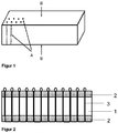
Figur 1 zeigt das regelmäßige Durchsticken von kapillaraktiven Dochten in eine Wärmedämmplatte, die umseitig mit einem kapillaraktiven Stoff kaschiert ist. Der erhaltene erfindungsgemäße Wärmedämmformkörper weist eine erhöhte Zugfestigkeit und eine niedrige Wärmeleitfähigkeit auf. A= regelmäßiges Durchsticken von kapillaraktiven Dochten; B = umseitige Kaschierung mit kapillaraktivem Stoff, beispielsweise Gewebe oder Kombination mit Mörtel. -
Figur 2 zeigt einen durch Tufting hergestellten Wärmedämmformkörper, dessen wärmedämmender, nicht kapillaraktiver Kern eine Wärmedämmplatte (1) ist, die hydrophobierte Kieselsäure und ein IR-Trübungsmittel enthält,
dessen kapillaraktive Deckschicht aus Mineralwolle (2) besteht und
dessen kapillaraktiven Dochte Glasfasern (3) umfassen. - Die mechanische Endfestigkeit kann durch Verkleben an der Wand, indem die Ösen flächig miteinander verbunden oder zumindest lokal verklebt werden, erhöht werden.
-
Figur 3 zeigt die Wirkung der kapillaraktiven Dochte. Hierzu wird ein Wärmedämmformkörper in eine mit Wasser gefüllte Wanne gegeben. Der Wärmedämmformkörper schwimmt mit einem kleinen Spalt zum Rand der Wanne um die freie Konvektion/Verdunstung zu minimieren und um immer einen guten Kontakt zum Wasser zu gewährleisten. Die Anordnung steht auf einer Waage. Bei definierten Strömungsverhältnissen in einem Abzug bei 22°C wird gleichzeitig die Massenabnahme mit der Zeit gemessen. Der Wärmedämmformkörper ist - a) eine hydrophobe, diffusionsoffene Platte (200x200x35mm), deren Hauptbestandteil eine hydrophobierte, pyrogene Kieselsäure (CALOSTAT®, Evonik Industries) ist. Der Wasserdampf muß durch die Platte diffundieren bevor es zur freien Konvektion oberhalb kommt. In
Figur 3 sind die Werte mit o markiert. - b) eine CALOSTAT®-Platte mit 3 kapillaraktiven Dochten und mit einem kapillaraktiven Deckvlies (170x200mm). Jeder Docht besteht aus ca. 7000 Einzelfäden aus Glas mit einem Durchmesser von ca. 10µm. In
Figur 3 sind die Werte mit x markiert. Hier wird das Wasser durch die Dochte in die Deckschicht befördert, wo Verdunstung mit freier oder erzwungener Konvektion aufgrund des Abzuges vorliegt. Die Verdunstungsrate ist mit Dochten ca. dreimal so groß wie ohne kapillaraktiven Dochte. Die 3 kapillaraktiven Dochte reichen bereits vollkommen aus, um das Deckvlies dauerhaft zu benetzen. InFigur 3 ist die verdunstete Wassermenge in Gramm gegen die Zeit in Minuten aufgetragen. -
Figur 4 zeigt eine berechnete Wärmeleitfähigkeit und Zugfestigkeit eines gesteppten Wärmedämmformkörpers umfassend eine nicht kapillaraktiven, diffusionsoffene Wärmedämmplatte, CALOSTAT®, und eine kapillaraktive Deckschicht und kapillaraktive Dochte. Bei der Zugfestigkeit wird die Annahme gemacht, dass alle kapillaraktiven Dochte bis zur Zerreißgrenze halten und es keine Fehlstellen gibt, die kapillaraktiven Dochte aus Glasfasern (Zugfestigkeit 3000MPa) sind und die Zugfestigkeit von CALOSTAT® 0 kPa ist. Weiterhin werden die kapillaraktiven Deckschichten vereinfacht mit der Dicke d=0 angenommen. InFigur 4 steht die x-Achse für die Anzahl Fäden (Durchmesser des Einzelfadens = 10 µm) pro Docht, linke y-Achse für Lambda in W/(mK) (Markierung inFigur 4 : Raute): , rechte y-Achse für die Zugfestigkeit in kPa (Markierung inFigur 4 : Quadrat). - Ausgehend von 20 mW/(mK) für den nicht kapillaraktiven, wärmedämmenden Kern erhöht sich die Wärmeleitfähigkeit mit zunehmender Anzahl an kapillaraktiven Dochten. Die kapillaraktiven Dochte werden hierbei in einem Raster von 4x5cm2 gesteppt. Variiert wird die Anzahl der einzelnen Fäden pro Docht. Erst bei 10000 Fäden pro Docht steigt die Wärmeleitfähigkeit um knapp 0,5 mW/(mK). Dies entspricht einem effektiven Dochtquerschnitt von 0,8 mm. Das gewählte Raster hat 500 Dochte pro Quadratmeter zur Folge. Während die Wärmedämmung also nur gering abnimmt, nimmt die Zugfestigkeit deutlich zu.
- Eine reale Messung für einen gesteppten Wärmedämmformkörper aus einer CALOSTAT®-Platte mit einer Dicke von 30 mm, kapillaraktiven Dochten, wie in der Beschreibung zu
Figur 3 angegeben, und mit 12 mm Mineralwolle, Akustic EP3 ISOVER St. GOBAIN, als beidseitige Deckschicht ergibt eine effektive Wärmeleitfähigkeit von 0,024 W/(mK) Die Messung wurde mit einem Plattengerät bei 10°C Mitteltemperatur und einem Anpressdruck von 2000 Pa durchgeführt. Der rechnerische Wert liegt bei 0,025 W/(mK). Dies zeigt die gute Übereinstimmung von Theorie und Praxis.
Claims (13)
- Wärmedämmformkörper, der einen Lochungen aufweisenden, wärmedämmenden Kern umfasst und diese Lochungen mit einem kapillaraktiven Material befüllt sind, wobei der wärmedämmende Kern nicht kapillaraktiv ist und das kapillaraktive Material in den Lochungen kapillaraktive Dochte umfasst, dadurch gekennzeichnet, dass die Querschnittsfläche der kapillaraktiven Dochte von 0,001 bis 1 mm2 beträgt.
- Wärmedämmformkörper nach Anspruch 1,
dadurch gekennzeichnet, dass
die Lochungen einen Durchmesser von 100 bis 6000 µm aufweisen. - Wärmedämmformkörper nach den Ansprüchen 1 oder 2,
dadurch gekennzeichnet, dass
die kapillaraktiven Dochte eine Flächendichte von 10 bis 10000 Stück/m2 aufweisen. - Wärmedämmformkörper nach den Ansprüchen 1 bis 3,
dadurch gekennzeichnet, dass
die kapillaraktiven Dochte Garne Zwirne, Fäden, texturierter Spinnfaden, Filamente und Kordeln umfassen. - Wärmedämmformkörper nach den Ansprüchen 1 bis 4,
dadurch gekennzeichnet, dass
das Material der kapillaraktiven Dochte ausgewählt ist aus der Gruppe bestehend aus Basalt, Silika, E-Glas, C-Glas und Glas. - Wärmedämmformkörper nach den Ansprüchen 1 bis 5,
dadurch gekennzeichnet, dass
die kapillaraktiven Dochte aus dem Wärmedämmformkörper herausragen oder bündig mit der Oberfläche des Wärmedämmformkörpers enden. - Wärmedämmformkörper nach den Ansprüchen 1 bis 6,
dadurch gekennzeichnet, dass
der wärmedämmende, nicht kapillaraktive Kern eine Wärmedämmplatte, eine Wärmedämmmatte oder eine Wärmedämmschüttung ist. - Wärmedämmformkörper nach den Ansprüchen 1 bis 7,
dadurch gekennzeichnet,
dass die Dicke des wärmedämmenden, nicht kapillaraktiven Kerns 3 bis 150 mm beträgt. - Wärmedämmformkörper nach den Ansprüchen 1 bis 8,
dadurch gekennzeichnet, dass
der wärmedämmende, nicht kapillaraktive Kern eine Wärmeleitfähigkeit von weniger als 0,025 W/(mK) aufweist. - Wärmedämmformkörper nach den Ansprüchen 1 bis 9,
dadurch gekennzeichnet, dass
der wärmedämmende, nicht kapillaraktive Kern hydrophobe, pyrogene Kieselsäure enthält. - Wärmedämmformkörper nach den Ansprüchen 1 bis 10,
dadurch gekennzeichnet, dass
er wenigstens eine ein- oder beidseitig des wärmedämmenden, nicht kapillaraktiven Kerns angebrachte kapillaraktive Deckschicht umfasst, wobei die kapillaraktiven Dochte in der kapillaraktiven Deckschicht enden oder aus ihr herausragen. - Wärmedämmformkörper nach Anspruch 11,
dadurch gekennzeichnet, dass
das Material der kapillaraktiven Deckschicht ausgewählt ist aus der Gruppe bestehend aus einem kapillar aktiven textilen Flächengebilde , einem kapillar aktiven offenporigen Schaum und/oder einer kapillar aktiven porösen Schicht. - Wärmedämmformkörper nach den Ansprüchen 11 oder 12,
dadurch gekennzeichnet, dass
er zwischen dem wärmedämmenden, nicht kapillaraktiven Kern und der kapillaraktiven Deckschicht eine als Dampfsperre oder Dampfbremse wirkende Schicht aufweist, durch die die kapillaraktiven Dochte geführt werden.
Applications Claiming Priority (2)
| Application Number | Priority Date | Filing Date | Title |
|---|---|---|---|
| EP15151456.9A EP3045600A1 (de) | 2015-01-16 | 2015-01-16 | Kapillaraktive Elemente umfassender Wärmedämmformkörper |
| PCT/EP2016/050329 WO2016113204A1 (de) | 2015-01-16 | 2016-01-11 | Kapillaraktive elemente umfassender wärmedämmformkörper |
Publications (2)
| Publication Number | Publication Date |
|---|---|
| EP3245343A1 EP3245343A1 (de) | 2017-11-22 |
| EP3245343B1 true EP3245343B1 (de) | 2020-05-06 |
Family
ID=52350023
Family Applications (2)
| Application Number | Title | Priority Date | Filing Date |
|---|---|---|---|
| EP15151456.9A Withdrawn EP3045600A1 (de) | 2015-01-16 | 2015-01-16 | Kapillaraktive Elemente umfassender Wärmedämmformkörper |
| EP16700262.5A Active EP3245343B1 (de) | 2015-01-16 | 2016-01-11 | Kapillaraktive elemente umfassender wärmedämmformkörper |
Family Applications Before (1)
| Application Number | Title | Priority Date | Filing Date |
|---|---|---|---|
| EP15151456.9A Withdrawn EP3045600A1 (de) | 2015-01-16 | 2015-01-16 | Kapillaraktive Elemente umfassender Wärmedämmformkörper |
Country Status (4)
| Country | Link |
|---|---|
| US (1) | US20170268221A1 (de) |
| EP (2) | EP3045600A1 (de) |
| CA (1) | CA2968083A1 (de) |
| WO (1) | WO2016113204A1 (de) |
Families Citing this family (10)
| Publication number | Priority date | Publication date | Assignee | Title |
|---|---|---|---|---|
| US11427506B2 (en) | 2016-07-29 | 2022-08-30 | Evonik Operations Gmbh | Method for producing hydrophobic heat insulation material |
| EP3571173A1 (de) | 2017-01-18 | 2019-11-27 | Evonik Degussa GmbH | Granulares wärmedämmungsmaterial und verfahren zur dessen herstellung |
| DE102017209782A1 (de) | 2017-06-09 | 2018-12-13 | Evonik Degussa Gmbh | Verfahren zur Wärmedämmung eines evakuierbaren Behälters |
| EP3762137A1 (de) | 2018-03-05 | 2021-01-13 | Evonik Operations GmbH | Verfahren zur herstellung eines aerogelmaterials |
| DE102018112260A1 (de) * | 2018-05-22 | 2019-11-28 | Saint-Gobain Isover G+H Ag | Wärmedämmelement, Bauwerkskonstruktion sowie Verfahren zur Vermeidung von Feuchteschäden an einem Bauwerk |
| EP3597615A1 (de) | 2018-07-17 | 2020-01-22 | Evonik Operations GmbH | Körniges gemischtes oxidmaterial und wärmedämmungszusammensetzung auf dessen basis |
| EP3823939A1 (de) | 2018-07-17 | 2021-05-26 | Evonik Operations GmbH | Wärmedämmende zusammensetzung auf basis pyrogener kieselsäuregranulate, verfahren zu deren herstellung und verwendungen davon |
| WO2020016036A1 (en) | 2018-07-18 | 2020-01-23 | Evonik Operations Gmbh | Process for hydrophobizing shaped insulation-material bodies based on silica at ambient pressure |
| ES3043559T3 (en) | 2020-01-14 | 2025-11-25 | Evonik Operations Gmbh | Silica-based hydrophobic granular material with an increased polarity |
| EP4143134B1 (de) | 2020-04-30 | 2025-06-25 | Evonik Operations GmbH | Verfahren zur herstellung eines kieselsäureaerogels mit erhöhter alkalistabilität |
Family Cites Families (6)
| Publication number | Priority date | Publication date | Assignee | Title |
|---|---|---|---|---|
| DE202005005231U1 (de) | 2005-03-31 | 2005-08-04 | Haacke Treuhand Gmbh Celle + Co. Kg | Fachwerkbauten |
| DE102007040938B4 (de) | 2007-08-30 | 2023-09-21 | Remmers Baustofftechnik Gmbh | Wandaufbau und Wärmedämmplatte |
| WO2013013714A1 (de) | 2011-07-27 | 2013-01-31 | Evonik Degussa Gmbh | Verfahren zur herstellung hydrophober, wärmedämmender formkörper |
| DK2898154T3 (da) | 2012-09-22 | 2021-01-25 | Evonik Operations Gmbh | Vægopbygning til indvendige isoleringssystemer med installerede varmeisoleringsplader ved variable fugeafstande |
| EP2765251B1 (de) * | 2013-02-12 | 2016-12-28 | Daw Se | Plattenförmiger Wärmedämmverbund und Wärmedämmverbundareal, insbesondere Wärmedämmplattenareal, umfassend plattenförmigen Wärmedämmverbünde, sowie Verfahren zur Herstellung von Wärmedämmverbünden und Verwendung von Wärmedämmverbünden für die Wärmedämmung von Gebäuden |
| CN103936349B (zh) * | 2014-03-26 | 2016-08-17 | 广州吉必盛科技实业有限公司 | 疏水型气相SiO2纳米孔绝热材料及其制备方法 |
-
2015
- 2015-01-16 EP EP15151456.9A patent/EP3045600A1/de not_active Withdrawn
-
2016
- 2016-01-11 EP EP16700262.5A patent/EP3245343B1/de active Active
- 2016-01-11 WO PCT/EP2016/050329 patent/WO2016113204A1/de not_active Ceased
- 2016-01-11 CA CA2968083A patent/CA2968083A1/en not_active Abandoned
- 2016-01-11 US US15/531,478 patent/US20170268221A1/en not_active Abandoned
Non-Patent Citations (1)
| Title |
|---|
| None * |
Also Published As
| Publication number | Publication date |
|---|---|
| EP3045600A1 (de) | 2016-07-20 |
| CA2968083A1 (en) | 2016-07-21 |
| US20170268221A1 (en) | 2017-09-21 |
| EP3245343A1 (de) | 2017-11-22 |
| WO2016113204A1 (de) | 2016-07-21 |
Similar Documents
| Publication | Publication Date | Title |
|---|---|---|
| WO2016113204A1 (de) | Kapillaraktive elemente umfassender wärmedämmformkörper | |
| DE60122228T2 (de) | Gegen Durchbrennen widerstandsfähige, nicht gewebte Matte, Sperrschicht und Dämmsystem | |
| EP2183099B2 (de) | Wandaufbau und wärmedämmplatte | |
| DE4108110C2 (de) | Wärmedämmaterial für Gebäude | |
| EP3257902A1 (de) | Beschichtungsmasse sowie putzbeschichtung und dämmendes bauteil | |
| EP2898154B1 (de) | Wandaufbau mit einem innendämmungssysteme mit verlegten wärmedämmplatten bei variablen fugenabständen | |
| DE60314551T2 (de) | Verfahren zur Wärmedämung | |
| EP3045306B1 (de) | Decklage, dämmplatte und wärme-dämm-verbundsystem | |
| DE202009008493U1 (de) | Wandaufbau und Wärmedämmplatte | |
| EP0591658B1 (de) | Wärmedämmelement und Verfahren zu dessen Herstellung | |
| DE4223614A1 (de) | Dämmstoff sowie Verfahren zu seiner Herstellung | |
| DE19734532C2 (de) | Dämmelement | |
| DE102009004364A1 (de) | Wand- oder Deckenbelag | |
| EP2369078B1 (de) | Isolationsmaterial | |
| EP3249084A1 (de) | Verfahren zur herstellung eines garnes, verfahren zur herstellung eines vlieses und vlies | |
| EP2910672B1 (de) | Unterdeckplatte | |
| DE9319699U1 (de) | Wärmedämmelement | |
| WO2015101656A1 (de) | Wandinnenplatte | |
| DE4316696A1 (de) | Verfahren zur Herstellung von Bauelementen aus Naturfasern und dauerhaften Gestaltung von Gebäudefassaden und Oberflächen tragender Konstruktionen sowie Elemente hierfür | |
| EP2855142B1 (de) | Bauplatte | |
| EP1152094A1 (de) | Verfahren zur Herstellung von Dämmelementen | |
| DE9217604U1 (de) | Dämmelement aus Flachsfasern zur Wärmedämmung | |
| DE29700241U1 (de) | Mineralfaserdämmplatten mit überwiegend schräg zu ihren großen Oberflächen verlaufenden Fasern | |
| DE102020131043A1 (de) | Lehmbaustein und Lehmbausteinsystem | |
| AT364499B (de) | Waermeisolierende mauerverkleidung |
Legal Events
| Date | Code | Title | Description |
|---|---|---|---|
| STAA | Information on the status of an ep patent application or granted ep patent |
Free format text: STATUS: THE INTERNATIONAL PUBLICATION HAS BEEN MADE |
|
| PUAI | Public reference made under article 153(3) epc to a published international application that has entered the european phase |
Free format text: ORIGINAL CODE: 0009012 |
|
| STAA | Information on the status of an ep patent application or granted ep patent |
Free format text: STATUS: REQUEST FOR EXAMINATION WAS MADE |
|
| 17P | Request for examination filed |
Effective date: 20170712 |
|
| AK | Designated contracting states |
Kind code of ref document: A1 Designated state(s): AL AT BE BG CH CY CZ DE DK EE ES FI FR GB GR HR HU IE IS IT LI LT LU LV MC MK MT NL NO PL PT RO RS SE SI SK SM TR |
|
| AX | Request for extension of the european patent |
Extension state: BA ME |
|
| DAV | Request for validation of the european patent (deleted) | ||
| DAX | Request for extension of the european patent (deleted) | ||
| RAP1 | Party data changed (applicant data changed or rights of an application transferred) |
Owner name: EVONIK DEGUSSA GMBH |
|
| STAA | Information on the status of an ep patent application or granted ep patent |
Free format text: STATUS: EXAMINATION IS IN PROGRESS |
|
| RAP1 | Party data changed (applicant data changed or rights of an application transferred) |
Owner name: EVONIK OPERATIONS GMBH |
|
| 17Q | First examination report despatched |
Effective date: 20191128 |
|
| GRAP | Despatch of communication of intention to grant a patent |
Free format text: ORIGINAL CODE: EPIDOSNIGR1 |
|
| STAA | Information on the status of an ep patent application or granted ep patent |
Free format text: STATUS: GRANT OF PATENT IS INTENDED |
|
| GRAS | Grant fee paid |
Free format text: ORIGINAL CODE: EPIDOSNIGR3 |
|
| INTG | Intention to grant announced |
Effective date: 20200226 |
|
| GRAA | (expected) grant |
Free format text: ORIGINAL CODE: 0009210 |
|
| STAA | Information on the status of an ep patent application or granted ep patent |
Free format text: STATUS: THE PATENT HAS BEEN GRANTED |
|
| AK | Designated contracting states |
Kind code of ref document: B1 Designated state(s): AL AT BE BG CH CY CZ DE DK EE ES FI FR GB GR HR HU IE IS IT LI LT LU LV MC MK MT NL NO PL PT RO RS SE SI SK SM TR |
|
| REG | Reference to a national code |
Ref country code: GB Ref legal event code: FG4D Free format text: NOT ENGLISH |
|
| REG | Reference to a national code |
Ref country code: AT Ref legal event code: REF Ref document number: 1266942 Country of ref document: AT Kind code of ref document: T Effective date: 20200515 Ref country code: CH Ref legal event code: EP |
|
| REG | Reference to a national code |
Ref country code: IE Ref legal event code: FG4D Free format text: LANGUAGE OF EP DOCUMENT: GERMAN |
|
| REG | Reference to a national code |
Ref country code: DE Ref legal event code: R096 Ref document number: 502016009847 Country of ref document: DE |
|
| REG | Reference to a national code |
Ref country code: NL Ref legal event code: FP |
|
| REG | Reference to a national code |
Ref country code: LT Ref legal event code: MG4D |
|
| PG25 | Lapsed in a contracting state [announced via postgrant information from national office to epo] |
Ref country code: PT Free format text: LAPSE BECAUSE OF FAILURE TO SUBMIT A TRANSLATION OF THE DESCRIPTION OR TO PAY THE FEE WITHIN THE PRESCRIBED TIME-LIMIT Effective date: 20200907 Ref country code: FI Free format text: LAPSE BECAUSE OF FAILURE TO SUBMIT A TRANSLATION OF THE DESCRIPTION OR TO PAY THE FEE WITHIN THE PRESCRIBED TIME-LIMIT Effective date: 20200506 Ref country code: SE Free format text: LAPSE BECAUSE OF FAILURE TO SUBMIT A TRANSLATION OF THE DESCRIPTION OR TO PAY THE FEE WITHIN THE PRESCRIBED TIME-LIMIT Effective date: 20200506 Ref country code: LT Free format text: LAPSE BECAUSE OF FAILURE TO SUBMIT A TRANSLATION OF THE DESCRIPTION OR TO PAY THE FEE WITHIN THE PRESCRIBED TIME-LIMIT Effective date: 20200506 Ref country code: IS Free format text: LAPSE BECAUSE OF FAILURE TO SUBMIT A TRANSLATION OF THE DESCRIPTION OR TO PAY THE FEE WITHIN THE PRESCRIBED TIME-LIMIT Effective date: 20200906 Ref country code: GR Free format text: LAPSE BECAUSE OF FAILURE TO SUBMIT A TRANSLATION OF THE DESCRIPTION OR TO PAY THE FEE WITHIN THE PRESCRIBED TIME-LIMIT Effective date: 20200807 Ref country code: NO Free format text: LAPSE BECAUSE OF FAILURE TO SUBMIT A TRANSLATION OF THE DESCRIPTION OR TO PAY THE FEE WITHIN THE PRESCRIBED TIME-LIMIT Effective date: 20200806 |
|
| PG25 | Lapsed in a contracting state [announced via postgrant information from national office to epo] |
Ref country code: RS Free format text: LAPSE BECAUSE OF FAILURE TO SUBMIT A TRANSLATION OF THE DESCRIPTION OR TO PAY THE FEE WITHIN THE PRESCRIBED TIME-LIMIT Effective date: 20200506 Ref country code: BG Free format text: LAPSE BECAUSE OF FAILURE TO SUBMIT A TRANSLATION OF THE DESCRIPTION OR TO PAY THE FEE WITHIN THE PRESCRIBED TIME-LIMIT Effective date: 20200806 Ref country code: LV Free format text: LAPSE BECAUSE OF FAILURE TO SUBMIT A TRANSLATION OF THE DESCRIPTION OR TO PAY THE FEE WITHIN THE PRESCRIBED TIME-LIMIT Effective date: 20200506 Ref country code: HR Free format text: LAPSE BECAUSE OF FAILURE TO SUBMIT A TRANSLATION OF THE DESCRIPTION OR TO PAY THE FEE WITHIN THE PRESCRIBED TIME-LIMIT Effective date: 20200506 |
|
| PG25 | Lapsed in a contracting state [announced via postgrant information from national office to epo] |
Ref country code: AL Free format text: LAPSE BECAUSE OF FAILURE TO SUBMIT A TRANSLATION OF THE DESCRIPTION OR TO PAY THE FEE WITHIN THE PRESCRIBED TIME-LIMIT Effective date: 20200506 |
|
| PG25 | Lapsed in a contracting state [announced via postgrant information from national office to epo] |
Ref country code: DK Free format text: LAPSE BECAUSE OF FAILURE TO SUBMIT A TRANSLATION OF THE DESCRIPTION OR TO PAY THE FEE WITHIN THE PRESCRIBED TIME-LIMIT Effective date: 20200506 Ref country code: SM Free format text: LAPSE BECAUSE OF FAILURE TO SUBMIT A TRANSLATION OF THE DESCRIPTION OR TO PAY THE FEE WITHIN THE PRESCRIBED TIME-LIMIT Effective date: 20200506 Ref country code: EE Free format text: LAPSE BECAUSE OF FAILURE TO SUBMIT A TRANSLATION OF THE DESCRIPTION OR TO PAY THE FEE WITHIN THE PRESCRIBED TIME-LIMIT Effective date: 20200506 Ref country code: CZ Free format text: LAPSE BECAUSE OF FAILURE TO SUBMIT A TRANSLATION OF THE DESCRIPTION OR TO PAY THE FEE WITHIN THE PRESCRIBED TIME-LIMIT Effective date: 20200506 Ref country code: IT Free format text: LAPSE BECAUSE OF FAILURE TO SUBMIT A TRANSLATION OF THE DESCRIPTION OR TO PAY THE FEE WITHIN THE PRESCRIBED TIME-LIMIT Effective date: 20200506 Ref country code: RO Free format text: LAPSE BECAUSE OF FAILURE TO SUBMIT A TRANSLATION OF THE DESCRIPTION OR TO PAY THE FEE WITHIN THE PRESCRIBED TIME-LIMIT Effective date: 20200506 Ref country code: ES Free format text: LAPSE BECAUSE OF FAILURE TO SUBMIT A TRANSLATION OF THE DESCRIPTION OR TO PAY THE FEE WITHIN THE PRESCRIBED TIME-LIMIT Effective date: 20200506 |
|
| REG | Reference to a national code |
Ref country code: DE Ref legal event code: R097 Ref document number: 502016009847 Country of ref document: DE |
|
| PG25 | Lapsed in a contracting state [announced via postgrant information from national office to epo] |
Ref country code: PL Free format text: LAPSE BECAUSE OF FAILURE TO SUBMIT A TRANSLATION OF THE DESCRIPTION OR TO PAY THE FEE WITHIN THE PRESCRIBED TIME-LIMIT Effective date: 20200506 Ref country code: SK Free format text: LAPSE BECAUSE OF FAILURE TO SUBMIT A TRANSLATION OF THE DESCRIPTION OR TO PAY THE FEE WITHIN THE PRESCRIBED TIME-LIMIT Effective date: 20200506 |
|
| PLBE | No opposition filed within time limit |
Free format text: ORIGINAL CODE: 0009261 |
|
| STAA | Information on the status of an ep patent application or granted ep patent |
Free format text: STATUS: NO OPPOSITION FILED WITHIN TIME LIMIT |
|
| 26N | No opposition filed |
Effective date: 20210209 |
|
| PG25 | Lapsed in a contracting state [announced via postgrant information from national office to epo] |
Ref country code: SI Free format text: LAPSE BECAUSE OF FAILURE TO SUBMIT A TRANSLATION OF THE DESCRIPTION OR TO PAY THE FEE WITHIN THE PRESCRIBED TIME-LIMIT Effective date: 20200506 |
|
| PG25 | Lapsed in a contracting state [announced via postgrant information from national office to epo] |
Ref country code: MC Free format text: LAPSE BECAUSE OF FAILURE TO SUBMIT A TRANSLATION OF THE DESCRIPTION OR TO PAY THE FEE WITHIN THE PRESCRIBED TIME-LIMIT Effective date: 20200506 |
|
| GBPC | Gb: european patent ceased through non-payment of renewal fee |
Effective date: 20210111 |
|
| PG25 | Lapsed in a contracting state [announced via postgrant information from national office to epo] |
Ref country code: GB Free format text: LAPSE BECAUSE OF NON-PAYMENT OF DUE FEES Effective date: 20210111 |
|
| PG25 | Lapsed in a contracting state [announced via postgrant information from national office to epo] |
Ref country code: IE Free format text: LAPSE BECAUSE OF NON-PAYMENT OF DUE FEES Effective date: 20210111 |
|
| PG25 | Lapsed in a contracting state [announced via postgrant information from national office to epo] |
Ref country code: HU Free format text: LAPSE BECAUSE OF FAILURE TO SUBMIT A TRANSLATION OF THE DESCRIPTION OR TO PAY THE FEE WITHIN THE PRESCRIBED TIME-LIMIT; INVALID AB INITIO Effective date: 20160111 |
|
| PG25 | Lapsed in a contracting state [announced via postgrant information from national office to epo] |
Ref country code: CY Free format text: LAPSE BECAUSE OF FAILURE TO SUBMIT A TRANSLATION OF THE DESCRIPTION OR TO PAY THE FEE WITHIN THE PRESCRIBED TIME-LIMIT Effective date: 20200506 |
|
| P01 | Opt-out of the competence of the unified patent court (upc) registered |
Effective date: 20230818 |
|
| PGFP | Annual fee paid to national office [announced via postgrant information from national office to epo] |
Ref country code: FR Payment date: 20231208 Year of fee payment: 9 |
|
| REG | Reference to a national code |
Ref country code: DE Ref legal event code: R081 Ref document number: 502016009847 Country of ref document: DE Owner name: KINGSPAN INSULATION LIMITED, LEOMINSTER, GB Free format text: FORMER OWNER: EVONIK OPERATIONS GMBH, 45128 ESSEN, DE |
|
| PGFP | Annual fee paid to national office [announced via postgrant information from national office to epo] |
Ref country code: NL Payment date: 20240125 Year of fee payment: 9 |
|
| PGFP | Annual fee paid to national office [announced via postgrant information from national office to epo] |
Ref country code: LU Payment date: 20240125 Year of fee payment: 9 |
|
| PGFP | Annual fee paid to national office [announced via postgrant information from national office to epo] |
Ref country code: AT Payment date: 20240118 Year of fee payment: 9 |
|
| PG25 | Lapsed in a contracting state [announced via postgrant information from national office to epo] |
Ref country code: MK Free format text: LAPSE BECAUSE OF FAILURE TO SUBMIT A TRANSLATION OF THE DESCRIPTION OR TO PAY THE FEE WITHIN THE PRESCRIBED TIME-LIMIT Effective date: 20200506 |
|
| PGFP | Annual fee paid to national office [announced via postgrant information from national office to epo] |
Ref country code: DE Payment date: 20231211 Year of fee payment: 9 Ref country code: CH Payment date: 20240202 Year of fee payment: 9 |
|
| PGFP | Annual fee paid to national office [announced via postgrant information from national office to epo] |
Ref country code: BE Payment date: 20240125 Year of fee payment: 9 |
|
| PG25 | Lapsed in a contracting state [announced via postgrant information from national office to epo] |
Ref country code: MT Free format text: LAPSE BECAUSE OF FAILURE TO SUBMIT A TRANSLATION OF THE DESCRIPTION OR TO PAY THE FEE WITHIN THE PRESCRIBED TIME-LIMIT Effective date: 20200506 |
|
| REG | Reference to a national code |
Ref country code: DE Ref legal event code: R119 Ref document number: 502016009847 Country of ref document: DE |
|
| REG | Reference to a national code |
Ref country code: CH Ref legal event code: PL |
|
| REG | Reference to a national code |
Ref country code: NL Ref legal event code: MM Effective date: 20250201 |
|
| PG25 | Lapsed in a contracting state [announced via postgrant information from national office to epo] |
Ref country code: LU Free format text: LAPSE BECAUSE OF NON-PAYMENT OF DUE FEES Effective date: 20250111 |
|
| REG | Reference to a national code |
Ref country code: AT Ref legal event code: MM01 Ref document number: 1266942 Country of ref document: AT Kind code of ref document: T Effective date: 20250111 |
|
| PG25 | Lapsed in a contracting state [announced via postgrant information from national office to epo] |
Ref country code: DE Free format text: LAPSE BECAUSE OF NON-PAYMENT OF DUE FEES Effective date: 20250801 |
|
| PG25 | Lapsed in a contracting state [announced via postgrant information from national office to epo] |
Ref country code: NL Free format text: LAPSE BECAUSE OF NON-PAYMENT OF DUE FEES Effective date: 20250201 |
|
| PG25 | Lapsed in a contracting state [announced via postgrant information from national office to epo] |
Ref country code: BE Free format text: LAPSE BECAUSE OF NON-PAYMENT OF DUE FEES Effective date: 20250131 |
|
| PG25 | Lapsed in a contracting state [announced via postgrant information from national office to epo] |
Ref country code: FR Free format text: LAPSE BECAUSE OF NON-PAYMENT OF DUE FEES Effective date: 20250131 Ref country code: AT Free format text: LAPSE BECAUSE OF NON-PAYMENT OF DUE FEES Effective date: 20250111 |
|
| PG25 | Lapsed in a contracting state [announced via postgrant information from national office to epo] |
Ref country code: CH Free format text: LAPSE BECAUSE OF NON-PAYMENT OF DUE FEES Effective date: 20250131 |
|
| REG | Reference to a national code |
Ref country code: BE Ref legal event code: MM Effective date: 20250131 |
|
| PG25 | Lapsed in a contracting state [announced via postgrant information from national office to epo] |
Ref country code: TR Free format text: LAPSE BECAUSE OF FAILURE TO SUBMIT A TRANSLATION OF THE DESCRIPTION OR TO PAY THE FEE WITHIN THE PRESCRIBED TIME-LIMIT Effective date: 20200506 |