EP3244283B1 - Einstellbare halterung für tragbare vorrichtung - Google Patents
Einstellbare halterung für tragbare vorrichtung Download PDFInfo
- Publication number
- EP3244283B1 EP3244283B1 EP17178044.8A EP17178044A EP3244283B1 EP 3244283 B1 EP3244283 B1 EP 3244283B1 EP 17178044 A EP17178044 A EP 17178044A EP 3244283 B1 EP3244283 B1 EP 3244283B1
- Authority
- EP
- European Patent Office
- Prior art keywords
- mounting
- adjustable
- clamping element
- portable device
- device holder
- Prior art date
- Legal status (The legal status is an assumption and is not a legal conclusion. Google has not performed a legal analysis and makes no representation as to the accuracy of the status listed.)
- Not-in-force
Links
Images

Classifications
-
- H—ELECTRICITY
- H04—ELECTRIC COMMUNICATION TECHNIQUE
- H04M—TELEPHONIC COMMUNICATION
- H04M1/00—Substation equipment, e.g. for use by subscribers
- H04M1/02—Constructional features of telephone sets
- H04M1/04—Supports for telephone transmitters or receivers
-
- F—MECHANICAL ENGINEERING; LIGHTING; HEATING; WEAPONS; BLASTING
- F16—ENGINEERING ELEMENTS AND UNITS; GENERAL MEASURES FOR PRODUCING AND MAINTAINING EFFECTIVE FUNCTIONING OF MACHINES OR INSTALLATIONS; THERMAL INSULATION IN GENERAL
- F16M—FRAMES, CASINGS OR BEDS OF ENGINES, MACHINES OR APPARATUS, NOT SPECIFIC TO ENGINES, MACHINES OR APPARATUS PROVIDED FOR ELSEWHERE; STANDS; SUPPORTS
- F16M11/00—Stands or trestles as supports for apparatus or articles placed thereon ; Stands for scientific apparatus such as gravitational force meters
- F16M11/02—Heads
- F16M11/04—Means for attachment of apparatus; Means allowing adjustment of the apparatus relatively to the stand
-
- B—PERFORMING OPERATIONS; TRANSPORTING
- B60—VEHICLES IN GENERAL
- B60R—VEHICLES, VEHICLE FITTINGS, OR VEHICLE PARTS, NOT OTHERWISE PROVIDED FOR
- B60R11/00—Arrangements for holding or mounting articles, not otherwise provided for
- B60R11/02—Arrangements for holding or mounting articles, not otherwise provided for for radio sets, television sets, telephones, or the like; Arrangement of controls thereof
-
- B—PERFORMING OPERATIONS; TRANSPORTING
- B60—VEHICLES IN GENERAL
- B60R—VEHICLES, VEHICLE FITTINGS, OR VEHICLE PARTS, NOT OTHERWISE PROVIDED FOR
- B60R11/00—Arrangements for holding or mounting articles, not otherwise provided for
- B60R2011/0001—Arrangements for holding or mounting articles, not otherwise provided for characterised by position
- B60R2011/0003—Arrangements for holding or mounting articles, not otherwise provided for characterised by position inside the vehicle
- B60R2011/0008—Ventilation grilles
-
- B—PERFORMING OPERATIONS; TRANSPORTING
- B60—VEHICLES IN GENERAL
- B60R—VEHICLES, VEHICLE FITTINGS, OR VEHICLE PARTS, NOT OTHERWISE PROVIDED FOR
- B60R11/00—Arrangements for holding or mounting articles, not otherwise provided for
- B60R2011/0042—Arrangements for holding or mounting articles, not otherwise provided for characterised by mounting means
- B60R2011/0049—Arrangements for holding or mounting articles, not otherwise provided for characterised by mounting means for non integrated articles
- B60R2011/005—Connection with the vehicle part
- B60R2011/0059—Connection with the vehicle part using clips, clamps, straps or the like
-
- B—PERFORMING OPERATIONS; TRANSPORTING
- B60—VEHICLES IN GENERAL
- B60R—VEHICLES, VEHICLE FITTINGS, OR VEHICLE PARTS, NOT OTHERWISE PROVIDED FOR
- B60R11/00—Arrangements for holding or mounting articles, not otherwise provided for
- B60R2011/0042—Arrangements for holding or mounting articles, not otherwise provided for characterised by mounting means
- B60R2011/0049—Arrangements for holding or mounting articles, not otherwise provided for characterised by mounting means for non integrated articles
- B60R2011/0064—Connection with the article
- B60R2011/0071—Connection with the article using latches, clips, clamps, straps or the like
-
- B—PERFORMING OPERATIONS; TRANSPORTING
- B60—VEHICLES IN GENERAL
- B60R—VEHICLES, VEHICLE FITTINGS, OR VEHICLE PARTS, NOT OTHERWISE PROVIDED FOR
- B60R11/00—Arrangements for holding or mounting articles, not otherwise provided for
- B60R2011/0042—Arrangements for holding or mounting articles, not otherwise provided for characterised by mounting means
- B60R2011/008—Adjustable or movable supports
- B60R2011/0085—Adjustable or movable supports with adjustment by rotation in their operational position
Definitions
- the present application is directed to adjustable portable device holder systems and methods.
- This specification is directed to improved portable device holder systems and methods for manufacturing the same.
- an adjustable portable device holder includes an adjustable clamping element and a rotatable mounting element attached to the adjustable clamping element for removably securing a portable device to the adjustable portable device holder.
- the adjustable clamping element is capable of being biased into an activated state and unbiased into a deactivated state to secure one of a plurality of different size portable devices to the adjustable portable device holder.
- the rotatable mounting element, attached to the adjustable clamping element includes a plurality of mounting arms each spaced a specified distance apart from one another and extending at a specified angle from a bottom surface of the rotatable mounting element. Each pair of the plurality of mounting arms forms a mounting slot therein between.
- the rotatable mounting element is capable of being rotated to position a first mounting slot in a vertical, horizontal or diagonal orientation and a second mounting slot in a vertical, horizontal or diagonal orientation to engage a first mounting surface in a vertical, horizontal or diagonal orientation or a second mounting surface in a vertical, horizontal or diagonal orientation.
- a process for manufacturing an exemplary adjustable portable device holder includes providing an adjustable clamping element capable of being biased into an activated state and unbiased into a deactivated state to secure one of a plurality of portable device sizes to the adjustable portable device holder.
- the process also includes providing a rotatable mounting element comprising a plurality of mounting arms each spaced a specified distance apart from one another and extending at a specified angle from a bottom surface of the rotatable mounting element. Each pair of the plurality of mounting arms form a mounting slot therein between.
- the rotatable mounting element is capable of being rotated to position a first mounting slot in a vertical, horizontal or diagonal orientation and a second mounting slot in a vertical, horizontal or diagonal orientation to engage a first mounting surface in a vertical, horizontal or diagonal orientation or a second mounting surface in a vertical, horizontal or diagonal orientation.
- the process also includes attaching the rotatable mounting element to the adjustable clamping element.
- the adjustable portable device holders described in this specification can include an adjustable clamping element attached to a rotatable mounting element.
- the adjustable portable device holder can be used to attach and mount a portable device to a mounting surface.
- the portable device can be any device that fits into the adjustable clamping element including, but not limited to a smartphone or other phone, a tablet, an e-reader, a powerbank, a speaker, a multimedia player, a flashlight or other light, a television or other display, a laser or radar detector, an air freshener, a fan, a beverage or other device that can fit into the adjustable clamping element.
- the adjustable portable device holder can be mounted to various mounting surfaces including, but not limited to an automobile air conditioner vent blade, an automobile dashboard, an automobile sun visor, a credit card, the brim of a hat, a counter, a tripod, a bicycle, a backpack, a utensil, a ledge or other surface.
- FIG. 1 illustrates an adjustable portable device holder 100 in a retracted setting according to one embodiment.
- the adjustable portable device holder 100 includes an adjustable clamping element 102 attached to a rotatable mounting element 104.
- FIG. 2 illustrates an adjustable portable device holder 100 in an expanded setting according to one embodiment.
- the adjustable portable device holder 100 includes an adjustable clamping element 102 attached to a rotatable mounting element 104.
- FIG. 3 illustrates an adjustable portable device holder 100 in a retracted setting according to one embodiment.
- the adjustable portable device holder 100 includes an adjustable clamping element 102 attached to a rotatable mounting element 104.
- the adjustable clamping element 102 illustrated in FIGS. 1-3 can be expanded and retracted to attach devices of different sizes to the adjustable portable device holder 100.
- a force can be applied to expand or bias the adjustable clamping element 102 into an activated state (shown in FIG. 2 ) and the force can be released to retract the adjustable clamping element 102 into a deactivated state (shown in FIGS. 1 and 3 ).
- An elastic retracting or biasing element (not shown), such as a compression or torsion spring can be incorporated into the adjustable clamping element 102.
- the compression or torsion spring facilitates the expansion and retraction of the adjustable clamping element 102 upon applying or releasing a force on a surface of the adjustable clamping element 102.
- the adjustable clamping element 102 can also include a gripping material on a surface of the adjustable clamping element 102 to provide a better grip, a better viewing angle or better attachment to a device secured within the adjustable clamping element 102.
- the gripping material can be applied to a portion of the adjustable clamping element 102 or the entire adjustable clamping element 102 can be made of the gripping material.
- the gripping material can be any material that increases the adhesion, grip or coefficient of friction between the gripping surface of the adjustable clamping element 102 and a surface of a device secured within the adjustable clamping element 102.
- the gripping material can include, but is not limited to rubber, polymeric material or other plastic, metal, alloy, fabric, composite material or other material capable of increasing the adhesion, grip or coefficient of friction between the gripping surface of the adjustable clamping element 102 and a surface of a device secured within the adjustable clamping element 102.
- the gripping material and gripping surface can be textured and composed of the same or different material.
- the rotatable mounting element 104 illustrated in FIGS. 1-3 can be directly or indirectly attached to the adjustable clamping element 102.
- the adjustable clamping element 102 and the rotatable mounting element 104 can be one integral part or component parts that are attached together by any attaching means that allows the rotatable mounting element 104 to rotate.
- the rotatable mounting element 104 includes a base plate 106 and a plurality of mounting arms 108 extending from the base plate 106.
- the base plate 106 and the plurality of mounting arms 108 can be one integral part or component parts that are attached together by any attaching means.
- the base plate 106 can be a cylindrically shaped disc or other element that is capable of being rotated 360 degrees clockwise or counter-clockwise.
- the base plate 106 provides a rotating platform from which mounting arms 108 extend.
- the mounting arms 108 are spaced a specified distance apart relative to one another on the base plate 106.
- the mounting arms 108 also extend from the base plate 106 at a specified angle relative to the base plate 106.
- the size of the mounting arms 108, the distance between the mounting arms 108 and the angle at which the mounting arms 108 extend from the base plate 106 establish and define mounting slots 110, 112 between pairs of mounting arms 108.
- the rotatable mounting element 104 can include any number of mounting arms 108 and any number of mounting slots 110, 112.
- the mounting arms 108 can also include a gripping material on a surface of the mounting arms 108 to provide a better grip, a better viewing angle or better attachment to a mounting surface secured between the mounting arms 108.
- the gripping material can be applied to a portion of mounting arms 108 or the entirety of the mounting arms 108 can be made of the gripping material.
- the gripping material can be any material that increases the adhesion, grip or coefficient of friction between the gripping surface of mounting arms 108 and a mounting surface secured between the mounting arms 108.
- the gripping material can include, but is not limited to rubber, polymeric material or other plastic, metal, alloy, fabric, composite material or other material capable of increasing the adhesion, grip or coefficient of friction between the gripping surface of mounting arms 108 and a mounting surface secured between the mounting arms 108.
- the gripping material and gripping surface can be textured and composed of the same or different material.
- the rotatable mounting element 104 includes four mounting arms and four mounting slots. In another exemplary embodiment, the rotating mounting element 104 includes 6 mounting arms and six mounting slots.
- the mounting arms 108 and mounting slots 110, 112 can engage a mounting surface (not shown) to mount the adjustable portable device holder 100.
- the adjustable portable device holder 100 is mounted to a mounting surface by positioning, press fitting or wedging a mounting surface within one or more mounting slots 110, 112 to engage two or more mounting arms 108.
- the adjustable portable device holder 100 can be mounted to various mounting surfaces including, but not limited to an automobile air conditioner vent blade, an automobile dashboard, an automobile sun visor, a credit card, the brim of a hat, a counter, a tripod, a bicycle, a backpack, a utensil, a ledge or other surface that can be positioned, press fit or wedged within one or more mounting slots 110, 112 between two or more mounting arms 108.
- the rotatable mounting element 104 can include any number of mounting arms 108 forming and defining any number of mounting slots 110, 112.
- the size of the mounting slots 110, 112 can be controlled by adjusting the size of the mounting arms 108, the distance between the mounting arms 108 and the angle at which the mounting arms 108 extend from the base plate 106.
- the rotatable mounting element 104 can include one or more different size mounting slots 110, 112 to accommodate different size mounting surfaces. For instance in FIG. 3 , one mounting slot 110 having clearance A can be larger than another mounting slot 112 having clearance B .
- One or more of the mounting slots 110 formed on the rotatable mounting element 104 can accommodate a larger mounting surface than other mounting slots 112 formed on the rotatable mounting element 104.
- the rotatable mounting element 104 can be rotated to position the mounting arms 108 and mounting slots 110, 112 in a horizontal plane, vertical plane, diagonal plane, circular plane, concave plane, convex plane or any plane between vertical and horizontal planes relative to the force of gravity.
- the mounting arms 108 and mounting slots 110, 112 can be positioned to engage a mounting surface in any engagement plane within the 360 degree rotation of the mounting element 104.
- the rotatable mounting element 104 can be rotated to position a relatively larger mounting slot 110 with clearance A in a horizontal, vertical, diagonal, circular, concave or convex plane to engage a relatively larger mounting surface in a horizontal, vertical, diagonal, circular, concave or convex engagement plane.
- the rotatable mounting element 104 can also be rotated to position a relatively smaller mounting slot 112 with clearance B in a horizontal, vertical, diagonal, circular, concave or convex plane to engage a relatively smaller mounting surface in a horizontal, vertical, diagonal, circular, concave or convex engagement plane.
- the rotatable mounting element is capable of being rotated 360 degrees clockwise or counter-clockwise to engage different size mounting surfaces in a horizontal plane, vertical plane, diagonal plane, circular plane, concave plane, convex plane or any plane between vertical and horizontal planes.
- a device attached to the adjustable portable device holder 100 via the adjustable clamping element 102 can also be rotated 360 degrees clockwise or counter-clockwise while it is attached to the adjustable portable device holder 100 by rotating the rotatable mounting element 104.
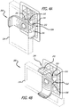
- FIGS. 4A and 4B illustrate an adjustable portable device holder 200 attached to a device 214 and a mounting surface 216 according to one embodiment.
- the device 214 is a smart phone and the mounting surface 216 is an automobile air conditioner vent blade.
- adjustable portable devices can also fit into the adjustable clamping element including, but not limited to a tablet, an e-reader, a powerbank, a speaker, a multimedia player, a flashlight or other light, a television or other display, a laser or radar detector, an air freshener, a fan, a beverage or other device.
- the adjustable portable device holder 200 can also be mounted to other mounting surfaces including, but not limited to an automobile dashboard, an automobile sun visor, a credit card, the brim of a hat, a counter, a tripod, a bicycle, a backpack, a utensil, a ledge or other surface.
- the adjustable portable device holder 200 includes an adjustable clamping element 202 attached to a rotatable mounting element 204.
- the adjustable clamping element 202 can be expanded and retracted to attach different size smartphones to the adjustable portable device holder 200.
- a force can be applied to expand or bias the adjustable clamping element 202 into an activated state and the force can be released to retract the adjustable clamping element 202 into a deactivated state to clamp around the smartphone 214.
- An elastic retracting or biasing element (not shown), such as a compression or torsion spring can be incorporated into the adjustable clamping element 202 to facilitate the expansion and retraction of the adjustable clamping element 202 and to accommodate different size smartphones.
- the adjustable clamping element 202 can also include a gripping material on a surface of the adjustable clamping element 202 to provide a better grip, a better viewing angle or better attachment to the smart phone 214 or other device secured within the adjustable clamping element 202.
- the gripping material can be applied to a portion of the adjustable clamping element 202 or the entire adjustable clamping element 202 can be made of the gripping material.
- the gripping material can be any material that increases the adhesion, grip or coefficient of friction between the gripping surface of the adjustable clamping element 202 and a surface of a device secured within the adjustable clamping element 202.
- the gripping material can include, but is not limited to rubber, polymeric material or other plastic, metal, alloy, fabric, composite material or other material capable of increasing the adhesion, grip or coefficient of friction between the gripping surface of the adjustable clamping element 202 and a surface of a device secured within the adjustable clamping element 202.
- the gripping material and gripping surface can be textured and composed of the same or different material.
- the rotatable mounting element 204 can be directly or indirectly attached to the adjustable clamping element 202.
- the adjustable clamping element 202 and the rotatable mounting element 204 can be one integral part or component parts that are attached together by any attaching means, such as a screw, ratchet, pin, rod or friction or other device that allows the rotatable mounting element 204 to rotate.
- the rotatable mounting element 204 includes a base plate 206 and a plurality of mounting arms 208 extending from the base plate 206.
- the base plate 206 and the plurality of mounting arms 208 can be one integral part or component parts that are attached together by any attaching means.
- the base plate 206 can be a cylindrically shaped disc or other element that is capable of being rotated 360 degrees clockwise or counter-clockwise.
- the base plate 206 provides a rotating platform from which the mounting arms 208 extend.
- the mounting arms 208 are spaced a specified distance apart relative to one another on the base plate 206.
- the mounting arms 208 also extend from the base plate 206 at a specified angle relative to the base plate 206.
- the size of the mounting arms 208, the distance between the mounting arms 208 and the angle at which the mounting arms 208 extend from the base plate 206 establish and define mounting slots 210, 212 between pairs of mounting arms 208.
- the rotatable mounting element 204 includes four mounting arms 208 and four mounting slots 210, 212.
- the mounting arms 208 and mounting slots 210, 212 can engage and attach to an air conditioner vent blade 216 to mount the adjustable portable device holder 200.
- the adjustable portable device holder 200 is mounted to the air conditioner vent blade 216 by positioning, press fitting or wedging a surface of the air conditioner vent blade 216 within one or more mounting slots 210, 212 to engage two or more mounting arms 208.
- the mounting arms 208 can also include a gripping material on a surface of the mounting arms 208 to provide a better grip, a better viewing angle or better attachment to the air conditioner vent blade 216 secured between mounting arms 208.
- the gripping material can be applied to a portion of mounting arms 208 or the entirety of the mounting arms 208 can be made of the gripping material.
- the gripping material can be any material that increases the adhesion, grip or coefficient of friction between the gripping surface of mounting arms 208 and an air conditioner vent blade 216 secured between the mounting arms 208.
- the gripping material can include, but is not limited to rubber, polymeric material or other plastic, metal, alloy, fabric, composite material or other material capable of increasing the adhesion, grip or coefficient of friction between the gripping surface of mounting arms 208 and the air conditioner vent blade 216 secured between the mounting arms 208.
- the gripping material can be and gripping surface and composed of the same or different material.
- the rotatable mounting element 204 includes two different sizes of mounting slots 210, 212 to accommodate different size air conditioner vent blades 216 or other mounting surfaces.
- Two mounting slots 210 having clearance A are larger than the other two mounting slots 212 having clearance B .
- the rotatable mounting element 204 can be rotated to position the mounting arms 208 and mounting slots 210, 212 in a horizontal, vertical, diagonal, circular, concave, convex or any plane between vertical and horizontal planes to engage air conditioner vent blades 216 oriented in a horizontal, vertical, diagonal, circular, concave, convex or any plane between vertical and horizontal planes.
- the mounting arms 208 and mounting slots 210, 212 can be positioned to attach to an air conditioner vent blade in any engagement plane within the 360 degree rotation of the mounting element 204.
- the rotatable mounting element 204 can be rotated to position the larger mounting slots 210 with clearance A in a horizontal, vertical, diagonal, circular, concave, convex or any plane between vertical and horizontal planes to engage or attach to larger air conditioner vent blades 216 oriented in a horizontal, vertical, diagonal, circular, concave, convex or any plane between vertical and horizontal planes.
- the rotatable mounting element 204 can also be rotated to position the smaller mounting slots 212 with clearance B in a horizontal, vertical, diagonal, circular, concave, convex or any plane between vertical and horizontal planes to engage or attach to smaller air conditioner vent blades 216 oriented in a horizontal, vertical, diagonal, circular, concave, convex or any plane between vertical and horizontal planes.
- the rotatable mounting element 204 is capable of being rotated 360 degrees clockwise or counter-clockwise to engage different size mounting surfaces in a horizontal, vertical, diagonal, circular, concave, convex or any plane between vertical and horizontal planes relative to the force of gravity.
- the smart phone 214 attached to the adjustable portable device holder 200 can be rotated into a portrait orientation (shown in FIG. 4A ) and a landscape orientation (shown in FIG. 4B ) by rotating the rotatable mounting element 204.
- the smart phone 214 attached to the adjustable portable device holder 200 can be rotated 360 degrees clockwise or counter-clockwise while it is attached to the adjustable portable device holder 200 by rotating the smart phone 214 and adjustable clamping element 202, while the rotatable mounting element 204 is secured to a mounting surface.
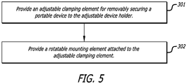
- FIG. 5 illustrates a flow chart of a process for manufacturing an exemplary adjustable portable device holder according to one embodiment.
- the process includes providing an adjustable clamping element for removably securing a portable device to the adjustable portable device holder.
- the adjustable clamping element is capable of being biased into an activated state and unbiased into a deactivated state to secure one of a plurality of different size portable device to the adjustable portable device holder.
- two stainless steel rods can be inserted into an expandable arm cavity of a double injection mold.
- PC/ABS is injected into the cavities of the mold to hold the rods in place and to produce an expandable arm, main body and cover of an adjustable clamping element.
- the mold is then rotated and injected with TPE to form side grips of the expandable arm and body of the adjustable clamping element.
- a stainless steel spring is inserted over each rod and held in place by a stainless steel screw affixed to the end of the rods. Grease is added to the lower portion of the spring and rods (near the screw head).
- the expandable arm is inserted into the body and the springs are lowered and held in place within the body of the adjustable clamping element.
- the cover is the slid on to the body to hold the adjustable arm in place.
- the adjustable clamping element or a surface thereof can also be formed from rubber, polymeric material or other plastic, metal, alloy, or composite material that is rigid, semi-rigid or textured.
- a rotatable mounting element which can be attached to the adjustable clamping element via screw, ratchet, pin, rod or friction or other attachment means.
- the rotatable mounting element includes a plurality of mounting arms each spaced a specified distance apart from one another and extending at a specified angle from a bottom surface of the rotatable mounting element. Each pair of the plurality of mounting arms form a mounting slot therein between.
- the rotatable mounting element is capable of being rotated to position a first mounting slot in a vertical, horizontal or diagonal orientation and a second mounting slot in a vertical, horizontal or diagonal orientation to engage a first mounting surface in a vertical, horizontal or diagonal orientation or a second mounting surface in a vertical, horizontal or diagonal orientation.
- a rotatable mounting element can be formed in whole or part from stainless metal or other metal, alloy or plastic sheet stamped to form a clip or base plate with four arms extending from the base plate, spaced a specified distance apart and bent to a desired angle. If metal or other heat treatable material, the rotatable mounting element can be heat treated to form a rigid structure.
- the rotatable mounting element or a surface thereof can also be formed from rubber, polymeric material or other plastic, metal, alloy, or composite material that is rigid, semi-rigid or textured.
- a zinc-alloy nut or other alloy or material can be formed using a die-cast mold to attach the rotatable mounting element to the adjustable clamping element. Glue is added to the cavity of the nut. The rotatable mounting element is affixed to the main body of the adjustable clamping element via the nut and a second stainless screw. A force gage is used to monitor the rotational force of the rotatable mounting element and the rotatable mounting element is adjusted if screw is too tight or loose.
- TPE is injected into a mold to create a skirt and four socks.
- the skirt and four socks can also be formed from rubber, polymeric material or other plastic, metal, alloy, or composite material that is rigid, semi-rigid or textured.
- the skirt is assembled over the mounting arms of the rotatable mounting element. Glue is added to each mounting arm of the rotatable mounting element. A sock is inserted over each mounting arm, which holds the skirt in place.
Landscapes
- Engineering & Computer Science (AREA)
- Mechanical Engineering (AREA)
- Signal Processing (AREA)
- General Engineering & Computer Science (AREA)
- Telephone Set Structure (AREA)
- Pivots And Pivotal Connections (AREA)
- Clamps And Clips (AREA)
- Fittings On The Vehicle Exterior For Carrying Loads, And Devices For Holding Or Mounting Articles (AREA)
- Casings For Electric Apparatus (AREA)
- Connection Of Plates (AREA)
Claims (15)
- Ein verstellbarer tragbarer Gerätehalter (100, 200), bestehend aus:einem verstellbaren Spannelement (102, 202), das aus- und einfahrbar ist, um tragbare elektronische Geräte unterschiedlicher Größe am verstellbaren tragbaren Gerätehalter (100, 200) zu befestigen;dem verstellbaren Spannelement einschließlich einer Druck- oder Torsionsfeder, die das Aus- und Einfahren des verstellbaren Spannelementes (102, 202) bei Aufbringen oder Lösen einer Kraft auf eine Fläche des verstellbaren Spannelementes (102, 202) erleichtert;einem drehbaren Befestigungselement (104, 204), das an dem verstellbaren Spannelement befestigt ist, (102, 202), dadurch gekennzeichnet, dass;das drehbare Befestigungselement (104, 204) eine Grundplatte (106, 206) umfasst und eine Vielzahl von Befestigungsarmen (108, 208), die von der Grundplatte (106, 206) ausgehen;die Grundplatte (106, 206) eine drehbare Plattform bietet, von der aus die Befestigungsarme (106, 208) ausgehen;die Befestigungsarme (108, 208) in einem Abstand zueinander angeordnet sind und von der Grundplatte (106, 206) in einem Winkel relativ zur Grundplatte (106, 206) ausgehen und einen Befestigungsschlitz (110, 112, 210, 212) zwischen den Befestigungsarmen (108, 208) definieren;der Befestigungsschlitz (110, 112, 210, 212) zwischen den Befestigungsarmen (108, 208) ist so gestaltet, dass er in ein Entlüftungsblatt der Klimaanlage eines Kraftfahrzeugs passt und dort befestigt wird, um den verstellbaren tragbaren Gerätehalter (100, 200) zu montieren; unddie Befestigungsarme des drehbaren Befestigungselements (104, 204) Greifmaterial auf einer Greiffläche der Befestigungsarme aufweisen, um eine Haftung, einen Griff oder einen Reibungskoeffizienten zwischen der Greiffläche der Befestigungsarme (108, 208) und einem Lüftungsflügel der Fahrzeugklimaanlage zu erhöhen, der im Montageschlitz (110, 112, 210, 212) zwischen den Befestigungsarmen (108, 208) befestigt ist.
- Der verstellbare tragbare Gerätehalter (100, 200) nach Anspruch 1, wobei das drehbare Befestigungselement (104, 204), das ganz oder teilweise aus einem Metall-, Legierungs- oder Kunststoffblech besteht, die Grundplatte (106, 206) bildet, mit Armen, die von der Grundplatte ausgehen, in einem Abstand voneinander angeordnet und in einem Winkel zur Grundplatte gebogen sind, um die Befestigungsarme (108, 208) zu bilden;
- Der verstellbare tragbare Gerätehalter (100, 200) nach Anspruch 1 oder 2, wobei die Grundplatte (106, 206) eine zylindrisch geformte Scheibe oder ein anderes Element aufweist, das im oder gegen den Uhrzeigersinn gedreht werden kann; und ferner eine Schraube, eine Sperrvorrichtung, einen Stift oder eine Stange aufweist, die das drehbare Befestigungselement (104, 204) am verstellbaren Klemmelement (102, 202) befestigt und das Drehen des drehbaren Befestigungselements (104, 204) ermöglicht.
- Der verstellbare tragbare Gerätehalter (100, 200) aus Anspruch 1 oder 2, wobei spritzgegossene Socken über die Befestigungsarme (108, 208) des drehbaren Befestigungselements (104, 204) gesteckt werden.
- Der verstellbare tragbare Gerätehalter (100, 200) nach Anspruch 1 oder 2, wobei über den Befestigungsarmen (108, 208) des drehbaren Befestigungselements (104, 204) eine spritzgegossene Schürze montiert ist und spritzgegossene Socken über die Befestigungsarme gesteckt werden und die Schürze an ihrem Platz halten.
- Der verstellbare tragbare Gerätehalter (100, 200) nach Anspruch 1 oder 2, wobei das drehbare Befestigungselement (104, 204) einem tragbaren elektronischen Gerät, das innerhalb des verstellbaren Klemmelements (102, 202) befestigt ist, ermöglicht, im Uhrzeigersinn oder gegen den Uhrzeigersinn in eine Hoch- und eine Querrichtung gedreht zu werden, während das drehbare Befestigungselement (104), 204) an einem Lüftungsflügel einer Fahrzeugklimaanlage befestigt ist.
- Der verstellbare tragbare Gerätehalter (100, 200) nach Anspruch 1 oder 2, wobei die Befestigungsarme (108, 208) mehrere Befestigungsschlitze (110, 112, 210, 212) festlegen, die einen ersten Befestigungsschlitz (110, 210) mit einem ersten Freiraum und einen zweiten Befestigungsschlitz (112, 212) mit einem zweiten Freiraum umfassen, wobei der erste Freiraum größer ist als der zweite Freiraum.
- Der einstellbare tragbare Gerätehalter (100, 200) nach Anspruch 7, wobei das drehbare Befestigungselement (104, 204) gedreht werden kann, um den ersten Befestigungsschlitz (110, 210) mit dem ersten Freiraum in einer horizontalen, vertikalen oder diagonalen Ebene zu positionieren, zur Befestigung des ersten Montageschlitzes (110, 210) an größeren Lüftungslamellen von Fahrzeugklimaanlagen in einer horizontalen, vertikalen oder diagonalen Ebene; und
das drehbare Befestigungselement (104, 204) gedreht werden kann, um den zweiten Befestigungsschlitz (112, 212) mit dem zweiten Freiraum in einer horizontalen, vertikalen oder diagonalen Ebene zu positionieren zwecks Befestigung des zweiten Montageschlitzes (112, 212) an kleineren, horizontal, vertikal oder diagonal ausgerichteten Lüftungslamellen von Fahrzeugklimaanlagen. - Der verstellbare tragbare Gerätehalter (100, 200) nach Anspruch 1 oder 2, wobei das griffige Material aus einem Gummi, Polymermaterial oder anderem Kunststoff-, Metall-, Legierungs-, Gewebe-, Verbundwerkstoff besteht, der die Haftung, den Griff oder den Reibungskoeffizienten zwischen der Grifffläche der Befestigungsarme (108, 208) und einem zwischen den Befestigungsarmen (108, 208) befestigten Lüftungsflügel einer Kraftfahrzeugklimaanlage erhöht.
- Der verstellbare tragbare Gerätehalter (100, 200) nach Anspruch 1 oder 2, wobei:das einstellbare Klemmelement (102, 202) ein griffiges Material auf einer Oberfläche des einstellbaren Klemmelements (102, 202) aufweist, um eine Haftung, einen Griff oder einen Reibungskoeffizienten zwischen der Greifoberfläche des einstellbaren Klemmelements und einer Oberfläche einer tragbaren elektronischen Vorrichtung zu erhöhen, die innerhalb des einstellbaren Klemmelements (102, 202) befestigt ist; unddas griffige Material auf der Oberfläche des verstellbaren Spannelementes (102, 202) ein Gummi, Polymermaterial oder ein anderes Kunststoff-, Metall-, Legierung-, Gewebe- oder Verbundmaterial umfasst, das die Haftung, den Griff oder den Reibungskoeffizienten zwischen der Grifffläche der Befestigungsarme (108, 208) und einem zwischen den Befestigungsarmen (108, 208) befestigten Lüftungsflügel einer Kraftfahrzeugklimaanlage erhöht.
- Der verstellbare tragbare Gerätehalter (100, 200) nach Anspruch 1 oder 2, wobei die Grundplatte (106, 206) des drehbaren Befestigungselements (104, 204) an einem Hauptkörper des verstellbaren Klemmelements (102, 202) befestigt ist;
wenn das verstellbare Klemmelement (102, 202) vollständig eingefahren ist, ist ein Teil des verstellbaren Klemmelements (102, 202), von dem sich ein Seitengriff erstreckt, mit einem Seitenteil des Hauptkörpers bündig; und
wenn das verstellbare Spannelement (102, 202) ausgefahren wird, ist der Teil des verstellbaren Spannelementes, aus dem der Seitengriff herausragt, nicht mehr mit dem Seitenteil des Hauptkörpers bündig. - Der verstellbare tragbare Gerätehalter (100, 200) nach Anspruch 11, wobei der Teil des verstellbaren Klemmelements, von dem der Seitengriff ausgeht, einen ausfahrbaren Arm aufweist.
- Der verstellbare tragbare Gerätehalter (100, 200) nach Anspruch 12, weiter bestehend aus zwei Stangen, die in den ausfahrbaren Arm eingesetzt sind.
- Der verstellbare tragbare Gerätehalter (100, 200) nach Anspruch 13, wobei:wenn das verstellbare Spannelement (102, 202) vollständig eingefahren ist, sind die Stangen nicht freiliegend und damit nicht sichtbar; undwenn das verstellbare Spannelement (102, 202) ausgefahren ist, gibt es einen Spalt zwischen dem Hauptkörper und dem verstellbaren Arm des verstellbaren Spannelementes, wobei die Stangen frei liegen und somit im Spalt sichtbar sind.
- Der verstellbare tragbare Gerätehalter (100, 200) nach Anspruch 1,
wobei das verstellbare Klemmelement (102, 202) so konfiguriert ist, dass es nur an zwei von vier peripheren Seiten eines tragbaren elektronischen Geräts ansetzt, das innerhalb des verstellbaren Klemmelements (102, 202) befestigt ist; und
wobei zu den tragbaren elektronischen Geräten unterschiedlicher Größe, die innerhalb des verstellbaren Klemmelements (102, 202) des verstellbaren Gerätehalters (100, 200) befestigt werden können, auch Smartphones unterschiedlicher Größe gehören.
Applications Claiming Priority (2)
| Application Number | Priority Date | Filing Date | Title |
|---|---|---|---|
| US13/897,062 US9080714B2 (en) | 2012-11-20 | 2013-05-17 | Adjustable portable device holder |
| EP14798238.3A EP2997438B1 (de) | 2013-05-17 | 2014-05-15 | Einstellbare halterung für tragbare vorrichtung |
Related Parent Applications (1)
| Application Number | Title | Priority Date | Filing Date |
|---|---|---|---|
| EP14798238.3A Division EP2997438B1 (de) | 2013-05-17 | 2014-05-15 | Einstellbare halterung für tragbare vorrichtung |
Publications (2)
| Publication Number | Publication Date |
|---|---|
| EP3244283A1 EP3244283A1 (de) | 2017-11-15 |
| EP3244283B1 true EP3244283B1 (de) | 2018-06-27 |
Family
ID=51898882
Family Applications (2)
| Application Number | Title | Priority Date | Filing Date |
|---|---|---|---|
| EP17178044.8A Not-in-force EP3244283B1 (de) | 2013-05-17 | 2014-05-15 | Einstellbare halterung für tragbare vorrichtung |
| EP14798238.3A Active EP2997438B1 (de) | 2013-05-17 | 2014-05-15 | Einstellbare halterung für tragbare vorrichtung |
Family Applications After (1)
| Application Number | Title | Priority Date | Filing Date |
|---|---|---|---|
| EP14798238.3A Active EP2997438B1 (de) | 2013-05-17 | 2014-05-15 | Einstellbare halterung für tragbare vorrichtung |
Country Status (16)
| Country | Link |
|---|---|
| EP (2) | EP3244283B1 (de) |
| JP (1) | JP5976238B2 (de) |
| KR (1) | KR101660669B1 (de) |
| CN (2) | CN105229557B (de) |
| AU (1) | AU2014265355B2 (de) |
| BR (1) | BR112015018915A8 (de) |
| CA (1) | CA2903424C (de) |
| DK (1) | DK2997438T3 (de) |
| ES (2) | ES2685771T3 (de) |
| HU (1) | HUE033691T2 (de) |
| IL (1) | IL240308A0 (de) |
| MX (1) | MX346357B (de) |
| PL (1) | PL2997438T3 (de) |
| PT (1) | PT2997438T (de) |
| RU (1) | RU2601253C1 (de) |
| WO (1) | WO2014186609A1 (de) |
Families Citing this family (17)
| Publication number | Priority date | Publication date | Assignee | Title |
|---|---|---|---|---|
| CN107404555A (zh) * | 2016-05-21 | 2017-11-28 | 麦广树 | 具有宽度自适应机构的手机架 |
| CN105978675B (zh) * | 2016-06-24 | 2019-01-08 | 西安电子科技大学 | 基于正交频分多址上行接入方法 |
| CN106051393A (zh) * | 2016-07-11 | 2016-10-26 | 深圳天珑无线科技有限公司 | 柔性显示器及其支架 |
| KR101934023B1 (ko) * | 2016-08-29 | 2019-01-16 | 김세한 | 휴대용 단말기 거치 장치 |
| CN106231029A (zh) * | 2016-08-31 | 2016-12-14 | 深圳多哚新技术有限责任公司 | 一种虚拟现实设备 |
| US11097665B2 (en) | 2017-06-01 | 2021-08-24 | Pioneer Corporation | Holding mechanism and holding device |
| KR200489241Y1 (ko) * | 2017-12-20 | 2019-05-21 | (주)가나웨이브시스 | 차량용 거치대 |
| CN108061220B (zh) * | 2017-12-22 | 2019-09-24 | 山东广域科技有限责任公司 | 一种电力通信检测维护装置 |
| KR101854099B1 (ko) * | 2018-01-31 | 2018-06-08 | 김재문 | 송풍구 고정형 휴대전화 거치대 |
| US10782803B2 (en) | 2018-02-19 | 2020-09-22 | Dillon Markey | Ergonomic bike grip controller |
| CN109185678A (zh) * | 2018-11-05 | 2019-01-11 | 柳小佳 | 一种移动电子设备固定支架及调整夹持状态的方法 |
| JP7313043B2 (ja) * | 2019-08-05 | 2023-07-24 | 槌屋ヤック株式会社 | 自動車用スマートフォンホルダ |
| CN112550170A (zh) * | 2020-12-02 | 2021-03-26 | 宋福存 | 一种可旋转定位的车载手机支架 |
| KR102291192B1 (ko) * | 2020-12-15 | 2021-08-18 | 김영수 | 디지털 디바이스 거치대 |
| CN113511151A (zh) * | 2021-08-21 | 2021-10-19 | 深圳市福伦达精工技术有限公司 | 汽车智能诊断仪 |
| CN114056241B (zh) * | 2021-11-23 | 2023-08-01 | 浙江极氪智能科技有限公司 | 一种固定件及具有其的手套箱 |
| CN119232864B (zh) * | 2024-09-27 | 2025-05-30 | 宜宾佳信电子科技有限公司 | 一种显示增强的液晶监视器 |
Family Cites Families (33)
| Publication number | Priority date | Publication date | Assignee | Title |
|---|---|---|---|---|
| US5305381A (en) * | 1992-11-09 | 1994-04-19 | Wang Chin Y | Cradle for telephone |
| CN2150682Y (zh) * | 1993-02-22 | 1993-12-22 | 王进杨 | 移动电话夹座 |
| IT1273739B (it) * | 1994-07-29 | 1997-07-09 | Marco Valerio Masi | Supporto facilmente rimovibile per il sostegno di un telefono cellulare all'interno di un veicolo |
| CN2212864Y (zh) * | 1994-09-21 | 1995-11-15 | 怡利电子工业股份有限公司 | 可免持话筒支撑架 |
| US6103201A (en) * | 1995-07-25 | 2000-08-15 | Green; Dennis E. | Propeller air freshener |
| KR20000044438A (ko) * | 1998-12-30 | 2000-07-15 | 윤종용 | 핸즈 프리 킷트용 거치대 |
| ES2161664T3 (es) * | 1999-02-25 | 2007-07-01 | Sara Lee/De N.V. | Un ambientador. |
| US6366672B1 (en) * | 1999-11-10 | 2002-04-02 | Wen-Feng Tsay | Mobile phone holder |
| CN2438620Y (zh) * | 2000-08-17 | 2001-07-11 | 高而富股份有限公司 | 单动式移动电话夹持座 |
| JP4739601B2 (ja) * | 2001-08-17 | 2011-08-03 | 株式会社ナポレックス | 物品ホルダーのエアコン吹き出し口ルーバーへの取付具 |
| US6441872B1 (en) * | 2001-10-15 | 2002-08-27 | Photic Electronics Co., Ltd. | Vehicle reversal monitoring device mounting fixture |
| JP4108987B2 (ja) * | 2002-02-07 | 2008-06-25 | 星光産業株式会社 | 保持具 |
| US7650230B1 (en) * | 2003-03-26 | 2010-01-19 | Garmin Ltd. | Navigational device for mounting on a support pillar of a vehicle and a method for doing same |
| US7080812B2 (en) * | 2004-01-17 | 2006-07-25 | Belkin Corporation | Holding device for holding a portable object, and method of manufacturing same |
| US6988907B2 (en) * | 2004-03-03 | 2006-01-24 | Ta-Shuo Chang | Sectional adapter of clamping holder for automobiles |
| DE202004007340U1 (de) * | 2004-05-07 | 2004-07-22 | Chang, Ta-Shuo | Halteanordnung zum Anbau an ein Lüftergitter |
| US7537190B2 (en) * | 2006-06-13 | 2009-05-26 | Eagle Fan | Holding device for electronic apparatus |
| KR200429528Y1 (ko) * | 2006-08-14 | 2006-10-24 | (주)정인일렉텍 | 방향제가 구비된 휴대폰 거치대 |
| EP1902736A1 (de) * | 2006-09-19 | 2008-03-26 | Sara Lee/DE N.V. | Lufterfrischer zum Verströmen zweier Düfte |
| US20080190978A1 (en) * | 2007-02-14 | 2008-08-14 | Paul Brassard | Mounting apparatus |
| JP2008202771A (ja) * | 2007-02-19 | 2008-09-04 | Napolex Co | 物品ホルダー |
| RU2461474C1 (ru) * | 2008-07-01 | 2012-09-20 | Вольво Ластвагнар Аб | Держатель монитора для транспортного средства |
| DE202008010276U1 (de) * | 2008-07-31 | 2008-11-20 | COMART Corporation, Sindian City | Verstellvorrichtung für Halterung im Fahrzeug |
| CN101674096B (zh) * | 2008-09-12 | 2013-03-13 | 汪玉华 | 手机和蓝牙耳机放置和充电的支架 |
| JP3151546U (ja) * | 2009-04-16 | 2009-06-25 | 株式会社セイワ | 物品ホルダー |
| US8202114B2 (en) * | 2009-12-14 | 2012-06-19 | Mitac International Corp. | Mobile phone cradle with three-point retention of portable electronic device installed in the cradle |
| CN201633647U (zh) * | 2010-01-09 | 2010-11-17 | 励勋儿 | 车用手机座 |
| JP3164223U (ja) * | 2010-09-07 | 2010-11-18 | 株式会社セイワ | 物品ホルダー |
| US8235334B1 (en) * | 2011-02-16 | 2012-08-07 | Mark Kobal | Tablet computer holder and support |
| KR20120125933A (ko) * | 2011-05-09 | 2012-11-19 | 오치완 | 휴대폰 거치대를 구비한 차량용 방향제/재떨이 |
| US20130037590A1 (en) * | 2011-08-12 | 2013-02-14 | Namsung Co., Ltd. | Holder apparatus for mounting a media device in a vehicle |
| US9103487B2 (en) * | 2012-03-24 | 2015-08-11 | Daymen Us, Inc. | Adjustable mounting clip and system using same |
| CN202907016U (zh) * | 2012-09-26 | 2013-04-24 | 毛亚丽 | 一种手机底座 |
-
2014
- 2014-05-15 EP EP17178044.8A patent/EP3244283B1/de not_active Not-in-force
- 2014-05-15 CN CN201480019028.8A patent/CN105229557B/zh active Active
- 2014-05-15 DK DK14798238.3T patent/DK2997438T3/en active
- 2014-05-15 BR BR112015018915A patent/BR112015018915A8/pt not_active Application Discontinuation
- 2014-05-15 RU RU2015137589/28A patent/RU2601253C1/ru not_active IP Right Cessation
- 2014-05-15 PT PT147982383T patent/PT2997438T/pt unknown
- 2014-05-15 ES ES17178044.8T patent/ES2685771T3/es active Active
- 2014-05-15 KR KR1020157035564A patent/KR101660669B1/ko not_active Expired - Fee Related
- 2014-05-15 PL PL14798238T patent/PL2997438T3/pl unknown
- 2014-05-15 CN CN201710153065.3A patent/CN107415844A/zh active Pending
- 2014-05-15 WO PCT/US2014/038253 patent/WO2014186609A1/en not_active Ceased
- 2014-05-15 MX MX2015015365A patent/MX346357B/es active IP Right Grant
- 2014-05-15 CA CA2903424A patent/CA2903424C/en not_active Expired - Fee Related
- 2014-05-15 JP JP2015557246A patent/JP5976238B2/ja not_active Expired - Fee Related
- 2014-05-15 EP EP14798238.3A patent/EP2997438B1/de active Active
- 2014-05-15 AU AU2014265355A patent/AU2014265355B2/en not_active Ceased
- 2014-05-15 HU HUE14798238A patent/HUE033691T2/en unknown
- 2014-05-15 ES ES14798238.3T patent/ES2639497T3/es active Active
-
2015
- 2015-08-02 IL IL240308A patent/IL240308A0/en not_active IP Right Cessation
Non-Patent Citations (1)
| Title |
|---|
| None * |
Also Published As
| Publication number | Publication date |
|---|---|
| WO2014186609A1 (en) | 2014-11-20 |
| HUE033691T2 (en) | 2017-12-28 |
| AU2014265355B2 (en) | 2015-10-01 |
| HK1217552A1 (en) | 2017-01-13 |
| AU2014265355A1 (en) | 2015-09-17 |
| JP2016513218A (ja) | 2016-05-12 |
| CA2903424A1 (en) | 2014-11-20 |
| MX2015015365A (es) | 2016-03-04 |
| MX346357B (es) | 2017-03-15 |
| EP3244283A1 (de) | 2017-11-15 |
| CA2903424C (en) | 2016-04-26 |
| CN105229557B (zh) | 2017-04-05 |
| KR101660669B1 (ko) | 2016-09-27 |
| DK2997438T3 (en) | 2017-09-11 |
| IL240308A (en) | 2015-10-29 |
| CN105229557A (zh) | 2016-01-06 |
| CN107415844A (zh) | 2017-12-01 |
| EP2997438B1 (de) | 2017-06-28 |
| BR112015018915A8 (pt) | 2019-11-05 |
| RU2601253C1 (ru) | 2016-10-27 |
| EP2997438A4 (de) | 2016-05-04 |
| EP2997438A1 (de) | 2016-03-23 |
| PL2997438T3 (pl) | 2017-12-29 |
| JP5976238B2 (ja) | 2016-08-24 |
| BR112015018915A2 (pt) | 2017-07-18 |
| ES2639497T3 (es) | 2017-10-26 |
| IL240308A0 (en) | 2015-10-29 |
| ES2685771T3 (es) | 2018-10-11 |
| PT2997438T (pt) | 2017-09-13 |
| KR20160005126A (ko) | 2016-01-13 |
Similar Documents
| Publication | Publication Date | Title |
|---|---|---|
| US10315585B2 (en) | Adjustable portable device holder | |
| EP3244283B1 (de) | Einstellbare halterung für tragbare vorrichtung | |
| US20180043840A1 (en) | Portable device holder | |
| US20170314732A1 (en) | Apparatuses that provide a mount and a stand for portable electronic devices | |
| US20170072872A1 (en) | Adjustable Vent Clip And Gripping Clamp System | |
| US9445512B2 (en) | Holder having adjustable clamping orientation | |
| CN206246957U (zh) | 一种网络摄像头多方位调节支架 | |
| US20200361396A1 (en) | Adjustable removable device caddy | |
| HK1217552B (en) | Adjustable portable device holder | |
| CN202163367U (zh) | 车载头颈支架 | |
| KR20130071039A (ko) | 전자기기를 차량 내부에 위치시키는 거치대 | |
| CN205554071U (zh) | 一种车载手机架 | |
| CN204161243U (zh) | 车载平板电子设备支架 | |
| CN204741499U (zh) | 一种可以安装于多种物体上的多功能摄像头 | |
| CN213879906U (zh) | 一种车载手机支架 | |
| CN215398440U (zh) | 一种汽车后视镜的盲区观察装置 | |
| US20130250494A1 (en) | Electronic device supporter |
Legal Events
| Date | Code | Title | Description |
|---|---|---|---|
| PUAI | Public reference made under article 153(3) epc to a published international application that has entered the european phase |
Free format text: ORIGINAL CODE: 0009012 |
|
| STAA | Information on the status of an ep patent application or granted ep patent |
Free format text: STATUS: REQUEST FOR EXAMINATION WAS MADE |
|
| 17P | Request for examination filed |
Effective date: 20170627 |
|
| AC | Divisional application: reference to earlier application |
Ref document number: 2997438 Country of ref document: EP Kind code of ref document: P |
|
| AK | Designated contracting states |
Kind code of ref document: A1 Designated state(s): AL AT BE BG CH CY CZ DE DK EE ES FI FR GB GR HR HU IE IS IT LI LT LU LV MC MK MT NL NO PL PT RO RS SE SI SK SM TR |
|
| GRAP | Despatch of communication of intention to grant a patent |
Free format text: ORIGINAL CODE: EPIDOSNIGR1 |
|
| STAA | Information on the status of an ep patent application or granted ep patent |
Free format text: STATUS: GRANT OF PATENT IS INTENDED |
|
| INTG | Intention to grant announced |
Effective date: 20180403 |
|
| GRAS | Grant fee paid |
Free format text: ORIGINAL CODE: EPIDOSNIGR3 |
|
| GRAA | (expected) grant |
Free format text: ORIGINAL CODE: 0009210 |
|
| STAA | Information on the status of an ep patent application or granted ep patent |
Free format text: STATUS: THE PATENT HAS BEEN GRANTED |
|
| AC | Divisional application: reference to earlier application |
Ref document number: 2997438 Country of ref document: EP Kind code of ref document: P |
|
| AK | Designated contracting states |
Kind code of ref document: B1 Designated state(s): AL AT BE BG CH CY CZ DE DK EE ES FI FR GB GR HR HU IE IS IT LI LT LU LV MC MK MT NL NO PL PT RO RS SE SI SK SM TR |
|
| REG | Reference to a national code |
Ref country code: GB Ref legal event code: FG4D |
|
| REG | Reference to a national code |
Ref country code: AT Ref legal event code: REF Ref document number: 1012869 Country of ref document: AT Kind code of ref document: T Effective date: 20180715 |
|
| REG | Reference to a national code |
Ref country code: IE Ref legal event code: FG4D |
|
| REG | Reference to a national code |
Ref country code: DE Ref legal event code: R096 Ref document number: 602014027730 Country of ref document: DE |
|
| REG | Reference to a national code |
Ref country code: ES Ref legal event code: FG2A Ref document number: 2685771 Country of ref document: ES Kind code of ref document: T3 Effective date: 20181011 |
|
| PG25 | Lapsed in a contracting state [announced via postgrant information from national office to epo] |
Ref country code: FI Free format text: LAPSE BECAUSE OF FAILURE TO SUBMIT A TRANSLATION OF THE DESCRIPTION OR TO PAY THE FEE WITHIN THE PRESCRIBED TIME-LIMIT Effective date: 20180627 Ref country code: BG Free format text: LAPSE BECAUSE OF FAILURE TO SUBMIT A TRANSLATION OF THE DESCRIPTION OR TO PAY THE FEE WITHIN THE PRESCRIBED TIME-LIMIT Effective date: 20180927 Ref country code: SE Free format text: LAPSE BECAUSE OF FAILURE TO SUBMIT A TRANSLATION OF THE DESCRIPTION OR TO PAY THE FEE WITHIN THE PRESCRIBED TIME-LIMIT Effective date: 20180627 Ref country code: NO Free format text: LAPSE BECAUSE OF FAILURE TO SUBMIT A TRANSLATION OF THE DESCRIPTION OR TO PAY THE FEE WITHIN THE PRESCRIBED TIME-LIMIT Effective date: 20180927 Ref country code: LT Free format text: LAPSE BECAUSE OF FAILURE TO SUBMIT A TRANSLATION OF THE DESCRIPTION OR TO PAY THE FEE WITHIN THE PRESCRIBED TIME-LIMIT Effective date: 20180627 |
|
| REG | Reference to a national code |
Ref country code: NL Ref legal event code: MP Effective date: 20180627 |
|
| REG | Reference to a national code |
Ref country code: LT Ref legal event code: MG4D |
|
| PG25 | Lapsed in a contracting state [announced via postgrant information from national office to epo] |
Ref country code: GR Free format text: LAPSE BECAUSE OF FAILURE TO SUBMIT A TRANSLATION OF THE DESCRIPTION OR TO PAY THE FEE WITHIN THE PRESCRIBED TIME-LIMIT Effective date: 20180928 Ref country code: HR Free format text: LAPSE BECAUSE OF FAILURE TO SUBMIT A TRANSLATION OF THE DESCRIPTION OR TO PAY THE FEE WITHIN THE PRESCRIBED TIME-LIMIT Effective date: 20180627 Ref country code: RS Free format text: LAPSE BECAUSE OF FAILURE TO SUBMIT A TRANSLATION OF THE DESCRIPTION OR TO PAY THE FEE WITHIN THE PRESCRIBED TIME-LIMIT Effective date: 20180627 Ref country code: LV Free format text: LAPSE BECAUSE OF FAILURE TO SUBMIT A TRANSLATION OF THE DESCRIPTION OR TO PAY THE FEE WITHIN THE PRESCRIBED TIME-LIMIT Effective date: 20180627 |
|
| REG | Reference to a national code |
Ref country code: AT Ref legal event code: MK05 Ref document number: 1012869 Country of ref document: AT Kind code of ref document: T Effective date: 20180627 |
|
| PG25 | Lapsed in a contracting state [announced via postgrant information from national office to epo] |
Ref country code: NL Free format text: LAPSE BECAUSE OF FAILURE TO SUBMIT A TRANSLATION OF THE DESCRIPTION OR TO PAY THE FEE WITHIN THE PRESCRIBED TIME-LIMIT Effective date: 20180627 |
|
| PG25 | Lapsed in a contracting state [announced via postgrant information from national office to epo] |
Ref country code: CZ Free format text: LAPSE BECAUSE OF FAILURE TO SUBMIT A TRANSLATION OF THE DESCRIPTION OR TO PAY THE FEE WITHIN THE PRESCRIBED TIME-LIMIT Effective date: 20180627 Ref country code: PL Free format text: LAPSE BECAUSE OF FAILURE TO SUBMIT A TRANSLATION OF THE DESCRIPTION OR TO PAY THE FEE WITHIN THE PRESCRIBED TIME-LIMIT Effective date: 20180627 Ref country code: EE Free format text: LAPSE BECAUSE OF FAILURE TO SUBMIT A TRANSLATION OF THE DESCRIPTION OR TO PAY THE FEE WITHIN THE PRESCRIBED TIME-LIMIT Effective date: 20180627 Ref country code: AT Free format text: LAPSE BECAUSE OF FAILURE TO SUBMIT A TRANSLATION OF THE DESCRIPTION OR TO PAY THE FEE WITHIN THE PRESCRIBED TIME-LIMIT Effective date: 20180627 Ref country code: IS Free format text: LAPSE BECAUSE OF FAILURE TO SUBMIT A TRANSLATION OF THE DESCRIPTION OR TO PAY THE FEE WITHIN THE PRESCRIBED TIME-LIMIT Effective date: 20181027 Ref country code: RO Free format text: LAPSE BECAUSE OF FAILURE TO SUBMIT A TRANSLATION OF THE DESCRIPTION OR TO PAY THE FEE WITHIN THE PRESCRIBED TIME-LIMIT Effective date: 20180627 Ref country code: SK Free format text: LAPSE BECAUSE OF FAILURE TO SUBMIT A TRANSLATION OF THE DESCRIPTION OR TO PAY THE FEE WITHIN THE PRESCRIBED TIME-LIMIT Effective date: 20180627 |
|
| PG25 | Lapsed in a contracting state [announced via postgrant information from national office to epo] |
Ref country code: SM Free format text: LAPSE BECAUSE OF FAILURE TO SUBMIT A TRANSLATION OF THE DESCRIPTION OR TO PAY THE FEE WITHIN THE PRESCRIBED TIME-LIMIT Effective date: 20180627 |
|
| REG | Reference to a national code |
Ref country code: DE Ref legal event code: R097 Ref document number: 602014027730 Country of ref document: DE |
|
| PLBE | No opposition filed within time limit |
Free format text: ORIGINAL CODE: 0009261 |
|
| STAA | Information on the status of an ep patent application or granted ep patent |
Free format text: STATUS: NO OPPOSITION FILED WITHIN TIME LIMIT |
|
| PG25 | Lapsed in a contracting state [announced via postgrant information from national office to epo] |
Ref country code: DK Free format text: LAPSE BECAUSE OF FAILURE TO SUBMIT A TRANSLATION OF THE DESCRIPTION OR TO PAY THE FEE WITHIN THE PRESCRIBED TIME-LIMIT Effective date: 20180627 |
|
| 26N | No opposition filed |
Effective date: 20190328 |
|
| PGFP | Annual fee paid to national office [announced via postgrant information from national office to epo] |
Ref country code: IT Payment date: 20190510 Year of fee payment: 6 Ref country code: ES Payment date: 20190604 Year of fee payment: 6 |
|
| PG25 | Lapsed in a contracting state [announced via postgrant information from national office to epo] |
Ref country code: SI Free format text: LAPSE BECAUSE OF FAILURE TO SUBMIT A TRANSLATION OF THE DESCRIPTION OR TO PAY THE FEE WITHIN THE PRESCRIBED TIME-LIMIT Effective date: 20180627 |
|
| PGFP | Annual fee paid to national office [announced via postgrant information from national office to epo] |
Ref country code: FR Payment date: 20190429 Year of fee payment: 6 |
|
| PGFP | Annual fee paid to national office [announced via postgrant information from national office to epo] |
Ref country code: DE Payment date: 20190624 Year of fee payment: 6 Ref country code: GB Payment date: 20190429 Year of fee payment: 6 |
|
| PG25 | Lapsed in a contracting state [announced via postgrant information from national office to epo] |
Ref country code: AL Free format text: LAPSE BECAUSE OF FAILURE TO SUBMIT A TRANSLATION OF THE DESCRIPTION OR TO PAY THE FEE WITHIN THE PRESCRIBED TIME-LIMIT Effective date: 20180627 |
|
| REG | Reference to a national code |
Ref country code: CH Ref legal event code: PL |
|
| PG25 | Lapsed in a contracting state [announced via postgrant information from national office to epo] |
Ref country code: MC Free format text: LAPSE BECAUSE OF FAILURE TO SUBMIT A TRANSLATION OF THE DESCRIPTION OR TO PAY THE FEE WITHIN THE PRESCRIBED TIME-LIMIT Effective date: 20180627 Ref country code: CH Free format text: LAPSE BECAUSE OF NON-PAYMENT OF DUE FEES Effective date: 20190531 Ref country code: LI Free format text: LAPSE BECAUSE OF NON-PAYMENT OF DUE FEES Effective date: 20190531 |
|
| REG | Reference to a national code |
Ref country code: BE Ref legal event code: MM Effective date: 20190531 |
|
| PG25 | Lapsed in a contracting state [announced via postgrant information from national office to epo] |
Ref country code: LU Free format text: LAPSE BECAUSE OF NON-PAYMENT OF DUE FEES Effective date: 20190515 |
|
| PG25 | Lapsed in a contracting state [announced via postgrant information from national office to epo] |
Ref country code: TR Free format text: LAPSE BECAUSE OF FAILURE TO SUBMIT A TRANSLATION OF THE DESCRIPTION OR TO PAY THE FEE WITHIN THE PRESCRIBED TIME-LIMIT Effective date: 20180627 |
|
| PG25 | Lapsed in a contracting state [announced via postgrant information from national office to epo] |
Ref country code: IE Free format text: LAPSE BECAUSE OF NON-PAYMENT OF DUE FEES Effective date: 20190515 |
|
| PG25 | Lapsed in a contracting state [announced via postgrant information from national office to epo] |
Ref country code: BE Free format text: LAPSE BECAUSE OF NON-PAYMENT OF DUE FEES Effective date: 20190531 |
|
| PG25 | Lapsed in a contracting state [announced via postgrant information from national office to epo] |
Ref country code: PT Free format text: LAPSE BECAUSE OF FAILURE TO SUBMIT A TRANSLATION OF THE DESCRIPTION OR TO PAY THE FEE WITHIN THE PRESCRIBED TIME-LIMIT Effective date: 20181029 |
|
| REG | Reference to a national code |
Ref country code: DE Ref legal event code: R119 Ref document number: 602014027730 Country of ref document: DE |
|
| GBPC | Gb: european patent ceased through non-payment of renewal fee |
Effective date: 20200515 |
|
| PG25 | Lapsed in a contracting state [announced via postgrant information from national office to epo] |
Ref country code: GB Free format text: LAPSE BECAUSE OF NON-PAYMENT OF DUE FEES Effective date: 20200515 Ref country code: FR Free format text: LAPSE BECAUSE OF NON-PAYMENT OF DUE FEES Effective date: 20200531 |
|
| PG25 | Lapsed in a contracting state [announced via postgrant information from national office to epo] |
Ref country code: CY Free format text: LAPSE BECAUSE OF FAILURE TO SUBMIT A TRANSLATION OF THE DESCRIPTION OR TO PAY THE FEE WITHIN THE PRESCRIBED TIME-LIMIT Effective date: 20180627 Ref country code: DE Free format text: LAPSE BECAUSE OF NON-PAYMENT OF DUE FEES Effective date: 20201201 |
|
| PG25 | Lapsed in a contracting state [announced via postgrant information from national office to epo] |
Ref country code: HU Free format text: LAPSE BECAUSE OF FAILURE TO SUBMIT A TRANSLATION OF THE DESCRIPTION OR TO PAY THE FEE WITHIN THE PRESCRIBED TIME-LIMIT; INVALID AB INITIO Effective date: 20140515 Ref country code: MT Free format text: LAPSE BECAUSE OF FAILURE TO SUBMIT A TRANSLATION OF THE DESCRIPTION OR TO PAY THE FEE WITHIN THE PRESCRIBED TIME-LIMIT Effective date: 20180627 |
|
| REG | Reference to a national code |
Ref country code: ES Ref legal event code: FD2A Effective date: 20210929 |
|
| PG25 | Lapsed in a contracting state [announced via postgrant information from national office to epo] |
Ref country code: IT Free format text: LAPSE BECAUSE OF NON-PAYMENT OF DUE FEES Effective date: 20200515 |
|
| PG25 | Lapsed in a contracting state [announced via postgrant information from national office to epo] |
Ref country code: ES Free format text: LAPSE BECAUSE OF NON-PAYMENT OF DUE FEES Effective date: 20200516 |
|
| PG25 | Lapsed in a contracting state [announced via postgrant information from national office to epo] |
Ref country code: MK Free format text: LAPSE BECAUSE OF FAILURE TO SUBMIT A TRANSLATION OF THE DESCRIPTION OR TO PAY THE FEE WITHIN THE PRESCRIBED TIME-LIMIT Effective date: 20180627 |