EP3244205A1 - Unite de raccordement capillaire pour appareils d'analyse et appareils medicaux - Google Patents
Unite de raccordement capillaire pour appareils d'analyse et appareils medicaux Download PDFInfo
- Publication number
- EP3244205A1 EP3244205A1 EP16001083.1A EP16001083A EP3244205A1 EP 3244205 A1 EP3244205 A1 EP 3244205A1 EP 16001083 A EP16001083 A EP 16001083A EP 3244205 A1 EP3244205 A1 EP 3244205A1
- Authority
- EP
- European Patent Office
- Prior art keywords
- capillary
- sealing element
- connection
- sleeve
- sealing
- Prior art date
- Legal status (The legal status is an assumption and is not a legal conclusion. Google has not performed a legal analysis and makes no representation as to the accuracy of the status listed.)
- Withdrawn
Links
Images


Classifications
-
- B—PERFORMING OPERATIONS; TRANSPORTING
- B01—PHYSICAL OR CHEMICAL PROCESSES OR APPARATUS IN GENERAL
- B01L—CHEMICAL OR PHYSICAL LABORATORY APPARATUS FOR GENERAL USE
- B01L3/00—Containers or dishes for laboratory use, e.g. laboratory glassware; Droppers
- B01L3/56—Labware specially adapted for transferring fluids
- B01L3/563—Joints or fittings ; Separable fluid transfer means to transfer fluids between at least two containers, e.g. connectors
-
- F—MECHANICAL ENGINEERING; LIGHTING; HEATING; WEAPONS; BLASTING
- F16—ENGINEERING ELEMENTS AND UNITS; GENERAL MEASURES FOR PRODUCING AND MAINTAINING EFFECTIVE FUNCTIONING OF MACHINES OR INSTALLATIONS; THERMAL INSULATION IN GENERAL
- F16L—PIPES; JOINTS OR FITTINGS FOR PIPES; SUPPORTS FOR PIPES, CABLES OR PROTECTIVE TUBING; MEANS FOR THERMAL INSULATION IN GENERAL
- F16L15/00—Screw-threaded joints; Forms of screw-threads for such joints
- F16L15/04—Screw-threaded joints; Forms of screw-threads for such joints with additional sealings
-
- G—PHYSICS
- G01—MEASURING; TESTING
- G01N—INVESTIGATING OR ANALYSING MATERIALS BY DETERMINING THEIR CHEMICAL OR PHYSICAL PROPERTIES
- G01N30/00—Investigating or analysing materials by separation into components using adsorption, absorption or similar phenomena or using ion-exchange, e.g. chromatography or field flow fractionation
- G01N30/02—Column chromatography
- G01N30/60—Construction of the column
- G01N30/6004—Construction of the column end pieces
- G01N30/6026—Fluid seals
-
- B—PERFORMING OPERATIONS; TRANSPORTING
- B01—PHYSICAL OR CHEMICAL PROCESSES OR APPARATUS IN GENERAL
- B01L—CHEMICAL OR PHYSICAL LABORATORY APPARATUS FOR GENERAL USE
- B01L2200/00—Solutions for specific problems relating to chemical or physical laboratory apparatus
- B01L2200/06—Fluid handling related problems
- B01L2200/0689—Sealing
-
- B—PERFORMING OPERATIONS; TRANSPORTING
- B01—PHYSICAL OR CHEMICAL PROCESSES OR APPARATUS IN GENERAL
- B01L—CHEMICAL OR PHYSICAL LABORATORY APPARATUS FOR GENERAL USE
- B01L2300/00—Additional constructional details
- B01L2300/08—Geometry, shape and general structure
- B01L2300/0832—Geometry, shape and general structure cylindrical, tube shaped
- B01L2300/0838—Capillaries
Definitions
- the invention relates to a capillary connection unit for analyzers and medical devices according to claim 1, comprising a capillary having at least one end portion and a free end thereon, with at least one connection element arranged at the end portion of the capillary, said connection element having an axial passage through which the capillary extends, with a sealing element, which surrounds the capillary at least at its free end and with a metallic sleeve member which at least partially surrounding the sealing element radially outside, and which has a first, the connection element facing the end and a connecting element facing away from the receiving area, wherein the connecting element with the free end of the capillary is adapted to be releasably connected to a counter element and to exert an axial thrust force on the sealing element.
- the invention particularly relates to a capillary connection unit for analysis devices and medical devices with individual features of patent claim 1.
- Capillary ports for analyzers and medical devices typically consist of a plug connection between a capillary connector and a mating member having a receiving space for insertion of one end of the capillary connector.
- the elements are preferably designed as so-called “fittings” which can be screwed together.
- a sealing element is provided which is intended to seal the connection between capillary connection element and counter element or capillary connection plug and mating plug in the region of the opposing capillary openings, even at higher pressures. By screwing capillary connection element and counter element, the sealing element can be pressed with high contact pressure on an opposite wall of the counter element.
- the DE 10 2009 022 368 B3 discloses a plug unit for connecting capillaries, in particular for high performance liquid chromatography, with a plug housing having an axial bore, with a plug capillary, which projects through the axial bore of the plug housing, and with an annular cross-section sealing element, which surrounds the plug capillary and in that the front end of the plug capillary is sealed against the capillary receiving opening of the socket unit by elastic and / or plastic deformation of the sealing element.
- the plug housing is designed so that it can be detachably connected to a socket unit, wherein the front end of the plug capillary in the connected state of plug unit and socket unit protrudes into a capillary receiving opening of the socket unit and with its end face substantially flush a front end of a Buchsenkapillare or a Buchsenkapillarenö réelle the socket unit is opposite.
- the sealing element should be acted upon indirectly or directly with an axial contact pressure.
- the DE 10 2009 022 368 B3 further provides a sleeve formed as a hollow cylindrical pressure piece which engages around the sealing element in an axial region remote from the end face of the plug capillary.
- the pressure piece has one of the end face of the plug capillary remote, rear end side, which is acted upon in the connected state of the plug unit and socket unit from the connector housing with an axial compressive force.
- the pressure piece and the sealing element are fixedly connected to the plug capillary, so that the axial pressure force can be transmitted to the end face of the sealing element without a relative movement between the pressure piece and sealing element on the one hand and the plug capillary on the other.
- the sealing element made of PEEK polyetheretherketone
- the sealing element made of PEEK must be able to expand circumferentially by a few tenths of a millimeter in the sealing area in order to achieve a leak-tightness. Due to the flowability of the PEEK material under pressure, this compound must be tightened regularly, otherwise the circumferential tightness decreases.
- the present invention seeks to provide a Kapillaran gleichiser that allows improved, safe and low-maintenance application and a good seal even in high-pressure applications. Furthermore, it is desirable to avoid the sealing element in dead spaces (tolerance fields the sealing area) as well as a squeezing of the sealing element into the capillary channel or a reduction of the capillary channel to prevent.
- the sleeve element is guided axially displaceably both with respect to the connection element and with respect to the capillary, wherein an inner diameter d iH of the sleeve element in the receiving region facing away from the connection element is at least as large as the outer diameter d aD of the sealing element and wherein the sleeve element is configured to receive the sealing element substantially completely in its receiving area and wherein the sleeve member at its first end facing the connecting element, in the axial direction of the connecting element facing first thrust surface for receiving the thrust of the connecting element and only one radially inner, to a connecting element Having the opposite end axially spaced and the sealing element facing second thrust surface for forwarding the thrust to the sealing element.
- the thrust surface lies completely in a plane that intersects the longitudinal axis of the sleeve member perpendicularly.
- the sealing element Due to the configuration of the capillary connection unit according to the invention, on the one hand, a high thrust force can be exerted on the sealing element without this being able to escape radially outward, since it is surrounded by the sleeve element.
- the sealing element By pressing together with a tightening of the connection element and counter element, the sealing element is therefore pressed in particular radially inward, against the capillary, and radially outward, against the sleeve member, whereby an optimum seal is achieved, which avoids dead spaces or sealing space tolerance fields.
- this material displacement of the sealing element can be distributed over a large area in the region of its outer circumferential surface.
- the metallic sleeve element also assumes a sealing function in which it can be applied with its free end face to a sealing surface in the counter element.
- the sealing element is cohesively and firmly connected to the capillary, whereby an optimal seal with the capillary is achieved.
- the sealing element consists of at least one material of the group comprising fluoroplastics, polyaryletherketones (PAEK), mixtures of fluoroplastics and polyaryletherketones (PAEK), in particular selected from the group comprising polytetrafluoroethylene (PTFE), polyvinylidene fluoride (PVDF), polyetherketone (PEK), polyetheretherketone ( PEEK), polyether ketone ketone (PEKK), polyether ether ether ketone (PEEEK), polyether ketone ether ketone (PEKEKK), and polyetherether ketone ether ketone (PEEKEK).
- PTFE polytetrafluoroethylene
- PVDF polyvinylidene fluoride
- PEK polyetherketone
- PEEK polyether ketone ketone
- PEKK polyether ketone ketone
- PEKEKK polyether ketone ether ketone
- PEEKEK polyether ketone ether ket
- sealing element in which the sealing element is formed in layers, e.g. under pressure particularly flowable material is used radially outward and inward and less flowable material in a core region of the sealing element.
- Polyetherketone (PEK), polyetheretherketone (PEEK) and polyetherketone ketone (PEKK) are preferably used, with polyetheretherketone (PEEK) being most preferred.
- the sealing element of PEEK or other aforementioned material may e.g. be sprayed on the capillary.
- the ratio r QH : r QS is in the range of 1.5: 1 to 1.75: 1.
- the capillary is formed at least in the end section of the capillary, in multiple layers, or in a plurality of concentric layers, preferably double-shelled, or in two concentric layers.
- This configuration of the capillary allows the material properties of two or more materials in the capillary to be combined with each other. So could e.g. an inner layer or shell of the capillary made of a diffusion-resistant but possibly less elastic material, while a second outer shell or layer is formed of a more elastic material.
- an inner shell of the capillary is made of a material of the group comprising glass, in particular fused silica, thermoplastic material, such as e.g. PEEK, metal and ceramic formed.
- a material of the group comprising glass in particular fused silica, thermoplastic material, such as e.g. PEEK, metal and ceramic formed.
- ceramics full or partial ceramics can be used.
- the ceramic may consist of one or more materials selected from the group consisting of carbides, nitrides and / or oxides (or others) or a ceramic of one or more elements selected from the group consisting of boron, aluminum, silicon, germanium, zirconium, cerium, Rare earths (or others).
- the ceramic material is preferably selected from the group consisting of silicon carbide, silicon nitride, silicon oxide, zirconium oxide, zirconium carbide, titanium oxide, aluminum oxide, titanium carbide and composites and / or mixtures thereof.
- An outer shell is made of, for example, a material of the group comprising thermoplastic material, e.g. PEEK, metal, especially stainless steel or titanium formed.
- thermoplastic material of the inner shell and the outer shell are fluoroplastics, polyaryletherketones (PAEK), mixtures of fluoroplastics and polyaryletherketones (PAEK), in particular selected from the group comprising polytetrafluoroethylene (PTFE), polyvinylidene fluoride (PVDF), polyether ketone (PEK), polyetheretherketone ( PEEK), polyether ketone ketone (PEKK), polyether ether ether ketone (PEEEK), polyether ketone ether ketone (PEKEKK), and polyetherether ketone ether ketone (PEEKEK).
- PTFE polytetrafluoroethylene
- PVDF polyvinylidene fluoride
- PEK polyether ketone
- PEEK polyether ketone ketone
- PEKK polyether ketone ketone
- PEEEK polyether ketone ketone ketone
- PEKEKK polyether ketone ether ketone
- fused silica is meant silica glass (pure silicon dioxide), which is obtained by melting quartz (crystalline silicon dioxide) at temperatures above 1705 degrees Celsius with subsequent cooling.
- a stationary one is provided Secured element arranged, which is materially connected to the capillary and with the sealing element via a toothing material and is positively connected.
- the securing element prevents twisting of the sealing element from the capillary, in the event the rotational forces act on the sealing element.
- the stationary securing element is advantageously made of a metal, in particular a steel. Further advantageously, the securing element is ring-shaped or sleeve-shaped and surrounds the capillary partially. Due to this configuration, the securing element has a high strength and thrust forces can be absorbed evenly by the securing element due to the ring shape.
- the radially inner second thrust surface of the sleeve element mediated by the stationary sleeve member with the sealing element for transmitting the thrust of the connecting element cooperated. That the thrust force is transmitted to the sealing element by means of the securing element.
- the thrust force is transferred between two elements with substantially the same strength, whereby the power transmission is optimized.
- connection element is guided on the capillary displaced limited, wherein the displaceability of the connection element on the capillary is limited by a fixedly connected to the capillary stop element, whereby the handling of the capillary connection unit is facilitated.
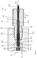
- the capillary connection unit 10 comprises a connection element 11, which has an actuation section 11.1 and a thread 18, wherein the connection element 11 has an axial passage 12 for a capillary 20.
- the connection element 11 is arranged on an end portion 23 of a capillary 20 and guided displaceably on the capillary 20. Furthermore, the connection element 11 is also freely rotatable relative to the capillary 20, wherein the capillary 20 forms the axis of rotation.
- the displaceability of the connection element 11 on the capillary 20 is limited by a stop element 26 which is fixedly connected to the capillary 20.
- thermoplastic material in particular a thermoplastic such as one or more materials of the group comprising fluoroplastics, polyaryletherketones (PAEK), mixtures of Fluoroplastics and polyaryletherketones (PAEK), in particular selected from the group comprising polytetrafluoroethylene (PTFE), polyvinylidene fluoride (PVDF), polyetherketone (PEK), polyetheretherketone (PEEK), polyetherketone ketone (PEKK), polyetheretheretherketone (PEEEK), polyetherketoneetherketone ketone (PEKEKK), and polyetheretherketoneetherketone (PEEKEK), preferably polyether ketone (PEK), polyetheretherketone (PEEK) and polyetherketone ketone (PEKK), and most preferably polyetheretherketone (PEEK), arranged
- the capillary 20 is present in the form of two shells and has an inner capillary or first shell 21 and an outer capillary or second shell 22 which are connected to each other (eg cohesively or non-positively), wherein the inner capillary eg of a thermoplastic, glass or fused silica , Metal, such as stainless steel or titanium, or ceramic is formed.
- the outer capillary or second shell 22 is formed for example as a stainless steel or titanium tube, which is non-positively or materially connected to the inner capillary.
- the second shell 22 could also be formed from a thermoplastic.
- thermoplastics for the capillary shells come, as well as the sealing element 13, one or more materials from the group including fluoroplastics, polyaryletherketones (PAEK), mixtures of fluoroplastics and polyaryletherketones (PAEK), in particular selected from the group comprising polytetrafluoroethylene (PTFE), polyvinylidene fluoride (PVDF ), Polyether ketone (PEK), polyetheretherketone (PEEK), polyetherketone ketone (PEKK), polyetheretheretherketone (PEEEK), polyetherketoneetherketone ketone (PEKEKK), and polyetheretherketoneetherketone (PEEKEK), preferably polyetherketone (PEK), polyetheretherketone (PEEK) and polyetherketone ketone (PEKK) ,
- the ceramic may consist of one or more materials selected from the group consisting of carbides, nitrides and / or oxides (or others) or a ceramic of one or more elements selected from the group consisting of boron, aluminum, silicon, germanium, zirconium, cerium, Rare earths (or others).
- the ceramic material is preferably selected from the group consisting of silicon carbide, silicon nitride, silicon oxide, zirconium oxide, zirconium carbide, titanium oxide, aluminum oxide, titanium carbide and composites and / or mixtures thereof.
- fused silica silica glass (pure silicon dioxide), which is obtained by melting quartz (crystalline silicon dioxide) at temperatures above 1705 degrees Celsius with subsequent cooling.
- the cooled melt is amorphous, ie disordered.
- the high chemical inertness, the high temperature resistance and the transparency as well as the thinnest capillaries made of fused silica can be extremely advantageous.
- the Kapillaran gleichhow 10 projects beyond the inner capillary 21 to the free end 24 of the capillary 20 through the outer capillary 22, for example, by a few tenths of a millimeter to several millimeters.
- the sealing element 13 is in this end region at the free end 24 of the capillary 20 directly bonded to the inner capillary 21 connected. In the rear region, the sealing element 13 is also materially connected to the outer capillary 22, for example glued or welded.
- a securing element 16 in the form of a metallic sleeve which is firmly connected to the outer capillary 22, adjoins the sealing element 13 against the sealing element 13.
- the solid connection between the metallic outer capillary 22 and the securing element 16 made of metal, for example, by welding or soldering or by gluing both parts together.
- On the securing element 16 at least one tooth 17.1 is formed, which forms a toothing 17 together with counter teeth of the sealing element, wherein the teeth 17.1 on the fuse element 16 undercuts 17.2 form, in addition to a good material connection with the sealing element 13 and a positive mechanical connection with the To produce sealing element 13. Via the securing element 16, a rotational securing of the sealing element 13 with respect to the capillary 20 is produced.
- the capillary connection unit 10 also has a metallic sleeve element 14, which surrounds the sealing element 13 at least in regions radially on the outside and which is of circular cylindrical design.
- the metallic sleeve element 14 has a first end 14.1 facing the connection element 11 and a second end 14.2 facing away from the connection element 11. Starting from its second end 14. 2, the sleeve element 14 has a circular-cylindrical receiving region 14. 3 facing away from the connecting element 11 for the sealing element 13 and the securing element 16.
- An inner diameter d iH of the sleeve member 14 in the receiving area 14.3 is at least as large as the outer diameter d aD of the sealing element 13, so that the sealing element 13 and the securing element 16, which has the same outer diameter as the sealing element 13, well in the receiving area 14.3 of Move sleeve element into it.
- the inner diameter d iH of the sleeve element 14 in the receiving region 14.3 but at most 5/100 mm larger than the outer diameter d aD of the sealing element 13, so that the sealing element 13, when it is compressed, can create a sealing against the sleeve member 14.
- the sleeve member 14 is guided both axially relative to the connecting element 11 and with respect to the capillary 20 and thus also with respect to the sealing element 13.
- the connection element 11 is rotatable relative to the sleeve element 14.
- the securing element 16 can be completely inserted into the receiving area 14.3 be like, from the FIGS. 1, 2, 3 . 4 and 6 seen.
- the sealing element 13 can also be inserted substantially completely into the receiving region 14.3, wherein essentially means that possibly a few hundredths of a millimeter of the sealing element 13, the second end 14.2 of the sleeve member 14 may still project beyond.
- the connection element 11 still has a circular cylindrical receptacle in the form of a blind hole 19.
- the sleeve element 14 can be accommodated at least partially in the blind hole 19 or the receptacle in the connection element 11. It then rests with its connecting element 11 facing first end 14.1 on a stop surface 19.1 of the connecting element 11 at.
- the first end 14.1 of the sleeve member 14 in this case has a first thrust surface 15.1, to which a thrust force F can be transmitted from the stop surface 19.1 on the sleeve member 14 when the Kapillaran gleichisme 10, as in Fig. 6 to produce a fluid connection between the counter element 30 and the Kapillaran gleichhow 10.
- the counter-element 30 has a counter-thread 38 which is engageable with the thread 18 of the connecting element 11 in engagement.
- the sleeve member 14 further includes a radially inner second thrust surface 15.2, which is axially spaced from the, the connecting member 11 remote from the second end 14.2.
- the thrust force F which is exerted by the connecting element 11 when screwed into the counter-element 30 on the sleeve member 14, are passed to the sealing element 13. This forwarding takes place in the present embodiment, mediated via the securing element 16, which is toothed with the sealing element 13.
- r i, min is the minimum inner radius of the sleeve member 14
- r S is the outer radius of the second thrust surface 15.2
- r H is the outer radius of the sleeve member 14 (see FIG. Fig. 4 ).
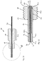
- FIGS. 7 to 10 a further embodiment of a capillary connection unit 10 according to the invention is shown.
- This differs from the previously described Kapillaran gleichiser according to the FIGS. 1 to 6 in that the sealing element 13 is not only toothed with the securing element 16 (see toothing 17 in FIGS FIGS. 8 to 10 ), but also in that the sealing element 13 completely encloses the securing element 16 along its axial length, so that the sealing element 13 with its end located in the receiving space 14.3 of the sleeve element 14 or its end surface located there on the second thrust surface 15.2 of the metallic sleeve element 14th is applied.
- the embodiment shown here corresponds to the capillary connection unit 10 of the above-described Kapillaran gleichiser 10 according to the FIGS. 1 to 6 , so that with respect to not mentioned here reference numerals and features is fully incorporated by reference to the preceding description of the FIGS. 1 to 6 ,
- FIGS. 11 and 12 a further embodiment of a capillary connection unit 10 according to the invention is shown.
- This is different from the one in the FIGS. 1 to 6 illustrated embodiment of a Kapillaran gleichiser 10 characterized in that the inner capillary or first shell 21 of the capillary 20 is formed as a glass capillary, while the outer capillary or second shell 22 of the capillary 20 is formed from a thermoplastic, eg PEEK.
- this embodiment of a capillary connection unit 10 only one sealing element 13 and no additional securing element are arranged in the receiving space 14.3 of the metallic sleeve element 14.
- This sealing element 13 made of a thermoplastic material, for example PEEK is firmly bonded to the outer capillary 22 made of thermoplastic material, such as PEEK, for example, with this entire surface welded.
- the sleeve member 14 is axially displaceable relative to the connection element 11 and the sealing element 13 with the capillary 20 axially displaceable relative to the sleeve member 14.
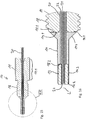
- FIGS. 13 and 14 a further embodiment according to the invention of a capillary connection unit 10 is shown.
- the capillary 20 is not formed Moschalig and consists of only one material.
- the capillary is entirely formed of stainless steel, but it could alternatively be made of a thermoplastic, such as PEEK or glass.
- the sealing element 13 is presently made of a thermoplastic, for example PEEK and is in turn toothed by means of the toothing 17 with the securing element 16, as in the embodiment of the FIGS. 1 to 6 the case is.
- reference numerals and features of this embodiment of the Kapillaran gleichtechnik 10 is fully to the foregoing description of the embodiment according to the FIGS. 1 to 6 directed.
- FIGS. 15 and 16 a further embodiment of a Kapillaran gleichiser 10 according to the invention is reproduced, which thereby differs from the in the FIGS. 11 and 12 illustrated embodiment that the sleeve member 14 is not received in a blind hole of the connection element 11, but that the sleeve member 14 has a connection element 11 facing radially umfteilliche flange-like widening 14.4, whereby a large-scale first thrust surface 15.1 is generated on the sleeve member 14. This can be brought into abutment over a large area on the stop surface 19.1 of the connection element 11, the stop surface 19.1 being formed in this embodiment of the capillary connection unit 10 by an end face of the connection element 11.
- the capillary 20 is double-shelled in this embodiment and in turn has an inner capillary made of glass, a thermoplastic, such as PEEK or metal, such as stainless steel or titanium on.
- the outer capillary 22 is made of a thermoplastic, for example, made of PEEK, wherein the sealing element 13, which also consists of a thermoplastic, such as PEEK, is materially connected to the outer capillary 22, for example welded thereto.
- the capillary 20 with the sealing element 13 arranged thereon is in turn displaceable relative to the sleeve element 14 (limited) and the sleeve element 14 is limited (displaceable) relative to the connecting element 11.
- a single-shell capillary for example of a thermoplastic, such as PEEK, glass, metal, such as stainless steel or titanium, or one of the above-described ceramics can be used.
Priority Applications (4)
| Application Number | Priority Date | Filing Date | Title |
|---|---|---|---|
| EP16001083.1A EP3244205A1 (fr) | 2016-05-12 | 2016-05-12 | Unite de raccordement capillaire pour appareils d'analyse et appareils medicaux |
| PCT/EP2017/000584 WO2017194193A1 (fr) | 2016-05-12 | 2017-05-12 | Unité de connexion capillaire pour des appareils d'analyse et des appareils médicaux |
| EP17722684.2A EP3455620A1 (fr) | 2016-05-12 | 2017-05-12 | Unité de connexion capillaire pour des appareils d'analyse et des appareils médicaux |
| US16/300,369 US11135593B2 (en) | 2016-05-12 | 2017-05-12 | Capillary connection unit for analysis devices and medical devices |
Applications Claiming Priority (1)
| Application Number | Priority Date | Filing Date | Title |
|---|---|---|---|
| EP16001083.1A EP3244205A1 (fr) | 2016-05-12 | 2016-05-12 | Unite de raccordement capillaire pour appareils d'analyse et appareils medicaux |
Publications (1)
| Publication Number | Publication Date |
|---|---|
| EP3244205A1 true EP3244205A1 (fr) | 2017-11-15 |
Family
ID=56068590
Family Applications (2)
| Application Number | Title | Priority Date | Filing Date |
|---|---|---|---|
| EP16001083.1A Withdrawn EP3244205A1 (fr) | 2016-05-12 | 2016-05-12 | Unite de raccordement capillaire pour appareils d'analyse et appareils medicaux |
| EP17722684.2A Pending EP3455620A1 (fr) | 2016-05-12 | 2017-05-12 | Unité de connexion capillaire pour des appareils d'analyse et des appareils médicaux |
Family Applications After (1)
| Application Number | Title | Priority Date | Filing Date |
|---|---|---|---|
| EP17722684.2A Pending EP3455620A1 (fr) | 2016-05-12 | 2017-05-12 | Unité de connexion capillaire pour des appareils d'analyse et des appareils médicaux |
Country Status (3)
| Country | Link |
|---|---|
| US (1) | US11135593B2 (fr) |
| EP (2) | EP3244205A1 (fr) |
| WO (1) | WO2017194193A1 (fr) |
Cited By (1)
| Publication number | Priority date | Publication date | Assignee | Title |
|---|---|---|---|---|
| US20190176054A1 (en) * | 2017-12-12 | 2019-06-13 | Dionex Softron Gmbh | Plug units, particularly for HPLC, connection system and corresponding use |
Families Citing this family (2)
| Publication number | Priority date | Publication date | Assignee | Title |
|---|---|---|---|---|
| DE102019002641A1 (de) * | 2019-04-10 | 2020-10-15 | Möller Medical Gmbh & Co Kg | Vorrichtung zum Anschließen eines Rohres oder Schlauches, bevorzugt einer Kapillare |
| US11782032B2 (en) | 2019-08-14 | 2023-10-10 | Waters Technologies Corporation | Fitting for fluidic coupling in a chromatography system |
Citations (5)
| Publication number | Priority date | Publication date | Assignee | Title |
|---|---|---|---|---|
| US5669637A (en) * | 1996-05-29 | 1997-09-23 | Optimize Technologies, Inc. | Miniature fitting assembly for micro-tubing |
| DE102009022368B3 (de) | 2009-05-22 | 2010-11-18 | Dionex Softron Gmbh | Steckereinheit und Verbindungssystem für das Verbinden von Kapillaren, insbesondere für die Hochleistungsflüssigkeitschromatographie |
| GB2482175A (en) * | 2010-07-23 | 2012-01-25 | Agilent Technologies Inc | Fitting element with bio-compatible sealing |
| DE102011050037B3 (de) * | 2011-05-02 | 2012-06-14 | Dionex Softron Gmbh | Steckereinheit und Verbindungssystem zum Verbinden von Kapillaren, insbesondere für die Hochleistungsflüssigkeitschromatographie |
| WO2013024345A1 (fr) * | 2011-08-15 | 2013-02-21 | Möller Medical Gmbh | Tube comprenant une gaine métallique munie d'une chemise en matière plastique, destiné à être utilisé dans des applications à basse pression et à haute pression, en particulier en qualité de colonne hplc |
Family Cites Families (3)
| Publication number | Priority date | Publication date | Assignee | Title |
|---|---|---|---|---|
| DE102011082470A1 (de) * | 2011-09-09 | 2013-03-14 | Agilent Technologies Inc. | Fitting mit lokaler Kapillarweitenanpassung |
| US9347056B2 (en) * | 2012-10-26 | 2016-05-24 | Seiko Epson Corporation | Nucleic acid extraction device, and nucleic acid extraction method, nucleic acid extraction kit, and nucleic acid extraction apparatus, each using the same |
| JP6767973B2 (ja) * | 2014-10-23 | 2020-10-14 | アイデックス ヘルス アンド サイエンス エルエルシー | 面シール流体接続システム |
-
2016
- 2016-05-12 EP EP16001083.1A patent/EP3244205A1/fr not_active Withdrawn
-
2017
- 2017-05-12 WO PCT/EP2017/000584 patent/WO2017194193A1/fr unknown
- 2017-05-12 US US16/300,369 patent/US11135593B2/en active Active
- 2017-05-12 EP EP17722684.2A patent/EP3455620A1/fr active Pending
Patent Citations (5)
| Publication number | Priority date | Publication date | Assignee | Title |
|---|---|---|---|---|
| US5669637A (en) * | 1996-05-29 | 1997-09-23 | Optimize Technologies, Inc. | Miniature fitting assembly for micro-tubing |
| DE102009022368B3 (de) | 2009-05-22 | 2010-11-18 | Dionex Softron Gmbh | Steckereinheit und Verbindungssystem für das Verbinden von Kapillaren, insbesondere für die Hochleistungsflüssigkeitschromatographie |
| GB2482175A (en) * | 2010-07-23 | 2012-01-25 | Agilent Technologies Inc | Fitting element with bio-compatible sealing |
| DE102011050037B3 (de) * | 2011-05-02 | 2012-06-14 | Dionex Softron Gmbh | Steckereinheit und Verbindungssystem zum Verbinden von Kapillaren, insbesondere für die Hochleistungsflüssigkeitschromatographie |
| WO2013024345A1 (fr) * | 2011-08-15 | 2013-02-21 | Möller Medical Gmbh | Tube comprenant une gaine métallique munie d'une chemise en matière plastique, destiné à être utilisé dans des applications à basse pression et à haute pression, en particulier en qualité de colonne hplc |
Cited By (2)
| Publication number | Priority date | Publication date | Assignee | Title |
|---|---|---|---|---|
| US20190176054A1 (en) * | 2017-12-12 | 2019-06-13 | Dionex Softron Gmbh | Plug units, particularly for HPLC, connection system and corresponding use |
| US11554330B2 (en) * | 2017-12-12 | 2023-01-17 | Dionex Softron Gmbh | Plug units, particularly for HPLC, connection system and corresponding use |
Also Published As
| Publication number | Publication date |
|---|---|
| US20190091693A1 (en) | 2019-03-28 |
| EP3455620A1 (fr) | 2019-03-20 |
| US11135593B2 (en) | 2021-10-05 |
| WO2017194193A1 (fr) | 2017-11-16 |
Similar Documents
| Publication | Publication Date | Title |
|---|---|---|
| DE102012110991B4 (de) | Steckereinheit und Verbindungssystem zum Verbinden von Kapillaren, insbesondere für die Hochleistungsflüssigkeitschromatographie | |
| DE102009022368B3 (de) | Steckereinheit und Verbindungssystem für das Verbinden von Kapillaren, insbesondere für die Hochleistungsflüssigkeitschromatographie | |
| DE102008059897B4 (de) | Steckereinheit und Verbindungssystem für das Verbinden von Kapillaren, insbesondere für die Hochleistungsflüssigkeitschromatographie | |
| EP1701082B1 (fr) | Portion d'extrémité de conduite à élément d'enfichage surmoulé | |
| EP1355100B1 (fr) | Raccord enfichable pour système fluidique | |
| EP2205299B1 (fr) | Seringue à aiguille interchangeable | |
| DE102008010084B4 (de) | Übertragungselement für axial zu verpressende Werkstückverbindungen sowie Anordnung zur Herstellung einer unlösbaren Verbindung | |
| WO2012149930A1 (fr) | Unité de connecteur et système de liaison destiné à relier des capillaires, en particulier pour la chromatographie liquide haute performance | |
| EP1448927A1 (fr) | Raccord enfichable | |
| EP2192338B1 (fr) | Pièce de raccordement | |
| EP3244205A1 (fr) | Unite de raccordement capillaire pour appareils d'analyse et appareils medicaux | |
| DE112015001853T5 (de) | Hochdruck-Fluid-Verbindungsanordnungen | |
| DE102017102396A1 (de) | Verbindungsstück für die Fluidchromatographie | |
| EP3516284B1 (fr) | Ensemble connecteur enfichable pour conduites de fluide ainsi que procédé permettant de relier des conduites de fluide | |
| DE102017122394A1 (de) | Verbindungsstück mit kleinem Totvolumen für die Fluidchromatographie | |
| DE10207201A1 (de) | Pressfitting | |
| DE10104508A1 (de) | Schlauch-Verbindung | |
| DE112004001426T5 (de) | Fluidendstück | |
| EP2228581B1 (fr) | Raccord de tuyauterie doté d'une pièce de serrage | |
| WO2014180909A2 (fr) | Système de liaison et procédé de liaison d'éléments de guidage de fluides | |
| EP0461308B1 (fr) | Pièce intermédiaire pour la liaison de tuyaux en matière plastique avec armature métallique, en particulier dans les domaines sanitaires et de chauffage | |
| WO2010028872A1 (fr) | Assemblage de canalisation non détachable | |
| WO2015086799A1 (fr) | Élément filtrant en céramique pour applications de chromatographie, en particulier de chromatographie liquide à haute performance (hpcl), et système de chromatographie, en particulier système hpcl, comprenant un élément filtrant en céramique | |
| EP2369212B1 (fr) | Dispositif de raccordement | |
| EP1978290A1 (fr) | Dispositif destiné au raccordement d'une conduite tubulaire, en particulier d'un tuyau flexible, sur un élément de raccordement |
Legal Events
| Date | Code | Title | Description |
|---|---|---|---|
| PUAI | Public reference made under article 153(3) epc to a published international application that has entered the european phase |
Free format text: ORIGINAL CODE: 0009012 |
|
| AK | Designated contracting states |
Kind code of ref document: A1 Designated state(s): AL AT BE BG CH CY CZ DE DK EE ES FI FR GB GR HR HU IE IS IT LI LT LU LV MC MK MT NL NO PL PT RO RS SE SI SK SM TR |
|
| AX | Request for extension of the european patent |
Extension state: BA ME |
|
| STAA | Information on the status of an ep patent application or granted ep patent |
Free format text: STATUS: THE APPLICATION IS DEEMED TO BE WITHDRAWN |
|
| 18D | Application deemed to be withdrawn |
Effective date: 20180516 |