EP1355100B1 - Raccord enfichable pour système fluidique - Google Patents
Raccord enfichable pour système fluidique Download PDFInfo
- Publication number
- EP1355100B1 EP1355100B1 EP03008547A EP03008547A EP1355100B1 EP 1355100 B1 EP1355100 B1 EP 1355100B1 EP 03008547 A EP03008547 A EP 03008547A EP 03008547 A EP03008547 A EP 03008547A EP 1355100 B1 EP1355100 B1 EP 1355100B1
- Authority
- EP
- European Patent Office
- Prior art keywords
- plug
- housing part
- coupling according
- outer housing
- detent
- Prior art date
- Legal status (The legal status is an assumption and is not a legal conclusion. Google has not performed a legal analysis and makes no representation as to the accuracy of the status listed.)
- Expired - Lifetime
Links
Images


Classifications
-
- F—MECHANICAL ENGINEERING; LIGHTING; HEATING; WEAPONS; BLASTING
- F16—ENGINEERING ELEMENTS AND UNITS; GENERAL MEASURES FOR PRODUCING AND MAINTAINING EFFECTIVE FUNCTIONING OF MACHINES OR INSTALLATIONS; THERMAL INSULATION IN GENERAL
- F16L—PIPES; JOINTS OR FITTINGS FOR PIPES; SUPPORTS FOR PIPES, CABLES OR PROTECTIVE TUBING; MEANS FOR THERMAL INSULATION IN GENERAL
- F16L37/00—Couplings of the quick-acting type
- F16L37/08—Couplings of the quick-acting type in which the connection between abutting or axially overlapping ends is maintained by locking members
- F16L37/084—Couplings of the quick-acting type in which the connection between abutting or axially overlapping ends is maintained by locking members combined with automatic locking
- F16L37/088—Couplings of the quick-acting type in which the connection between abutting or axially overlapping ends is maintained by locking members combined with automatic locking by means of a split elastic ring
-
- F—MECHANICAL ENGINEERING; LIGHTING; HEATING; WEAPONS; BLASTING
- F16—ENGINEERING ELEMENTS AND UNITS; GENERAL MEASURES FOR PRODUCING AND MAINTAINING EFFECTIVE FUNCTIONING OF MACHINES OR INSTALLATIONS; THERMAL INSULATION IN GENERAL
- F16L—PIPES; JOINTS OR FITTINGS FOR PIPES; SUPPORTS FOR PIPES, CABLES OR PROTECTIVE TUBING; MEANS FOR THERMAL INSULATION IN GENERAL
- F16L2201/00—Special arrangements for pipe couplings
- F16L2201/10—Indicators for correct coupling
-
- F—MECHANICAL ENGINEERING; LIGHTING; HEATING; WEAPONS; BLASTING
- F16—ENGINEERING ELEMENTS AND UNITS; GENERAL MEASURES FOR PRODUCING AND MAINTAINING EFFECTIVE FUNCTIONING OF MACHINES OR INSTALLATIONS; THERMAL INSULATION IN GENERAL
- F16L—PIPES; JOINTS OR FITTINGS FOR PIPES; SUPPORTS FOR PIPES, CABLES OR PROTECTIVE TUBING; MEANS FOR THERMAL INSULATION IN GENERAL
- F16L2201/00—Special arrangements for pipe couplings
- F16L2201/20—Safety or protective couplings
Definitions
- the present invention relates to a plug-in coupling for fluidic systems, in particular for CO 2 - and fuel-carrying systems, consisting of a housing and a plug in the housing plug, wherein the plug with a plug shank into a receiving opening of the housing sealed by at least one seal plugged and therein by means of a locking device consisting of at least one latching element arranged on the plug and a locking shoulder cooperating with the locking element, in the inserted state against loosening can be locked, and wherein the housing is made in two parts, by an inner housing part and one with the inner Housing releasably connectable and the inner housing part substantially comprehensive - outer housing part.
- Such a plug-in coupling is known from EP 0 766 033 B1.
- a plug-in coupling for in particular pneumatic pressure fluid systems described which consists of two coupling parts, of a housing part and a plug part, wherein the plug part with a plug shank over at least one sitting in an annular groove of a coupling part and with a circumferential Sealed sealing surface of the other coupling part cooperating circumferential seal in a receiving opening of the housing part can be inserted and by means of a Locking device can be locked against loosening.
- the locking device is It is designed such that a partially inserted pre-locking position and a completely inserted Full rest position are ensured, in the Vorrast ein such a incomplete sealing is present, that in the case of pressurization with a Pressure medium, in particular compressed air, a defined limited, be perceived Leakage, in particular in the form of an acoustically perceptible leak sound, occurs, and wherein in the Vollrast ein on the voltage applied to the sealing surface Circumferential seal a complete, pressure-tight seal is present.
- the locking device consists of two axially arranged one behind the other on the plug Locking elements and a cooperating with the locking element latching shoulder, in the coupling housing part inside the receiving opening for the Plug part is located.
- a disadvantage of such a known plug-in coupling is in one-piece design of the Housing first, that the plug part after it in the coupling housing part introduced and locked in it by the latching, only with destruction of the Plug-in coupling can be separated again from the coupling part. Therefore, according to EP 0 766 033 B1 also provides a design in which the housing part such from two detachably connected parts, a base part and a preferred as Cap screw trained insert, is that after loosening the insert from the base part of the plug part together with a part of the locking device and the insert can be removed.
- This technical Solution is particularly suitable for devices in which the base part part a larger machine part, such as a hydraulic or pneumatic connection block, is.
- plug-in coupling A similar as the above-described embodiment of a plug-in coupling describes also the US 4 105 226 A.
- this known plug-in coupling is additional provided that the locking shoulder unilaterally in the entrance area of the receiving opening is formed on the outer housing part.
- This will be a nondestructive Disassembly allows.
- the plug-in coupling After plugging in the plug and a complete Locking with the housing, the plug-in coupling by releasing the connection between the outer and the inner housing part, in particular by a Unscrew the designed as a union nut outer housing part, solved become.
- the inner housing part and the plug can remain rotation-free, so that the plug is required, e.g. Fixed as screwed executed and the Housing with a relatively rigid pipe, which allows only small axial movements, can be connected.
- the present invention is based on the object, an altemative, in particular suitable for continuous, interconnecting hose or piping, generic plug-in coupling to create an increased connection security guaranteed.
- this is due to the presence of an annular, in the Basic shape essentially hollow cylindrical, on the housing, in particular on reaches the outer housing part of the housing, retractable security part, the in a locked state, a rotation of the insertable into the housing Stekkers prevented from the housing.
- connection assurance can advantageously thereby in particular take place that in the locked state a positive connection between the Secured part and the housing and / or the plug part is made.
- plug-in coupling according to the invention can further advantageously also a separation of the known embodiment of the inner housing part at the same time inherited functions "holding the plug” and “sealing” done by the function "holding the plug” to be transferred to the outer housing part can and only the function "sealing" is met by the inner housing part.
- a high-precision design of contact surfaces of the inner housing part for the peripheral seal at the same time very slender Execution of the entire plug-in coupling according to the invention. So is the invention Plug-in coupling suitable, if a suitable seal is selected Pressures of 200 bar and higher at temperatures of about 250 ° C to withstand.
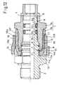
- FIGS. 1 and 2 there is a plug-in coupling for fluidic systems, in particular for CO 2 and fuel-carrying systems, of a housing 1 and of a plug-in housing 1 plug 2, wherein the plug 2 with a plug shank. 3 in a receiving opening 4 of the housing 1 by at least one peripheral seal 5 can be inserted sealed.
- the plug 2 can be locked in the receiving opening 4 by means of a (unspecified as a whole) locking device in the inserted state against loosening.
- the locking device consists of at least one locking element - in the illustrated embodiment of two axially arranged one behind the other on the plug 2 Locking elements 6, 7 - and from one each with a locking element 6, 7th cooperating locking shoulder 8.
- the locking elements 6, 7 are each by a in each one (unspecified) annular groove of the plug 2 held snap ring educated.
- the housing 1 is designed in two parts, by being made of an inner housing part 1a, which forms the main part of the receiving opening 4, and one with the inner Housing part 1a releasably connectable and the inner housing part 1a substantially comprehensive outer housing part 1b consists.
- the locking shoulder 8 is single-ended in the entrance area 4a of the receiving opening 4 formed on the outer housing part 1b.
- the outer housing part 1 b may be preferable to the inner one Housing part 1a screwed union nut may be formed. (The corresponding Internal and external threads are shown in the enlarged view of FIG. 4 and summarily denoted by reference G.)
- the plug 2 For better centering - and introduction of the fluid seal 5, the plug 2 one end opposite the other body of the plug 2 in diameter reduced insertion pin 9 with a tapered tip on.
- the Circumferential seal 5 surrounds the insertion pin 9 and is at the first Embodiment of the invention at the foot of the insertion pin 9 in transition to the shaft 3 arranged.
- the peripheral seal can in the simplest case with lower requirements, as in Fig. 4, be formed of an O-ring or, as in the other figures represented, consist of a seal set, consisting of a two-lip ring and a spring element embedded therein is formed. It can at least partially, in particular the double-lip ring, made of a polymeric fluorine-carbon compound, like PTFE, exist (fluorine compound seal).
- the plug 2 may preferably, as shown, one with respect to the rest of the body of the plug 1 in diameter enlarged collar 10 as a stop for the housing 1, in particular for the outer housing part 1 b, wherein on the plug 2 - axially adjacent to the collar 10 lying - one in particular from an O-ring formed dirt seal 11 a can be arranged.
- the plug 2 and both the inner housing part 1a, and the outer Housing part 1b may preferably made of metallic materials, in particular Aluminum or high alloy stainless steel alloys. Such a Material is for example AlMgSi 1.
- FIG. 3 shows, as already mentioned, a first assembly step of the invention Plug-in coupling. This is that the outer housing part 1b and the inner Housing part 1 a screwed together. Like the graphic representation can be seen, engages over the outer housing part 1b, the inner housing part 1 a end in the entrance area 4 a of the receiving opening. 4
- the outer housing part 1 b in the entrance area 4 a of the receiving opening. 4 starting from an inner diameter which is larger than the outer diameter the snap rings (locking elements 6, 7) in the expanded state, conically on a Inner diameter tapers, which is about the outer diameter of the snap rings in the compressed state, the circlips are in the entrance area 4a of the receiving opening 4 compressed and then spring after they Entrance area 4a have happened, each time again and lie down behind the Locking shoulder, so that the plug is no longer pulled out of the housing 1 can be.
- a disassembly sleeve 12 is screwed into the outer housing part 1b ( Figures 6 and 7).
- a tubular disassembly sleeve 12th usable which in the input region 13a of an axial opening 13, starting from an inner diameter that is larger than the outer diameter of the snap rings (Locking elements 6, 7) in the expanded state, conically to an inner diameter tapered, which is about the outside diameter of the snap rings in the compressed State corresponds.
- the outer diameter of the disassembly sleeve 12 is smaller than that Inner diameter of the outer housing part 1b.
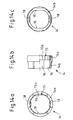
- FIGS. 9 to 13 and 14 a to 14 c show an embodiment the invention.
- a housing 1 As in particular the exploded view in Fig. 9 and the illustrations in In the assembled state in Figs. 12 and 13, the second embodiment is included the invention, a housing 1, an inner housing part 1a and an outer Housing part 1b has, as is the case in the embodiment of FIG. 1 to 8.
- the basic structure is also the same as in this embodiment.
- the Embodiment of the plug-in coupling according to the invention an annular, in the Basic shape substantially hollow cylindrical, on the outer housing part 1b slidable, preferably made of plastic securing part 14, the in a locking state (Fig. 13) a rotation of the plug 2 relative to the Housing 1 prevented.
- the securing part 14, shown in Fig. 9 and Fig. 14a to 14c as a single part has a first annular region 14a and a second annular region 14b, wherein the first ring portion 14a in the locked state on the plug 2, in particular to whose collar 10, rotationally fixed.
- the second ring portion 14b is at the outer housing part 1 b, in particular on its outer surface AF, rotationally fixed and also fixable without displacement in the axial direction.
- the securing part 14 in the first ring portion 14a to Fixing on the plug 2 an internal toothing 15 and the collar 10 of the Plug 2 is designed as a polygon. In this way comes in the locked state a positive connection between the two parts. This has it proved to be favorable if the internal toothing 15 12 to 36 teeth 15 a, in particular 24 teeth 15a.
- the drawing illustrates that the securing part 14 in the second ring portion 14b for rotationally fixed to the outer housing part 1b has at least one key surface 16, preferably two key surfaces 16, which are flattened relative to the circular outer periphery of the part and in Locking state (Fig. 13) of the securing part 14 for positive engagement with each a corresponding key surface 17 on the outer surface AF of the outer Housing part 1b is determined.
- Fig. 13 Locking state
- the securing part 14 also has in the second ring portion 14b in axial Direction shift-free fixing to the outer housing part 1b at least a particularly resilient locking lug 18, preferably two locking lugs 18, on, each of which - as Fig. 9 illustrates - by a longitudinal slots of the security part 14 may be made in its lateral surface.
- these locking lugs 18 are each for positive and non-positive Connection formation, each with a corresponding groove 19a in the outer surface AF of the outer housing part 1b determined.
- the locking lugs 18 are - as well as the key surfaces 16 - the security part 14 each diametrically opposite, while the locking lugs 19 with respect to the plane the key surfaces 17 are offset by about 90 °.
- the locking lugs 18 which on the securing part 14 in the second ring portion 14b for fixing in the axial direction without displacement on the outer housing part 1b are provided, the securing part 14 not only in its active locking state, but also in an inactive, non-locking state of the security part 14 each form-fitting and non-positive on the outer housing part 1b set. It comes it to cooperate with a respective corresponding groove 19b in the Outside surface AF of the outer housing part 1b. This groove 19b extends in each case circumferentially parallel to the groove 19a, which is fixed in the locked state is determined.
- the assembly and disassembly operations of the embodiment according to the invention are - as the constructive Basic construction - the same as in the first execution of Plug-in coupling, which is illustrated in Fig. 10 thereby, that in turn shows a disassembly sleeve 12 for the outer threaded portion 1b, which next to her External thread (denoted by the reference numeral 12a) and a collar 12b which can serve as a force attack for a key.
- the assembly of the Secured securing part 14 this can be with the assembly of the housing 1 with the plug 2 from a position, as shown in Fig. 9, on the outer Housing part 1 b pushed and initially in the manner, as shown in FIG.
- FIG. 12 the plug-in coupling is in the assembly or operating state (FIG. 12) can then the secured state, the locking state of the securing part 14 according to FIG. 13, be prepared by the locking connections of the locking lugs 18 with the grooves 19b be lifted and the securing member 14 is axially displaced until his teeth 15a engage around the collar 10 of the plug 2 in a form-fitting manner in the first annular region 14a and until the locking lugs 18 engage in the grooves 19 a provided for this purpose.
- the plug-in coupling according to the invention differs also the type of sealing of the plug 2 of the first, not inventive design. So are in the Contrary to the first embodiment on the plug 2 two circumferential seals 5a, 5b intended. These circumferential seals 5a, 5b surround the insertion pin. 9 and are each in a groove 9a located in the shell M of the insertion pin 9, 9b arranged. The grooves 9a, 9b extend circumferentially and parallel to each other.
- the circumferential seals 5a, 5b located therein can be optimized the sealing effect of the same material or from different Be made of materials.
- the securing part 14 even without the localization of the locking shoulder 8 am outer housing part 1b is effective and of technical importance.
- the grooves 19b in the outer surface AF of the outer housing part 1 b, for cooperation with the Locking lugs 18 in the second ring portion 14b of the securing part 14 in the inactive, not securing state of the securing part 14 are determined, primarily have a holding function for the securing part 14. In addition, they can be advantageous, however in addition to performing a signal function by, if they are visible on it indicate that the locking state is present.
- the grooves 19b may have a mark such as a color mark.
- a release torque of the screwed to the inner housing part 1a outer housing part 1b is greater than a torque, which in its action on the securing part 14 brings about a breakage of the securing part 14.
- These Voting can be done by an appropriate choice of the material of the security part 14 can be achieved.
Landscapes
- Engineering & Computer Science (AREA)
- General Engineering & Computer Science (AREA)
- Mechanical Engineering (AREA)
- Quick-Acting Or Multi-Walled Pipe Joints (AREA)
Claims (30)
- Raccord enfichable pour des systèmes fluidiques, en particulier pour des systèmes véhiculant du CO2 et du carburant, se composant d'un boítier (1) et d'un connecteur (2) pouvant être enfiché dans le boítier (1), dans lequel le connecteur (2) peut être enfiché avec un fût de connecteur (3) dans une ouverture de réception (4) du boítier (1) en étant rendu étanche par au moins un joint circulaire (5, 5a, 5b) et peut y être verrouillé dans l'état enfiché contre une désolidarisation à l'aide d'un dispositif de verrouillage se composant d'au moins un élément d'arrêt cranté (7) disposé sur le connecteur (2) et d'un épaulement d'arrêt cranté (8) agissant de concert avec l'élément d'arrêt cranté (7) et dans lequel le boítier (1) est réalisé en deux parties par le fait qu'il se compose d'une partie de boítier intérieure (1a) et d'une partie de boítier extérieure (1b) pouvant être reliée de manière amovible avec la partie de boítier intérieure (1a) et entourant sensiblement la partie de boítier intérieure (1a), caractérisé par un élément de sécurité (14) de forme annulaire avec un profil de base qui est sensiblement celui d'un cylindre creux, lequel peut être enfilé sur le boítier (1), en particulier sur la partie de boítier extérieure (1b) du boítier (1), et lequel évite dans un état de verrouillage une rotation par rapport au boítier (1) du connecteur (2) pouvant être enfilé dans le boítier (1).
- Raccord enfichable selon la revendication 1, caractérisé en ce que la partie de boítier extérieure (1b) est configurée comme écrou d'accouplement pouvant faire l'objet d'une liaison vissée avec la partie de boítier intérieure (1a).
- Raccord enfichable selon la revendication 1 ou 2, caractérisé en ce que la partie de boítier extérieure (1b) recouvre dans la zone d'entrée (4a) de l'ouverture de réception (4) l'extrémité de la partie de boítier intérieure (1a).
- Raccord enfichable selon l'une quelconque des revendications 1 à 3, caractérisé par au moins deux joints circulaires (5a, 5b).
- Raccord enfichable selon l'une quelconque des revendications 1 à 4, caractérisé en ce que le connecteur (2) comprend du côté frontal un ergot d'introduction (9) dont le diamètre est réduit, en particulier par rapport au reste du corps du connecteur (2).
- Raccord enfichable selon la revendication 5, caractérisé en ce qu'au moins un joint circulaire (5) entoure l'ergot d'introduction (9) et est disposé au pied de l'ergot d'introduction (9).
- Raccord enfichable selon la revendication 5, caractérisé en ce qu'au moins un joint circulaire (5a, 5b), de préférence deux joints circulaires (5a, 5b), entoure(nt) l'ergot d'introduction (9) et est(sont) respectivement disposé(s) dans une rainure (9a, 9b) se trouvant dans l'enveloppe (M) de l'ergot d'introduction (9).
- Raccord enfichable selon l'une quelconque des revendications 1 à 7, caractérisé en ce que, respectivement dans l'état d'enfichage du connecteur (2), le joint circulaire (5, 5a, 5b) repose avec son bord extérieur sur le côté intérieur de la partie de boítier intérieure (1a).
- Raccord enfichable selon l'une quelconque des revendications 1 à 8, caractérisé en ce que le joint circulaire (5, 5a, 5b) est respectivement formé par un joint torique.
- Raccord enfichable selon l'une quelconque des revendications 1 à 6, caractérisé en ce que le joint circulaire (5) se compose d'une garniture d'étanchéité qui est formée d'une bague à deux lèvres et d'un élément de ressort qui y est enrobé.
- Raccord enfichable selon l'une quelconque des revendications 1 à 10, caractérisé en ce que le joint circulaire (5, 5a, 5b) est constitué au moins partiellement, et en particulier la bague à deux lèvres, d'un composé de fluor et de carbone polymère, tel que le PTFE.
- Raccord enfichable selon l'une quelconque des revendications 1 à 11, caractérisé en ce que le connecteur (2) comprend, en tant que butée pour le boítier (1), en particulier pour sa partie de boítier extérieure (1b), une collerette (10) dont le diamètre est agrandi par rapport à celui du reste du corps du connecteur (2).
- Raccord enfichable selon la revendication 12, caractérisé en ce que sur le connecteur (2) est disposé - dans une position axiale voisine de la collerette (10) - un joint de protection contre les impuretés (11a) formé en particulier d'un joint torique.
- Raccord enfichable selon la revendication 13, caractérisé en ce que, dans l'état d'enfichage du connecteur (2), le joint de protection contre les impuretés (11a) repose, dans la zone d'entrée (4a) de l'ouverture de réception (4), avec son bord extérieur sur le côté intérieur de la partie de boítier extérieure (1b).
- Raccord enfichable selon l'une quelconque des revendications 1 à 14, caractérisé en ce qu'entre la partie de boítier intérieure (1a) et la partie de boítier extérieure (1b) est disposé un joint de protection contre les impuretés (11b).
- Raccord enfichable selon l'une quelconque des revendications 1 à 15, caractérisé en ce que le connecteur (2) ainsi que la partie de boítier intérieure (1a) et la partie de boítier extérieure (1b) se composent de matériaux métalliques, en particulier d'alliages d'aluminium ou d'alliages d'aciers spéciaux fortement alliés.
- Raccord enfichable selon l'une quelconque des revendications 1 à 15, caractérisé en ce que sur le connecteur (2) est disposé un autre élément d'arrêt cranté (6).
- Raccord enfichable selon l'une quelconque des revendications 1 à 16, caractérisé en ce que sur le connecteur (2) est disposé un élément d'arrêt cranté supplémentaire (6), et ceci de telle façon que, par cet élément d'arrêt cranté supplémentaire (6), est définie en interaction avec l'épaulement d'arrêt cranté (8) une position d'arrêt cranté préliminaire partiellement enfichée et que, par l'autre élément d'arrêt cranté (7), est définie en interaction avec l'épaulement d'arrêt cranté (8) et lors de la poursuite de l'enfichage du connecteur (2) une position d'arrêt cranté complet totalement enfichée, alors que dans la position d'arrêt cranté préliminaire il existe une étanchéité incomplète telle que, dans le cas d'une mise sous pression du fluide, en particulier d'un gaz, il se produit une fuite définie, limitée et perceptible, en particulier sous la forme d'un bruit de fuite acoustiquement perceptible, et alors que dans la position d'arrêt cranté complet il existe une étanchéité complète par rapport à la pression, laquelle est assurée par le joint circulaire (5) s'appuyant sur la surface d'étanchéité.
- Raccord enfichable selon l'une quelconque des revendications 1 à 18, caractérisé en ce que l'élément d'arrêt cranté (7) ou les éléments d'arrêt crantés (6, 7) est(sont) formé(s) respectivement par une bague fendue maintenue dans respectivement une rainure circulaire du connecteur (2).
- Raccord enfichable selon la revendication 19, caractérisé en ce que, dans la zone d'entrée (4a) de l'ouverture de réception (4), la partie de boítier extérieure (1b) - en partant d'un diamètre intérieur qui est plus grand que le diamètre extérieur de la bague fendue lorsqu'elle se trouve dans l'état d'extension - se réduit en forme de cône jusqu'à un diamètre intérieur qui correspond approximativement au diamètre extérieur de la bague fendue lorsqu'elle se trouve dans l'état de compression.
- Raccord enfichable selon la revendication 19 ou 20, caractérisé par un manchon de démontage (12) pouvant être vissé dans la partie de boítier extérieure (1b) à la place de la partie de boítier intérieure (1a) et lequel - en partant d'un diamètre intérieur qui est plus grand que le diamètre extérieur de la bague fendue lorsqu'elle se trouve dans l'état d'extension - se réduit, en particulier dans la zone d'entrée (13a) d'une ouverture axiale (13), en forme de cône jusqu'à un diamètre intérieur qui correspond approximativement au diamètre extérieur de la bague fendue lorsqu'elle se trouve dans l'état de compression.
- Raccord enfichable selon l'une quelconque des revendications 1 à 21, caractérisé en ce que l'épaulement d'arrêt cranté (8) est formé à une extrémité sur la partie de boítier extérieure (1b) dans une zone d'entrée (4a) de l'ouverture de réception (4).
- Raccord enfichable selon l'une quelconque des revendications 1 à 22, caractérisé en ce que l'élément de sécurité (14) comprend une première zone annulaire (14a) et une deuxième zone annulaire (14b), la première zone annulaire (14a) pouvant être immobilisée de manière résistante à la torsion sur le connecteur (2), en particulier sur sa collerette (10), et la deuxième zone annulaire (14b) pouvant être immobilisée de manière résistante à la torsion et sans possibilité de glissement dans le sens axial sur la partie de boítier extérieure (1b), en particulier sur sa surface extérieure (AF).
- Raccord enfichable selon l'une quelconque des revendications 1 à 23, caractérisé en ce que, pour sa fixation sur le connecteur (2), l'élément de sécurité (14) comprend dans la première zone annulaire (14a) une denture intérieure (15), la collerette (10) du connecteur (2) étant configurée comme polygone.
- Raccord enfichable selon la revendication 24, caractérisé en ce que la denture intérieure (15) comprend 12 à 36 dents (15a), en particulier 24 dents (15a).
- Raccord enfichable selon les revendications 23 à 25, caractérisé en ce que, dans la deuxième zone annulaire (14b), l'élément de sécurité (14) comprend pour la fixation de manière résistante à la torsion sur la partie de boítier extérieure (1b) au moins une surface de renforcement (16), de préférence deux surfaces de renforcement (16), qui, dans l'état de blocage de l'élément de sécurité (14), est(sont) destinée(s) à assurer un appui en complémentarité de forme sur respectivement une surface de renforcement correspondante (17) se trouvant sur la surface extérieure (AF) de la partie de boítier extérieure (1b).
- Raccord enfichable selon l'une quelconque des revendications 23 à 26, caractérisé en ce que, dans la deuxième zone annulaire (14b), l'élément de sécurité (14) comprend pour la fixation sans possibilité de glissement dans le sens axial sur la partie de boítier extérieure (1b) au moins un taquet d'arrêt (18) configuré en particulier de manière souple, de préférence deux taquets d'arrêt (18), qui, dans l'état de blocage de l'élément de sécurité (14), est(sont) destiné(s) respectivement à assurer une interaction en complémentarité de forme et en complémentarité de forces avec respectivement une rainure correspondante (19a) se trouvant dans la surface extérieure (AF) de la partie de boítier extérieure (1b).
- Raccord enfichable selon l'une quelconque des revendications 23 à 27, caractérisé en ce que, dans la deuxième zone annulaire (14b), l'élément de sécurité (14) comprend pour la fixation sans possibilité de glissement dans le sens axial sur la partie de boítier extérieure (1b) au moins un taquet d'arrêt (18), de préférence deux taquets d'arrêt (18), qui, dans un état inactif et n'assurant pas de sécurité de l'élément de sécurité (14), est(sont) destiné(s) respectivement à assurer une interaction en complémentarité de forme et en complémentarité de forces avec respectivement une rainure correspondante (19b) se trouvant dans la surface extérieure (AF) de la partie de boítier extérieure (1b).
- Raccord enfichable selon la revendication 28, caractérisé en ce que la rainure (19b) se trouvant dans la surface extérieure (AF) de la partie de boítier extérieure (1b), laquelle est destinée à assurer dans l'état inactif et n'assurant pas de sécurité de l'élément de sécurité (14) une interaction avec le taquet d'arrêt (18) ou avec les taquets d'arrêt (18) se trouvant dans la deuxième zone annulaire (14b) de l'élément de sécurité (14), comprend un marquage, tel qu'un marquage à la peinture.
- Raccord enfichable selon l'une quelconque des revendications 1 à 29, caractérisé en ce qu'un couple de desserrage de la partie de boítier extérieure (1b) vissée sur la partie de boítier intérieure (1a) est plus important qu'un couple de torsion qui conduit à une rupture de l'élément de sécurité (14) lorsqu'il est appliqué à l'élément de sécurité (14).
Priority Applications (5)
| Application Number | Priority Date | Filing Date | Title |
|---|---|---|---|
| DE20314133U DE20314133U1 (de) | 2003-04-14 | 2003-09-10 | Verbindungssystem |
| AT04008398T ATE331176T1 (de) | 2003-04-14 | 2004-04-07 | Verbindungssystem für leitungsorgane |
| DE502004000793T DE502004000793D1 (de) | 2003-04-14 | 2004-04-07 | Verbindungssystem für Leitungsorgane |
| EP04008398A EP1469247B1 (fr) | 2003-04-14 | 2004-04-07 | Système de raccords de tuyaux |
| US10/822,570 US7258371B1 (en) | 2003-04-14 | 2004-04-12 | Connection system |
Applications Claiming Priority (2)
| Application Number | Priority Date | Filing Date | Title |
|---|---|---|---|
| DE20205833U DE20205833U1 (de) | 2002-04-15 | 2002-04-15 | Steckkupplung für fluidische Systeme |
| DE20205833U | 2002-04-15 |
Publications (3)
| Publication Number | Publication Date |
|---|---|
| EP1355100A2 EP1355100A2 (fr) | 2003-10-22 |
| EP1355100A3 EP1355100A3 (fr) | 2003-12-03 |
| EP1355100B1 true EP1355100B1 (fr) | 2005-06-29 |
Family
ID=7970041
Family Applications (1)
| Application Number | Title | Priority Date | Filing Date |
|---|---|---|---|
| EP03008547A Expired - Lifetime EP1355100B1 (fr) | 2002-04-15 | 2003-04-14 | Raccord enfichable pour système fluidique |
Country Status (4)
| Country | Link |
|---|---|
| US (2) | US7338094B2 (fr) |
| EP (1) | EP1355100B1 (fr) |
| AT (1) | ATE298859T1 (fr) |
| DE (2) | DE20205833U1 (fr) |
Families Citing this family (34)
| Publication number | Priority date | Publication date | Assignee | Title |
|---|---|---|---|---|
| DE20205833U1 (de) * | 2002-04-15 | 2002-07-04 | Voss Automotive Gmbh | Steckkupplung für fluidische Systeme |
| ATE342466T1 (de) * | 2002-07-03 | 2006-11-15 | Ems Chemie Ag | Schnellverbindung zum verbinden von zwei rohrenden |
| MX2007002145A (es) * | 2004-07-21 | 2007-09-14 | Parker Hannifin Corp | Adaptador y metodo para convertir un ajuste/puerto de tubo estandar en un ajuste/puerto de tubo de tipo presione-para- conectar. |
| DE202004017316U1 (de) * | 2004-11-09 | 2006-03-16 | Voss Automotive Gmbh | Verbindungssystem |
| US8371771B1 (en) * | 2010-05-28 | 2013-02-12 | Trendsetter Engineering, Inc. | Auger anchor pile assembly and method of connecting anchor piles |
| US8226128B2 (en) * | 2010-08-11 | 2012-07-24 | Ming-Yi Lee | Releasable nut-free C-clip secured pipe fitting |
| EP2672161B1 (fr) * | 2011-04-01 | 2014-11-05 | Voswinkel Entwicklungs- und Verwaltungs-GmbH & Co. KG | Raccordement rapide pour conduits sous pression hydraulique |
| DE102011017315B4 (de) * | 2011-04-16 | 2013-07-11 | Audi Ag | Steckkupplung für medienführende Leitungen mit zwei unter beengten Bedingungen verbindbaren Kupplungselementen |
| ITMI20121429A1 (it) | 2011-08-10 | 2013-02-11 | Fisher & Paykel Healthcare Ltd | Connettore di condotto per un dispositivo respiratorio per pazienti |
| US9115835B2 (en) * | 2012-01-18 | 2015-08-25 | GM Global Technology Operations LLC | Plug lock |
| USD747471S1 (en) | 2012-08-10 | 2016-01-12 | Fisher & Paykel Healthcare Limited | Connector |
| GB2529890A (en) * | 2014-09-08 | 2016-03-09 | Airbus Operations Ltd | Locking device |
| SG10201811288RA (en) | 2014-09-30 | 2019-01-30 | Flexsteel Pipeline Technologies Inc | Connector for pipes |
| EP3259006B1 (fr) | 2015-03-31 | 2023-11-15 | Fisher & Paykel Healthcare Limited | Appareil destiné à être utilisé dans un système d'assistance respiratoire |
| US10473243B2 (en) * | 2016-01-26 | 2019-11-12 | Tectran Mfg. Inc. | Hose repair kit with live swivel coupling |
| US10260597B2 (en) * | 2016-01-26 | 2019-04-16 | Gregory Kutsen | Swivel device and method of use thereof |
| USD809656S1 (en) | 2016-06-10 | 2018-02-06 | Fisher & Paykel Healthcare Limited | Connector for a breathing circuit |
| US10508572B2 (en) * | 2017-02-01 | 2019-12-17 | Joe Mainiero | Oil and air separator system adapter and method |
| US10781958B2 (en) | 2017-10-31 | 2020-09-22 | Oetiker Ny, Inc. | Low peak insertion tube end form |
| USD878549S1 (en) | 2017-11-21 | 2020-03-17 | Fisher & Paykel Healthcare Limited | Connector for nasal cannula assembly |
| USD849243S1 (en) | 2017-11-21 | 2019-05-21 | Fisher & Paykel Healthcare Limited | Nasal cannula |
| USD848614S1 (en) | 2017-11-21 | 2019-05-14 | Fisher & Paykel Healthcare Limited | Pad for nasal cannula assembly |
| USD849242S1 (en) | 2017-11-21 | 2019-05-21 | Fisher & Paykel Healthcare Limited | Nasal cannula assembly |
| US11421807B2 (en) * | 2018-07-23 | 2022-08-23 | Deere & Company | Universal threadless connection |
| KR102654568B1 (ko) * | 2018-10-01 | 2024-04-03 | 현대자동차주식회사 | 공압 회로용 커넥터 |
| USD1006981S1 (en) | 2019-09-06 | 2023-12-05 | Fisher & Paykel Healthcare Limited | Breathing conduit |
| USD948027S1 (en) | 2019-09-10 | 2022-04-05 | Fisher & Paykel Healthcare Limited | Connector for a breathing conduit |
| US10711876B1 (en) * | 2019-10-28 | 2020-07-14 | Saptfc Holding, Llc | Reinforcement sealing tubes for stabilizing a housing in an automobile transmission |
| USD940861S1 (en) | 2020-03-03 | 2022-01-11 | Fisher & Paykel Healthcare Limited | Connector for a respiratory system conduit |
| USD969964S1 (en) | 2020-03-06 | 2022-11-15 | Pentair Residential Filtration, Llc | Filtration system |
| EP4001724B1 (fr) * | 2020-11-24 | 2024-05-29 | R. Nussbaum AG | Dispositif de raccordement pour composants guidant des milieux |
| DE102020215372A1 (de) | 2020-12-04 | 2022-06-09 | Mahle International Gmbh | Verschlussstopfen für einen Sammler eines Kältemittelkreislaufs |
| USD974551S1 (en) | 2020-12-09 | 2023-01-03 | Fisher & Paykel Healthcare Limited | Connector assembly and connector |
| USD995758S1 (en) | 2021-06-11 | 2023-08-15 | Fisher & Paykel Healthcare Limited | Tube assembly and connector |
Family Cites Families (20)
| Publication number | Priority date | Publication date | Assignee | Title |
|---|---|---|---|---|
| US2443993A (en) * | 1945-01-26 | 1948-06-22 | Frank J Schenkelberger | Swivel coupling |
| US2511386A (en) * | 1945-12-03 | 1950-06-13 | Chiksan Co | Seal for swivel joints |
| US2914344A (en) * | 1955-04-06 | 1959-11-24 | Union Carbide Corp | Quick detachable safety connection between blowpipe body and stem |
| DE2650370C2 (de) * | 1975-11-12 | 1986-12-04 | Kjell Ronny Zug Ekman | Verriegelbare Leitungskupplung |
| US4105226A (en) * | 1976-06-01 | 1978-08-08 | Celanese Corporation | Snap-in fittings and coupling ring therefor |
| US4063760A (en) * | 1976-10-27 | 1977-12-20 | The Weatherhead Company | Quick connect coupling |
| DE2824943C2 (de) * | 1978-06-07 | 1986-07-31 | Armaturenfabrik Hermann Voss GmbH + Co, 5272 Wipperfürth | Anschlußvorrichtung für Bremsleitungen |
| SE444712B (sv) * | 1980-06-06 | 1986-04-28 | Ekman K R | Kopplingsanordning med han- och hondelar och dessa tilldelade lasorgan |
| DE8205016U1 (de) * | 1982-02-24 | 1982-09-02 | Johannes Schäfer vorm. Stettinger Schraubenwerke GmbH & Co KG, 6303 Hungen | Kupplung fuer druckleitungen |
| US4750765A (en) * | 1987-07-27 | 1988-06-14 | Stratoflex, Inc. | Quick-connect coupling |
| US4804206A (en) * | 1987-10-13 | 1989-02-14 | Dover Corporation | Swivel construction and method of making the same |
| US5423577A (en) * | 1992-01-17 | 1995-06-13 | Bundy Corporation | Tubing connector |
| DE19536333A1 (de) | 1995-09-29 | 1997-04-03 | Voss Armaturen | Steckkupplung für Druckmittelsysteme |
| NO953921L (no) * | 1995-10-03 | 1997-04-04 | Raufoss Tech As | Kobling for trykkmedium |
| WO1997028396A1 (fr) * | 1996-01-29 | 1997-08-07 | Sloane Norman S | Dispositif de verrouillage de securite cannele, avec anneau de retenue elastique |
| CZ303242B6 (cs) * | 2001-03-09 | 2012-06-13 | The Gates Corporation | Spojka pro rychlé pripojení hadice |
| DE20205833U1 (de) * | 2002-04-15 | 2002-07-04 | Voss Automotive Gmbh | Steckkupplung für fluidische Systeme |
| US6817391B2 (en) * | 2002-10-24 | 2004-11-16 | Moeller Marine Products | Sealed O-ring connector |
| DE502004000793D1 (de) * | 2003-04-14 | 2006-08-03 | Voss Automotive Gmbh | Verbindungssystem für Leitungsorgane |
| AU2005302599B2 (en) * | 2004-10-29 | 2009-02-12 | The Gates Corporation | Quick connect coupling |
-
2002
- 2002-04-15 DE DE20205833U patent/DE20205833U1/de not_active Expired - Lifetime
-
2003
- 2003-04-14 EP EP03008547A patent/EP1355100B1/fr not_active Expired - Lifetime
- 2003-04-14 DE DE50300689T patent/DE50300689D1/de not_active Expired - Lifetime
- 2003-04-14 AT AT03008547T patent/ATE298859T1/de not_active IP Right Cessation
- 2003-04-15 US US10/414,262 patent/US7338094B2/en not_active Expired - Fee Related
-
2008
- 2008-02-26 US US12/037,555 patent/US7841629B2/en not_active Expired - Fee Related
Also Published As
| Publication number | Publication date |
|---|---|
| EP1355100A2 (fr) | 2003-10-22 |
| DE50300689D1 (de) | 2005-08-04 |
| ATE298859T1 (de) | 2005-07-15 |
| EP1355100A3 (fr) | 2003-12-03 |
| US20040090066A1 (en) | 2004-05-13 |
| US7841629B2 (en) | 2010-11-30 |
| US7338094B2 (en) | 2008-03-04 |
| DE20205833U1 (de) | 2002-07-04 |
| US20090108580A1 (en) | 2009-04-30 |
Similar Documents
| Publication | Publication Date | Title |
|---|---|---|
| EP1355100B1 (fr) | Raccord enfichable pour système fluidique | |
| EP1537829B1 (fr) | Dispositif médical comprenant insert et moyen pour le blocage de la manche | |
| DE3606408C2 (de) | Lösbarer Steckverbinder-Rohranschluß | |
| DE3612465A1 (de) | Fluidkupplung, werkzeug zum entfernen einer dichtung und verfahren zu dessen anwendung | |
| EP1709931B1 (fr) | Organe moteur, en particulier pièce à main dentaire avec un accouplement détachable pour un porte-outil | |
| DE202015105300U1 (de) | Schraubenzieher mit Magnetzugbaugruppe | |
| EP2008011B1 (fr) | Connecteur pour conduites constituees en particulier de plastique | |
| DE60204287T2 (de) | Kupplung zur verbindung eines rohrs oder schlauchs durch einschieben | |
| EP0327494B1 (fr) | Raccord de sécurité à fiche, notamment pour conduites à air sous pression | |
| DE2822259C2 (de) | Schnellkupplung für rohrförmige Leitungen, insbesondere für Flüssigkeiten | |
| EP0879379B1 (fr) | Systeme de fixation | |
| DE19841678C2 (de) | Hydraulische Unterwasserkupplung mit Riegelmechanismus | |
| DE60108919T2 (de) | Dichtungsvorrichtung für Bajonettkupplung | |
| EP2050996A1 (fr) | Liaison câblée enfichable et pouvant être bloquée | |
| EP1770320A1 (fr) | Raccord détachable à fiche pour des tuyaux | |
| DE2556381A1 (de) | Rohrverbindung aus einer rohrmuffe und einem anschlussrohr | |
| DE102010018954B4 (de) | Vorrichtung zum steckbaren Verbinden eines ersten Leitungsabschnitts mit einem zweiten Leitungsabschnitt einer Fluidleitung | |
| EP1331429B1 (fr) | Dispositif pour percer des conduites | |
| DE4308526B4 (de) | Steckkupplung für Rohr- und/oder Schlauchleitungen | |
| WO2017149061A1 (fr) | Carotteuse électrique à main | |
| EP0687848B1 (fr) | Raccord notamment pour dispositifs sanitaires et d'alimentation, tuyaux ou similaire | |
| DE8205016U1 (de) | Kupplung fuer druckleitungen | |
| EP3421181A1 (fr) | Tournevis | |
| DE102004013570A1 (de) | Armaturenverschraubung mit Gewindesicherung | |
| EP1394461B1 (fr) | Bague à fermeture pour un raccord mâle et femelle pour des tubes |
Legal Events
| Date | Code | Title | Description |
|---|---|---|---|
| PUAI | Public reference made under article 153(3) epc to a published international application that has entered the european phase |
Free format text: ORIGINAL CODE: 0009012 |
|
| PUAL | Search report despatched |
Free format text: ORIGINAL CODE: 0009013 |
|
| AK | Designated contracting states |
Kind code of ref document: A2 Designated state(s): AT BE BG CH CY CZ DE DK EE ES FI FR GB GR HU IE IT LI LU MC NL PT RO SE SI SK TR |
|
| AX | Request for extension of the european patent |
Extension state: AL LT LV MK |
|
| AK | Designated contracting states |
Kind code of ref document: A3 Designated state(s): AT BE BG CH CY CZ DE DK EE ES FI FR GB GR HU IE IT LI LU MC NL PT RO SE SI SK TR |
|
| AX | Request for extension of the european patent |
Extension state: AL LT LV MK |
|
| 17P | Request for examination filed |
Effective date: 20040513 |
|
| AKX | Designation fees paid |
Designated state(s): AT BE BG CH CY CZ DE DK EE ES FI FR GB GR HU IE IT LI LU MC NL PT RO SE SI SK TR |
|
| 17Q | First examination report despatched |
Effective date: 20040715 |
|
| GRAP | Despatch of communication of intention to grant a patent |
Free format text: ORIGINAL CODE: EPIDOSNIGR1 |
|
| GRAS | Grant fee paid |
Free format text: ORIGINAL CODE: EPIDOSNIGR3 |
|
| GRAA | (expected) grant |
Free format text: ORIGINAL CODE: 0009210 |
|
| AK | Designated contracting states |
Kind code of ref document: B1 Designated state(s): AT BE BG CH CY CZ DE DK EE ES FI FR GB GR HU IE IT LI LU MC NL PT RO SE SI SK TR |
|
| PG25 | Lapsed in a contracting state [announced via postgrant information from national office to epo] |
Ref country code: IT Free format text: LAPSE BECAUSE OF FAILURE TO SUBMIT A TRANSLATION OF THE DESCRIPTION OR TO PAY THE FEE WITHIN THE PRESCRIBED TIME-LIMIT;WARNING: LAPSES OF ITALIAN PATENTS WITH EFFECTIVE DATE BEFORE 2007 MAY HAVE OCCURRED AT ANY TIME BEFORE 2007. THE CORRECT EFFECTIVE DATE MAY BE DIFFERENT FROM THE ONE RECORDED. Effective date: 20050629 Ref country code: SI Free format text: LAPSE BECAUSE OF FAILURE TO SUBMIT A TRANSLATION OF THE DESCRIPTION OR TO PAY THE FEE WITHIN THE PRESCRIBED TIME-LIMIT Effective date: 20050629 Ref country code: NL Free format text: LAPSE BECAUSE OF FAILURE TO SUBMIT A TRANSLATION OF THE DESCRIPTION OR TO PAY THE FEE WITHIN THE PRESCRIBED TIME-LIMIT Effective date: 20050629 Ref country code: FI Free format text: LAPSE BECAUSE OF FAILURE TO SUBMIT A TRANSLATION OF THE DESCRIPTION OR TO PAY THE FEE WITHIN THE PRESCRIBED TIME-LIMIT Effective date: 20050629 Ref country code: RO Free format text: LAPSE BECAUSE OF FAILURE TO SUBMIT A TRANSLATION OF THE DESCRIPTION OR TO PAY THE FEE WITHIN THE PRESCRIBED TIME-LIMIT Effective date: 20050629 Ref country code: IE Free format text: LAPSE BECAUSE OF FAILURE TO SUBMIT A TRANSLATION OF THE DESCRIPTION OR TO PAY THE FEE WITHIN THE PRESCRIBED TIME-LIMIT Effective date: 20050629 Ref country code: GB Free format text: LAPSE BECAUSE OF FAILURE TO SUBMIT A TRANSLATION OF THE DESCRIPTION OR TO PAY THE FEE WITHIN THE PRESCRIBED TIME-LIMIT Effective date: 20050629 Ref country code: SK Free format text: LAPSE BECAUSE OF FAILURE TO SUBMIT A TRANSLATION OF THE DESCRIPTION OR TO PAY THE FEE WITHIN THE PRESCRIBED TIME-LIMIT Effective date: 20050629 Ref country code: CZ Free format text: LAPSE BECAUSE OF FAILURE TO SUBMIT A TRANSLATION OF THE DESCRIPTION OR TO PAY THE FEE WITHIN THE PRESCRIBED TIME-LIMIT Effective date: 20050629 |
|
| REG | Reference to a national code |
Ref country code: GB Ref legal event code: FG4D Free format text: NOT ENGLISH |
|
| REG | Reference to a national code |
Ref country code: CH Ref legal event code: EP |
|
| REF | Corresponds to: |
Ref document number: 50300689 Country of ref document: DE Date of ref document: 20050804 Kind code of ref document: P |
|
| REG | Reference to a national code |
Ref country code: IE Ref legal event code: FG4D Free format text: LANGUAGE OF EP DOCUMENT: GERMAN |
|
| PG25 | Lapsed in a contracting state [announced via postgrant information from national office to epo] |
Ref country code: SE Free format text: LAPSE BECAUSE OF FAILURE TO SUBMIT A TRANSLATION OF THE DESCRIPTION OR TO PAY THE FEE WITHIN THE PRESCRIBED TIME-LIMIT Effective date: 20050929 Ref country code: DK Free format text: LAPSE BECAUSE OF FAILURE TO SUBMIT A TRANSLATION OF THE DESCRIPTION OR TO PAY THE FEE WITHIN THE PRESCRIBED TIME-LIMIT Effective date: 20050929 Ref country code: BG Free format text: LAPSE BECAUSE OF FAILURE TO SUBMIT A TRANSLATION OF THE DESCRIPTION OR TO PAY THE FEE WITHIN THE PRESCRIBED TIME-LIMIT Effective date: 20050929 Ref country code: GR Free format text: LAPSE BECAUSE OF FAILURE TO SUBMIT A TRANSLATION OF THE DESCRIPTION OR TO PAY THE FEE WITHIN THE PRESCRIBED TIME-LIMIT Effective date: 20050929 |
|
| PG25 | Lapsed in a contracting state [announced via postgrant information from national office to epo] |
Ref country code: ES Free format text: LAPSE BECAUSE OF FAILURE TO SUBMIT A TRANSLATION OF THE DESCRIPTION OR TO PAY THE FEE WITHIN THE PRESCRIBED TIME-LIMIT Effective date: 20051010 |
|
| NLV1 | Nl: lapsed or annulled due to failure to fulfill the requirements of art. 29p and 29m of the patents act | ||
| PG25 | Lapsed in a contracting state [announced via postgrant information from national office to epo] |
Ref country code: PT Free format text: LAPSE BECAUSE OF FAILURE TO SUBMIT A TRANSLATION OF THE DESCRIPTION OR TO PAY THE FEE WITHIN THE PRESCRIBED TIME-LIMIT Effective date: 20051207 |
|
| PG25 | Lapsed in a contracting state [announced via postgrant information from national office to epo] |
Ref country code: HU Free format text: LAPSE BECAUSE OF FAILURE TO SUBMIT A TRANSLATION OF THE DESCRIPTION OR TO PAY THE FEE WITHIN THE PRESCRIBED TIME-LIMIT Effective date: 20051230 |
|
| GBV | Gb: ep patent (uk) treated as always having been void in accordance with gb section 77(7)/1977 [no translation filed] |
Effective date: 20050629 |
|
| REG | Reference to a national code |
Ref country code: IE Ref legal event code: FD4D |
|
| PG25 | Lapsed in a contracting state [announced via postgrant information from national office to epo] |
Ref country code: AT Free format text: LAPSE BECAUSE OF NON-PAYMENT OF DUE FEES Effective date: 20060414 |
|
| PG25 | Lapsed in a contracting state [announced via postgrant information from national office to epo] |
Ref country code: MC Free format text: LAPSE BECAUSE OF NON-PAYMENT OF DUE FEES Effective date: 20060430 Ref country code: BE Free format text: LAPSE BECAUSE OF NON-PAYMENT OF DUE FEES Effective date: 20060430 |
|
| PLBE | No opposition filed within time limit |
Free format text: ORIGINAL CODE: 0009261 |
|
| STAA | Information on the status of an ep patent application or granted ep patent |
Free format text: STATUS: NO OPPOSITION FILED WITHIN TIME LIMIT |
|
| 26N | No opposition filed |
Effective date: 20060330 |
|
| EN | Fr: translation not filed | ||
| PG25 | Lapsed in a contracting state [announced via postgrant information from national office to epo] |
Ref country code: FR Free format text: LAPSE BECAUSE OF FAILURE TO SUBMIT A TRANSLATION OF THE DESCRIPTION OR TO PAY THE FEE WITHIN THE PRESCRIBED TIME-LIMIT Effective date: 20060825 |
|
| REG | Reference to a national code |
Ref country code: CH Ref legal event code: PL |
|
| BERE | Be: lapsed |
Owner name: VOSS AUTOMOTIVE G.M.B.H. Effective date: 20060430 |
|
| PG25 | Lapsed in a contracting state [announced via postgrant information from national office to epo] |
Ref country code: CH Free format text: LAPSE BECAUSE OF NON-PAYMENT OF DUE FEES Effective date: 20070430 Ref country code: LI Free format text: LAPSE BECAUSE OF NON-PAYMENT OF DUE FEES Effective date: 20070430 |
|
| PG25 | Lapsed in a contracting state [announced via postgrant information from national office to epo] |
Ref country code: EE Free format text: LAPSE BECAUSE OF FAILURE TO SUBMIT A TRANSLATION OF THE DESCRIPTION OR TO PAY THE FEE WITHIN THE PRESCRIBED TIME-LIMIT Effective date: 20050629 |
|
| PG25 | Lapsed in a contracting state [announced via postgrant information from national office to epo] |
Ref country code: TR Free format text: LAPSE BECAUSE OF FAILURE TO SUBMIT A TRANSLATION OF THE DESCRIPTION OR TO PAY THE FEE WITHIN THE PRESCRIBED TIME-LIMIT Effective date: 20050629 Ref country code: LU Free format text: LAPSE BECAUSE OF NON-PAYMENT OF DUE FEES Effective date: 20060414 |
|
| PG25 | Lapsed in a contracting state [announced via postgrant information from national office to epo] |
Ref country code: CY Free format text: LAPSE BECAUSE OF FAILURE TO SUBMIT A TRANSLATION OF THE DESCRIPTION OR TO PAY THE FEE WITHIN THE PRESCRIBED TIME-LIMIT Effective date: 20050629 Ref country code: FR Free format text: LAPSE BECAUSE OF FAILURE TO SUBMIT A TRANSLATION OF THE DESCRIPTION OR TO PAY THE FEE WITHIN THE PRESCRIBED TIME-LIMIT Effective date: 20050629 |
|
| PGFP | Annual fee paid to national office [announced via postgrant information from national office to epo] |
Ref country code: DE Payment date: 20140627 Year of fee payment: 12 |
|
| REG | Reference to a national code |
Ref country code: DE Ref legal event code: R119 Ref document number: 50300689 Country of ref document: DE |
|
| PG25 | Lapsed in a contracting state [announced via postgrant information from national office to epo] |
Ref country code: DE Free format text: LAPSE BECAUSE OF NON-PAYMENT OF DUE FEES Effective date: 20151103 |