EP3243769B1 - Verfahren und vorrichtung zum lagern von stückgut mit überbrückbaren regalreihen - Google Patents
Verfahren und vorrichtung zum lagern von stückgut mit überbrückbaren regalreihen Download PDFInfo
- Publication number
- EP3243769B1 EP3243769B1 EP17171189.8A EP17171189A EP3243769B1 EP 3243769 B1 EP3243769 B1 EP 3243769B1 EP 17171189 A EP17171189 A EP 17171189A EP 3243769 B1 EP3243769 B1 EP 3243769B1
- Authority
- EP
- European Patent Office
- Prior art keywords
- movement path
- conveyor
- handling
- picking
- bridge
- Prior art date
- Legal status (The legal status is an assumption and is not a legal conclusion. Google has not performed a legal analysis and makes no representation as to the accuracy of the status listed.)
- Active
Links
Images









Classifications
-
- B—PERFORMING OPERATIONS; TRANSPORTING
- B65—CONVEYING; PACKING; STORING; HANDLING THIN OR FILAMENTARY MATERIAL
- B65G—TRANSPORT OR STORAGE DEVICES, e.g. CONVEYORS FOR LOADING OR TIPPING, SHOP CONVEYOR SYSTEMS OR PNEUMATIC TUBE CONVEYORS
- B65G1/00—Storing articles, individually or in orderly arrangement, in warehouses or magazines
- B65G1/02—Storage devices
- B65G1/04—Storage devices mechanical
- B65G1/0485—Check-in, check-out devices
-
- B—PERFORMING OPERATIONS; TRANSPORTING
- B65—CONVEYING; PACKING; STORING; HANDLING THIN OR FILAMENTARY MATERIAL
- B65G—TRANSPORT OR STORAGE DEVICES, e.g. CONVEYORS FOR LOADING OR TIPPING, SHOP CONVEYOR SYSTEMS OR PNEUMATIC TUBE CONVEYORS
- B65G1/00—Storing articles, individually or in orderly arrangement, in warehouses or magazines
- B65G1/02—Storage devices
- B65G1/04—Storage devices mechanical
- B65G1/0407—Storage devices mechanical using stacker cranes
- B65G1/0414—Storage devices mechanical using stacker cranes provided with satellite cars adapted to travel in storage racks
-
- B—PERFORMING OPERATIONS; TRANSPORTING
- B65—CONVEYING; PACKING; STORING; HANDLING THIN OR FILAMENTARY MATERIAL
- B65G—TRANSPORT OR STORAGE DEVICES, e.g. CONVEYORS FOR LOADING OR TIPPING, SHOP CONVEYOR SYSTEMS OR PNEUMATIC TUBE CONVEYORS
- B65G1/00—Storing articles, individually or in orderly arrangement, in warehouses or magazines
- B65G1/02—Storage devices
- B65G1/04—Storage devices mechanical
- B65G1/0407—Storage devices mechanical using stacker cranes
- B65G1/0428—Transfer means for the stacker crane between the alleys
Definitions
- the invention relates to a method for carrying out a working cycle of a high-bay warehouse and to a high-bay warehouse having the conveying means for storing piece goods.
- Continuous conveyors such as conveyor belts or discontinuous conveyors can be used to transport piece goods, e.g. in the form of special storage and retrieval machines, stackers and/or under-drive tractors that are tailored to a particular type of warehouse.
- Under-drive tractors can drive under a piece of goods and transport them between two locations, in particular by lifting and moving them along a transport direction.
- the under-drive tractors can have a corresponding drive and a lifting table for lifting and lowering the piece of goods.
- the piece of goods can be stored on a trolley, for example, which can be driven under using the under-drive tractor.
- So-called storage and retrieval machines can be moved in an aisle formed between two rows of shelves in a high-bay warehouse in the direction of the aisle.
- Storage and retrieval machines are known that can be moved in two dimensions, i.e. in a horizontal direction and a vertical direction of the aisle. This makes it possible to access different storage locations of the respective rows of shelves within the aisle and to carry out the corresponding storage and retrieval operations.
- a corresponding device for moving transport units from a first position to a second position wherein this has at least one elongated shuttle which is integrated in a carriage.
- This shuttle system can be used in a storage facility.
- high-bay warehouses can have a transfer point for transferring piece goods to be stored, a pre-zone which has the transfer point, and possibly conveyors required for transporting the piece goods, in particular continuous conveyors, corner transfer units and/or the like.
- High-bay warehouses are also known which are built in a so-called silo construction, i.e. are designed to support the walls and ceiling, so that no separate construction is required for a corresponding hall surrounding the high-bay warehouse.
- a storage system is known with at least one conveyor that carries out vertical or vertical and horizontal movements in a conveyor shaft between two shelving columns arranged one behind the other and is equipped with a horizontal conveyor device, by means of which storage goods carriers can be transferred from at least one loading and unloading opening into compartments of the shelving columns and transported back from them.
- the storage system has at least one row of more than two shelving columns arranged one behind the other, each separated from one another by a conveyor shaft equipped with a conveyor, whereby all compartments of this shelving column can be loaded or emptied directly, i.e. in a direct way, by each of the conveyors that can be moved on either side of a shelving column.
- Storage goods carriers can be transferred from one storage lift to another by several vertical conveyors using two pairs of transfer units arranged at a distance from one another and one above the other.
- the transfer units move the storage goods carriers in a vertical direction.
- the EN 10 2014 012 254 A1 refers to a storage system with rows of shelves.
- the rows of shelves are spaced apart from one another by longitudinal aisles in between.
- the storage system also has transverse aisles.
- a shuttle vehicle can be moved in a longitudinal and a transverse manner, with a transition from a longitudinal to a transverse journey or vice versa taking place at an intersection area.
- the shuttle vehicle can be moved between shelf levels of the storage system using a lifting device.
- the shuttle vehicle has a receiving area that is designed to accommodate at least two load-carrying vehicles at the same time.
- the shuttle vehicle has an arrangement of channel profiles. This allows channel profiles to be continued from storage channels of the storage system.
- EP 1 028 074 A1 reveals the corresponding high-bay warehouse.
- the object of the invention is to improve a running time of a storage system, in particular a high-bay warehouse, with the least possible effort while simultaneously increasing the space utilization rate, in particular a horizontal conveyance of a piece goods within and/or from and to an exit of the storage system.
- the object is achieved by a method having the features of claim 1 for carrying out a working cycle of a high-bay warehouse.
- a movement path can be understood as any device, apparatus and/or system for land-based transport along a path, in particular rail-based and/or floor-based, preferably a device, apparatus and/or system along which a vehicle can move at least within certain limits.
- this can be understood as roads, guidelines, rails, tunnels, gutters, optical and/or inductive guidelines and/or the like.
- virtual movement paths are also conceivable, e.g. for floor-based guided vehicles.
- the movement path can correspond to a predetermined target trajectory, which the vehicle follows along an actual trajectory using suitable control means.
- roller conveyors and air cushion suspension trains and/or the like can also be understood as a movement path.
- a lifting device can be understood to mean, in particular, a lifting table and/or a lifting fork.
- the two rows of shelves are bridged to form the exit.
- the piece goods can therefore be transported more or less arbitrarily in the three spatial directions from the exit into the high-bay warehouse or towards it out of the high-bay warehouse.
- the exit movement path runs transversely to an alignment of the rows of shelves.
- several parallel paths can also be formed analogously, which run transversely to an alignment of the standard rows or aisles of the high-bay warehouse. It is conceivable to connect several exits to these or to use them only for internal warehouse movements of the piece goods, e.g. for buffering and/or Order picking.
- conveyors surrounding the high-bay warehouse in particular roller conveyors, corner transfers, crossings, transport vehicles moving lengthways and crossways in the warehouse and/or similar, can be dispensed with. This results in a particularly small space requirement, although the exit movement path that can be created by bridging allows the piece goods to be stored and retrieved very quickly, thus minimizing the processing time.
- the method provides for forming a picking movement path between a storage location of the high-bay warehouse and a lifting device of the high-bay warehouse by means of a picking bridge of the lifting arrangement and forming the extension movement path by bridging at least one aisle remaining between two rows of shelves in the high-bay warehouse by means of an additional handling bridge.
- the additional bridging device therefore has the handling bridge or is formed by it.
- the lifting arrangement can be, for example, a mechanization of a so-called storage and retrieval device that can be moved within the aisle of the high-bay warehouse remaining between the rows of shelves.
- the lifting arrangement can be displaced two-dimensionally, i.e.
- the lifting device or the picking bridge of the lifting device can be part of a storage and retrieval device.
- the picking bridge can advantageously be used to load or unload the corresponding storage location, specifically when removing from storage before buffering and when storing after buffering.
- the piece goods can be transported from the buffer warehouse or the buffer level or the buffer storage location to the handling bridge or buffered from there and loaded or unloaded via the exit movement path.
- the handling bridge itself can be used analogously to the picking bridge of the lifting device, whereby this can be moved within the aisle in at least one dimension, namely in the horizontal picking direction, preferably within the buffer level or at least on the level in which the buffer storage location is located. Both the handling bridge and the picking bridge can therefore be moved within the aisle along the horizontal picking direction.
- the piece goods can preferably be conveyed at the same time, in particular between the corresponding buffer storage location and the final storage location of the corresponding row of shelves, for example by means of the lifting device and between the buffer storage location and the exit movement path, in particular by means of the handling bridge.
- the storage system of the high-bay warehouse on which the method can be carried out has a second conveyor, a third conveyor and a first conveyor.
- the second and third conveyors can be discontinuous conveyors, in particular driverless transport vehicles.
- the second conveyor is, for example, a storage and retrieval machine that can approach the storage locations within the aisle in two dimensions, in particular by means of the lifting device that the picking bridge has.
- the third conveyor is, for example, a track-guided driverless transport vehicle that travels along a common handling movement path, in particular in the form of a rail, together with the second conveyor. This means that approaching the storage locations, buffering and forming the exit movement path and/or any order picking that takes place during this can take place in a particularly short time.
- the second and/or third conveyor can preferably be moved out of the aisle. It is particularly conceivable to design or equip the third conveyor for transporting the handling bridge in such a way that the space requirement outside the aisle is particularly low or can be actively reduced. This means that the overall space requirement of the storage system or the high-bay warehouse can be further improved compared to a number of storable piece goods, while still achieving the advantages described above.
- the third conveyor By adjusting the third conveyor between a working position and a rest position, whereby the rest position requires less space, and bridging the aisle in the working position and parking and/or keeping the third conveyor ready in the rest position, the increased space requirement of the high-bay warehouse due to the use of the third conveyor is reduced to a minimum or even completely avoided.
- the third conveyor In the rest position, the third conveyor preferably requires less space than the third conveyor, so that in a parking position it no longer hinders any movements of the second conveyor within the aisle and can be parked and/or kept ready at one end of the aisle with as little or as little disruption as possible due to the reduced space requirement.
- a parking position can be understood as a position in which the third conveyor is parked motionless. If necessary, the rest position or the working position can be adopted in the parking position.
- the third conveyor is preferably moved exclusively horizontally to enable transport or transportation of the piece goods, in particular essentially in a straight line along the direction of travel.
- a shift along a different direction can also be carried out if necessary, in particular diagonally or vertically.
- the adjustment can be carried out simply by moving a part, in particular the handling bridge, of the third conveyor. E.g. by pivoting, rotating, folding, rolling up, raising/lowering, contracting/enlarging a machine bellows and/or extending/retracting.
- a lifting arrangement and/or lifting device which is designed at least for vertical transport of the piece goods, in particular for vertical and horizontal transport, and a further bridging device by means of which the movement path, in particular the extension movement path, can be formed.
- the additional bridging device can only be moved along a substantially straight movement path or direction of travel, wherein the direction of travel or the movement path preferably runs horizontally, particularly preferably perpendicular to the extension movement path and/or picking movement pad.
- the additional bridging device is displaced in particular to enable transport of the piece goods only in the horizontal plane or along the horizontal direction of travel.
- Perpendicular to can be understood as an orthogonal arrangement, e.g. of two directions to one another.
- Vertical/horizontal can be understood as a spatial direction perpendicular/parallel to the earth's surface.
- One embodiment of the method provides for buffering the piece goods between conveying on the picking movement path and the exit movement path.
- Buffering can be understood as intermediate storage.
- buffering takes place in a buffer storage location.
- the buffer storage location can be a single storage location at any point in the high-bay warehouse. Preferably, it is a storage location in a level of the high-bay warehouse on which the at least one exit is located and/or in which the at least one exit movement path can be formed.
- they can then be conveyed to or from the exit, in particular directly from the buffer storage location within the corresponding level by bridging across the aisle, i.e. along the exit movement path.
- the buffer storage location can be arranged in a movement path that is parallel to the exit movement path, in particular can be formed and/or can also be formed by bridging. buffered and from there transported to the exit movement path for retrieval and then from there to the exit.
- the level on which the exit movement path can be formed exclusively for buffering the piece goods during the corresponding work cycle. This can minimize the cycle time.
- the high-bay warehouse can be optimized in terms of an economic principle, i.e. in terms of minimum effort and maximum success.
- space requirements or cycle time can be reduced to a minimum or the best possible compromise can be found with regard to both optimization strategies. The process therefore makes it possible to create a high-bay warehouse that can be flexibly optimized with regard to different criteria.
- a further embodiment of the method provides for the formation of the picking movement path and the exit movement path by bridging the aisle using a common bridge.
- a common bridge is required in a particularly resource-saving manner. This is positioned one after the other using a lifting arrangement, in particular a suitable conveyor, in particular a storage and retrieval machine that can be moved two-dimensionally within the aisle.
- the common bridge can also be used to buffer the piece goods, whereby it is positioned relative to a corresponding buffer storage location on the buffer level in such a way that a buffer movement path is formed, i.e. the piece goods can be stored and retrieved via this path between the bridge and the buffer storage location.
- the lifting arrangement and additionally the common bridge are therefore provided.
- a preferred embodiment of the method provides for the handling bridge to be moved within the aisle to selectively bridge different opposing storage locations of two rows of shelves in the high-bay warehouse that form the aisle.
- the handling bridge can preferably be moved within the aisle using an independent conveyor, e.g. a rail-bound discontinuous conveyor, in particular in the form of a driverless transport vehicle.
- This preferably uses the same rail as a storage and retrieval machine that serves the storage locations of the rows two-dimensionally. It is conceivable that the additional conveyor and/or the storage and retrieval machine can optionally leave the aisle, so that both conveyors can access the the entire length of the aisle can be approached or the corresponding storage locations of the aisle.
- the two conveyors can be kept collision-free by means of a suitable control device, in particular by means of a central control system, traveling sensors, a sensor system that monitors the aisle, such as imaging monitoring, electromechanically, mechanically, wired, by means of a common lateral positioning system, by means of distance measurement and warning/braking when a predefined minimum distance is not reached, a radio data exchange system and/or similar.
- a suitable control device in particular by means of a central control system, traveling sensors, a sensor system that monitors the aisle, such as imaging monitoring, electromechanically, mechanically, wired, by means of a common lateral positioning system, by means of distance measurement and warning/braking when a predefined minimum distance is not reached, a radio data exchange system and/or similar.
- the handling bridge which may also be driveless, can be raised to enable a crossing. It is also conceivable that the handling bridge can be rotated about a vertical axis to enable a crossing.
- the handling bridge and the lifting device are moved along a common handling movement path.
- the handling bridge is moved to a specific position at which the movement path, in particular the extension movement path, is formed.
- the movement path is preferably in a plane, in particular a horizontal plane.
- the horizontal plane can be left for parking and/or space-saving stowing of the handling bridge, in particular to make room for the lifting device.
- the handling bridge is preferably moved exclusively along or in the plane.
- the lifting device can take up any position in the aisle. The lifting device is therefore moved away from the position, in particular before the movement path is formed by the handling bridge, if it was previously positioned there. Otherwise, the lifting device can remain stationary or be moved to form a picking movement path. This is preferably done by a common control system. Alternatively, another picking movement path can be created, e.g. to convey another piece of goods in parallel.
- the corresponding conveying means for moving the handling bridge uses a common travel path with the lifting device in the form of the handling movement path.
- the handling bridge itself can be designed as a vehicle or be part of such a vehicle.
- the handling movement path can be in the form of a road, roadway or preferably with the help of guide means such as rails, guide rails, inductive guidelines and/or the like.
- the aisle can advantageously be served by two or more conveying means. In the transient absence of the lifting device, the piece goods can therefore be conveyed along the movement path, with the movement path running transversely or at an angle, in particular perpendicular to the handling movement path.
- the common handling movement path preferably corresponds to a longitudinal direction of the corresponding aisle in which the movements of the lifting device and the handling bridge take place.
- a control of the lifting device and the handling bridge are linked to one another, preferably electronically, electromechanically and/or mechanically, to coordinate these movements and to avoid collisions.
- a travel option is created, in particular by driving under and lifting the piece goods, for conveying the piece goods along the movement path, in particular the extension movement path, and/or the picking movement path and/or for buffering the piece goods.
- the piece goods are preferably driven under and lifted using a lifting table of an under-drive tractor. This means that the piece goods can be transported with very little space required.
- the discontinuous conveying means does not increase the dimensions in an x-direction and a y-direction of the piece goods actually to be transported. Only the small lifting movement in the z-direction can result in a slight increase in the space required for transporting the piece goods compared to storage.
- the exit movement path and/or the picking movement path and/or a buffer movement path required for buffering can be kept in a minimal dimension.
- the corresponding storage locations preferably have storage location movement paths that are open on both sides in the direction of movement, which can be supplemented with the corresponding bridge to form the exit, picking and/or buffer movement path.
- the individual conveyors and/or storage locations have corresponding control means instead of stops that may otherwise be required in order to limit the movement sequences required when handling the piece goods accordingly.
- the corresponding conveyor required for driving under and lifting can be a driverless floor-based and/or rail-based and/or track-guided transport vehicle.
- the movement paths used can have a guide device such as rails, in particular rails on both sides, e.g. in the form of a U-profile.
- the piece goods can be stored advantageously on the U-profile, whereby the corresponding conveyor can drive under, lift and transport the corresponding piece goods for storage or retrieval within the U.
- roller conveyors instead of driving under and lifting on the delivery, picking and/or buffer movement path, i.e. within the entire storage system including the bridges, which, by means of a suitable control system, Transporting the piece goods.
- another transport vehicle for driving under and lifting can be dispensed with, whereby the advantages of shared use of the aisle, buffering and the associated reduction in the running time can also be achieved.
- the transport option for the piece goods or the piece goods can also be created in another way, e.g. by releasing a lock or safety device, e.g. a friction lock or pawl, which in a first setting counteracts the displacement of the piece goods and in a second setting to create the transport option, releases them for easy displacement and transport.
- first conveyor can be designed as an undercarriage tractor and thus for driving under the piece goods.
- the actual conveying of the piece goods takes place by moving the entire first conveyor, with the piece goods located on it, in particular on a lifting table and/or turntable of the same.
- the piece goods are only driven under and towed and/or rotated if necessary, e.g. by coupling the first conveyor to the piece goods.
- the piece goods and/or a device on which the piece goods are located for the purpose of storage can have rollers.
- the rollers are located on the extension, picking and/or buffer movement path, in particular on both sides of the U-profile.
- the piece goods and/or the first conveyor are conveyed by moving the first conveyor carrying the piece goods or the first conveyor without the piece goods onto the handling bridge of the third conveyor and moving the third conveyor carrying the handling bridge, the first conveyor and/or the piece goods.
- buffering at the corresponding buffer storage locations or within the buffer level can be carried out either by means of the second conveyor or the third conveyor, if necessary alone. This can further reduce the play time.
- the second conveyor carries out the corresponding picking orders and buffers or temporarily stores them in the buffer level or at the corresponding buffer storage locations
- the third conveyor serves a level of the storage system or the high-bay warehouse completely independently of this, i.e. in particular buffering, forming the exit movement path and/or corresponding storage and retrieval processes and/or conveying the piece goods between the exit, in particular a transfer point of the exit and the corresponding buffer storage locations and/or sorting tasks, e.g. for order picking.
- the second conveyor can carry out further picking orders in parallel or, if necessary, in a parking position leave the aisle or keep it free.
- the sorter can be operated independently or by means of the conveyors. It is preferably conceivable to operate the sorter as described above by means of the third and first conveyors.
- the third conveyor is preferably moved along the handling movement path. The third conveyor can therefore travel along the handling movement path together with the second conveyor. This enables faster and more flexible service of the storage locations in which the third conveyor moves.
- This level, in particular the buffer level can therefore be served by two conveyors that use the common handling movement path but can be controlled independently of one another.
- the additional handling bridge can be moved in the aisle along a direction of travel that is perpendicular to the picking movement path and the extension movement path.
- the additional handling bridge can be easily controlled one-dimensionally along the linear direction of travel and enables either the formation of the extension movement path or a quick and targeted release of the aisle for the storage and retrieval machine or second conveyor.
- the movement takes place exclusively horizontally, e.g. exclusively in one plane, in particular a horizontal plane.
- the adjustment can be carried out, for example, by pivoting, in particular about a vertical or horizontal pivot axis, preferably horizontally in the longitudinal direction of the aisle.
- pivoting about the vertical pivot axis can take place, for example, so that the handling bridge is arranged essentially in the longitudinal direction of the aisle in the rest position, in particular on one side of the aisle, and transversely to the aisle in the working position. It is conceivable to fold or pivot the entire handling bridge or to divide it into two parts on one side of the aisle or opposite sides of the aisle and fold a part of the handling bridge up and down by pivoting or to swing it out or towards the side of the aisle.
- the handling bridge or the two parts of the handling bridge can move at an angle, in particular perpendicular to the longitudinal direction of the aisle, i.e. the handling movement path, e.g. to shift it in order to adjust it between the working position and the rest position.
- the handling bridge In the working position, i.e. pushed into the aisles, the handling bridge can form the continuous movement path. When pulled out of this position, i.e. in the rest position, the aisle is freed up for relocations of the lifting device.
- the handling bridge can be stationary or movable in the aisle, with movement preferably only taking place in the plane to form the movement path at different storage locations in the aisle.
- the displacement in particular as a vertical movement, does not take place to transport the piece goods, i.e. exclusively to adjust between the rest position and the working position.
- the object is further achieved by a high-bay warehouse with the features of claim 9.
- the high-bay warehouse has in particular the described conveying means and/or is in particular set up, designed, constructed and/or programmed to carry out a method according to the invention described above.
- the advantages mentioned result.
- the high-bay warehouse has a total of three conveying means. This enables particularly flexible and rapid loading and unloading.
- two opposing storage locations can be bridged using the handling bridge if necessary, which gives the high-bay warehouse additional flexibility.
- the handling movement path is traveled by means of two conveyors so that storage and retrieval can be carried out more quickly and flexibly.
- Fig.1 shows a storage system 10 in a three-dimensional view from the front above.
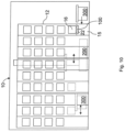
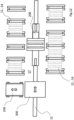
- Fig. 8 to 10 show that in Fig.1 shown storage system in a side view, a top view and a front view.
- the storage system 10 has a high-bay warehouse and a control system 21 ( Fig.8 ).
- a control system 21 Fig.8 .
- storage and retrieval processes of the high-bay warehouse of the storage system 10 can be controlled and/or monitored and/or stored.
- the controller 21 is therefore set up and/or programmed to operate the storage system 10.
- the high-bay warehouse has a first row of shelves 12, a second row of shelves 13 and a third row of shelves 14 arranged next to one another.
- the first row of shelves 12 and the third row of shelves 14 are each designed as double rows of shelves, i.e. each has a plurality of two storage locations 19 one behind the other.
- the second row of shelves 13 is designed as a quadruple row of shelves, i.e. each has four storage locations 19 one behind the other.
- the aisles 17 each have a handling movement path 20 running horizontally along the aisle 17.
- the handling movement path 20 is designed as a rail-bound or track-guided handling movement path and for this purpose has a central guide rail 11 which has flanks on both sides extending vertically upwards, on which wheels of conveyors of the storage system 10 can roll.
- the conveyors can therefore be moved linearly along the direction of the aisle 17.
- a direction running along the handling movement path 20 and thus the guide rail 11 is referred to below as the horizontal picking direction.
- a direction running perpendicular to this, extending up and down the high-bay rack is referred to as the vertical picking direction.
- a direction at right angles to the horizontal and vertical picking direction is referred to as the retrieval direction.
- the retrieval direction therefore runs at right angles to an extension of the rows of shelves from the front to the back of the high-bay warehouse, i.e. at right angles through the rows of shelves.
- the high-bay warehouse of the storage system 10 has a pre-zone with an exit 15.
- the pre-zone serves as a handling area for piece goods 16 to be stored in the high-bay warehouse. It is conceivable to provide several of the exits 15 in the pre-zone.
- the exit 15 has a movement path or exit movement path 22 on which the piece goods 16 can be conveyed for storage and removal.
- the extension movement path 22 extends over or is preferably formed by at least a plurality of storage location movement paths 25 of individual storage locations 19 and at least one bridge movement path 311 of a handling bridge 304 of a third conveyor 300, 300/1, 300/2 of the high-bay warehouse.
- a picking movement path 18 is formed for storing or retrieving one of the piece goods 16 by means of a picking bridge 206 of a lifting device 210 of a second conveyor 200, 200/1, 200/2 of the high-bay warehouse.
- the picking movement path 18 is composed of a bridge movement path 207, the picking bridge 206 and a storage location movement path 25 of the corresponding storage location 19 on which the piece goods 16 can be stored.
- the storage system 10 In addition to the second conveyor 200, 200/1, 200/2 and the third conveyor 300, 300/1, 300/2, the storage system 10 also has a first conveyor 100, 100/1, 100/2.
- the storage system 10 or high-bay warehouse shown as an example has a first shelf level R1, a second shelf level R2 arranged above it, a third shelf level R3 arranged above it and a fourth shelf level R4 as the topmost one. In principle, more than four shelf levels can also be provided.
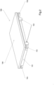
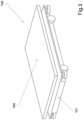
- the first funding 100, 100/1, 100/2 is explained below using the Fig. 2 to 4 explained in more detail, each showing a three-dimensional view of the first conveyor from the front and top.
- the first conveyor 100, 100/1, 100/2 of the storage system 10 has a plurality of satellite conveyors, according to the representation of the figures, for example a first satellite conveyor 100/1 and a second satellite conveyor 100/2.
- the number of satellite conveyors is variable.
- the Fig. 2 to 4 show an example of one of the satellite conveyors.
- This has a vehicle substructure 101 with drive wheels 102 and guide wheels 103.
- a lifting table 104 is arranged, which as in Fig.3 obviously vertically upwards, i.e.
- the lifting table 104 is shown in its lifting position together with a schematically illustrated pallet on which one of the piece goods 16 is located.
- the movement paths mentioned have a U-shaped profile, on the side flanks of which the guide wheels 103 can roll to keep the first conveyor 100, 100/1, 100/2 in the track.
- the first conveyors 100, 100/1, 100/2 shown are therefore a large number of discontinuous conveyors designed as under-run tractors.
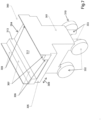
- Fig.5 and 6 show an example of a picking conveyor of the second conveyor 200, 200/1, 200/2.
- the storage system 10 has, for example, a first picking conveyor 200/1 and a second picking conveyor 200/2, each of which travels along one of the remaining aisles 17 between the rows of shelves 12 to 14 along the corresponding handling movement path 20 in the horizontal picking direction.
- the Fig.5 and 6 The picking conveyor 200, 200/1, 200/2 shown is explained in more detail below.
- the picking conveyor 200, 200/1, 200/2 has a Vehicle substructure 201.
- the vehicle substructure 201 has wheels 202 as a drive and guide wheels 203 arranged centrally inside.
- the guide wheels 203 can roll on the flanks of the running rail 11 to provide a track.
- the guide wheels 203 are also designed to form a friction drive by means of a corresponding contact pressure.
- the wheels 202 that work on the ground can also be designed as drive wheels.
- the picking conveyor 200, 200/1, 200/2 has a vertical rod 205. This extends vertically upwards, i.e. along the vertical picking direction.
- the vertical rod 205 serves as a bearing for the lifting device 210.
- the lifting device 210 has a U-shaped overhang 211, which can be displaced along the longitudinal direction of the vertical rod 205 along the vertical picking direction by means of a drive (not shown in detail).
- the lifting device 210 can therefore be displaced two-dimensionally in the horizontal picking direction by means of the vehicle substructure 201 and the overhang 211 in cooperation with the vertical rod 205.
- the lifting device 210 has a plate 212, which forms a lifting table.
- Rails 213 are attached to both sides of the plate 212 and can serve as guides for the guide wheels 103 of the first satellite conveyor 100, 100/1, 100/2.
- the rails 213 can serve as a support for setting down the piece goods 16 or a pallet on which the piece goods 16 is stored, in particular if the first satellite conveyor 100, 100/1, 100/2 is not conveyed together with the lifting device 210.
- the rails 213 and the plate 212 form a U-shaped profile, which in turn has the bridge movement path 207. Within the bridge movement path 207, the first satellite conveyor 100, 100/1, 100/2 can be displaced along the retrieval direction.
- the picking bridge 206 and the bridge movement path 207 are thus aligned vertically to a direction of travel of the first picking conveyor 200, 200/1, 200/2 and also vertically to a lifting direction of the lifting device 210, i.e. the vertical picking direction.
- the lifting device 210 has flanges 214. By means of the flanges 214, a piece of goods 216 located on the lifting device 210 can be additionally protected against slipping or accidental displacement during conveyance.
- Fig.7 shows a three-dimensional view of a third conveyor 300, 300/1, 300/2 of the storage system 10 from the front at an angle from above.
- the third conveyor 300 comprises at least one, preferably a plurality of handling conveyors 300, 300/1, 300/2, in the example shown in the figures a first handling conveyor 300/1 and a second handling conveyor 300/2. These also travel along the handling movement path 20, i.e. use its travel rail 11 together with the second conveyor 200, 200/1, 200/2.
- a first picking conveyor 200, 200/1, 200/2 and a second handling conveyor 300, 300/1, 300/2 are provided in each lane 17.
- the handling conveyor 300, 300/1, 300/2 shown has a vehicle substructure 301 with drive wheels 302 and guide wheels 303 that roll perpendicular to these.
- the guide wheels 303 can roll on the shared rail 11 of the respective handling movement path 20 of the respective aisle 17 in a similar way to the guide wheels 203 of the picking conveyor 200, 200/1, 200/2, providing track guidance. Analogously, these can either be used only for track guidance and/or for drive. If necessary, a drive of the drive wheels 302 can then be dispensed with or an additional drive can be provided.
- the third conveyor 300, 300/1, 300/2 has a plate 305.
- the drive wheels 102 of the first satellite conveyor 100, 100/2, 100/2 can roll on the plate 305.
- a first L-profile 306 is arranged on both sides of the plate 305.
- the first L-profiles 306 are mounted on a base of a U-profile 308.
- the U-profile 308 is in turn mounted on the plate 305 of the first handling conveyor 300, 300/1, 300/2.
- a second L-profile 307 is mounted on both sides of the inner sides of the flanks of the U-profile 308.
- a step is formed on both sides within the U-profile 308, on the vertical flanks of which the guide wheels 103 of the first satellite guide means 100, 100/1, 100/2 roll and on the horizontal flanks of which, which are formed by the second L-profiles 307, the piece goods 16 can be placed.
- the step is higher than a height of the first satellite conveyor means 100, 100/1, 100/2 with the lifting table 104 lowered. This means that piece goods 16 stored on the step can be driven under.
- the vehicle substructure 301 has a chassis 310 with the drive wheels 302 and guide wheels 303, which enables a floor-bound movement of the third handling conveyor 300, 300/1, 300/2 along a direction of travel 309.
- the direction of travel 309 of the chassis 310 of the handling conveyor 300, 300/1, 300/2 corresponds to the horizontal picking direction.
- the bridge movement path 311 formed by the L-profiles 306 and 307 and the U-profile 308, i.e. the handling bridge 304, is aligned at a right angle to the direction of travel 309 and thus to the horizontal picking direction.
- the L-profiles 306 and 307 as well as the U-profile 308 form a guide rail 313 of the bridge movement path 311.
- the guide wheels 103 can be attached to the guide rail 313. of the satellite conveyor 100, 100/1, 100/2.
- Each of the storage locations 19, the picking bridge 206 and the handling bridge 304 are designed analogously, i.e. each has an analogously designed movement path, which is aligned in the retrieval direction, i.e. preferably at a right angle to the horizontal picking direction.
- the piece goods A1 are located in the 3rd row of shelves 14 and the piece goods A2 and A3 are located in the second row of shelves 13 and are to be retrieved from there, i.e. conveyed in a desired order to the exit 15 of the high-bay warehouse of the storage system 10.
- A1, A2, A3 are transported using the conveyors 100, 100/1, 100/2, 200, 200/1, 200/2, 300, 300/1, 300/1 of the high-bay warehouse of the storage system 10.
- A1, A2, A3 are arranged on pallets in different storage locations 19 on different shelf levels R2 to R4 if necessary.
- the first shelf level R1 is used exclusively as a buffer level, i.e. it only has buffer storage locations that can be constructed in a similar way to the storage locations 19 of the other shelf levels or are preferred. In principle, however, any free storage location 19 in the storage system 10 can be used as a buffer storage location.
- A1 is stored in the second shelf level R2 in the third shelf row 14, A2 in the fourth shelf level R4 of the second shelf row 13 and A3 in the third shelf level R3 of the second shelf row 13.
- the following explains how these can be transported in the order A1, A2, A3 along the shortest route to the destination point, i.e. to exit 15.
- the first satellite conveyor 100/1 is located on the lifting device 210 of the first picking conveyor 200/1.
- the lifting device is moved to the storage location 19 of A1.
- the second satellite conveyor 100/2 is located on the lifting device 210 of the second picking conveyor 200/2, which is conveyed to the storage location 19 of A3. Since A1 is stored at the very end of the third row of shelves 14, the first handling conveyor 300/1 leaves the corresponding aisle 17 and releases it for the first picking conveyor 200/1.
- the second handling conveyor 300/2 is located within the aisle 17, since A3 is stored approximately in the middle of the second row of shelves 13, but moves in such a way that a collision can be safely avoided. Then the first satellite conveyor 100/1 and the second satellite conveyor 100/2 leave the respective pick bridge 206 and drive under A1 and A3.
- the first satellite conveyor 100/1 and the second satellite conveyor After driving under A1 and A3, these are lifted by the first satellite conveyor 100/1 and the second satellite conveyor by means of the lifting tables. 100/2 and conveyed along the picking movement paths 18 thus formed to the corresponding picking bridge 206.
- the first picking conveyor 200/1 then lowers its lifting table together with the first satellite conveyor 100/1 and A1 to the first shelf level R1, whereby the second handling conveyor 300/2 has already formed the exit movement path 22 within the aisle 17.
- the second picking conveyor 200/2 or the picking bridge 206 together with the second satellite conveyor 100/2 and A3 also move to the first shelf level R1 in the same row of shelves in which A3 was previously stored.
- the first satellite conveyor 100/1 then leaves the lifting device of the first picking conveyor 200/1 with A1 and travels along the exit movement path 22 of the first shelf level R1 via the second handling conveyor 300/2 towards exit 15.
- the first satellite conveyor 100/1 therefore travels with A1 along the exit movement path 22 towards the second handling conveyor 300/2.
- the first picking conveyor 200/1 is no longer required for this task.
- the first picking conveyor 200/1 can already begin to fulfill another task of the storage system 10 or the high-bay warehouse.
- the first handling conveyor 300/1 shifts and now bridges the aisle 17 remaining between the second row of shelves 13 and the third row of shelves 14, thereby extending the exit movement path 22 through the entire high-bay warehouse.
- the second satellite conveyor 100/2 after having lowered it again, leaves A3 in the first shelf level R1 of the second row of shelves 13 and moves in an empty state, i.e. without pallet and/or piece goods 16, onto the lifting device 210 or the picking bridge 206 of the second handling conveyor 300/2.
- the second handling conveyor 300/2 then travels in its lane 17 and simultaneously lifts the picking bridge 206 together with the second satellite conveyor 100/2 to the storage location 19 where A2 is stored, i.e. to the fourth shelf level R4 of the second row of shelves 13.
- the first satellite conveyor 100/1 advantageously traverses the storage system via the second handling conveyor 300/2, i.e. moves along the exit movement path 22 to the exit 15.
- the first satellite conveyor 100/1 lowers its lifting table 104 and thus makes A1 available on the exit 15.
- the second satellite conveyor 100/2 takes over A2 in the second row of shelves 13 and moves A2 along the picking movement path 18 thus formed to the picking bridge 206 of the second picking conveyor 200/2.
- the empty first satellite conveyor 100/1 which has just parked A1 at the destination, leaves the exit 15 again along the exit movement path 22 via the second handling conveyor 300/2 and travels to the second row of shelves 13.
- the second picking conveyor 200/2 moves along the handling movement path 20 in the direction of the extension movement path 22, while simultaneously lowering its lifting device 210 into the first shelf level R1.
- the first satellite conveyor 100/1 is moved back into the second row of shelves 13, i.e. over the first handling conveyor 300/1, i.e. over the corresponding aisle 17.
- the second handling conveyor 300/2 deviates, leaves the aisle 17 to make room for the second picking conveyor 200/2 between the first row of shelves 12 and the second row of shelves 13.
- the second picking conveyor 200/2 has meanwhile conveyed the second satellite conveyor 100/2 together with A2 to the exit movement path 22.
- the exit movement path 22 is now completed by the second picking conveyor 200/2 using the picking bridge 206 instead of one of the first or second handling conveyors 300/1, 300/2.
- the first handling conveyor 300/1 has meanwhile conveyed the empty first satellite conveyor 100/1 in the aisle 17 remaining between the second row of shelves 13 and the third row of shelves 14 to a line on which A3 is buffered, i.e. on a buffer storage location 19 of the first shelf level R1.
- a line can be understood as a row of storage locations 19 extending across the aisles 17, i.e. in the retrieval direction, and/or a movement path completed by a bridge, which runs parallel to the exit movement path, in particular in the same shelf level as the exit movement path, and/or a buffer movement path.
- the second satellite conveyor 100/2 has delivered and parked A2 via the exit movement path 22 to the exit 15.
- the second picking conveyor 200/2 is also no longer required in the further course of this work cycle and, if necessary, leaves the storage system 10 or the part of the storage system 10 required for the work cycle and can devote itself to further picking processes if necessary.
- the second handling conveyor 300/2 bridges the first row of shelves 12 and the second row of shelves 13 and again forms the exit movement path 22.
- the empty first satellite conveyor 100/1 now travels along this back to the first shelf level R1 with the aim of driving under A3.
- the empty second satellite conveyor 100/2 moves from the exit 15 along the exit movement path 22 over the second handling conveyor 300/2.
- the second picking conveyor 200/2 has deviated or is starting other tasks.
- the first satellite conveyor 100/1 drives under A3 as intended and takes A3 with it.
- the second satellite conveyor 100/2 crosses the aisle 17 over the second handling conveyor 300/2 and drives into the second row of shelves 13.
- the second handling conveyor 300/2 moves after being released by the second satellite conveyor 100/2, i.e. after it has been driven over, to the buffer storage location 19 in the first shelf level R1, where A3 is stored.
- the first handling conveyor 300/1 moves back in order to form the exit movement path 22 again and to pick up the second satellite conveyor 100/2 moving on it in the second row of shelves 13.
- the first picking conveyor 200/1 and the second picking conveyor 200/2 are advantageously no longer required.
- the remaining retrieval process is continued only by means of the first satellite conveyor 100/1, the second satellite conveyor 100/2, the first handling conveyor 300/1 and/or the second handling conveyor 300/2. This allows the throughput to be increased significantly.
- the first satellite conveyor 100/1 moves together with A3 onto the second handling conveyor 300/2 and the empty second satellite conveyor 100/2 moves onto the first handling conveyor 300/1.
- the first handling conveyor 300/1 is now moved together with the first satellite conveyor 100/1 to a further buffer storage location 19.
- the second handling conveyor 300/2 delivers the first satellite conveyor 100/1 together with A3 to the exit movement path 22 or completes it.
- the first satellite conveyor 100/1 then leaves the second handling conveyor 300/2 along the exit movement path 22 in the direction of the exit 15 and thus delivers A3 to the exit 15.
- the first satellite conveyor 100/1 then lowers A3 and travels along the exit movement path 22 back to the first shelf level R1 and is available there for the next work cycle.
- A1, A2, A3 are provided in the prescribed order on the shortest route through the conveyors 100, 100/1, 100/2, 200, 200/1, 200/2, 300, 300/1, 300/2 of the high-bay warehouse of the storage system 10 on the exit 15 and can be taken over from there by means of conveyors not shown in detail, e.g. by forklifts or similar.
- the work cycle described is an example and can also be used for storage in the reverse order.
- the number of rows of shelves shown, their height, width and depth are examples.
- At least one movement path running along the horizontal picking direction is formed at least with the aid of the picking bridge 206 of the second conveyor 200, 200/1, 200/2 and/or by means of the handling bridge of the third conveyor 300, 300/1, 300/2, in particular the picking movement path 20, the extension movement path 22 and/or a buffer movement path for optionally buffering the General cargo 16.
- the movement paths created by bridging all run along the retrieval direction.
- the buffer movement path runs within the same plane as the exit movement path and parallel to it.
- at least one of the aisles 17 is bridged in such a way that the exit movement path 22 is thereby created, wherein the piece goods 16 can be conveyed on the exit movement path 22 between the exit 15 and the rest of the storage system 10.
- the exit movement path 22 can optionally be formed using the third conveying means 300, 300/1, 300/2.
- the aisles 17 can be connected at any point to form movement paths along the retrieval direction, e.g. for empty transports of the first conveyor 100, 100/1, 100/2. This advantageously moves along the retrieval direction within the first shelf level R1 regardless of the storage status of the first shelf level R1, since any piece goods 16 present in corresponding buffer storage locations or storage locations 19 can be driven under as desired.
- the first conveyor 100, 100/1, 100/2 can advantageously move to any storage location 19 of the first shelf level R1 using the handling bridges 304 and/or the picking bridges 206 of the third conveyor 300, 300/1, 300/2 or the second conveyor 200, 200/1, 200/2.
- This allows very efficient buffering and/or picking of the piece goods 16.
- the first conveyor 100, 100/1, 100/2 is moved in the retrieval direction, as described, regardless of whether the corresponding buffer storage locations or storage locations 19 are occupied, since piece goods 16 stored there can be driven under and thus passed.
- a shift in the horizontal picking direction can be carried out by means of the bridges, i.e. the picking bridge 206 and/or the handling bridge 304.
- first shelf level R1 can optionally be served by the first conveyor 100, 100/1, 100/2 and the third conveyor 300, 300/1, 300/2 without the aid of the second conveyor 200, 200/1, 200/2. It is clear that with regard to the first shelf level R1, a redundant possibility for conveying the piece goods 16 and thus in particular for buffering them has been created, namely by providing the second conveyor 200, 200/1, 200/2 and the third conveyor 300, 300/1, 300/2, which each move together on one of the handling movement paths 20.
- the storage system 10 therefore has at least one redundantly operable shelf level, in this case the first shelf level R1.
- any of the shelf levels as a buffer level on which the third conveyor 300, 300/1, 300/2 can move along the retrieval direction and the horizontal picking direction.
- the handling movement path 20 it is also possible for the handling movement path 20 to have different rails 11, e.g. one for the second conveyor 200, 200/1, 200/2 and one for the third conveyor 300, 300/1, 300/2, whereby these can be arranged parallel and spatially spaced apart from one another.
- the second conveyor 200, 200/1, 200/2 can be operated on a lowest level and, for example, the third conveyor 300, 300/1, 300/2 on a top or removal or buffer level.
- the guide rail 11 for the third conveyor 300, 300/1, 300/2 can be implemented using recessed grooves, for example.
- it is advantageous to use a middle shelf level as a buffer level so that it can be controlled even faster and more efficiently, since a travel path in the vertical picking direction is possible on both sides towards the buffer level and can therefore be significantly reduced.
- the control system 21 can be wired, at least partially wired, via radio links and/or similar devices for data exchange. In addition, it can have corresponding computing means for calculating positions and/or travel paths. In particular, it can coordinate all movements of the conveyors present in the storage system 10.
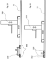
- Fig. 11 shows a side view of the travel rail 11 of the handling movement path 20 together with the first conveyor 100, 100/1, 100/2 and the second conveyor 200, 200/1, 200/2.
- the mobility of the second conveyor 200, 200/1, 200/2 along the horizontal picking direction and the vertical picking direction is indicated by double arrows.
- the first conveyor 100, 100/1, 100/2 is located on the third conveyor 300, 300/1, 300/2.
- the dashed line indicates that the third conveyor 300, 300/1, 300/2 can be moved from a working position 23, which is in Fig. 11 shown in bold, into a rest position 24, which is Fig. 11 shown in dashed lines, can be adjusted and back again.
- the third conveyor 300, 300/1, 300/2 has a reduced space requirement, so that as little as possible, or possibly no additional space, is required at the ends of the aisles 17. This space is therefore available to the second conveyor 200, 200/1, 200/2 if required.
- the installation is carried out by a suitable drive, in particular its own drive and/or joint mechanism and/or a positive guide, which intervenes when an end of the aisle is reached and adjusts the first conveyor.
- Fig. 12 shows a top view of the Fig. 11 illustrated handling movement path 20 together with the travel rail 11 and two of the rows of shelves 12 to 14, which form the aisle 17. Double arrows symbolize, on the one hand, the mobility of the third conveyor 300, 300/1, 300/2 along the horizontal picking direction and, on the other hand, the orthogonal displaceability of the first conveyor 100, 100/1, 100/2 along the retrieval direction.
- the Fig. 13 to 20 show different possibilities for establishing the working position 23 and rest position 24 of the third conveyor 300, 300/1, 300/2.
- Fig. 13 shows the third conveyor 300, 300/1, 300/2 in the working position 23.
- Fig. 14 the rest position 24.
- the vehicle substructure 301 has a recess, i.e. a comparatively short wheelbase, wherein the handling bridge 304 can be raised relative to the vehicle substructure 301 by means of a suitable lifting device such that the handling bridge 304 can be raised over a spatial extension of the vehicle substructure 201 of the second conveyor 200, 200/1, 200/2.
- the vehicle substructure 201 can thus be moved in a space-saving manner under the recess of the third conveyor 300, 300/1, 300/2. This advantageously saves space at the end of the aisle 17.
- Fig. 15 shows another embodiment of the third conveyor 300, 300/1, 300/2 in the working position 23.
- Fig. 16 this in its rest position 24.
- a part of the third conveyor 300, 300/1, 300/2 or the plate 305 is divided into two and can be folded vertically upwards.
- the plate 305 is designed in such a way that a first part carries the handling bridge 304 and a second part has an additional chassis with which the third conveyor 300, 300/1, 300/2 can also be moved in the rest position 24.
- the smaller remaining part of the foldable plate 305 has two axes and the larger part of the plate 305 that accommodates the handling bridge 304 has one axis.
- Fig. 17 shows another embodiment of a third conveyor 300, 300/1, 300/2 in the working position 23.
- Fig. 18 this in its rest position 24.
- the plate 305 of the third conveyor 300, 300/1, 300/2 is segmented into a plurality of strips that can be rolled up, as in Fig. 18
- the third conveyor 300, 300/1, 300/2 can be moved as shown in Fig. 18 shown, between its working position 23 and its rest position 24.
- Fig. 19 shows a further third conveyor 300, 300/1, 300/2 in its working position 23.
- Fig. 20 shows this in its rest position 24.
- the third conveyor 300, 300/1, 300/2 has a two-part plate 305 or is as such divided into two parts, thus having two vehicle substructures 301, each of which has its own drive wheels 302 and guide wheels 303, thus its own chassis 310.
- the third conveyor means 300, 300/1, 300/2 shown are particularly compact and can be bridged by the handling bridge 304 in the working position 23.
- the handling bridge 304 can be lifted off the two-part plate 305 so that the individual parts of the third conveyor means 300, 300/1, 300/2 can be moved towards one another in the direction of the handling movement path 20 or on this in the direction of the horizontal picking direction. It is clear that this saves space along the horizontal picking direction of the storage system 10 or the high-bay warehouse, so that any overhang over one end of the respective aisle 17 can be reduced or, if necessary, completely avoided, provided that the corresponding third conveyor 300, 300/1, 300/2 is not currently needed and is in a parking position at the respective end of the aisle 17.
- Fig. 21 shows four schematic representations A to D, each with an aisle 17 of a storage system 10 analogous to the storage system.
- a storage system 10 analogous to the storage system.
- the aisle 17 of the only partially shown storage system 10 has a stationary handling bridge 304.
- the stationary handling bridge 304 can be moved between the working position and the rest position.
- the handling bridge 304 can therefore remain stationary in the aisle 17, does not have to be parked at one end and can nevertheless be moved between the rest position and the working position.
- a side view of the storage system 10 is shown looking sideways into the aisle 17.
- the handling bridge 304 can be pivoted about a horizontal pivot axis extending in the longitudinal direction of the aisle 17, in particular essentially parallel to an aisle wall.
- the working position is shown in solid lines and the rest position in dashed lines.
- a plan view of the storage system 10 is shown looking from above into the aisle 17.
- the handling bridge 304 can be pivoted about a vertical pivot axis extending from bottom to top in the aisle 17, in particular essentially parallel to an aisle wall.
- the working position is shown in solid lines and the rest position in dashed lines.
- the handling bridge 304 can therefore be handled like a rotating bridge.
- a side view of the storage system 10 is shown looking sideways into the aisle 17.
- the handling bridge 304 can be moved vertically in the aisle 17, in particular essentially parallel to an aisle wall.
- the handling bridge 304 can therefore be moved either in the direction of a floor of the aisle 17 or in the direction of an upper end opposite the floor. It is also possible to provide both options for moving, with the rest position being reached at the floor or at the upper end in order to allow the second conveyor 200 to pass freely.
- the working position is shown in solid lines and the possible rest positions are shown in dashed lines.
- a side view of the storage system 10 is shown looking sideways into the aisle 17.
- the handling bridge 304 can be displaced or moved horizontally in the aisle 17, in particular essentially perpendicular to an aisle wall. When the handling bridge 304 is pushed completely into the aisle 17, it has reached the working position and can be driven over by the first conveyor 100 to cross the aisle 17. If the handling bridge 304 is displaced in the direction of a storage location 19 of the aisle 17 (not shown in more detail), it has reached its rest position and clears the aisle 17 for the second conveyor to pass through. Illustration D shows an intermediate position between the working position and the rest position.
- Fig. 21 The described possibilities for switching between the rest position and the working position can also be provided for a non-stationary handling bridge 304 or third conveyor means 300.
Landscapes
- Engineering & Computer Science (AREA)
- Mechanical Engineering (AREA)
- Warehouses Or Storage Devices (AREA)
Priority Applications (2)
| Application Number | Priority Date | Filing Date | Title |
|---|---|---|---|
| HRP20241710TT HRP20241710T1 (hr) | 2016-05-14 | 2017-05-15 | Postupak i uređaj za skladištenje komadne robe sa redovima polica koji se mogu premostiti |
| RS20241400A RS66309B1 (sr) | 2016-05-14 | 2017-05-15 | Postupak i uređaj za skladištenje komadne robe sa redovima polica koji se mogu premostiti |
Applications Claiming Priority (1)
| Application Number | Priority Date | Filing Date | Title |
|---|---|---|---|
| DE102016108992.3A DE102016108992A1 (de) | 2016-05-14 | 2016-05-14 | Verfahren und Vorrichtung zum Lagern von Stückgut mit überbrückbaren Regalreihen |
Publications (3)
| Publication Number | Publication Date |
|---|---|
| EP3243769A1 EP3243769A1 (de) | 2017-11-15 |
| EP3243769B1 true EP3243769B1 (de) | 2024-09-18 |
| EP3243769C0 EP3243769C0 (de) | 2024-09-18 |
Family
ID=58709863
Family Applications (1)
| Application Number | Title | Priority Date | Filing Date |
|---|---|---|---|
| EP17171189.8A Active EP3243769B1 (de) | 2016-05-14 | 2017-05-15 | Verfahren und vorrichtung zum lagern von stückgut mit überbrückbaren regalreihen |
Country Status (7)
| Country | Link |
|---|---|
| EP (1) | EP3243769B1 (pl) |
| DE (1) | DE102016108992A1 (pl) |
| ES (1) | ES2998027T3 (pl) |
| HR (1) | HRP20241710T1 (pl) |
| HU (1) | HUE069625T2 (pl) |
| PL (1) | PL3243769T3 (pl) |
| RS (1) | RS66309B1 (pl) |
Families Citing this family (15)
| Publication number | Priority date | Publication date | Assignee | Title |
|---|---|---|---|---|
| US11180327B2 (en) | 2017-03-29 | 2021-11-23 | Dematic Gmbh | Method for automatically stacking packages in layers on a support |
| HRP20211825T1 (hr) * | 2017-10-23 | 2022-03-04 | Jörg Föller | Postupak i tehnologija visokoregalnog skladištenja za skladištenje komadne robe pomoću ortogonalnog poprečnog skladištenja |
| CN108792400B (zh) * | 2018-07-06 | 2023-12-01 | 晋江凯燕新材料科技有限公司 | 具自动存取功能的智能仓库 |
| CN108945812B (zh) * | 2018-08-17 | 2024-04-16 | 苏州精濑光电有限公司 | 一种电子器件中转和储存设备 |
| CN110562652B (zh) * | 2019-07-30 | 2021-01-26 | 国网浙江省电力有限公司嘉兴供电公司 | 一种基于物联网的电力备件智能仓库 |
| CN110482100B (zh) * | 2019-08-12 | 2020-12-11 | 浙江睿索电子科技有限公司 | 一种智能仓储管理货架及控制方法 |
| CN111483804B (zh) * | 2020-04-24 | 2021-08-10 | 常州市新创智能科技有限公司 | 一种模具自动选取移动装置 |
| CN113335820A (zh) * | 2021-06-30 | 2021-09-03 | 广州普华灵动机器人技术有限公司 | 一种立体仓库与agv直接对接的入库及出库方法 |
| CN116280841B (zh) * | 2021-12-20 | 2026-04-17 | 北京极智嘉科技股份有限公司 | 立体仓储系统以及用于其的货架系统 |
| WO2023116446A1 (zh) * | 2021-12-20 | 2023-06-29 | 北京极智嘉科技股份有限公司 | 立体仓储系统以及用于其的货架系统和自动搬运设备 |
| CN114212362B (zh) * | 2021-12-31 | 2024-12-03 | 北京合锐赛尔电力科技股份有限公司 | 基于机器人的化学试剂存储装置及控制方法 |
| CN114988005B (zh) * | 2022-06-29 | 2024-01-05 | 山东西部智能科技有限公司 | 一种盒装物品管理系统 |
| CN115258489A (zh) * | 2022-08-03 | 2022-11-01 | 北京京东乾石科技有限公司 | 货物分播设备、系统、设备控制方法、控制器和可读介质 |
| CN115783580B (zh) * | 2022-10-24 | 2023-06-30 | 湖北凯乐仕通达科技有限公司 | 自动化存取系统及方法、自动化立体仓库 |
| CN118651541B (zh) * | 2024-07-17 | 2025-09-12 | 清华大学 | 一种非平衡状态下多级无干涉自动化大负载装卸货架 |
Family Cites Families (11)
| Publication number | Priority date | Publication date | Assignee | Title |
|---|---|---|---|---|
| IT1136819B (it) * | 1981-03-13 | 1986-09-03 | Finsider Costr Metall Cmf | Dispositivo trasportatore per un impianto di magazzinaggio |
| AT410438B (de) * | 1999-02-10 | 2003-04-25 | Ltw Lagertechnik Gmbh | Lagermagazin |
| DE202004012021U1 (de) * | 2004-07-27 | 2005-12-15 | Bellheimer Metallwerk Gmbh | Lagersystem |
| DE102006008932A1 (de) * | 2006-02-22 | 2007-08-23 | Bellheimer Metallwerk Gmbh | Lagerliftanordnung |
| DE102007016453B4 (de) * | 2007-03-30 | 2009-01-08 | SSI Schäfer Noell GmbH Lager- und Systemtechnik | Automatisiertes Kommissioniersystem mit integrierter Sortierfunktion und Verfahren zum Betreiben desselben |
| NL1033799C2 (nl) * | 2007-05-03 | 2008-11-10 | Scarabee Id B V | Systeem en werkwijze voor het opslaan van goederen. |
| DE102011115076A1 (de) | 2011-09-28 | 2013-03-28 | FAB GmbH Fördertechnik und Anlagenbau | Bewegungsvorrichtung für Transporteinheiten |
| DE102013005614A1 (de) * | 2013-04-04 | 2014-10-09 | Atlantic C Handels- Und Beratungs-Gmbh | Lager |
| EP2949605B1 (en) * | 2014-05-28 | 2017-07-05 | Dematic GmbH | Method of order fulfilling by making storage units available from a storage facility at a picking station |
| DE102014012254A1 (de) * | 2014-08-19 | 2016-02-25 | Lisa-Marie Amminger | Lager- und/oder Kommissioniersysteme |
| US9505556B2 (en) * | 2014-09-03 | 2016-11-29 | Ottos Consultants Ltd. | Storage system using lifting mechanism for collecting containers in desired sequence |
-
2016
- 2016-05-14 DE DE102016108992.3A patent/DE102016108992A1/de active Pending
-
2017
- 2017-05-15 PL PL17171189.8T patent/PL3243769T3/pl unknown
- 2017-05-15 HR HRP20241710TT patent/HRP20241710T1/hr unknown
- 2017-05-15 ES ES17171189T patent/ES2998027T3/es active Active
- 2017-05-15 RS RS20241400A patent/RS66309B1/sr unknown
- 2017-05-15 HU HUE17171189A patent/HUE069625T2/hu unknown
- 2017-05-15 EP EP17171189.8A patent/EP3243769B1/de active Active
Also Published As
| Publication number | Publication date |
|---|---|
| EP3243769A1 (de) | 2017-11-15 |
| ES2998027T3 (en) | 2025-02-18 |
| EP3243769C0 (de) | 2024-09-18 |
| HRP20241710T1 (hr) | 2025-02-14 |
| DE102016108992A1 (de) | 2017-11-16 |
| RS66309B1 (sr) | 2025-01-31 |
| PL3243769T3 (pl) | 2025-02-24 |
| HUE069625T2 (hu) | 2025-03-28 |
Similar Documents
| Publication | Publication Date | Title |
|---|---|---|
| EP3243769A1 (de) | Verfahren und vorrichtung zum lagern von stückgut mit überbrückbaren regalreihen | |
| AT512339B1 (de) | Regallagersystem und verfahren zum betreiben desselben | |
| EP3429947B1 (de) | System aus einem regalbediengerät und einem transport- und übergabesystem zum ein- und auslagern oder umlagern von standardcontainern | |
| EP2709933B1 (de) | Regallagersystem | |
| EP2673217B1 (de) | Regallagersystem und verfahren zum betreiben desselben | |
| EP2607292B1 (de) | System zum Transport von auf Hilfsmitteln angeordneten Gütern | |
| EP0776291B1 (de) | Verfahren und vorrichtung zum umschlagen von ladung | |
| EP3283418B1 (de) | Verfahren und container-umschlaganlage zum ein- und auslagern von containern in containerlagern | |
| EP0654425A1 (de) | Verfahren zum Ein- oder Auslagern bzw. Umstapeln von Trägern für Fördergut in bzw. aus einem mehretagigen Lager und eine Vorrichtung zur Durchführung des Verfahrens | |
| DE102014003451A1 (de) | Reagalbediengerät mit hochgesetzter Fahrschiene | |
| EP0589844B1 (de) | Hochleistungs-Blocklager mit Mitteln zum Ein- und Auslagern von Lagergut | |
| EP3749594A1 (de) | Kommissioniereinrichtung | |
| EP1028074B1 (de) | Lagermagazin | |
| EP0096784A1 (de) | Vollautomatisches Regallager | |
| EP3473562B1 (de) | Verfahren und hochregallagertechnologie zum lagern von stückgut mittels orthogonaler quereinlagerung | |
| DE102019134776B3 (de) | Verschieberegalanordnung und Verfahren zum Betreiben der Verschieberegalanordnung | |
| AT528068B1 (de) | Vorrichtung zum Bereitstellen von Auftragswaren in einer Reihenfolge mit kompaktem Aufbau und Kommissioniersystem und Betriebsverfahren dazu | |
| DE102023107593A1 (de) | Lager-System und Verfahren zum Betreiben eines Lager-Systems | |
| EP3883866A1 (de) | Flächenlager | |
| EP4371907A1 (de) | Shuttle-system und verfahren zum betreiben eines shuttle-systems | |
| WO2024211953A2 (de) | Transportfahrzeug, übergabestation, arbeitsstation für ein optimiertes beladen von ladehilfsmitteln und kommissioniersystem | |
| AT527085A2 (de) | Transportfahrzeug, Übergabestation, Arbeitsstation für ein optimiertes Beladen von Ladehilfsmitteln und Kommissioniersystem | |
| DE2818190A1 (de) | Verfahren zum sortieren, weitergeben und gegebenenfalls lagern beliebiger gueter und lager hierzu | |
| DE29504727U1 (de) | Fahrerloses Transportsystem | |
| DE2034834A1 (de) | Kombiniertes Lagerbedienungsgerat |
Legal Events
| Date | Code | Title | Description |
|---|---|---|---|
| REG | Reference to a national code |
Ref country code: HR Ref legal event code: TUEP Ref document number: P20241710T Country of ref document: HR |
|
| PUAI | Public reference made under article 153(3) epc to a published international application that has entered the european phase |
Free format text: ORIGINAL CODE: 0009012 |
|
| STAA | Information on the status of an ep patent application or granted ep patent |
Free format text: STATUS: THE APPLICATION HAS BEEN PUBLISHED |
|
| AK | Designated contracting states |
Kind code of ref document: A1 Designated state(s): AL AT BE BG CH CY CZ DE DK EE ES FI FR GB GR HR HU IE IS IT LI LT LU LV MC MK MT NL NO PL PT RO RS SE SI SK SM TR |
|
| AX | Request for extension of the european patent |
Extension state: BA ME |
|
| STAA | Information on the status of an ep patent application or granted ep patent |
Free format text: STATUS: REQUEST FOR EXAMINATION WAS MADE |
|
| 17P | Request for examination filed |
Effective date: 20180515 |
|
| RBV | Designated contracting states (corrected) |
Designated state(s): AL AT BE BG CH CY CZ DE DK EE ES FI FR GB GR HR HU IE IS IT LI LT LU LV MC MK MT NL NO PL PT RO RS SE SI SK SM TR |
|
| STAA | Information on the status of an ep patent application or granted ep patent |
Free format text: STATUS: EXAMINATION IS IN PROGRESS |
|
| 17Q | First examination report despatched |
Effective date: 20181019 |
|
| GRAP | Despatch of communication of intention to grant a patent |
Free format text: ORIGINAL CODE: EPIDOSNIGR1 |
|
| STAA | Information on the status of an ep patent application or granted ep patent |
Free format text: STATUS: GRANT OF PATENT IS INTENDED |
|
| INTG | Intention to grant announced |
Effective date: 20240411 |
|
| GRAS | Grant fee paid |
Free format text: ORIGINAL CODE: EPIDOSNIGR3 |
|
| GRAA | (expected) grant |
Free format text: ORIGINAL CODE: 0009210 |
|
| STAA | Information on the status of an ep patent application or granted ep patent |
Free format text: STATUS: THE PATENT HAS BEEN GRANTED |
|
| AK | Designated contracting states |
Kind code of ref document: B1 Designated state(s): AL AT BE BG CH CY CZ DE DK EE ES FI FR GB GR HR HU IE IS IT LI LT LU LV MC MK MT NL NO PL PT RO RS SE SI SK SM TR |
|
| REG | Reference to a national code |
Ref country code: GB Ref legal event code: FG4D Free format text: NOT ENGLISH |
|
| REG | Reference to a national code |
Ref country code: CH Ref legal event code: EP |
|
| REG | Reference to a national code |
Ref country code: DE Ref legal event code: R096 Ref document number: 502017016433 Country of ref document: DE |
|
| REG | Reference to a national code |
Ref country code: IE Ref legal event code: FG4D Free format text: LANGUAGE OF EP DOCUMENT: GERMAN |
|
| U01 | Request for unitary effect filed |
Effective date: 20241009 |
|
| U07 | Unitary effect registered |
Designated state(s): AT BE BG DE DK EE FI FR IT LT LU LV MT NL PT RO SE SI Effective date: 20241029 |
|
| PG25 | Lapsed in a contracting state [announced via postgrant information from national office to epo] |
Ref country code: GR Free format text: LAPSE BECAUSE OF FAILURE TO SUBMIT A TRANSLATION OF THE DESCRIPTION OR TO PAY THE FEE WITHIN THE PRESCRIBED TIME-LIMIT Effective date: 20241219 |
|
| PG25 | Lapsed in a contracting state [announced via postgrant information from national office to epo] |
Ref country code: GR Free format text: LAPSE BECAUSE OF FAILURE TO SUBMIT A TRANSLATION OF THE DESCRIPTION OR TO PAY THE FEE WITHIN THE PRESCRIBED TIME-LIMIT Effective date: 20241219 |
|
| REG | Reference to a national code |
Ref country code: SK Ref legal event code: T3 Ref document number: E 45539 Country of ref document: SK |
|
| REG | Reference to a national code |
Ref country code: HR Ref legal event code: T1PR Ref document number: P20241710 Country of ref document: HR |
|
| REG | Reference to a national code |
Ref country code: ES Ref legal event code: FG2A Ref document number: 2998027 Country of ref document: ES Kind code of ref document: T3 Effective date: 20250218 |
|
| REG | Reference to a national code |
Ref country code: HU Ref legal event code: AG4A Ref document number: E069625 Country of ref document: HU |
|
| PG25 | Lapsed in a contracting state [announced via postgrant information from national office to epo] |
Ref country code: IS Free format text: LAPSE BECAUSE OF FAILURE TO SUBMIT A TRANSLATION OF THE DESCRIPTION OR TO PAY THE FEE WITHIN THE PRESCRIBED TIME-LIMIT Effective date: 20250118 |
|
| PG25 | Lapsed in a contracting state [announced via postgrant information from national office to epo] |
Ref country code: SM Free format text: LAPSE BECAUSE OF FAILURE TO SUBMIT A TRANSLATION OF THE DESCRIPTION OR TO PAY THE FEE WITHIN THE PRESCRIBED TIME-LIMIT Effective date: 20240918 |
|
| REG | Reference to a national code |
Ref country code: HR Ref legal event code: ODRP Ref document number: P20241710 Country of ref document: HR Payment date: 20250512 Year of fee payment: 9 |
|
| U20 | Renewal fee for the european patent with unitary effect paid |
Year of fee payment: 9 Effective date: 20250520 |
|
| PGFP | Annual fee paid to national office [announced via postgrant information from national office to epo] |
Ref country code: PL Payment date: 20250508 Year of fee payment: 9 |
|
| PGFP | Annual fee paid to national office [announced via postgrant information from national office to epo] |
Ref country code: GB Payment date: 20250522 Year of fee payment: 9 Ref country code: ES Payment date: 20250616 Year of fee payment: 9 |
|
| PGFP | Annual fee paid to national office [announced via postgrant information from national office to epo] |
Ref country code: RS Payment date: 20250508 Year of fee payment: 9 Ref country code: NO Payment date: 20250520 Year of fee payment: 9 |
|
| PGFP | Annual fee paid to national office [announced via postgrant information from national office to epo] |
Ref country code: HR Payment date: 20250512 Year of fee payment: 9 |
|
| PGFP | Annual fee paid to national office [announced via postgrant information from national office to epo] |
Ref country code: HU Payment date: 20250606 Year of fee payment: 9 |
|
| PGFP | Annual fee paid to national office [announced via postgrant information from national office to epo] |
Ref country code: CH Payment date: 20250601 Year of fee payment: 9 |
|
| PGFP | Annual fee paid to national office [announced via postgrant information from national office to epo] |
Ref country code: SK Payment date: 20250513 Year of fee payment: 9 |
|
| PLBE | No opposition filed within time limit |
Free format text: ORIGINAL CODE: 0009261 |
|
| STAA | Information on the status of an ep patent application or granted ep patent |
Free format text: STATUS: NO OPPOSITION FILED WITHIN TIME LIMIT |
|
| PGFP | Annual fee paid to national office [announced via postgrant information from national office to epo] |
Ref country code: CZ Payment date: 20250507 Year of fee payment: 9 |
|
| PGFP | Annual fee paid to national office [announced via postgrant information from national office to epo] |
Ref country code: IE Payment date: 20250522 Year of fee payment: 9 |
|
| 26N | No opposition filed |
Effective date: 20250619 |
|
| PG25 | Lapsed in a contracting state [announced via postgrant information from national office to epo] |
Ref country code: MC Free format text: LAPSE BECAUSE OF FAILURE TO SUBMIT A TRANSLATION OF THE DESCRIPTION OR TO PAY THE FEE WITHIN THE PRESCRIBED TIME-LIMIT Effective date: 20240918 |