EP3242122B1 - Sampling apparatus - Google Patents
Sampling apparatus Download PDFInfo
- Publication number
- EP3242122B1 EP3242122B1 EP15875165.1A EP15875165A EP3242122B1 EP 3242122 B1 EP3242122 B1 EP 3242122B1 EP 15875165 A EP15875165 A EP 15875165A EP 3242122 B1 EP3242122 B1 EP 3242122B1
- Authority
- EP
- European Patent Office
- Prior art keywords
- gas
- sampling device
- sample
- wall
- guide
- Prior art date
- Legal status (The legal status is an assumption and is not a legal conclusion. Google has not performed a legal analysis and makes no representation as to the accuracy of the status listed.)
- Active
Links
Images
Classifications
-
- G—PHYSICS
- G01—MEASURING; TESTING
- G01N—INVESTIGATING OR ANALYSING MATERIALS BY DETERMINING THEIR CHEMICAL OR PHYSICAL PROPERTIES
- G01N1/00—Sampling; Preparing specimens for investigation
- G01N1/02—Devices for withdrawing samples
- G01N1/22—Devices for withdrawing samples in the gaseous state
- G01N1/24—Suction devices
-
- G—PHYSICS
- G01—MEASURING; TESTING
- G01N—INVESTIGATING OR ANALYSING MATERIALS BY DETERMINING THEIR CHEMICAL OR PHYSICAL PROPERTIES
- G01N1/00—Sampling; Preparing specimens for investigation
- G01N1/02—Devices for withdrawing samples
- G01N1/22—Devices for withdrawing samples in the gaseous state
- G01N1/2202—Devices for withdrawing samples in the gaseous state involving separation of sample components during sampling
- G01N1/2211—Devices for withdrawing samples in the gaseous state involving separation of sample components during sampling with cyclones
-
- G—PHYSICS
- G01—MEASURING; TESTING
- G01N—INVESTIGATING OR ANALYSING MATERIALS BY DETERMINING THEIR CHEMICAL OR PHYSICAL PROPERTIES
- G01N30/00—Investigating or analysing materials by separation into components using adsorption, absorption or similar phenomena or using ion-exchange, e.g. chromatography or field flow fractionation
- G01N30/02—Column chromatography
- G01N30/26—Conditioning of the fluid carrier; Flow patterns
- G01N30/28—Control of physical parameters of the fluid carrier
- G01N30/30—Control of physical parameters of the fluid carrier of temperature
Definitions
- the present application relates to a detection system, and in particular, to a tornado type sampling device having an amplified collection function on gas-borne substance, such as organic chemicals that present as vapors in air or liberated as vapors from condensed phases such as particles or solutions or surface contamination (that is: VOCs, or Semi-VOCs, or surface contamination) and a gas curtain guide.
- gas-borne substance such as organic chemicals that present as vapors in air or liberated as vapors from condensed phases such as particles or solutions or surface contamination (that is: VOCs, or Semi-VOCs, or surface contamination) and a gas curtain guide.
- GC-IMS Gas chromatography-ion mobility spectrometry
- the direct suction-in method for IMS technology is often implemented by bringing a sampling feeding inlet of an IMS apparatus to approach an sample, directly suctioning the sample through a gas path structure with a pump pumping the sample molecule and feeding the suctioned sample to the IMS apparatus for analysis.
- the wipe sampling method of IMS technology in prior arts is usually directed to wiping substance on an object to be detected by using a high-temperature resistant wiping paper with certain flexibility, bringing the wiping paper into a slot of a thermal desorption sample feeder, and heat the wiping paper to desorb the sample attached onto the wiping paper for analysis.
- a sampling device of the present invention includes a truncated cone type tornado generator to produce funnel-shaped tornado similar to that in the nature.
- the truncated cone type tornado generator thus achieves a strong suction effect and amplified collection for gas-borne substance, such as VOCs, or Semi-VOCs, or surface contamination.
- the sampling device in the present invention has an improved efficiency and thus may be used for a sample feeder for IMS, GC or rapid GC-IMS technology, achieving rapid on-site sampling and feeding of volatile or semi-volatile and surface-contaminated trace substances without unpacking packages that carry the substances.
- the one-stop type detection technology may not only improve detecting speed but also avoid dispute on individual privacy during safety detection. Further, as it works like a sniffer dog, the apparatus and method are highly suitable for on-sit rapid check in airports, customs house or the like.
- gas-borne substance such as VOCs, or Semi-VOCs
- surface contaminations such as volatile or semi-volatile substance in packages or contaminants attached onto surfaces of the packages and thus achieve rapid and high effective inspection without unpacking.
- the present invention provides a sampling device with the features of claim 1 and a gas curtain guide with the features of claim 9.
- the gas curtain guide has a plurality of swirl gas holes, each of which has axial gas introduction direction approximately being tangent to the inner wall of the gas curtain guide and being inclined toward a direction away from a side of the sample inlet.
- the gas guide chamber further comprises an outlet provided in the inner wall of the gas guide chamber and away from the first end for discharging a periphery gas of the tornado type gas flow generated within the gas guide chamber.
- an opening direction of the outlet is close to a direction that is opposite to a velocity direction of the gas flow at the outlet.
- the sampling device further comprises a mixing chamber body section provided at a second end of the sampling device opposite to the first end, and configured such that the sample is fed into the mixing chamber body section and then into a detection system through a sample introduction opening.
- the mixing chamber body section is separated from other sections of the chamber body via a semi permeable membrane.
- the mixing chamber body section is provided with a carrier gas passage through which a carrier gas is injected into the mixing chamber body section for being mixing with the sample.
- the sampling device further comprises a filter screen located at the first end and adapted for preventing large particle substances from entering the sample inlet, wherein the filter screen comprises a rigid coarse filter screen for filtration of large particles and a fine filter screen for filtration of fine particles.
- the sampling device further comprises a temperature-controlling system adapted for controlling a temperature within the gas guide chamber, and the temperature-controlling system comprises a heater for heating up and a temperature sensor for measuring the temperature, provided within a wall of the gas guide chamber.
- the sampling device further comprises a thermal insulation layer surrounding the wall of the chamber body.
- the sampling device further comprises an inflator pump that is communicated with the gas inflation opening and an exhaust pump that is communicated with the outlet, and, a flow rate of the exhaust pump is ten times or higher than that of the inflator pump.
- the gas curtain guide defines an annular space configured to receive gas to generate gas pressure within the annular space and inflate gas into the interior space of the sampling device through the gas inflation opening.
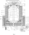
- Fig. 1 is a longitudinal cross sectional view of a tornado type sampling device in accordance with a preferred embodiment of the present invention.
- a tornado type real-time sampling device having an amplified collection function for a gas-borne substance, such as VOCs, or Semi-VOCs, or surface contamination includes: an end cap 101 having an aperture; and a clamping ring 102 disposed on the end cap 101, and, a coarse filter screen 103 and a fine filter screen 104 are mounted over the aperture of the end cap 101 by the clamping ring 102 to prevent large particle substances from entering the sampling device.
- the coarse filter screen not only enables filter out large particles, but also has a stronger rigidity that is able to bear external environment pressure and impact of large particles.
- the fine filter screen is used for filtering out fine solid particles or micro particles.
- an integrated end cap 101 having an aperture also called a sample inlet, may be used.
- a porous element 103 or 104 is arranged over the sample inlet to prevent large particle substances from passing through the end cap 101.
- the sampling device further comprises a rotary gas curtain guide 105 over which the end cap 101 is closed and sealed through an O-type sealing ring 108 such that an upper annular surface is sealed by the end cap 101.
- the rotary gas curtain guide 105 has a cylindrical outer wall and also an inner wall having a cross section, e.g., of a funnel type as shown.
- the gas curtain guide 105 may be a combination of barrel and a funnel type inner wall therein.
- the gas curtain guide 105 may be an integrally formed single piece.
- An angle between the funnel type inner wall and the cylindrical outer wall may be 20° ⁇ 30° , although other values of the angle may be adopted.
- a diameter of the lower end face of the funnel type inner wall of the gas curtain guide 105 is at least two times of a diameter of the upper end face thereof.
- the diameter of a lower opening formed by the funnel type inner wall is at least two times of the diameter of an upper opening formed by the funnel type inner wall.
- This funnel-type design helps to simulate generation of a tornado within the sampling device.
- An interior space is defined by an inner surface of the funnel type inner wall of the gas curtain guide 105, that is, the interior space is defined between two inner wall sections of the gas curtain guide 105 as shown in the sectional view of Fig. 1 .
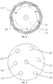
- Fig. 2 shows a schematic cross-sectional view of the side wall of the gas curtain guide 105 along line A-A.
- a plurality of swirl gas holes 106 are formed evenly in the upper end of the funnel type inner wall of the gas curtain guide 105 and have their axial directions closing to be tangent with the funnel type inner wall, and an angle of an axial line of the swirl gas hole 106 relative to a vertical direction is 45° ⁇ 90° .
- the swirl gas holes are tangent with the funnel type inner wall of the gas curtain guide 105 and face downwardly (in an arrow direction shown in Fig. 1 ), such that the gas may flow out from the swirl gas holes and then flow downwardly in a direction that is tangent with the funnel type inner wall.
- a gas inflation inlet 107 is formed in the cylindrical outer wall of the gas curtain guide 105.
- An annular space is defined by the cylindrical outer wall, the funnel type inner wall and the end cap 101 of the rotary gas curtain guide 105. Gas may enter the annular space through the gas inflation inlet 107, and then the gas within the annular space is blown into the funnel type interior space of the gas curtain guide 105 through the swirl gas holes 106 in the funnel type inner wall, generating a swirl gas curtain 130.
- the sample is suctioned at the upper end and is discharged at the lower end, and a flow of inflation gas flows from up to down spirally.
- the sampling device is horizontally placed to face an object to be detected, for example, the sample inlet is placed to face the object to be detected which is located at the left of the sampling device, such that the side of the gas curtain guide 105 where the inlet is provided faces the left object to be detected, the funnel type inner wall is arranged transversely and the sample travels from the left to the right.
- the gas curtain guide 105 may comprises a gas inflation passage 118.
- Fig. 1 shows an arrangement in which one end of the inflation passage 118 is communicated with the gas inflation inlet 107 while the other end is communicated with a gas inflation pump 128 for gas inflation.
- the gas inflation pump 128 delivers the gas into the annular space through the inflation passage 118 and the gas inflation inlet 107, and the gas entered in the annular space is blown into the funnel type interior space through the swirl gas holes 106 of the funnel type inner wall, to form a swirl gas curtain 130.
- the sampling device further comprises a gas guide chamber 109 having a cylindrical inner wall.
- the gas guide chamber 109 is embedded into the sampling device under the gas curtain guide 105 by using an O-ring seal.
- the gas guide chamber 109 may be engaged with the gas curtain guide 105 in any other manner as long as the generation of a tornado type gas flow within the gas guide chamber is not affected.
- the tornado type gas flow is known for those skilled in the art.
- peripheral portions of the gas flow spirally rotate at a high speed or at least quickly, namely, rotate in a horizontal cross-section of the gas flow (it is noted that, in a cross-section of the gas guide chamber in this embodiment) while moving forward (from the end of the sample inlet to the end of the sample feeding opening) in a longitudinal direction, and at the same time, a center portion of the gas flow or a portion of the gas flow at its axis is suctioned forwardly in the longitudinal direction.
- the gas guide chamber 109 is configured for maintaining a tornado type cyclone and guiding the tornado type gas-borne substance, such as VOCs, or Semi-VOCs, or surface contaminations suctioned along the axis to enter a subsequent detection device. As shown in Fig.
- the swirl gas curtain 130 moves downwardly, and enters the gas guide chamber 109 to form a swirl gas flow 131.
- a tornado type swirl gas flow 132 flows in the gas guide chamber 109, passes through a swirl gas outlet 110 at a lower side wall of the gas guide chamber 109, and then is discharged through an exhaust pump interface 123 and a ventilation outlet 127.
- the sampling device further comprises a funnel type bottom cap 113 by which a lower end face of the gas guide chamber 109 is covered with an O-ring seal 108.
- a semipermeable membrane 111 is provided between the bottom cap 113 and the lower end opening of the gas guide chamber 109 and is provided for preventing water molecules, ammonia molecules and other contaminants in the suctioned gas-borne substance, such as VOCs, or Semi-VOCs, or surface contamination from entering and contaminating subsequent chromatographic column or migration tube.
- the semipermeable membrane 111 may further restrict formation of cluster, thereby improving a resolution ratio of the instrument.
- the funnel type bottom cap 113 may form a mixing region or a mixing chamber for the carrier gas and the sample.
- the funnel type bottom cap 113 may comprises a carrier gas passage 121 for introduction of the carrier gas.
- the introduced carrier gas is mixed sufficiently with the sample in the funnel.
- the funnel type bottom cap 113 may further comprises a sample feeding opening 120 through which the collected sample and the carrier gas are discharged after, such as, being mixed and preheated. In some cases, the carrier gas and the sample may be discharged after being mixed directly without preheating.
- the sampling device further comprises a temperature controlling system including a thermal insulation layer 114 provided on the gas guide chamber 109, and a heating rod 116 and a temperature sensor 117 provided within the gas guide chamber 109, and configured to control temperature of the gas guide chamber 109, for example, by heating up.
- the temperature controlling system may control the temperature inside the chamber in a range of 50°C ⁇ 250°C, which helps to quickly gasify high boiling gas-borne substance, such as VOCs, or Semi-VOCs, or surface contamination so that it smoothly passes through the semipermeable membrane, and which also helps to sufficiently mix the gasified sample and the carrier gas entered from the carrier gas passage 121 in the funnel type side wall, effectively improving a detection limit of the instrument on high boiling substrate.
- the collected sample may be brought into the sample feeding opening 120 by the carrier gas.
- the rotary gas curtain guide 105, the gas guide chamber 109 and the bottom cap 113 may be made of metallic materials with good thermal performance.
- the thermal insulation layer 114 may be made of aerogel or glass or ceramic wool which has a thickness of about 10mm.
- Teflon outer casing housing 115 may cover the outside the thermal insulation layer 114.
- the bottom end face of the outer casing housing 115 may be provided with an inflator pump interface 122, an exhaust pump interface 123, a GC column/ion migration tube interface 124, a heating rod leading-out wire 125, a temperature sensor leading-out wire 126, a ventilation outlet 127 and a carrier gas tube interface 136, as shown in Fig. 3 .
- the inflator pump interface 122 and the exhaust pump interface 123 may be connected respectively with a gas pump 128 for continuously supplying a gas pressure so that a tornado type gas flow may be formed inside the sampling device.
- the exhaust pump interface 123 is desired to be arranged in a manner to make the gas resistance as small as possible, so that the opening of the exhaust pump interface in the gas guide chamber is desired to face toward a direction of gas flow, facilitating an easy inflow of the gas flow into the exhaust pump interface.
- the exhaust pump interface 123 may not be connected to the gas exhaust pump 128 and be served directly as a ventilation outlet. In order to discharge the suctioned and amplified tornado type gas flow, several ventilation outlets 127 may be formed.
- the GC column/ion migration tube interface 124 may be connected to a GC column or an ion migration tube.
- the carrier gas tube interface 136 may be connected to a molecular sieve 135 so that the carrier gas will be purified.
- Power of the gas inflation pump or gas exhaust pump 128 as shown may be adjusted as needed. Since the tornado type gas flow has a gas collection and amplification function, a flow rate of the gas exhaust pump is ten times or more of that of the gas inflator pump.
- a gas source for collection of the inflator pump is provided as far as possible from the sampled object 133, for example, by aparting the pump from the sampling end holes by using a retractable and turnable flexible conduit; on the other hand, the gas entering the inflator pump is filtered and purified, avoiding cross contamination of the gas and improving sensitivities of locating and sampling performance of the sampling instrument.
- Front end opening/aperture of the sampling device according to the present invention is placed near an object 133 to be sampled, that is, in a location that is away from the object by 5-10cm, to aim at the object 133, while the gas pump and the gas exhaust pump 128 are turned on.
- the inflation gas flow 129 is inflated through an inflation tube into the annular space of the gas curtain guide 105 via the gas inflation inlet 107.
- a gas pressure is generated within the annular space under the action of a gas pressure continuously applied by the gas inflation pump 28'. With the action of the gas pressure, the gas is blown into interior space of the funnel through the swirl gas holes 106 of the gas curtain guide 105.
- the gas is blown into the interior space in a predefined direction, forming a funnel type swirl gas curtain 130.
- the rotary gas curtain formed continuously moves along the inner wall of the gas guide chamber 109, that is, it rotates quickly around a central axis of the gas guide chamber 109 while moving downwardly, to form a tornado type gas flow 131.
- a central gas pressure of the tornado type gas flow reduces remarkably, e.g., the gas pressure at the central axis is ten times smaller than ambient pressure, accordingly, a great suction force may be generated at the central axis of the gas guide chamber 109.
- the suction force makes the gas-borne substance, such as VOCs, or Semi-VOCs, or surface contamination in the vicinity of the sampled object 133 to be suctioned to be adjacent to the center of the wind axis within the gas guide chamber 109 from a region around the front end aperture of the gas guide chamber 109, and to form a sample gas column that moves downwardly along a central axis of the tornado type gas flow and finally reaches the sample-supplying semipermeable membrane 111.
- This process is similar to a tornado phenomenon of "tornado suction-in water" in the nature.
- the collected sample enters a funnel chamber of the bottom cap 113 through the semipermeable membrane 111, and is quickly gasified under a preheated condition and then is mixed sufficiently with the carrier gas flow 137 entered from the carrier gas passage 121 in the side wall of the bottom cap 113. After that, the carrier gas carrying the sample enters the sample feeding opening 120.
- a cyclone is formed at the periphery of the tornado type gas flow 131 form the gas at the periphery of a rotation center of the tornado type gas flow 31 and moves along the side wall of the gas guide chamber 109.
- gas of the peripheral cyclone enters the outlet 110 and forms a vortex flow 134 that will be discharged through the ventilation outlet 127.
- the outlet 110 is oriented towards a gas flow direction of the cyclone. In the orientation shown in Fig.
- the outlet 110 may be inclined upwardly, and, the outlet may deviate towards a tangential direction of the inner wall, instead of being oriented towards a center of the chamber body, facilitating the opening direction of the outlet to be much closer to the velocity direction of the gas flow at the outlet. That is to say, although the opening direction of the outlet 110 is not strictly opposite to the velocity direction of the gas flow at the outlet, it is close to a direction opposite to the velocity direction of the gas flow at the outlet, such that the gas will enter more easily the outlet 110 and is discharged.
- the sampling device may constantly suction sample molecules, thereby achieving amplified collection of the gas-borne substance, such as VOCs, or Semi-VOCs, or surface contamination.
- the gas-borne substance such as VOCs, or Semi-VOCs, or surface contamination.
- This tornado type real-time sampling device having the gas amplified collection function may be used directly as a sample feeder of analytical instruments including IMS, GC, MS, GC-IMS, GC-MS, etc., and it gives no unnecessary details herein.
- the sampling device comprises a first end and a second end opposite to the first end.
- the sampling device comprises a chamber body, and a part of the chamber body has a funnel shape or a truncated conical shape.
- the chamber body has a sample inlet that is adjacent to the first end and is configured for suction of the sample, and a sample feeding opening 120 that is adjacent to the second end and is configured for discharge of the sample.
- the sample inlet of the chamber body is located adjacent to a smaller-diameter round end of the truncated conical shaped inner wall , and the larger-diameter round end of the truncated conical shaped inner wall is close to the sample outlet.
- the smaller-diameter end of the funnel type inner wall will face the sample, while the larger-diameter end faces towards the sample outlet for discharging the sample.
- the chamber body shown in figure is oriented such that the sample inlet faces upwards while the sample outlet for discharging the sample faces downwards, that is, the funnel type chamber body is arranged in an inverted funnel manner.
- the funnel type chamber body is arranged in an inverted funnel manner.
- the sample inlet is placed to face the object to be detected which is located at the left of the sampling device 100 and a side of the funnel type inner wall where the smaller opening is provided faces the object to be detected at the left, such that the funnel type inner wall is placed in a horizontal arrangement manner.
- the chamber body is further formed with a gas inflation inlet 107 configured to introduce a flow of gas into the chamber body, in order to form a tornado type gas flow within the chamber body.
- the chamber body is further formed with an outlet configured to discharge the gas and to, together with the gas inflation inlet 107 in the chamber body, generate the tornado type gas flow in the chamber body.
- the gas inflation inlet 107 is configured such that an axial gas introduction direction of the gas inflation inlet 107 is approximately tangent to an inner surface of the inner wall of the chamber body but is inclined towards a side of the sample outlet, as shown in Figure 2 .
- the gas curtain guide 105 may not be provided alone, and, an arrangement in which the abovementioned gas inflation inlet 107 and a corresponding gas inflation passage are provided in the inner wall of the chamber body adjacent to the sample inlet will achieve a similar effect as that of the abovementioned gas curtain guide 105.
- an annular space for the gas curtain guide may be formed inside the chamber body, and is configured to accommodate the gas therein to create a gas pressure within the annular space, and, the gas is inflated into the interior space of the sampling device through the gas inflation inlet.
- the outlet 110 is located in wall of the chamber body, and may be arranged in a similar manner to the outlet in the aforementioned embodiment of the present invention.
- the outlet 110 faces toward the tornado type gas flow spirally advanced from the gas inflation inlet 106, so that the gas flow enters the outlet 110 with the gas resistance as small as possible.
- the peripheral gas of the tornado type gas flow formed within the chamber body is discharged through the outlet 110.
- the peripheral gas is not limited to be the gas, and it may contain small amount of the sample.
- An opening direction of the outlet is close to a direction opposite to the velocity direction of the gas flow at the outlet.
- the sampling device may further comprise a filter screen located at a first end side of the sample inlet and configured for preventing large particle substances from entering the sample inlet.
- the filter screen comprises a rigid coarse filter screen for filtration of large particles and a fine filter screen for filtration of fine particles.
- the sampling device may further comprise a temperature-controlling system adapted for controlling a temperature within the chamber body, and the temperature-controlling system comprises a heater for heating up and a temperature sensor for measuring the temperature, provided within a wall of the chamber body.
- the sampling device may further comprise a thermal insulation layer surrounding the wall of the chamber body.
- the chamber body may be an integrated one, or may be an assembled one consisted of several components by means of welding, riveting, etc., which do not bring any substantial effect on the gas flow inside the chamber body.
- the chamber body in this embodiment, may be also provided with an end cap 101, filter screens 103, 104, gas inflation pump 28' and gas exhaust pumps 128, a sample-supplying semipermeable membrane 111, a temperature controlling system, a thermal insulation layer, etc., as those in the aforementioned embodiment.
- the chamber body may further include a mixing region for mixing the carrier gas with the sample. That is, the mixing region is provided at a lower section of the chamber body and is separated, e.g., by the semipermeable membrane 111, from a section of the chamber body where the tornado type gas flow is formed.
- the chamber body may comprise a carrier gas passage 121 at its lower section, which passage is provided for injection of the carrier gas which will be sufficiently mixed with the sample in the funnel.
- the chamber body may further comprise a sample feeding opening 120 at its lower section, through which the collected sample and the carrier gas are discharged after being mixed and preheated.
- the bottom end face of the chamber body may be the same as that in the aforementioned embodiment of the present invention, as shown in Fig. 3 .
- the bottom end face of the chamber body may be provided with an inflator pump interface 122, an exhaust pump interface 123, a GC column/ion migration tube interface 124, a heating rod leading-out wire 125, a temperature sensor leading-out wire 126, a ventilation outlet 127 and a carrier gas tube interface 136.
- the inflator pump interface 122 and the exhaust pump interface 123 may be connected respectively with a gas pump, e.g., a gas inflator pump 28' and gas exhaust pump, for continuously supplying a gas pressure so that a tornado type gas flow is formed inside the sampling device, and, the flow rate of the exhaust pump is ten times or more than the inflator pump.
- the exhaust pump interface 123 is desired to be arranged in a manner to make the gas resistance as small as possible, so the opening of the exhaust pump interface in the gas guide chamber is desired to face toward a flowing direction of the gas flow, facilitating an easy inflow of the gas flow into the exhaust pump interface.
- the exhaust pump interface 123 may not be connected to the gas exhaust pump 128 and be served directly as the ventilation outlet.
- several ventilation outlets 127 may be formed.
- the GC column/ion migration tube interface 124 may be connected directly to an ion migration tube.
- the carrier gas tube interface 136 is connected to a molecular sieve 135 so that the carrier gas will be purified.
- a section of the chamber body has an inner wall with a partially spherical shape, instead of a truncated conical shape. That is to say, the inner wall of this section of the chamber body has such a cambered surface that a portion of the inner wall of the chamber body near the sample inlet has a smaller diameter while a portion of the inner wall of the chamber body near the sample outlet has a larger diameter, so that a tornado type gas flow will be formed inside the chamber body.
- the chamber body in this embodiment, may be also provided with an end cap 1, filter screens 3, 4, inflation and exhaust gas pumps 28, a sample-supplying semipermeable membrane 11, a temperature controlling system, a thermal insulation layer, etc., as those in the aforementioned embodiment.
- the chamber body may further include a mixing region for mixing the carrier gas with the sample. That is, the mixing region is provided at a lower section of the chamber body and is separated, e.g., by the semipermeable membrane 11, from a section of the chamber body where the tornado type gas flow is formed.
- the chamber body may comprise a carrier gas passage 21 at its lower section 13, which passage is provided for injection of the carrier gas which will be sufficiently mixed with the sample in the funnel.
- the chamber body may further comprise a sample feeding opening 20 at its lower section 13, through which the collected sample and the carrier gas are discharged after being mixed and preheated.
- the bottom end face of the chamber body may be the same as that in the aforementioned embodiment of the present invention, as shown in Fig. 3 .
- the bottom end face of the chamber body may be provided with an inflator pump interface 22, an exhaust pump interface 23, a GC column/ion migration tube interface 24, a heating rod leading-out wire 125, a temperature sensor leading-out wire 26, a ventilation outlet 27 and a carrier gas tube interface 36.
- the inflator pump interface 22 and the exhaust pump interface 23 may be connected respectively with a gas pump 28, e.g., a gas inflator pump and gas exhaust pump, for continuously supplying a gas pressure so that a tornado type gas flow is formed inside the sampling device, and, the flow rate of the exhaust pump is ten times or more than the inflator pump.
- the exhaust pump interface 23 is desired to be arranged in a manner to make the gas resistance as small as possible, so the opening of the exhaust pump interface in the gas guide chamber is desired to face toward a flowing direction of the gas flow, facilitating an easy inflow of the gas flow into the exhaust pump interface.
- the exhaust pump interface 23 may not be connected to the gas pump 28 and be served directly as the ventilation outlet.
- the GC column/ion migration tube interface 24 may be connected directly to an ion migration tube.
- the carrier gas tube interface 36 is connected to a molecular sieve 35 so that the carrier gas will be purified.
- a section of the chamber body has an inner wall with a partially spherical shape, instead of a truncated conical shape. That is to say, the inner wall of this section of the chamber body has such a cambered surface that a portion of the inner wall of the chamber body near the sample inlet has a smaller diameter while a portion of the inner wall of the chamber body near the sample outlet has a larger diameter, so that a tornado type gas flow will be formed inside the chamber body.
Applications Claiming Priority (2)
| Application Number | Priority Date | Filing Date | Title |
|---|---|---|---|
| CN201410855315.4A CN104535379B (zh) | 2014-12-31 | 2014-12-31 | 采样装置和气帘引导体 |
| PCT/CN2015/098691 WO2016107487A1 (zh) | 2014-12-31 | 2015-12-24 | 采样装置和气帘引导体 |
Publications (3)
| Publication Number | Publication Date |
|---|---|
| EP3242122A1 EP3242122A1 (en) | 2017-11-08 |
| EP3242122A4 EP3242122A4 (en) | 2018-08-29 |
| EP3242122B1 true EP3242122B1 (en) | 2021-08-11 |
Family
ID=52850953
Family Applications (1)
| Application Number | Title | Priority Date | Filing Date |
|---|---|---|---|
| EP15875165.1A Active EP3242122B1 (en) | 2014-12-31 | 2015-12-24 | Sampling apparatus |
Country Status (6)
| Country | Link |
|---|---|
| US (1) | US10151671B2 (ja) |
| EP (1) | EP3242122B1 (ja) |
| JP (1) | JP6333989B2 (ja) |
| CN (1) | CN104535379B (ja) |
| HK (1) | HK1209828A1 (ja) |
| WO (1) | WO2016107487A1 (ja) |
Families Citing this family (17)
| Publication number | Priority date | Publication date | Assignee | Title |
|---|---|---|---|---|
| WO2014110619A1 (en) * | 2013-01-21 | 2014-07-24 | Metzke Pty Ltd | Drill sample particle distributor |
| CN104535379B (zh) * | 2014-12-31 | 2018-01-16 | 同方威视技术股份有限公司 | 采样装置和气帘引导体 |
| CN105047050B (zh) * | 2015-09-06 | 2017-11-28 | 宁夏大学 | 尘卷模拟装置 |
| CN105628456B (zh) * | 2015-12-18 | 2018-04-13 | 杭州同孚环保科技有限公司 | 一种带气流循环的田间气体采样装置 |
| CN106769268B (zh) * | 2016-12-29 | 2023-11-24 | 清华大学 | 采集进样装置和检查设备 |
| CN106769874B (zh) * | 2016-12-30 | 2023-03-31 | 陕西正大环保科技有限公司 | 一种非接触式水中油传感器用气帘保护结构 |
| CN108195635B (zh) * | 2017-12-25 | 2020-07-03 | 佛山市中环环境检测中心 | 一种废气采样装置 |
| CN107983029A (zh) * | 2017-12-26 | 2018-05-04 | 同方威视技术股份有限公司 | 气体净化装置及痕量物质检测设备 |
| CN108061669A (zh) * | 2017-12-29 | 2018-05-22 | 同方威视技术股份有限公司 | 半挥发性、难挥发性物质采集装置 |
| CN108445111A (zh) * | 2018-05-09 | 2018-08-24 | 清华大学 | 用于样品检测的闸机系统及样品检验方法 |
| CN108956216B (zh) * | 2018-08-29 | 2020-11-17 | 嘉兴嘉卫检测科技有限公司 | 用于环境监测的空气颗粒物分级采样装置 |
| WO2020236158A1 (en) | 2019-05-21 | 2020-11-26 | Cummins Emission Solutions Inc. | Systems and methods for sampling exhaust gas |
| CN111947966B (zh) * | 2020-07-17 | 2023-08-29 | 北京卫星制造厂有限公司 | 一种适用于地外天体的快速破岩采样装置 |
| CN113655139B (zh) * | 2021-07-30 | 2023-07-21 | 内蒙古华测电力科技有限公司 | 一种变压器油气相色谱分析远程控制分析系统 |
| CN113969444A (zh) * | 2021-10-29 | 2022-01-25 | 盐城工学院 | 一种纺织用纺织机纺织尘收集及清扫装置 |
| CN116717640B (zh) * | 2023-05-29 | 2023-12-08 | 上海协微环境科技有限公司 | 一种防水汽反流的法兰组件和尾气处理系统 |
| CN117825223A (zh) * | 2024-03-05 | 2024-04-05 | 中汽研汽车检验中心(天津)有限公司 | 一种基于底盘测功机的制动磨损颗粒物测试系统及方法 |
Family Cites Families (21)
| Publication number | Priority date | Publication date | Assignee | Title |
|---|---|---|---|---|
| JPS5033873B2 (ja) * | 1973-10-24 | 1975-11-04 | ||
| JPS59175157U (ja) * | 1983-05-09 | 1984-11-22 | 三菱重工業株式会社 | ダスト捕集装置 |
| JPS59206741A (ja) * | 1983-05-11 | 1984-11-22 | Mitsubishi Heavy Ind Ltd | 固気混相流体の希釈方法および装置 |
| US5011517A (en) * | 1990-02-12 | 1991-04-30 | Midwest Research Institute | Sampler for chemical vapors |
| JPH0526790A (ja) * | 1991-07-23 | 1993-02-02 | Mitsubishi Electric Corp | ガス置換装置 |
| DE19926285A1 (de) * | 1999-06-09 | 2000-12-14 | Basf Ag | Vorrichtung und Verfahren zur Probenahme für Gase oder Dämpfe |
| US6870155B2 (en) * | 2002-02-15 | 2005-03-22 | Implant Sciences Corporation | Modified vortex for an ion mobility spectrometer |
| US7574930B2 (en) * | 2002-02-15 | 2009-08-18 | Implant Sciences Corporation | Trace chemical sensing |
| US7595487B2 (en) * | 2007-08-24 | 2009-09-29 | Georgia Tech Research Corporation | Confining/focusing vortex flow transmission structure, mass spectrometry systems, and methods of transmitting particles, droplets, and ions |
| CN201184853Y (zh) * | 2008-02-01 | 2009-01-21 | 中国科学院大连化学物理研究所 | 一种用于离子迁移谱仪非接触采样的热吹扫取样装置 |
| CN102539514B (zh) * | 2008-07-16 | 2014-08-06 | 同方威视技术股份有限公司 | 离子迁移谱仪 |
| CN201561956U (zh) * | 2009-06-05 | 2010-08-25 | 中国科学院上海应用物理研究所 | 离子迁移谱仪 |
| CN101936820B (zh) * | 2009-06-30 | 2012-03-07 | 同方威视技术股份有限公司 | 样品收集方法以及样品收集装置 |
| US8919185B2 (en) * | 2009-12-14 | 2014-12-30 | Schlumberger Technology Corporation | System and method for swirl generation |
| JP2011247609A (ja) * | 2010-05-24 | 2011-12-08 | Nissan Motor Co Ltd | 気中粒子検出装置 |
| JP2014085320A (ja) * | 2012-10-26 | 2014-05-12 | Azbil Corp | 粒子濃縮装置及び粒子検出装置 |
| CN104535379B (zh) * | 2014-12-31 | 2018-01-16 | 同方威视技术股份有限公司 | 采样装置和气帘引导体 |
| CN104517799B (zh) * | 2014-12-31 | 2017-09-15 | 同方威视技术股份有限公司 | 检测设备和检测方法 |
| CN204314116U (zh) * | 2014-12-31 | 2015-05-06 | 同方威视技术股份有限公司 | 采样装置和气帘引导体 |
| CN204424206U (zh) * | 2014-12-31 | 2015-06-24 | 同方威视技术股份有限公司 | 检测设备 |
| CN105203692B (zh) * | 2015-10-16 | 2019-03-19 | 同方威视技术股份有限公司 | 安检设备、安检设备的采样装置、安检方法和采样方法 |
-
2014
- 2014-12-31 CN CN201410855315.4A patent/CN104535379B/zh active Active
-
2015
- 2015-10-19 HK HK15110218.8A patent/HK1209828A1/xx not_active IP Right Cessation
- 2015-12-24 JP JP2016548634A patent/JP6333989B2/ja not_active Expired - Fee Related
- 2015-12-24 WO PCT/CN2015/098691 patent/WO2016107487A1/zh active Application Filing
- 2015-12-24 EP EP15875165.1A patent/EP3242122B1/en active Active
-
2016
- 2016-08-16 US US15/238,598 patent/US10151671B2/en active Active
Also Published As
| Publication number | Publication date |
|---|---|
| EP3242122A4 (en) | 2018-08-29 |
| US10151671B2 (en) | 2018-12-11 |
| JP2017508954A (ja) | 2017-03-30 |
| HK1209828A1 (en) | 2016-04-08 |
| WO2016107487A1 (zh) | 2016-07-07 |
| US20160356679A1 (en) | 2016-12-08 |
| CN104535379B (zh) | 2018-01-16 |
| JP6333989B2 (ja) | 2018-05-30 |
| CN104535379A (zh) | 2015-04-22 |
| EP3242122A1 (en) | 2017-11-08 |
Similar Documents
| Publication | Publication Date | Title |
|---|---|---|
| EP3242122B1 (en) | Sampling apparatus | |
| US10429348B2 (en) | Detection apparatus and detection method | |
| CN105203692B (zh) | 安检设备、安检设备的采样装置、安检方法和采样方法 | |
| CN105277577B (zh) | 暗室式安检设备以及方法 | |
| CN105259246B (zh) | 暗室式安检设备以及方法 | |
| CN105655225B (zh) | 一种质谱快速富集‑热解析的膜进样装置及应用 | |
| EP3343197B1 (en) | Gathering and sampling device and inspection apparatus | |
| CN101611304A (zh) | 用于检测设备的气体预浓缩器 | |
| US11117144B2 (en) | Cyclone collector | |
| CN101583867B (zh) | 检测设备 | |
| US10663429B2 (en) | Device for collecting semi-volatile or non-volatile substrate | |
| CN101583868A (zh) | 检测器设备和预浓缩器 | |
| WO2012112040A1 (en) | Detection apparatus | |
| CN204314116U (zh) | 采样装置和气帘引导体 | |
| CN205103226U (zh) | 安检设备和安检设备的采样装置 | |
| RU2625821C2 (ru) | Устройство дистанционного отбора воздушной пробы для приборов газового анализа (варианты) | |
| KR20180061276A (ko) | 샘플링 장치 및 방법 | |
| JP2022132756A (ja) | ケミカルセンサ装置およびケミカルセンサモジュール | |
| CN113945431A (zh) | 一种痕量物质取样装置、分析系统及取样方法 |
Legal Events
| Date | Code | Title | Description |
|---|---|---|---|
| STAA | Information on the status of an ep patent application or granted ep patent |
Free format text: STATUS: THE INTERNATIONAL PUBLICATION HAS BEEN MADE |
|
| PUAI | Public reference made under article 153(3) epc to a published international application that has entered the european phase |
Free format text: ORIGINAL CODE: 0009012 |
|
| STAA | Information on the status of an ep patent application or granted ep patent |
Free format text: STATUS: REQUEST FOR EXAMINATION WAS MADE |
|
| 17P | Request for examination filed |
Effective date: 20160720 |
|
| AK | Designated contracting states |
Kind code of ref document: A1 Designated state(s): AL AT BE BG CH CY CZ DE DK EE ES FI FR GB GR HR HU IE IS IT LI LT LU LV MC MK MT NL NO PL PT RO RS SE SI SK SM TR |
|
| AX | Request for extension of the european patent |
Extension state: BA ME |
|
| DAV | Request for validation of the european patent (deleted) | ||
| DAX | Request for extension of the european patent (deleted) | ||
| A4 | Supplementary search report drawn up and despatched |
Effective date: 20180730 |
|
| RIC1 | Information provided on ipc code assigned before grant |
Ipc: G01N 1/24 20060101AFI20180723BHEP Ipc: G01N 1/00 20060101ALI20180723BHEP |
|
| REG | Reference to a national code |
Ref country code: DE Ref legal event code: R079 Ref document number: 602015072286 Country of ref document: DE Free format text: PREVIOUS MAIN CLASS: G01N0001240000 Ipc: G01N0001220000 |
|
| STAA | Information on the status of an ep patent application or granted ep patent |
Free format text: STATUS: EXAMINATION IS IN PROGRESS |
|
| 17Q | First examination report despatched |
Effective date: 20210324 |
|
| RIC1 | Information provided on ipc code assigned before grant |
Ipc: G01N 1/22 20060101AFI20210325BHEP |
|
| GRAP | Despatch of communication of intention to grant a patent |
Free format text: ORIGINAL CODE: EPIDOSNIGR1 |
|
| STAA | Information on the status of an ep patent application or granted ep patent |
Free format text: STATUS: GRANT OF PATENT IS INTENDED |
|
| INTG | Intention to grant announced |
Effective date: 20210430 |
|
| GRAS | Grant fee paid |
Free format text: ORIGINAL CODE: EPIDOSNIGR3 |
|
| GRAA | (expected) grant |
Free format text: ORIGINAL CODE: 0009210 |
|
| STAA | Information on the status of an ep patent application or granted ep patent |
Free format text: STATUS: THE PATENT HAS BEEN GRANTED |
|
| AK | Designated contracting states |
Kind code of ref document: B1 Designated state(s): AL AT BE BG CH CY CZ DE DK EE ES FI FR GB GR HR HU IE IS IT LI LT LU LV MC MK MT NL NO PL PT RO RS SE SI SK SM TR |
|
| REG | Reference to a national code |
Ref country code: CH Ref legal event code: EP |
|
| REG | Reference to a national code |
Ref country code: DE Ref legal event code: R096 Ref document number: 602015072286 Country of ref document: DE |
|
| REG | Reference to a national code |
Ref country code: IE Ref legal event code: FG4D Ref country code: AT Ref legal event code: REF Ref document number: 1419862 Country of ref document: AT Kind code of ref document: T Effective date: 20210915 |
|
| REG | Reference to a national code |
Ref country code: LT Ref legal event code: MG9D |
|
| REG | Reference to a national code |
Ref country code: NL Ref legal event code: MP Effective date: 20210811 |
|
| REG | Reference to a national code |
Ref country code: AT Ref legal event code: MK05 Ref document number: 1419862 Country of ref document: AT Kind code of ref document: T Effective date: 20210811 |
|
| PG25 | Lapsed in a contracting state [announced via postgrant information from national office to epo] |
Ref country code: FI Free format text: LAPSE BECAUSE OF FAILURE TO SUBMIT A TRANSLATION OF THE DESCRIPTION OR TO PAY THE FEE WITHIN THE PRESCRIBED TIME-LIMIT Effective date: 20210811 Ref country code: ES Free format text: LAPSE BECAUSE OF FAILURE TO SUBMIT A TRANSLATION OF THE DESCRIPTION OR TO PAY THE FEE WITHIN THE PRESCRIBED TIME-LIMIT Effective date: 20210811 Ref country code: PT Free format text: LAPSE BECAUSE OF FAILURE TO SUBMIT A TRANSLATION OF THE DESCRIPTION OR TO PAY THE FEE WITHIN THE PRESCRIBED TIME-LIMIT Effective date: 20211213 Ref country code: NO Free format text: LAPSE BECAUSE OF FAILURE TO SUBMIT A TRANSLATION OF THE DESCRIPTION OR TO PAY THE FEE WITHIN THE PRESCRIBED TIME-LIMIT Effective date: 20211111 Ref country code: AT Free format text: LAPSE BECAUSE OF FAILURE TO SUBMIT A TRANSLATION OF THE DESCRIPTION OR TO PAY THE FEE WITHIN THE PRESCRIBED TIME-LIMIT Effective date: 20210811 Ref country code: BG Free format text: LAPSE BECAUSE OF FAILURE TO SUBMIT A TRANSLATION OF THE DESCRIPTION OR TO PAY THE FEE WITHIN THE PRESCRIBED TIME-LIMIT Effective date: 20211111 Ref country code: LT Free format text: LAPSE BECAUSE OF FAILURE TO SUBMIT A TRANSLATION OF THE DESCRIPTION OR TO PAY THE FEE WITHIN THE PRESCRIBED TIME-LIMIT Effective date: 20210811 Ref country code: SE Free format text: LAPSE BECAUSE OF FAILURE TO SUBMIT A TRANSLATION OF THE DESCRIPTION OR TO PAY THE FEE WITHIN THE PRESCRIBED TIME-LIMIT Effective date: 20210811 Ref country code: RS Free format text: LAPSE BECAUSE OF FAILURE TO SUBMIT A TRANSLATION OF THE DESCRIPTION OR TO PAY THE FEE WITHIN THE PRESCRIBED TIME-LIMIT Effective date: 20210811 Ref country code: HR Free format text: LAPSE BECAUSE OF FAILURE TO SUBMIT A TRANSLATION OF THE DESCRIPTION OR TO PAY THE FEE WITHIN THE PRESCRIBED TIME-LIMIT Effective date: 20210811 |
|
| PG25 | Lapsed in a contracting state [announced via postgrant information from national office to epo] |
Ref country code: PL Free format text: LAPSE BECAUSE OF FAILURE TO SUBMIT A TRANSLATION OF THE DESCRIPTION OR TO PAY THE FEE WITHIN THE PRESCRIBED TIME-LIMIT Effective date: 20210811 Ref country code: LV Free format text: LAPSE BECAUSE OF FAILURE TO SUBMIT A TRANSLATION OF THE DESCRIPTION OR TO PAY THE FEE WITHIN THE PRESCRIBED TIME-LIMIT Effective date: 20210811 Ref country code: GR Free format text: LAPSE BECAUSE OF FAILURE TO SUBMIT A TRANSLATION OF THE DESCRIPTION OR TO PAY THE FEE WITHIN THE PRESCRIBED TIME-LIMIT Effective date: 20211112 |
|
| PG25 | Lapsed in a contracting state [announced via postgrant information from national office to epo] |
Ref country code: NL Free format text: LAPSE BECAUSE OF FAILURE TO SUBMIT A TRANSLATION OF THE DESCRIPTION OR TO PAY THE FEE WITHIN THE PRESCRIBED TIME-LIMIT Effective date: 20210811 |
|
| PG25 | Lapsed in a contracting state [announced via postgrant information from national office to epo] |
Ref country code: DK Free format text: LAPSE BECAUSE OF FAILURE TO SUBMIT A TRANSLATION OF THE DESCRIPTION OR TO PAY THE FEE WITHIN THE PRESCRIBED TIME-LIMIT Effective date: 20210811 |
|
| REG | Reference to a national code |
Ref country code: DE Ref legal event code: R097 Ref document number: 602015072286 Country of ref document: DE |
|
| PG25 | Lapsed in a contracting state [announced via postgrant information from national office to epo] |
Ref country code: SM Free format text: LAPSE BECAUSE OF FAILURE TO SUBMIT A TRANSLATION OF THE DESCRIPTION OR TO PAY THE FEE WITHIN THE PRESCRIBED TIME-LIMIT Effective date: 20210811 Ref country code: SK Free format text: LAPSE BECAUSE OF FAILURE TO SUBMIT A TRANSLATION OF THE DESCRIPTION OR TO PAY THE FEE WITHIN THE PRESCRIBED TIME-LIMIT Effective date: 20210811 Ref country code: RO Free format text: LAPSE BECAUSE OF FAILURE TO SUBMIT A TRANSLATION OF THE DESCRIPTION OR TO PAY THE FEE WITHIN THE PRESCRIBED TIME-LIMIT Effective date: 20210811 Ref country code: EE Free format text: LAPSE BECAUSE OF FAILURE TO SUBMIT A TRANSLATION OF THE DESCRIPTION OR TO PAY THE FEE WITHIN THE PRESCRIBED TIME-LIMIT Effective date: 20210811 Ref country code: CZ Free format text: LAPSE BECAUSE OF FAILURE TO SUBMIT A TRANSLATION OF THE DESCRIPTION OR TO PAY THE FEE WITHIN THE PRESCRIBED TIME-LIMIT Effective date: 20210811 Ref country code: AL Free format text: LAPSE BECAUSE OF FAILURE TO SUBMIT A TRANSLATION OF THE DESCRIPTION OR TO PAY THE FEE WITHIN THE PRESCRIBED TIME-LIMIT Effective date: 20210811 |
|
| PLBE | No opposition filed within time limit |
Free format text: ORIGINAL CODE: 0009261 |
|
| STAA | Information on the status of an ep patent application or granted ep patent |
Free format text: STATUS: NO OPPOSITION FILED WITHIN TIME LIMIT |
|
| REG | Reference to a national code |
Ref country code: DE Ref legal event code: R119 Ref document number: 602015072286 Country of ref document: DE |
|
| 26N | No opposition filed |
Effective date: 20220512 |
|
| PG25 | Lapsed in a contracting state [announced via postgrant information from national office to epo] |
Ref country code: MC Free format text: LAPSE BECAUSE OF FAILURE TO SUBMIT A TRANSLATION OF THE DESCRIPTION OR TO PAY THE FEE WITHIN THE PRESCRIBED TIME-LIMIT Effective date: 20210811 Ref country code: IT Free format text: LAPSE BECAUSE OF FAILURE TO SUBMIT A TRANSLATION OF THE DESCRIPTION OR TO PAY THE FEE WITHIN THE PRESCRIBED TIME-LIMIT Effective date: 20210811 |
|
| REG | Reference to a national code |
Ref country code: CH Ref legal event code: PL |
|
| GBPC | Gb: european patent ceased through non-payment of renewal fee |
Effective date: 20211224 |
|
| PG25 | Lapsed in a contracting state [announced via postgrant information from national office to epo] |
Ref country code: SI Free format text: LAPSE BECAUSE OF FAILURE TO SUBMIT A TRANSLATION OF THE DESCRIPTION OR TO PAY THE FEE WITHIN THE PRESCRIBED TIME-LIMIT Effective date: 20210811 |
|
| REG | Reference to a national code |
Ref country code: BE Ref legal event code: MM Effective date: 20211231 |
|
| PG25 | Lapsed in a contracting state [announced via postgrant information from national office to epo] |
Ref country code: LU Free format text: LAPSE BECAUSE OF NON-PAYMENT OF DUE FEES Effective date: 20211224 Ref country code: IE Free format text: LAPSE BECAUSE OF NON-PAYMENT OF DUE FEES Effective date: 20211224 Ref country code: GB Free format text: LAPSE BECAUSE OF NON-PAYMENT OF DUE FEES Effective date: 20211224 Ref country code: DE Free format text: LAPSE BECAUSE OF NON-PAYMENT OF DUE FEES Effective date: 20220701 |
|
| PG25 | Lapsed in a contracting state [announced via postgrant information from national office to epo] |
Ref country code: FR Free format text: LAPSE BECAUSE OF NON-PAYMENT OF DUE FEES Effective date: 20211231 Ref country code: BE Free format text: LAPSE BECAUSE OF NON-PAYMENT OF DUE FEES Effective date: 20211231 |
|
| PG25 | Lapsed in a contracting state [announced via postgrant information from national office to epo] |
Ref country code: LI Free format text: LAPSE BECAUSE OF NON-PAYMENT OF DUE FEES Effective date: 20211231 Ref country code: CH Free format text: LAPSE BECAUSE OF NON-PAYMENT OF DUE FEES Effective date: 20211231 |
|
| PG25 | Lapsed in a contracting state [announced via postgrant information from national office to epo] |
Ref country code: HU Free format text: LAPSE BECAUSE OF FAILURE TO SUBMIT A TRANSLATION OF THE DESCRIPTION OR TO PAY THE FEE WITHIN THE PRESCRIBED TIME-LIMIT; INVALID AB INITIO Effective date: 20151224 |
|
| PG25 | Lapsed in a contracting state [announced via postgrant information from national office to epo] |
Ref country code: CY Free format text: LAPSE BECAUSE OF FAILURE TO SUBMIT A TRANSLATION OF THE DESCRIPTION OR TO PAY THE FEE WITHIN THE PRESCRIBED TIME-LIMIT Effective date: 20210811 |