EP3242080B1 - Dispositif et procédé de chauffage de fours à l'aide de tubes radiants - Google Patents
Dispositif et procédé de chauffage de fours à l'aide de tubes radiants Download PDFInfo
- Publication number
- EP3242080B1 EP3242080B1 EP16168425.3A EP16168425A EP3242080B1 EP 3242080 B1 EP3242080 B1 EP 3242080B1 EP 16168425 A EP16168425 A EP 16168425A EP 3242080 B1 EP3242080 B1 EP 3242080B1
- Authority
- EP
- European Patent Office
- Prior art keywords
- temperature
- furnace
- burner
- operating mode
- mode
- Prior art date
- Legal status (The legal status is an assumption and is not a legal conclusion. Google has not performed a legal analysis and makes no representation as to the accuracy of the status listed.)
- Active
Links
- 238000010438 heat treatment Methods 0.000 title claims description 39
- 238000000034 method Methods 0.000 title claims description 9
- 230000003647 oxidation Effects 0.000 claims description 25
- 238000007254 oxidation reaction Methods 0.000 claims description 25
- 238000010304 firing Methods 0.000 claims description 11
- 239000000446 fuel Substances 0.000 claims description 8
- 238000002485 combustion reaction Methods 0.000 claims description 6
- 238000001514 detection method Methods 0.000 claims description 4
- 125000004122 cyclic group Chemical group 0.000 claims 1
- MWUXSHHQAYIFBG-UHFFFAOYSA-N nitrogen oxide Inorganic materials O=[N] MWUXSHHQAYIFBG-UHFFFAOYSA-N 0.000 description 15
- 238000004200 deflagration Methods 0.000 description 6
- 230000001419 dependent effect Effects 0.000 description 4
- 239000007789 gas Substances 0.000 description 4
- 238000010586 diagram Methods 0.000 description 3
- 229910000831 Steel Inorganic materials 0.000 description 2
- 238000011161 development Methods 0.000 description 2
- 230000018109 developmental process Effects 0.000 description 2
- VNWKTOKETHGBQD-UHFFFAOYSA-N methane Chemical compound C VNWKTOKETHGBQD-UHFFFAOYSA-N 0.000 description 2
- 239000010959 steel Substances 0.000 description 2
- 238000013459 approach Methods 0.000 description 1
- 230000033228 biological regulation Effects 0.000 description 1
- 230000007423 decrease Effects 0.000 description 1
- 230000000977 initiatory effect Effects 0.000 description 1
- 238000009940 knitting Methods 0.000 description 1
- 239000000463 material Substances 0.000 description 1
- 239000000203 mixture Substances 0.000 description 1
- 238000012986 modification Methods 0.000 description 1
- 230000004048 modification Effects 0.000 description 1
- 239000003345 natural gas Substances 0.000 description 1
- 238000011084 recovery Methods 0.000 description 1
- 230000001105 regulatory effect Effects 0.000 description 1
- 238000011144 upstream manufacturing Methods 0.000 description 1
Images

Classifications
-
- F—MECHANICAL ENGINEERING; LIGHTING; HEATING; WEAPONS; BLASTING
- F23—COMBUSTION APPARATUS; COMBUSTION PROCESSES
- F23C—METHODS OR APPARATUS FOR COMBUSTION USING FLUID FUEL OR SOLID FUEL SUSPENDED IN A CARRIER GAS OR AIR
- F23C3/00—Combustion apparatus characterised by the shape of the combustion chamber
- F23C3/002—Combustion apparatus characterised by the shape of the combustion chamber the chamber having an elongated tubular form, e.g. for a radiant tube
-
- F—MECHANICAL ENGINEERING; LIGHTING; HEATING; WEAPONS; BLASTING
- F23—COMBUSTION APPARATUS; COMBUSTION PROCESSES
- F23N—REGULATING OR CONTROLLING COMBUSTION
- F23N5/00—Systems for controlling combustion
- F23N5/02—Systems for controlling combustion using devices responsive to thermal changes or to thermal expansion of a medium
-
- F—MECHANICAL ENGINEERING; LIGHTING; HEATING; WEAPONS; BLASTING
- F23—COMBUSTION APPARATUS; COMBUSTION PROCESSES
- F23C—METHODS OR APPARATUS FOR COMBUSTION USING FLUID FUEL OR SOLID FUEL SUSPENDED IN A CARRIER GAS OR AIR
- F23C2900/00—Special features of, or arrangements for combustion apparatus using fluid fuels or solid fuels suspended in air; Combustion processes therefor
- F23C2900/99001—Cold flame combustion or flameless oxidation processes
-
- F—MECHANICAL ENGINEERING; LIGHTING; HEATING; WEAPONS; BLASTING
- F23—COMBUSTION APPARATUS; COMBUSTION PROCESSES
- F23K—FEEDING FUEL TO COMBUSTION APPARATUS
- F23K2900/00—Special features of, or arrangements for fuel supplies
- F23K2900/05003—Non-continuous fluid fuel supply
-
- F—MECHANICAL ENGINEERING; LIGHTING; HEATING; WEAPONS; BLASTING
- F23—COMBUSTION APPARATUS; COMBUSTION PROCESSES
- F23N—REGULATING OR CONTROLLING COMBUSTION
- F23N2237/00—Controlling
- F23N2237/10—High or low fire
-
- Y—GENERAL TAGGING OF NEW TECHNOLOGICAL DEVELOPMENTS; GENERAL TAGGING OF CROSS-SECTIONAL TECHNOLOGIES SPANNING OVER SEVERAL SECTIONS OF THE IPC; TECHNICAL SUBJECTS COVERED BY FORMER USPC CROSS-REFERENCE ART COLLECTIONS [XRACs] AND DIGESTS
- Y02—TECHNOLOGIES OR APPLICATIONS FOR MITIGATION OR ADAPTATION AGAINST CLIMATE CHANGE
- Y02E—REDUCTION OF GREENHOUSE GAS [GHG] EMISSIONS, RELATED TO ENERGY GENERATION, TRANSMISSION OR DISTRIBUTION
- Y02E20/00—Combustion technologies with mitigation potential
- Y02E20/34—Indirect CO2mitigation, i.e. by acting on non CO2directly related matters of the process, e.g. pre-heating or heat recovery
Definitions
- the invention relates to a furnace heating device and a method for igniting burners set up for flameless oxidation for heating clocked jet pipes.
- control device by means of which the burner of the steel tube on and off and can be switched between the two modes.
- the temperature of the furnace chamber is regulated by means of the control device. If it is below a critical temperature which must at least be present in a combustion chamber for flameless oxidation of the fuel used, the burner is operated with a flame.
- Jet pipes are typically used for indirect heating of industrial furnaces for temperatures up to about 1200 ° C.
- the radiant tubes are heated from the inside, wherein the heating of the radiant tube can be done by flameless oxidation, which greatly reduces the nitrogen oxides in the exhaust gas.
- the furnace temperature is in operation, depending on the application, for example, below 850 ° C.
- Such furnace temperatures which are typically below 900 ° C but significantly above 700 ° C, can be generated by jet pipes. If the radiant tubes are heated by burners with flame and, for reasons of saving energy, high air preheating is used (in particular air preheating of more than 500 ° C.), the resulting nitrogen oxide values are unacceptably high.
- furnace operating temperature of at least 850 ° C. is required for radiant tube-heated furnaces in order to be able to commission a burner reliably with flameless oxidation. If the oven temperature is lower in clocked mode, i. Turn on and off burners for power regulation, but deflagration occur. In that regard, furnace operating temperatures below 850 ° C (but above 700 ° C) for pulsed flameless burner operation (flameless pulse firing) are considered critical.
- the furnace heating device comprises at least one, preferably a plurality of jet pipes, each by means of (at least) a burner can be heated in a first mode with flame and in a second mode without flame, ie operable with flameless oxidation.
- the interior of the jet pipe is preferably sealed against the furnace chamber.
- At least one control device is provided, by means of which the burner (s) of the jet pipes can be switched on and off and can be switched over between the first and the second operating mode.
- the temperature of the interior of the jet pipe is with active burner above the temperature of the furnace chamber. In operating pauses, which occur repeatedly with pulse firing, the temperature in the interior of the jet pipes approaches from above the furnace temperature.
- the control means is adapted to operate the burner at warm start, i. with the oven at operating temperature, briefly in the first mode and then in the second mode. If the burner of the jet is clocked, i. operated with so-called pulse firing, the burner must be started again and again reliable. This is preferably carried out in each case with the ignition of a flame, which burns for a few seconds.
- the temperature of the interior of the jet pipe can be maintained despite a relatively low (critical) furnace operating temperature of e.g. only 800 ° C to a temperature above 850 ° C, e.g. 900 ° C, after which it is safely switched to the flameless operating mode.
- the oven heating means may comprise means for at least locally detecting the oven temperature, e.g. in the form of one or more switching temperature sensor. If such a temperature sensor is located at a location of an industrial furnace, it determines the switching on and off of burners on the basis of the furnace temperature, but not based on the burner temperature. In burners operated in groups, it may therefore happen that individual burners have a temperature that readily allows the initiation of flameless oxidation at the burner start, while others are not suitable. However, due to the fact that the burners are ignited for a short time in the first operating mode and the subsequent switching to the second operating mode, all the burners are reliably ignited and deflagrations are avoided. The short-term operation in the first operating mode at warm start is a safety operation phase for deflagration avoidance.
- the time period for the operation of the burners in the first mode is preferably a few seconds, e.g. 5 s or 3 s.
- the resulting nitrogen oxides are negligible because of the short time span.
- the burner for heating the jet pipe in a hot furnace after a fire break when the operating temperature of the furnace is below a temperature limit for flameless oxidation, ignited in a first mode with flame (safety mode) and regardless the furnace temperature, which is still below the temperature limit, is switched to the second flameless oxidation mode shortly thereafter.
- the temperature in the furnace chamber has fallen below the lower temperature T u during a break in the operation of the burner, it is ignited in cold start mode and the flame is maintained at the burner until the temperature in the furnace chamber reaches the lower temperature again.
- FIG. 1 there is illustrated an oven heating device 10 which includes at least one, preferably a plurality, of radiant heating tubes 11-14, which are referred to herein as "jet tubes” throughout. These protrude from a furnace wall 15 in a furnace chamber 16 to heat therein not further illustrated Good mainly by radiant heat.
- the jet pipes 11 to 14 are characterized by in FIG. 1 only symbolically shown burner 17, 18, 19, 20 heated, preferably operate gas-powered and heat the jet pipes 11 to 14 from the inside.
- the burners 17 to 20 serve to heat the interiors of the jet pipes 11 to 14 and are arranged at an open end of each jet pipe 11 to 14, the other end is preferably closed.
- a burner is arranged at both ends of a jet pipe.
- the jet pipes 11 to 14 may be stretched and straight as shown, or may also have one or more loops. Its interior is separated from the furnace chamber 16 by the jet tube wall.
- Each burner 17 to 20 has heat recovery devices, for example in the form of recuperators and / or regenerators, to use exhaust heat to preheat combustion air (and fuel).
- the burners 17 to 20 preferably operate with high air preheating, so that the air supplied to the combustion has a temperature of above 500 ° C.
- the air, gas and exhaust pipes and control elements arranged therein, eg valves, are in FIG. 1 not shown separately.
- the burners 17 to 20 can be operated in a first mode F in which they form a flame.
- This operating mode is used for cold start, ie for heating operation of the jet pipes 11 to 14 and the furnace chamber.
- the previously operated in the first mode F burners 17 to 20 in a second mode NF without flame (operation with flameless oxidation FLOX®) can be switched.
- the second operating mode NF is characterized by a particularly low generation of NOx.
- the lowest temperature T u of the furnace space at which FLOX® operation, ie operation in the second operating mode NF is possible, may be, for example, 750 ° C. ( FIG. 3 ).
- a control device 21 For switching on and off of the burners 17 to 20 and for switching the burners 17 to 20 from the first operating mode F to the second operating mode NF (or vice versa), a control device 21 is provided.
- the control device controls, as indicated by knitting arrows 22, 23, 24, 25, the operation of the group formed by the burner 17 to 20 group, for example, together (ie simultaneously) on and off to the temperature of the oven chamber 16, for in the way of a two-point control to the target temperature T s of eg 770 ° C to keep.
- the temperature T s is slightly above the temperature T u .
- a temperature detection device 26 For detecting the furnace temperature T, a temperature detection device 26 is provided, which has at least one, possibly also a plurality of temperature sensors 27, 28.
- the temperature sensors 27, 28 are preferably designed as a temperature switch.
- the temperature sensor 27 may be set to the desired oven temperature T s and to have a switching temperature of eg 770 ° C.
- the temperature sensor 27 may serve to cause the pulse firing of the burners 17 to 20 to regulate the furnace temperature to the desired value.
- the second temperature sensor 28 may be set to the lowest temperature T u , at which an active burner of the first mode F in the second mode NF is switchable. For example, it may have a switching temperature of 750 ° C.
- the furnace heating device 10 described so far operates as follows:
- the controller 21 starts all burners 17 to 20 with flame, ie in the first mode F, and heats the jet pipes 11 to 14 and thus the furnace chamber 16. This process can take a considerable amount of time, which is typically longer than several minutes.
- the controller 21 switches the burners 17 to 20 in this mode NF. In this operating mode NF, the heating is continued until the setpoint temperature T s is reached or exceeded.
- the jet pipes 11 to 14 have from the furnace temperature T u on the burner, ie in their interiors, a temperature at which flameless operation is possible, for example, a temperature above the critical temperature T k of, for example, 850 ° C.
- this temperature T s is maintained by pulsed-fire operation of the burners 17 to 20.
- the temperature sensor 27 switches on and off with a certain hysteresis when the operating temperature is exceeded and undershot, ie it gives a switching signal to the control device 21.
- the control device 21 switches on the burners 17 to 20 as soon as the setpoint temperature T s is exceeded.
- the burners 17 to 20, however, are switched off when the setpoint temperature T s is exceeded.
- the real temperature T of the furnace chamber 16 shifts according to the switching hysteresis by the temperature T s .
- the furnace temperature in pulse firing operation is at or above the lowest temperature T u (eg 750 ° C)
- flameless operation FL is possible, and flaming operation (second operation mode NF) is switched over during firing of flame operation (first mode F) when the burners are switched on, the burners 17 to 20 are each operated for a short time ⁇ t in the first operating mode F with a flame.
- the burners 17 to 20 can be ignited deflagration, even if the jet pipes 11 to 14 have less than the critical temperature T k (typically 850 ° C).
- the controller 21 switches the burners 17 to 20 in flameless operation NF.
- the burners 17 to 20 are then inactive for a certain time, whereby the jet pipes 11 to 14 cool down again to oven temperature (eg 770 ° C). If the oven temperature T s is exceeded, The temperature sensor 27 responds again and causes the controller 21 to reconnect the burners 17 to 20. This is again done with an upstream mode F for a period of time .DELTA.t, after which the mode NF is transferred.
- oven temperature eg 770 ° C
- the temperature sensor 27 responds again and causes the controller 21 to reconnect the burners 17 to 20. This is again done with an upstream mode F for a period of time .DELTA.t, after which the mode NF is transferred.
- the kiln heating device 10 described so far has at least two operating modes, namely heating of the jet pipes 11 to 14 with the burners 17 to 20 in the first operating mode F and control operation, by means of pulse firing, in which the burners 17 to 20 to maintain a desired furnace temperature T s pulsed is switched on and off.
- the furnace temperature T s is in normal operation below a suitable flameless oxidation critical temperature T k .
- This temperature T k is dependent on the fuel used, for natural gas it is about 850 ° C.
- control mode pulse fire mode
- the burners 17 to 20 are therefore always ignited in a start sequence in which the burners 17 to 20 are ignited at start for a short period .DELTA.t in the first mode F, wherein after the expiration of the period .DELTA.t in the second mode NF with flameless oxidation is transferred.
- the furnace chamber 16 can be operated at moderate operating temperatures T s of below T k with high air preheating and thus best energy utilization at the same time low nitrogen oxide emissions.
- the burner is thus ignited when restarting at a furnace temperature T, which is above the temperature T u , has passed at the after the cold start from the first mode F in the second mode NF, the burner is now when restarting in the first mode F ignited and only a few seconds later switched to the second mode NF.
- a temperature sensor for temperatures in the oven space 16 above 850 ° C can send a signal to the controller 21 so that it starts the burners without a first mode F immediately in the second mode NF.
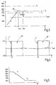
- the time period .DELTA.t for which the burners 17 to 20 at each start according to FIG. 4 in the first operating mode F with flame, depends on the furnace chamber temperature.
- the period .DELTA.t between a first temperature limit T 1 , above which the burners 17 to 20 can be ignited deflagration directly in the second mode NF, and a second temperature limit T 2 , below which operation of the burner 17 to 20 in flameless operation , ie in the second mode NF is not possible to be variably sized.
- the time period ⁇ t is equal to zero.
- the period ⁇ t is large or not fixed.
- a functional profile for the period .DELTA.t can be specified be, in the context of which the period .DELTA.t decreases to higher temperatures.
- the functional course can run continuously or as shown in dashed lines in one or more stages. A linear course is possible.
- the jet pipe For indirect heating of a furnace chamber 16 with jet pipes 11 to 14, heating energy is transmitted through the jet pipe wall into the furnace chamber 16. In stationary operation, an excess temperature is created in the jet pipe 11 to 14 and at its surface in comparison to the furnace, which depends on the specific heat output of the jet pipe 11 to 14.
- the jet pipe At a furnace temperature of eg 770 ° C ( ⁇ T k ) and a heating power of 50 kW / m 2 , the jet pipe has an internal temperature of 900 ° C (> T k ).
- the fuel-dependent critical temperature T k from which flameless oxidation is possible, can be, for example, 850 ° C.
- the jet pipe 11 to 14 can operate with this power in continuous operation with flameless oxidation, although in the furnace only 770 ° C ( ⁇ T k ) are present. However, if the jet pipe 11 to 14 has cooled to a temperature below T k in a fire break, deflagration on ignition of the associated burner is avoided by initially operating it with flame (operating mode F) for a few seconds before switching to operating mode NF.
Landscapes
- Engineering & Computer Science (AREA)
- Chemical & Material Sciences (AREA)
- Combustion & Propulsion (AREA)
- Mechanical Engineering (AREA)
- General Engineering & Computer Science (AREA)
- Combustion Of Fluid Fuel (AREA)
- Control Of Combustion (AREA)
- Waste-Gas Treatment And Other Accessory Devices For Furnaces (AREA)
Claims (11)
- Dispositif de chauffage de fours, en particulier de fours industriels destinés au traitement thermique de produits dans une enceinte de four (16)
comprenant au moins un tube radiant (11) destiné au chauffage de l'enceinte de four (16) et pouvant être chauffé à l'aide d'un brûleur (17) qui peut travailler dans un premier mode de fonctionnement (F) à flammes et dans un deuxième mode de fonctionnement (NF) à oxydation sans flamme,
comprenant au moins un dispositif de commande (21) qui permet de mettre en marche et d'arrêter le brûleur (17) du tube radiant (11) et de le commuter entre les modes de fonctionnement (F, NF),
la température (T) de l'enceinte de four (16) étant fixée à l'aide du dispositif de commande (21) à une température de consigne (Ts) qui est inférieure à une température critique (Tk) devant régner au minimum dans une chambre de combustion à oxydation sans flammes du combustible utilisé, mais qui est supérieure à une température inférieure (Tu) à laquelle le brûleur (17) du tube radiant (11) peut fonctionner sans flammes,
le dispositif de commande (21) étant conçu pour faire fonctionner le brûleur (17) dans le deuxième mode de fonctionnement (NF) lorsque la température (T) de l'enceinte de four (16) est inférieure à la température critique (Tk), caractérisé en ce que le dispositif de commande (21) est conçu pour activer le brûleur (17) d'abord dans le premier mode de fonctionnement (F) lorsque, au démarrage, la température (T) de l'enceinte de four (16) est inférieure à la température critique (Tk) mais supérieure à la température inférieure (Tu), et pour le faire fonctionner dans ce mode pendant un laps de temps (Δt), puis pour le faire passer au deuxième mode de fonctionnement (NF). - Dispositif de chauffage de fours selon la revendication 1, caractérisé en ce qu'il est prévu un dispositif (26) qui est destiné à la mesure, au moins locale, de la température du four et qui est relié au dispositif de commande (21).
- Dispositif de chauffage de fours selon la revendication 2, caractérisé en ce que le dispositif (26) de mesure, au moins locale, de la température du four présente au moins un capteur de température (27) à déclenchement.
- Dispositif de chauffage de fours selon la revendication 2 ou 3, caractérisé en ce que le dispositif (26) de mesure, au moins locale, de la température du four est placé à distance du tube radiant (11), à l'extérieur de celui-ci.
- Dispositif de chauffage de fours selon l'une des revendications 1 à 4, caractérisé en ce que le dispositif de commande (21) est conçu pour mettre en marche et arrêter le brûleur (17), au nombre d'au moins un, en vue de la régulation de la température de l'enceinte de four (16).
- Dispositif de chauffage de fours selon la revendication 1, caractérisé en ce que le laps de temps (Δt) est défini et est de préférence de quelques secondes .
- Dispositif de chauffage de fours selon la revendication 1, caractérisé en ce que le laps de temps (Δt) est défini en fonction de la température (T) de l'enceinte de four (16).
- Procédé d'allumage et de fonctionnement de brûleurs (17) destinés au chauffage de tubes radiants (11) à fonctionnement intermittent, lorsque le four est chaud, en mode de démarrage à chaud après une interruption de chauffe, selon lequel- la température de fonctionnement (T) du four est inférieure à une température critique (Tk) qui doit au minimum régner dans une chambre de combustion à oxydation sans flammes du combustible utilisé, mais qui est supérieure à une température inférieure (Tu) à laquelle le brûleur (17) du tube radiant (11) peut fonctionner sans flammes, sachant que- le brûleur (17) est démarré dans un premier mode de fonctionnement (F) dans lequel il travaille avec des flammes et fonctionne pendant un laps de temps (Δt), et sachant que- indépendamment du fait que la température du four (T) continue d'être inférieure au seuil de température (Tk), le brûleur (17) est commuté à un deuxième mode de fonctionnement (NF) à oxydation sans flammes.
- Procédé selon la revendication 8, caractérisé en ce que, en mode de démarrage à froid, à une température de l'enceinte de four (16) qui est inférieure à la température inférieure (Tu), les brûleurs (17) sont démarrés dans le premier mode de fonctionnement (F) à flammes et continuent à fonctionner dans ce mode, et en ce que les brûleurs (17) sont commutés au deuxième mode de fonctionnement (NF) sans flammes, dès que la température (T) de l'enceinte de four (16) dépasse la température inférieure (Tu).
- Procédé selon la revendication 8 ou 9, caractérisé en ce que pour régler la température (T) de l'enceinte de four à la température (Ts) souhaitée, les brûleurs (17) fonctionnent en mode de chauffe pulsé.
- Procédé selon la revendication 10, caractérisé en ce que la température (Ts) souhaitée de l'enceinte de four (16) est supérieure à la température inférieure (Tu) mais inférieure à la température critique (Tk).
Priority Applications (5)
| Application Number | Priority Date | Filing Date | Title |
|---|---|---|---|
| EP16168425.3A EP3242080B1 (fr) | 2016-05-04 | 2016-05-04 | Dispositif et procédé de chauffage de fours à l'aide de tubes radiants |
| JP2018555454A JP7038665B2 (ja) | 2016-05-04 | 2017-04-28 | 放射管を用いた炉加熱装置および炉加熱方法 |
| PCT/EP2017/060155 WO2017191040A1 (fr) | 2016-05-04 | 2017-04-28 | Dispositif et procédé de chauffage de fours au moyen de tubes radiants |
| KR1020187031557A KR102366351B1 (ko) | 2016-05-04 | 2017-04-28 | 방사 튜브에 의해서 노를 가열하기 위한 장치 및 방법 |
| US16/098,766 US10830432B2 (en) | 2016-05-04 | 2017-04-28 | Device and method for heating furnaces by means of radiant tubes |
Applications Claiming Priority (1)
| Application Number | Priority Date | Filing Date | Title |
|---|---|---|---|
| EP16168425.3A EP3242080B1 (fr) | 2016-05-04 | 2016-05-04 | Dispositif et procédé de chauffage de fours à l'aide de tubes radiants |
Publications (2)
| Publication Number | Publication Date |
|---|---|
| EP3242080A1 EP3242080A1 (fr) | 2017-11-08 |
| EP3242080B1 true EP3242080B1 (fr) | 2019-07-10 |
Family
ID=55913532
Family Applications (1)
| Application Number | Title | Priority Date | Filing Date |
|---|---|---|---|
| EP16168425.3A Active EP3242080B1 (fr) | 2016-05-04 | 2016-05-04 | Dispositif et procédé de chauffage de fours à l'aide de tubes radiants |
Country Status (5)
| Country | Link |
|---|---|
| US (1) | US10830432B2 (fr) |
| EP (1) | EP3242080B1 (fr) |
| JP (1) | JP7038665B2 (fr) |
| KR (1) | KR102366351B1 (fr) |
| WO (1) | WO2017191040A1 (fr) |
Families Citing this family (1)
| Publication number | Priority date | Publication date | Assignee | Title |
|---|---|---|---|---|
| US20230143249A1 (en) | 2021-11-08 | 2023-05-11 | Honeywell International Inc. | Safe start-up of a cooled radiant tube burner at high temperature operation |
Citations (19)
| Publication number | Priority date | Publication date | Assignee | Title |
|---|---|---|---|---|
| EP0463218A1 (fr) | 1990-06-29 | 1992-01-02 | Joachim Dr.-Ing. Wünning | Procédé et dispositif de combustion du combustible dans une chambre de combustion |
| EP0685683A2 (fr) | 1994-06-02 | 1995-12-06 | Joachim Dr.-Ing. Wünning | Brûleur industriel à faible émission de NOx |
| US20030037736A1 (en) | 2000-01-14 | 2003-02-27 | Wunning Joachim G | Tubular oven |
| DE10217524A1 (de) | 2002-04-19 | 2003-11-06 | Ws Waermeprozesstechnik Gmbh | Brenner mit seitlichem Austritt zur flammenlosen Oxidation |
| US20060199127A1 (en) | 2005-03-01 | 2006-09-07 | Fina Technology, Inc. | Heating hydrocarbon process flow using flameless oxidation burners |
| US20060222578A1 (en) | 2005-03-10 | 2006-10-05 | Peter Veenstra | Method of starting up a direct heating system for the flameless combustion of fuel and direct heating of a process fluid |
| US20070037107A1 (en) | 2005-08-11 | 2007-02-15 | Lbe Feuerungstechnik Gmbh | Industrial burner and method for operating an industrial burner |
| US20070072141A1 (en) | 2003-11-28 | 2007-03-29 | Marco Daneri | Low polluting emission gas burner |
| US20080253430A1 (en) | 2007-04-13 | 2008-10-16 | Aga Ab | Method for measuring the temperature in a furnace |
| US20090136406A1 (en) | 2007-11-27 | 2009-05-28 | John Zink Company, L.L.C | Flameless thermal oxidation method |
| US20090148799A1 (en) | 2007-12-10 | 2009-06-11 | Aga Ab | Method for burner and burner device |
| EP1893915B1 (fr) | 2005-06-14 | 2011-08-03 | Elster GmbH | Systeme bruleur et son mode de fonctionnement |
| US20120315584A1 (en) | 2009-12-01 | 2012-12-13 | Davide Astesiano | Industrial burner and related combustion process for heat treatment furnaces |
| US20130157204A1 (en) | 2011-12-20 | 2013-06-20 | Eclipse, Inc. | METHOD AND APPARATUS FOR A DUAL MODE BURNER YIELDING LOW NOx EMISSION |
| US20130260323A1 (en) | 2012-04-03 | 2013-10-03 | Eclipse, Inc. | METHOD AND APPARATUS FOR A DUAL MODE BURNER YIELDING LOW NOx EMISSION |
| EP1995515B1 (fr) | 2007-05-23 | 2013-10-30 | WS-Wärmeprozesstechnik GmbH | Fonctionnement FLOX pris en charge et son brûleur |
| US20140080072A1 (en) | 2012-09-14 | 2014-03-20 | Eclipse, Inc. | Method and apparatus for a dual mode burner yielding low nox emission |
| EP2778521B1 (fr) | 2013-03-13 | 2018-07-04 | Fives North American Combustion, Inc. | Procédé et appareil de combustion diffuse |
| US10288285B2 (en) | 2013-11-20 | 2019-05-14 | Tenova S.P.A. | Self-regenerating industrial burner and industrial furnace for carrying out self-regenerating combustion processes |
Family Cites Families (2)
| Publication number | Priority date | Publication date | Assignee | Title |
|---|---|---|---|---|
| JP2004271130A (ja) | 2003-03-11 | 2004-09-30 | Toho Gas Co Ltd | リジェネバーナの燃焼方法 |
| US20090133854A1 (en) | 2007-11-27 | 2009-05-28 | Bruce Carlyle Johnson | Flameless thermal oxidation apparatus and methods |
-
2016
- 2016-05-04 EP EP16168425.3A patent/EP3242080B1/fr active Active
-
2017
- 2017-04-28 KR KR1020187031557A patent/KR102366351B1/ko active IP Right Grant
- 2017-04-28 JP JP2018555454A patent/JP7038665B2/ja active Active
- 2017-04-28 US US16/098,766 patent/US10830432B2/en active Active
- 2017-04-28 WO PCT/EP2017/060155 patent/WO2017191040A1/fr active Application Filing
Patent Citations (19)
| Publication number | Priority date | Publication date | Assignee | Title |
|---|---|---|---|---|
| EP0463218A1 (fr) | 1990-06-29 | 1992-01-02 | Joachim Dr.-Ing. Wünning | Procédé et dispositif de combustion du combustible dans une chambre de combustion |
| EP0685683A2 (fr) | 1994-06-02 | 1995-12-06 | Joachim Dr.-Ing. Wünning | Brûleur industriel à faible émission de NOx |
| US20030037736A1 (en) | 2000-01-14 | 2003-02-27 | Wunning Joachim G | Tubular oven |
| DE10217524A1 (de) | 2002-04-19 | 2003-11-06 | Ws Waermeprozesstechnik Gmbh | Brenner mit seitlichem Austritt zur flammenlosen Oxidation |
| US20070072141A1 (en) | 2003-11-28 | 2007-03-29 | Marco Daneri | Low polluting emission gas burner |
| US20060199127A1 (en) | 2005-03-01 | 2006-09-07 | Fina Technology, Inc. | Heating hydrocarbon process flow using flameless oxidation burners |
| US20060222578A1 (en) | 2005-03-10 | 2006-10-05 | Peter Veenstra | Method of starting up a direct heating system for the flameless combustion of fuel and direct heating of a process fluid |
| EP1893915B1 (fr) | 2005-06-14 | 2011-08-03 | Elster GmbH | Systeme bruleur et son mode de fonctionnement |
| US20070037107A1 (en) | 2005-08-11 | 2007-02-15 | Lbe Feuerungstechnik Gmbh | Industrial burner and method for operating an industrial burner |
| US20080253430A1 (en) | 2007-04-13 | 2008-10-16 | Aga Ab | Method for measuring the temperature in a furnace |
| EP1995515B1 (fr) | 2007-05-23 | 2013-10-30 | WS-Wärmeprozesstechnik GmbH | Fonctionnement FLOX pris en charge et son brûleur |
| US20090136406A1 (en) | 2007-11-27 | 2009-05-28 | John Zink Company, L.L.C | Flameless thermal oxidation method |
| US20090148799A1 (en) | 2007-12-10 | 2009-06-11 | Aga Ab | Method for burner and burner device |
| US20120315584A1 (en) | 2009-12-01 | 2012-12-13 | Davide Astesiano | Industrial burner and related combustion process for heat treatment furnaces |
| US20130157204A1 (en) | 2011-12-20 | 2013-06-20 | Eclipse, Inc. | METHOD AND APPARATUS FOR A DUAL MODE BURNER YIELDING LOW NOx EMISSION |
| US20130260323A1 (en) | 2012-04-03 | 2013-10-03 | Eclipse, Inc. | METHOD AND APPARATUS FOR A DUAL MODE BURNER YIELDING LOW NOx EMISSION |
| US20140080072A1 (en) | 2012-09-14 | 2014-03-20 | Eclipse, Inc. | Method and apparatus for a dual mode burner yielding low nox emission |
| EP2778521B1 (fr) | 2013-03-13 | 2018-07-04 | Fives North American Combustion, Inc. | Procédé et appareil de combustion diffuse |
| US10288285B2 (en) | 2013-11-20 | 2019-05-14 | Tenova S.P.A. | Self-regenerating industrial burner and industrial furnace for carrying out self-regenerating combustion processes |
Non-Patent Citations (1)
| Title |
|---|
| "Handbuch der Brennertechnik für Industrieöfen", 1 January 2007, article JOACHIM G WÜNNING: "Handbuch der Brennertechnik für Industrieöfen", pages: 1 - 13, XP055743662 |
Also Published As
| Publication number | Publication date |
|---|---|
| JP7038665B2 (ja) | 2022-03-18 |
| US10830432B2 (en) | 2020-11-10 |
| JP2019515229A (ja) | 2019-06-06 |
| EP3242080A1 (fr) | 2017-11-08 |
| US20190120483A1 (en) | 2019-04-25 |
| KR20190004706A (ko) | 2019-01-14 |
| WO2017191040A1 (fr) | 2017-11-09 |
| KR102366351B1 (ko) | 2022-02-23 |
Similar Documents
| Publication | Publication Date | Title |
|---|---|---|
| EP1995515B1 (fr) | Fonctionnement FLOX pris en charge et son brûleur | |
| DE69714882T2 (de) | Brenner und Verbrennungsverfahren in einem Ofen | |
| EP2358986B1 (fr) | Moteur à combustion interne et procédé pour la combustion à allumage par compression | |
| EP2508829A1 (fr) | Procédé et four industriel pour l'exploitation d'un gaz protecteur utilisé comme gaz de chauffage | |
| EP3242080B1 (fr) | Dispositif et procédé de chauffage de fours à l'aide de tubes radiants | |
| EP1893915B1 (fr) | Systeme bruleur et son mode de fonctionnement | |
| DE3134798A1 (de) | Brennanlage, insbesondere zur herstellung von zementklinker | |
| DE2701585C2 (de) | Verfahren und Vorrichtung zum Beheizen eines Ofenraumes | |
| EP3475611B1 (fr) | Brûleur à tube radiant ouvert | |
| WO2020253970A1 (fr) | Brûleur pour réduire les émissions de nox et procédé permettant de faire fonctionner le brûleur | |
| EP2318762B1 (fr) | Dispositif pour le préchauffage continu d'un mélange constitué de gaz combustible, en particulier de gaz naturel, et d'oxygène | |
| DE2641674C2 (de) | Tunnelofen zum Brennen von Leichtziegeln unter Beimischung von geringwertigen Brennstoffen mit hohem Anteil an flüchtigen Bestandteilen | |
| DE60112657T9 (de) | Gasbeheizte Anlage zur Aufkohlung bzw. Einsatzhärtung | |
| EP3650753B1 (fr) | Procédé et dispositif de combustion étagée sans inflammation | |
| EP2947291B1 (fr) | Procédé de démarrage d'un réacteur thermique | |
| EP2527734A1 (fr) | Brûleur industriel doté d'une émission de NOX réduite | |
| WO2021083633A1 (fr) | Procédé de fonctionnement d'un système de purification de gaz d'échappement agencé dans la ligne d'échappement d'un moteur à combustion interne, et système de purification de gaz d'échappement | |
| EP3456850A1 (fr) | Procédé et apparéil de commande de combustion et four | |
| EP1971805B1 (fr) | Bruleur de chauffage | |
| DE3534447C2 (fr) | ||
| DE102006014633B4 (de) | Heizbrenner | |
| AT11715U1 (de) | Backofensystem mit einem biomassebrenner | |
| EP3322953A1 (fr) | Dispositif et procédé pour réchauffer des produits métalliques | |
| EP3194848B1 (fr) | Procédé permettant de faire fonctionner un four muni d'au moins un premier brûleur | |
| DE102010042471B4 (de) | Heizvorrichtung für ein Ofensystem und Verfahren zu dessen Steuerung |
Legal Events
| Date | Code | Title | Description |
|---|---|---|---|
| PUAI | Public reference made under article 153(3) epc to a published international application that has entered the european phase |
Free format text: ORIGINAL CODE: 0009012 |
|
| STAA | Information on the status of an ep patent application or granted ep patent |
Free format text: STATUS: THE APPLICATION HAS BEEN PUBLISHED |
|
| AK | Designated contracting states |
Kind code of ref document: A1 Designated state(s): AL AT BE BG CH CY CZ DE DK EE ES FI FR GB GR HR HU IE IS IT LI LT LU LV MC MK MT NL NO PL PT RO RS SE SI SK SM TR |
|
| AX | Request for extension of the european patent |
Extension state: BA ME |
|
| STAA | Information on the status of an ep patent application or granted ep patent |
Free format text: STATUS: REQUEST FOR EXAMINATION WAS MADE |
|
| 17P | Request for examination filed |
Effective date: 20180216 |
|
| RBV | Designated contracting states (corrected) |
Designated state(s): AL AT BE BG CH CY CZ DE DK EE ES FI FR GB GR HR HU IE IS IT LI LT LU LV MC MK MT NL NO PL PT RO RS SE SI SK SM TR |
|
| GRAP | Despatch of communication of intention to grant a patent |
Free format text: ORIGINAL CODE: EPIDOSNIGR1 |
|
| STAA | Information on the status of an ep patent application or granted ep patent |
Free format text: STATUS: GRANT OF PATENT IS INTENDED |
|
| INTG | Intention to grant announced |
Effective date: 20190326 |
|
| RIN1 | Information on inventor provided before grant (corrected) |
Inventor name: WUENNING, JOACHIM G. Inventor name: WUENNING, JOACHIM A. |
|
| GRAS | Grant fee paid |
Free format text: ORIGINAL CODE: EPIDOSNIGR3 |
|
| GRAA | (expected) grant |
Free format text: ORIGINAL CODE: 0009210 |
|
| STAA | Information on the status of an ep patent application or granted ep patent |
Free format text: STATUS: THE PATENT HAS BEEN GRANTED |
|
| AK | Designated contracting states |
Kind code of ref document: B1 Designated state(s): AL AT BE BG CH CY CZ DE DK EE ES FI FR GB GR HR HU IE IS IT LI LT LU LV MC MK MT NL NO PL PT RO RS SE SI SK SM TR |
|
| REG | Reference to a national code |
Ref country code: GB Ref legal event code: FG4D Free format text: NOT ENGLISH |
|
| REG | Reference to a national code |
Ref country code: CH Ref legal event code: EP Ref country code: AT Ref legal event code: REF Ref document number: 1153979 Country of ref document: AT Kind code of ref document: T Effective date: 20190715 |
|
| REG | Reference to a national code |
Ref country code: DE Ref legal event code: R096 Ref document number: 502016005435 Country of ref document: DE |
|
| REG | Reference to a national code |
Ref country code: IE Ref legal event code: FG4D Free format text: LANGUAGE OF EP DOCUMENT: GERMAN |
|
| REG | Reference to a national code |
Ref country code: SE Ref legal event code: TRGR |
|
| REG | Reference to a national code |
Ref country code: NL Ref legal event code: MP Effective date: 20190710 |
|
| REG | Reference to a national code |
Ref country code: LT Ref legal event code: MG4D |
|
| REG | Reference to a national code |
Ref country code: CH Ref legal event code: NV Representative=s name: VALIPAT S.A. C/O BOVARD SA NEUCHATEL, CH |
|
| PG25 | Lapsed in a contracting state [announced via postgrant information from national office to epo] |
Ref country code: FI Free format text: LAPSE BECAUSE OF FAILURE TO SUBMIT A TRANSLATION OF THE DESCRIPTION OR TO PAY THE FEE WITHIN THE PRESCRIBED TIME-LIMIT Effective date: 20190710 Ref country code: HR Free format text: LAPSE BECAUSE OF FAILURE TO SUBMIT A TRANSLATION OF THE DESCRIPTION OR TO PAY THE FEE WITHIN THE PRESCRIBED TIME-LIMIT Effective date: 20190710 Ref country code: NO Free format text: LAPSE BECAUSE OF FAILURE TO SUBMIT A TRANSLATION OF THE DESCRIPTION OR TO PAY THE FEE WITHIN THE PRESCRIBED TIME-LIMIT Effective date: 20191010 Ref country code: BG Free format text: LAPSE BECAUSE OF FAILURE TO SUBMIT A TRANSLATION OF THE DESCRIPTION OR TO PAY THE FEE WITHIN THE PRESCRIBED TIME-LIMIT Effective date: 20191010 Ref country code: NL Free format text: LAPSE BECAUSE OF FAILURE TO SUBMIT A TRANSLATION OF THE DESCRIPTION OR TO PAY THE FEE WITHIN THE PRESCRIBED TIME-LIMIT Effective date: 20190710 Ref country code: LT Free format text: LAPSE BECAUSE OF FAILURE TO SUBMIT A TRANSLATION OF THE DESCRIPTION OR TO PAY THE FEE WITHIN THE PRESCRIBED TIME-LIMIT Effective date: 20190710 Ref country code: PT Free format text: LAPSE BECAUSE OF FAILURE TO SUBMIT A TRANSLATION OF THE DESCRIPTION OR TO PAY THE FEE WITHIN THE PRESCRIBED TIME-LIMIT Effective date: 20191111 |
|
| PG25 | Lapsed in a contracting state [announced via postgrant information from national office to epo] |
Ref country code: GR Free format text: LAPSE BECAUSE OF FAILURE TO SUBMIT A TRANSLATION OF THE DESCRIPTION OR TO PAY THE FEE WITHIN THE PRESCRIBED TIME-LIMIT Effective date: 20191011 Ref country code: ES Free format text: LAPSE BECAUSE OF FAILURE TO SUBMIT A TRANSLATION OF THE DESCRIPTION OR TO PAY THE FEE WITHIN THE PRESCRIBED TIME-LIMIT Effective date: 20190710 Ref country code: AL Free format text: LAPSE BECAUSE OF FAILURE TO SUBMIT A TRANSLATION OF THE DESCRIPTION OR TO PAY THE FEE WITHIN THE PRESCRIBED TIME-LIMIT Effective date: 20190710 Ref country code: LV Free format text: LAPSE BECAUSE OF FAILURE TO SUBMIT A TRANSLATION OF THE DESCRIPTION OR TO PAY THE FEE WITHIN THE PRESCRIBED TIME-LIMIT Effective date: 20190710 Ref country code: IS Free format text: LAPSE BECAUSE OF FAILURE TO SUBMIT A TRANSLATION OF THE DESCRIPTION OR TO PAY THE FEE WITHIN THE PRESCRIBED TIME-LIMIT Effective date: 20191110 Ref country code: RS Free format text: LAPSE BECAUSE OF FAILURE TO SUBMIT A TRANSLATION OF THE DESCRIPTION OR TO PAY THE FEE WITHIN THE PRESCRIBED TIME-LIMIT Effective date: 20190710 |
|
| PG25 | Lapsed in a contracting state [announced via postgrant information from national office to epo] |
Ref country code: TR Free format text: LAPSE BECAUSE OF FAILURE TO SUBMIT A TRANSLATION OF THE DESCRIPTION OR TO PAY THE FEE WITHIN THE PRESCRIBED TIME-LIMIT Effective date: 20190710 |
|
| REG | Reference to a national code |
Ref country code: DE Ref legal event code: R026 Ref document number: 502016005435 Country of ref document: DE |
|
| PLBI | Opposition filed |
Free format text: ORIGINAL CODE: 0009260 |
|
| PG25 | Lapsed in a contracting state [announced via postgrant information from national office to epo] |
Ref country code: PL Free format text: LAPSE BECAUSE OF FAILURE TO SUBMIT A TRANSLATION OF THE DESCRIPTION OR TO PAY THE FEE WITHIN THE PRESCRIBED TIME-LIMIT Effective date: 20190710 Ref country code: EE Free format text: LAPSE BECAUSE OF FAILURE TO SUBMIT A TRANSLATION OF THE DESCRIPTION OR TO PAY THE FEE WITHIN THE PRESCRIBED TIME-LIMIT Effective date: 20190710 Ref country code: RO Free format text: LAPSE BECAUSE OF FAILURE TO SUBMIT A TRANSLATION OF THE DESCRIPTION OR TO PAY THE FEE WITHIN THE PRESCRIBED TIME-LIMIT Effective date: 20190710 Ref country code: DK Free format text: LAPSE BECAUSE OF FAILURE TO SUBMIT A TRANSLATION OF THE DESCRIPTION OR TO PAY THE FEE WITHIN THE PRESCRIBED TIME-LIMIT Effective date: 20190710 |
|
| 26 | Opposition filed |
Opponent name: ELSTER GMBH Effective date: 20200416 |
|
| PG25 | Lapsed in a contracting state [announced via postgrant information from national office to epo] |
Ref country code: CZ Free format text: LAPSE BECAUSE OF FAILURE TO SUBMIT A TRANSLATION OF THE DESCRIPTION OR TO PAY THE FEE WITHIN THE PRESCRIBED TIME-LIMIT Effective date: 20190710 Ref country code: SK Free format text: LAPSE BECAUSE OF FAILURE TO SUBMIT A TRANSLATION OF THE DESCRIPTION OR TO PAY THE FEE WITHIN THE PRESCRIBED TIME-LIMIT Effective date: 20190710 Ref country code: SM Free format text: LAPSE BECAUSE OF FAILURE TO SUBMIT A TRANSLATION OF THE DESCRIPTION OR TO PAY THE FEE WITHIN THE PRESCRIBED TIME-LIMIT Effective date: 20190710 Ref country code: IS Free format text: LAPSE BECAUSE OF FAILURE TO SUBMIT A TRANSLATION OF THE DESCRIPTION OR TO PAY THE FEE WITHIN THE PRESCRIBED TIME-LIMIT Effective date: 20200224 |
|
| PLAX | Notice of opposition and request to file observation + time limit sent |
Free format text: ORIGINAL CODE: EPIDOSNOBS2 |
|
| PG2D | Information on lapse in contracting state deleted |
Ref country code: IS |
|
| PG25 | Lapsed in a contracting state [announced via postgrant information from national office to epo] |
Ref country code: SI Free format text: LAPSE BECAUSE OF FAILURE TO SUBMIT A TRANSLATION OF THE DESCRIPTION OR TO PAY THE FEE WITHIN THE PRESCRIBED TIME-LIMIT Effective date: 20190710 |
|
| PLBB | Reply of patent proprietor to notice(s) of opposition received |
Free format text: ORIGINAL CODE: EPIDOSNOBS3 |
|
| PG25 | Lapsed in a contracting state [announced via postgrant information from national office to epo] |
Ref country code: MC Free format text: LAPSE BECAUSE OF FAILURE TO SUBMIT A TRANSLATION OF THE DESCRIPTION OR TO PAY THE FEE WITHIN THE PRESCRIBED TIME-LIMIT Effective date: 20190710 |
|
| REG | Reference to a national code |
Ref country code: BE Ref legal event code: MM Effective date: 20200531 |
|
| PG25 | Lapsed in a contracting state [announced via postgrant information from national office to epo] |
Ref country code: LU Free format text: LAPSE BECAUSE OF NON-PAYMENT OF DUE FEES Effective date: 20200504 |
|
| PG25 | Lapsed in a contracting state [announced via postgrant information from national office to epo] |
Ref country code: IE Free format text: LAPSE BECAUSE OF NON-PAYMENT OF DUE FEES Effective date: 20200504 |
|
| PG25 | Lapsed in a contracting state [announced via postgrant information from national office to epo] |
Ref country code: BE Free format text: LAPSE BECAUSE OF NON-PAYMENT OF DUE FEES Effective date: 20200531 |
|
| PLCK | Communication despatched that opposition was rejected |
Free format text: ORIGINAL CODE: EPIDOSNREJ1 |
|
| PG25 | Lapsed in a contracting state [announced via postgrant information from national office to epo] |
Ref country code: MT Free format text: LAPSE BECAUSE OF FAILURE TO SUBMIT A TRANSLATION OF THE DESCRIPTION OR TO PAY THE FEE WITHIN THE PRESCRIBED TIME-LIMIT Effective date: 20190710 Ref country code: CY Free format text: LAPSE BECAUSE OF FAILURE TO SUBMIT A TRANSLATION OF THE DESCRIPTION OR TO PAY THE FEE WITHIN THE PRESCRIBED TIME-LIMIT Effective date: 20190710 |
|
| APBM | Appeal reference recorded |
Free format text: ORIGINAL CODE: EPIDOSNREFNO |
|
| APBP | Date of receipt of notice of appeal recorded |
Free format text: ORIGINAL CODE: EPIDOSNNOA2O |
|
| APAH | Appeal reference modified |
Free format text: ORIGINAL CODE: EPIDOSCREFNO |
|
| PG25 | Lapsed in a contracting state [announced via postgrant information from national office to epo] |
Ref country code: MK Free format text: LAPSE BECAUSE OF FAILURE TO SUBMIT A TRANSLATION OF THE DESCRIPTION OR TO PAY THE FEE WITHIN THE PRESCRIBED TIME-LIMIT Effective date: 20190710 |
|
| REG | Reference to a national code |
Ref country code: DE Ref legal event code: R100 Ref document number: 502016005435 Country of ref document: DE |
|
| APBU | Appeal procedure closed |
Free format text: ORIGINAL CODE: EPIDOSNNOA9O |
|
| PLBN | Opposition rejected |
Free format text: ORIGINAL CODE: 0009273 |
|
| STAA | Information on the status of an ep patent application or granted ep patent |
Free format text: STATUS: OPPOSITION REJECTED |
|
| 27O | Opposition rejected |
Effective date: 20220818 |
|
| PGFP | Annual fee paid to national office [announced via postgrant information from national office to epo] |
Ref country code: IT Payment date: 20230530 Year of fee payment: 8 Ref country code: DE Payment date: 20230530 Year of fee payment: 8 |
|
| PGFP | Annual fee paid to national office [announced via postgrant information from national office to epo] |
Ref country code: GB Payment date: 20240621 Year of fee payment: 9 |
|
| PGFP | Annual fee paid to national office [announced via postgrant information from national office to epo] |
Ref country code: CH Payment date: 20240624 Year of fee payment: 9 |
|
| PGFP | Annual fee paid to national office [announced via postgrant information from national office to epo] |
Ref country code: AT Payment date: 20240522 Year of fee payment: 9 |
|
| PGFP | Annual fee paid to national office [announced via postgrant information from national office to epo] |
Ref country code: FR Payment date: 20240528 Year of fee payment: 9 |
|
| PGFP | Annual fee paid to national office [announced via postgrant information from national office to epo] |
Ref country code: SE Payment date: 20240521 Year of fee payment: 9 |