EP3241462B1 - Möbel- und/oder raumteilerstrukturelement - Google Patents
Möbel- und/oder raumteilerstrukturelement Download PDFInfo
- Publication number
- EP3241462B1 EP3241462B1 EP16168093.9A EP16168093A EP3241462B1 EP 3241462 B1 EP3241462 B1 EP 3241462B1 EP 16168093 A EP16168093 A EP 16168093A EP 3241462 B1 EP3241462 B1 EP 3241462B1
- Authority
- EP
- European Patent Office
- Prior art keywords
- woven
- shaped non
- furniture
- plastic
- shaped
- Prior art date
- Legal status (The legal status is an assumption and is not a legal conclusion. Google has not performed a legal analysis and makes no representation as to the accuracy of the status listed.)
- Revoked
Links
- 238000005192 partition Methods 0.000 title 1
- 239000004033 plastic Substances 0.000 claims description 53
- 229920003023 plastic Polymers 0.000 claims description 53
- 239000000463 material Substances 0.000 claims description 20
- 239000004745 nonwoven fabric Substances 0.000 claims description 16
- 239000002131 composite material Substances 0.000 claims description 5
- 239000004014 plasticizer Substances 0.000 claims description 2
- 239000000835 fiber Substances 0.000 description 49
- 239000004744 fabric Substances 0.000 description 21
- 229920000728 polyester Polymers 0.000 description 11
- 238000000034 method Methods 0.000 description 9
- 239000002023 wood Substances 0.000 description 9
- 238000004519 manufacturing process Methods 0.000 description 8
- 238000010521 absorption reaction Methods 0.000 description 5
- 239000011230 binding agent Substances 0.000 description 5
- 239000012209 synthetic fiber Substances 0.000 description 5
- 229920002994 synthetic fiber Polymers 0.000 description 5
- 239000011324 bead Substances 0.000 description 4
- 238000000465 moulding Methods 0.000 description 4
- 229920002522 Wood fibre Polymers 0.000 description 3
- 230000008901 benefit Effects 0.000 description 3
- 239000011248 coating agent Substances 0.000 description 3
- 238000000576 coating method Methods 0.000 description 3
- 238000010438 heat treatment Methods 0.000 description 3
- 238000003475 lamination Methods 0.000 description 3
- 239000002245 particle Substances 0.000 description 3
- 239000004753 textile Substances 0.000 description 3
- 239000002025 wood fiber Substances 0.000 description 3
- 210000002268 wool Anatomy 0.000 description 3
- 239000003086 colorant Substances 0.000 description 2
- 238000010276 construction Methods 0.000 description 2
- 230000000694 effects Effects 0.000 description 2
- 238000007786 electrostatic charging Methods 0.000 description 2
- 239000003063 flame retardant Substances 0.000 description 2
- 230000005484 gravity Effects 0.000 description 2
- 238000009434 installation Methods 0.000 description 2
- 238000002844 melting Methods 0.000 description 2
- 230000008018 melting Effects 0.000 description 2
- 230000009467 reduction Effects 0.000 description 2
- 229920001187 thermosetting polymer Polymers 0.000 description 2
- 230000006750 UV protection Effects 0.000 description 1
- 239000000853 adhesive Substances 0.000 description 1
- 230000001070 adhesive effect Effects 0.000 description 1
- 230000015572 biosynthetic process Effects 0.000 description 1
- 238000004061 bleaching Methods 0.000 description 1
- 230000000739 chaotic effect Effects 0.000 description 1
- 230000000295 complement effect Effects 0.000 description 1
- 150000001875 compounds Chemical class 0.000 description 1
- 230000006835 compression Effects 0.000 description 1
- 238000007906 compression Methods 0.000 description 1
- 238000005520 cutting process Methods 0.000 description 1
- 238000010292 electrical insulation Methods 0.000 description 1
- 238000004049 embossing Methods 0.000 description 1
- 230000002349 favourable effect Effects 0.000 description 1
- 239000002657 fibrous material Substances 0.000 description 1
- 210000004209 hair Anatomy 0.000 description 1
- 238000009413 insulation Methods 0.000 description 1
- 239000002184 metal Substances 0.000 description 1
- 239000002985 plastic film Substances 0.000 description 1
- 229920006255 plastic film Polymers 0.000 description 1
- 238000003825 pressing Methods 0.000 description 1
- 230000004224 protection Effects 0.000 description 1
- 230000002787 reinforcement Effects 0.000 description 1
- 238000000638 solvent extraction Methods 0.000 description 1
- 229920001169 thermoplastic Polymers 0.000 description 1
- 239000004416 thermosoftening plastic Substances 0.000 description 1
- 235000013311 vegetables Nutrition 0.000 description 1
Images


Classifications
-
- A—HUMAN NECESSITIES
- A47—FURNITURE; DOMESTIC ARTICLES OR APPLIANCES; COFFEE MILLS; SPICE MILLS; SUCTION CLEANERS IN GENERAL
- A47B—TABLES; DESKS; OFFICE FURNITURE; CABINETS; DRAWERS; GENERAL DETAILS OF FURNITURE
- A47B96/00—Details of cabinets, racks or shelf units not covered by a single one of groups A47B43/00 - A47B95/00; General details of furniture
- A47B96/20—Furniture panels or like furniture elements
- A47B96/202—Furniture panels or like furniture elements with a continuous layer allowing folding
-
- B—PERFORMING OPERATIONS; TRANSPORTING
- B29—WORKING OF PLASTICS; WORKING OF SUBSTANCES IN A PLASTIC STATE IN GENERAL
- B29C—SHAPING OR JOINING OF PLASTICS; SHAPING OF MATERIAL IN A PLASTIC STATE, NOT OTHERWISE PROVIDED FOR; AFTER-TREATMENT OF THE SHAPED PRODUCTS, e.g. REPAIRING
- B29C70/00—Shaping composites, i.e. plastics material comprising reinforcements, fillers or preformed parts, e.g. inserts
- B29C70/04—Shaping composites, i.e. plastics material comprising reinforcements, fillers or preformed parts, e.g. inserts comprising reinforcements only, e.g. self-reinforcing plastics
- B29C70/06—Fibrous reinforcements only
- B29C70/10—Fibrous reinforcements only characterised by the structure of fibrous reinforcements, e.g. hollow fibres
- B29C70/16—Fibrous reinforcements only characterised by the structure of fibrous reinforcements, e.g. hollow fibres using fibres of substantial or continuous length
- B29C70/18—Fibrous reinforcements only characterised by the structure of fibrous reinforcements, e.g. hollow fibres using fibres of substantial or continuous length in the form of a mat, e.g. sheet moulding compound [SMC]
-
- B—PERFORMING OPERATIONS; TRANSPORTING
- B29—WORKING OF PLASTICS; WORKING OF SUBSTANCES IN A PLASTIC STATE IN GENERAL
- B29C—SHAPING OR JOINING OF PLASTICS; SHAPING OF MATERIAL IN A PLASTIC STATE, NOT OTHERWISE PROVIDED FOR; AFTER-TREATMENT OF THE SHAPED PRODUCTS, e.g. REPAIRING
- B29C70/00—Shaping composites, i.e. plastics material comprising reinforcements, fillers or preformed parts, e.g. inserts
- B29C70/04—Shaping composites, i.e. plastics material comprising reinforcements, fillers or preformed parts, e.g. inserts comprising reinforcements only, e.g. self-reinforcing plastics
- B29C70/28—Shaping operations therefor
- B29C70/40—Shaping or impregnating by compression not applied
- B29C70/42—Shaping or impregnating by compression not applied for producing articles of definite length, i.e. discrete articles
- B29C70/46—Shaping or impregnating by compression not applied for producing articles of definite length, i.e. discrete articles using matched moulds, e.g. for deforming sheet moulding compounds [SMC] or prepregs
- B29C70/465—Shaping or impregnating by compression not applied for producing articles of definite length, i.e. discrete articles using matched moulds, e.g. for deforming sheet moulding compounds [SMC] or prepregs and impregnating by melting a solid material, e.g. sheets, powders of fibres
-
- B—PERFORMING OPERATIONS; TRANSPORTING
- B29—WORKING OF PLASTICS; WORKING OF SUBSTANCES IN A PLASTIC STATE IN GENERAL
- B29C—SHAPING OR JOINING OF PLASTICS; SHAPING OF MATERIAL IN A PLASTIC STATE, NOT OTHERWISE PROVIDED FOR; AFTER-TREATMENT OF THE SHAPED PRODUCTS, e.g. REPAIRING
- B29C70/00—Shaping composites, i.e. plastics material comprising reinforcements, fillers or preformed parts, e.g. inserts
- B29C70/04—Shaping composites, i.e. plastics material comprising reinforcements, fillers or preformed parts, e.g. inserts comprising reinforcements only, e.g. self-reinforcing plastics
- B29C70/28—Shaping operations therefor
- B29C70/54—Component parts, details or accessories; Auxiliary operations, e.g. feeding or storage of prepregs or SMC after impregnation or during ageing
- B29C70/545—Perforating, cutting or machining during or after moulding
-
- B—PERFORMING OPERATIONS; TRANSPORTING
- B29—WORKING OF PLASTICS; WORKING OF SUBSTANCES IN A PLASTIC STATE IN GENERAL
- B29C—SHAPING OR JOINING OF PLASTICS; SHAPING OF MATERIAL IN A PLASTIC STATE, NOT OTHERWISE PROVIDED FOR; AFTER-TREATMENT OF THE SHAPED PRODUCTS, e.g. REPAIRING
- B29C53/00—Shaping by bending, folding, twisting, straightening or flattening; Apparatus therefor
- B29C53/02—Bending or folding
- B29C53/04—Bending or folding of plates or sheets
-
- B—PERFORMING OPERATIONS; TRANSPORTING
- B29—WORKING OF PLASTICS; WORKING OF SUBSTANCES IN A PLASTIC STATE IN GENERAL
- B29L—INDEXING SCHEME ASSOCIATED WITH SUBCLASS B29C, RELATING TO PARTICULAR ARTICLES
- B29L2031/00—Other particular articles
- B29L2031/44—Furniture or parts thereof
Definitions
- the invention relates to a furniture and / or room divider structure element, with at least one room-side surface element, which is wholly or partially formed as a predominantly smooth-surfaced formed nonwoven made of plastic, wherein the shaped fabric is made of a fiber composite material.
- the main structural components of furniture which have at least one room-side surface element or are formed as such, are referred to as furniture structural elements.
- furniture structural elements are, for example, side walls or rear walls of cabinets.
- the furniture structure elements can be a top plate of a furniture cabinet or even a table top of a table.
- the relevant furniture structure elements or room-side surface elements each face a room in which the piece of furniture constructed from the respective furniture structure element is placed.
- the furniture structure element may also be one or more front panels of a drawer, a free-hanging drawer body, that is, the drawer body facing the room.
- a free-hanging drawer body that is, the drawer body facing the room.
- boundary surfaces of counters are conceivable.
- the furniture in question and consequently also the furniture structural elements are typically office furniture structural elements.
- the invention relates to room divider structure elements and in particular office space divider structure elements.
- room divider structure elements are usually sheets, which are used in offices or otherwise for the division of space, for example, to subdivide a large office in several office workplaces.
- This can be the subject Partitioning element be placed free-standing on a floor or designed as a fabric that is attached to office furniture located in the office in question.
- it may be in the room divider structure element is a so-called Aufsteckscreen, so a sheet of which is placed on the table top of an office desk or the top plate of an office cabinet.
- a process for producing a thin bendable wood particle material is shown.
- the wood particle material is suitable for use in furniture and interior design.
- the individual wood particles are connected by adding a thermosetting adhesive.
- a type of fleece is produced, which can also be pressed into plates.
- the obligatory use of thermosets and also of a thermoplastic as each cover layer leads to an overall considerable weight of the furniture structural elements produced in this way, so that their use is limited.
- such furniture structural elements have no advantages in terms of room acoustics in comparison to other smooth-surfaced surfaces of, for example, wood-based panels.
- acoustic wall element which is an embossed and beaded plate made of felt.
- the acoustic wall element can be used as a room divider or for the realization of a room divider structure element.
- a furniture part can be realized and consequently a furniture structure element and / or a panel.
- the known acoustic wall element with the embossed beads is made entirely of felt.
- Felt is a textile fabric made of tangled and irregularly twisted fibers, which is equivalent to a fleece.
- the doctrine suggests the DE 20 2013 011 618 U1 both man-made fibers and vegetable fibers, wool fibers or even animal hair and combinations.
- the DE 10 2010 032 333 A1 is a generic furniture and / or room divider structure element has become known.
- the furniture element described therein has a soundproofing device, which is in operative connection with a cabinet furniture.
- the layers of the soundproofing device can be made of, among other things, a fleece.
- nonwovens made of polyester are addressed. Further details on the nonwoven production can not be found.
- CH 423 136 deals with a process for the production of construction and furniture parts.
- a compressed fibrous plastic plate can be used.
- the DE 30 07 343 A1 deals with a process for the production of non-woven fabric moldings.
- the fiber material is compression molded from fibers under heat, wherein the heat treatment causes the bonding process and the forming process to occur simultaneously.
- the known molded parts made of a non-woven fabric pipe insulations or Automobilanwendugnen be mentioned as a bottom molding or roof lining as well as moldings for corsetry.
- the invention is based on the technical problem of further developing such a furniture and / or room divider structural element in such a way that, taking into account low production costs and a flexible surface design, a product of simple construction and lightweight is made available at the same time.
- a generic furniture and / or room divider structural element in the invention is characterized in that the fiber composite material consists of plastic fibers, which are mechanically and / or chemically and / or thermally and binder-free connected to each other, wherein the shaped fabric has a specific gravity of less than 0.6 g / cm 3 .
- the room-side surface element is initially completely or partially formed as a molded fabric made of plastic.
- a shaped nonwoven is a nonwoven made of plastic, so a textile Fabrics of plastic fibers. Wood fibers or natural fibers are therefore expressly not used.
- the room-side surface element is wholly or partially formed as a predominantly smooth-surfaced formed nonwoven made of plastic, there is the fundamental and further possibility to complement the smooth-surfaced form fleece plastic in principle with a wool fleece or wool felt or other materials or to laminate. That is, the invention also expressly room-side surface elements are included, which are equipped for example with a core of the smooth-surfaced form fleece made of plastic and additionally have a coating or lamination.
- the coating or lamination can also be made of a textile sheet material, for example of a fleece or felt. Even a plastic film is conceivable. Also color lamination in different colors are included in the invention.
- plastic fibers have the further advantage that they can be dyed, for example, or designed to be colored, so that the shaped nonwoven fabric according to the invention produced with the aid of the synthetic fibers can assume or assume virtually any conceivable color design.
- mixed colors or multi-colored equipment or even wood replicas are conceivable and can be realized in this way.
- the nonwoven made of plastic used is a nonwoven, which can usually be brought into virtually any conceivable form by a heat treatment of the plastic fibers used. This can be explained in essence by the use of synthetic fibers, which are at least so far heated in a corresponding molding process that they have exceeded their softening point. As a result, the shaped fabric in question can be brought into the desired shape, for example in a press with die and male. This is basically known, to which the introductory already acknowledged DE 30 07 343 A1 Reference is made, which deals with the method already described there for the production of nonwoven molded parts.
- the previously described method of producing the molded nonwoven made of plastic in the course of a heat treatment of the plastic fibers makes it possible to emboss the nonwoven fabric in question.
- embossing not only surface structures can be defined, but it is also possible to equip the shaped fabric with embossed joints in order to make the room-side surface element realized in this way, for example, movable. Likewise, engravings or prints can be applied or inserted.
- the shaped fabric can be equipped with mechanical attachment or connection points.
- the smooth-surfaced shaped non-woven fabric made of plastic according to the invention with elements introduced into the interior. These questionable elements may be introduced reinforcements such as metal plates. It is also possible to provide, for example, empty tubes inside the shaped web, through which cables are guided become. As a result, the cables are not visible.
- the smooth-surfaced shaped nonwoven made of plastic according to the invention, but also with recesses, hollow holes in the interior, etc. are configured through which, for example, cables are performed without the need for additional conduits are introduced. Because the design of the molded fabric made of plastic ensures the required electrical insulation.
- plastic fibers are used for the realization of the nonwoven made of plastic used according to the invention, but these synthetic fibers are mechanically and / or chemically bonded together chemically and / or thermally.
- the plastic fibers are bonded together without binder. Because dispensing with an additional binder ensures that the molded fabric is constructed in the invention practically only from the interconnected at each intersection and contact points plastic fibers.
- the shaped nonwoven not only receives a particularly loose structure, but low specific weights for such shaped nonwovens are observed on the one hand and have these favorable acoustic properties on the other hand.
- the shaped fabric produced in this way has a specific gravity of less than 0.6 g / cm 3 and preferably of 0.5 g / cm 3 and less.
- a material thickness of a realized in this way plate of up to 50 mm, in particular up to about 30 mm and preferably in a range of 5 mm to 20 mm so the average basis weight of such a shaped nonwoven plate is measured in about 2000 g / m 2 to 3000 g / m 2 , which is significantly lower than the plate weight of wood-based panels.
- such shaped nonwovens made of plastic or plastic fibers are characterized by a high UV resistance, so that even in a light-flooded office and when using the form fleece as a front cover in a furniture cabinet bleaching the color of the formed fabric is not or hardly observed.
- polyester fibers or PET fibers are advantageously used at this point as synthetic fibers, the shaped nonwoven in question also does not tend to become electrostatic charges. Because polyester fibers have a very low ability to electrostatically charge. This is of particular importance in view of the fact that the nonwoven in question is used in particular for the production of office furniture and electrostatic charging in connection with computers used in offices, computer drives or printers are expressly to be avoided.
- PET or polyester fibers can be dyed particularly easily and permanently, as has already been described above.
- the fire resistance is clearly superior to that of natural fibers or wood fibers. Because nonwoven fabrics usually pass the fire test in accordance with DIN EN 1021 Parts 1 and 2, which assess the final ignitability of upholstered furniture. In this case, the fire resistance can be increased in total still by admixing fire-retardant fibers or a coating of the plastic fibers used.
- the nonwoven mats used achieve a degree of sound absorption of at least 0.5 in the relevant frequency range of 100 Hz to 5000 Hz at this point. At such a sound absorption level, at least 50% of the incident sound energy is absorbed and reflected at the maximum 50% of the sound energy. This applies in the specified frequency range from 100 Hz to 5000 Hz, which is almost exclusively observed in offices.
- the binder-free compound of the plastic fibers and polyester fibers in particular is usually made and implemented so that the respective plastic fibers are first wetted with a plasticizer solution and then glued together at an elevated temperature.
- the invention recommends temperatures in the range of about 80 ° C to 160 ° C. At such temperatures, the melting point of the plastic fibers used is generally reached or slightly exceeded, so that in a subsequent pressing process, taking into account the specified elevated temperature, the individual plastic fibers are connected without additional binder introduced at their crossing and touching as desired.
- Such an approach is in principle by the DE 1 237 057 A or even the DE 1 469 347 A known, but not previously used in conjunction with and for the production of furniture and / or room structure elements used.
- plastic fibers used may also be so-called bicomponent fibers.
- co-polyester fibers are used, which are equipped with a polyester core on the one hand and a sheath with a polyester lower melting point on the other hand.
- Material combinations of different plastics and bicomponent fibers produced therefrom are expressly included in the invention.
- the form fleece can be equipped with incorporated cuts.
- the cuts in question are generally introduced transversely to the longitudinal extent of the shaped web in this.
- cuts both straight cuts and V-shaped cuts can be used.
- a V-shaped incision or V-shaped incisions are recommended for the case that the so-treated and predominantly smooth-surfaced shaped nonwoven made of plastic, for example, to be folded or angled.
- the cuts extend to a depth of cut of the shaped nonwoven fabric which is at most up to about 100% and regularly at most up to about 95% and in particular at most up to about 90%, preferably up to about 80 % of the material thickness of the shaped web is. That is, in the cut in the form of nonwoven remains the previously mentioned and continuous form fleece back. This form fleece back takes over in this way, as it were the function of a connector for each produced and mutually movable blades.
- a piece of furniture is shown, which in the exemplary embodiment is an office furniture piece, namely a file cabinet shown by way of example, or generally an office cabinet.
- the piece of furniture is equipped with a furniture structure element 1, in which it is in the embodiment of the Fig. 1 is a front panel or a front cover of the furniture respectively the filing cabinet.
- the furniture structure element 1 designed as a rear wall of the office cabinet shown there.
- the furniture structural element 1 can also be a side wall or even a top plate of the cabinet. However, this is not shown in detail.
- the furniture structure element 1 has a room-side surface element 2.
- the two edge-side rails 3 bound the room-side surface element 2 and serve for its operation or loading, as will be explained in more detail below.
- the room-side surface element 2 is a predominantly smooth-surfaced formed nonwoven fabric made of plastic, as is additionally described in the US Pat Fig. 1 is shown in perspective.
- the plastic nonwoven fabric in question is one which is equipped with incorporated cuts 4.
- the cuts in question 4 are each introduced transversely to the longitudinal extent of the shaped web in this, in each case the same distance from each other and starting from a common surface of the shaped web.
- the form fleece is overall flat and designed mainly smooth surface and has a more or less plate-like character.
- the individual cuts 4 are now in the form fleece evidenced by the Fig. 1 introduced so far that they correspond to a cutting depth S, which in the exemplary embodiment is a maximum of 90% or a maximum of 80% of a material thickness D of the shaped fabric.
- a continuous shaped fabric backing 5 is provided and remains, which ensures that the individual sheets 6 defined in this way are connected to one another with the aid of the shaped fabric backing 5.
- the individual blades 6 can be pivoted against each other, so that in this way the shaped fabric in a flexible arcuate course of this realized surface element 2 can be brought, as shown in the Fig. 1 is indicated.
- This can automatically and almost casually a roller blind or Querrollo front cover 1 for the in the Fig. 1 shown office cabinet or filing cabinet are provided.
- the form fleece is made entirely from a fiber composite material made of plastic fibers and otherwise the individual plastic fibers are bonded together binder-free, has the form fleece and consequently the front cover 1 or realized at this point Querrollo or roller blind over a predominantly smooth-surfaced surface, however is formed overall rugged. Because the waiver of a binder for the connection of the individual plastic fibers to one another means that the plastic fibers are connected to each other only at intersections and contact points, as has already been described in the introduction.
- the molded fabric has a material thickness or material thickness D which can be up to 50 mm.
- the material thickness or material thickness D in question is in the range of 5 mm to 20 mm.
- the plastic fibers used for the realization of the shaped nonwoven are typically polyester or PET fibers, which can not only be equipped to fire retardant, but can also be equipped in virtually any color. In addition, such polyester fibers are practically not prone to one electrostatic charging and are therefore predestined for use in the equipment of, for example, open-plan offices.
- such shaped nonwovens have a low specific weight and also a low basis weight in the range from about 2000 g / m 2 to 3000 g / m 2 , so that a correspondingly constructed office cabinet or generally a correspondingly constructed office furniture piece has a reduced weight in the Compared to a similarly constructed piece of furniture made of wood or wood-based panels.
- the furniture structure element 1 equipped with a room-side surface element 2, which corresponds in this example case of its extension forth the furniture structure element 1.
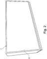
- the furniture structural element 1 in the example case after the Fig. 2 formed as a back wall of the furniture or office cabinet shown there. If the office cabinet in question, for example, freestanding is set up in a large office or acts as a room divider, the thus equipped rear wall takes over the room-side and designed as a non-woven surface element 2 the desired sound-absorbing effect at the site.
- a furniture structure element 1 which is equipped with a room-side surface element 2 and in addition a handle.
- the surface element 2 is again the predominantly smooth-surfaced form fleece made of plastic, which in the example shown after the Fig. 3 is designed as a sliding door.
- the shaped fabric may be equipped with corresponding springs 8, which are received in associated grooves 9 and can slide therein.
- a comparable tongue and groove joint with spring 8 on the form fleece and an associated groove 9 for receiving the spring 8 is in conjunction with a in the Fig. 3 also implemented spatial divider structure element 10 implemented and realized.
- the room divider structure element 10 is a so-called essay screen 10, which is placed on the furniture in question or its top plate. This is the top plate with the detail in the Fig. 3 shown groove 9, in which the spring 8 engages the space divider structure element 10 in question.
- the Fig. 4 Finally shows various variants of room divider structure elements 10, which are each made wholly or partly from the formed fabric according to the invention. It can be seen that the room divider structure elements 10 have a partially arcuate course and are equipped with additional feet 11 and optionally fastening elements 12 for attachment to an office desk shown there or for installation on the floor. In the context of the illustration, the room-side surface element 2, as it were, fills out the entire room divider structure element 10.
- viewing areas 13 can also be introduced into the room divider structure element 10 realized in this way. Such viewing areas 13 can be realized simply by virtue of the fact that the viewing area 13 has such a small material thickness D of the shaped nonwoven that it is or becomes completely or partially transparent.
- the same material thickness or material thickness D in the viewing area 13 would be 0.5 mm or even less occupies, so that this viewing area 13 is designed as a kind of partially transparent non-woven curtain.
- the viewing area 13 can also be recessed with a recessed plastic window or simply and moving. This is not shown.
Landscapes
- Engineering & Computer Science (AREA)
- Chemical & Material Sciences (AREA)
- Composite Materials (AREA)
- Mechanical Engineering (AREA)
- Textile Engineering (AREA)
- Laminated Bodies (AREA)
- Nonwoven Fabrics (AREA)
Description
- Die Erfindung betrifft ein Möbel- und/oder Raumteilerstrukturelement, mit zumindest einem raumseitigen Flächenelement, welches ganz oder teilweise als überwiegend glattflächiges Formvlies aus Kunststoff ausgebildet ist, wobei das Formvlies aus einem Faserverbundwerkstoff hergestellt ist.
- Als Möbelstrukturelement werden im Rahmen der Erfindung flächige Hauptbestandteile von Möbeln bezeichnet, die wenigstens ein raumseitiges Flächenelement aufweisen bzw. als solches ausgebildet sind. Hierbei handelt es sich beispielsweise um Seitenwände oder Rückwände von Schränken. Genauso gut kann es sich bei den Möbelstrukturelementen um eine Kopfplatte eines Möbelschrankes oder auch eine Tischplatte eines Tisches handeln. Dabei sind die betreffenden Möbelstrukturelemente bzw. raumseitigen Flächenelemente jeweils einem Raum zugewandt, in dem das aus dem betreffenden Möbelstrukturelement aufgebaute Möbelstück platziert wird.
- Grundsätzlich kann es sich bei dem Möbelstrukturelement auch um eine oder mehrere Frontplatten einer Schublade, einen freihängenden, also dem Raum zugewandten Schubladenkorpus etc. handeln. Ebenso sind Begrenzungsflächen von Theken denkbar. Bei den angesprochenen Möbeln und folglich auch den Möbelstrukturelementen handelt es sich typischerweise um Büromöbelstrukturelemente.
- Daneben bezieht sich die Erfindung auf Raumteilerstrukturelemente und insbesondere Büroraumteilerstrukturelemente. Bei solchen Raumteilerstrukturelementen handelt es sich meistens um Flächengebilde, die in Büros oder auch ansonsten zur Raumteilung eingesetzt werden, beispielsweise zur Unterteilung eines Großraumbüros in mehrere Büroarbeitsplätze. Dazu kann das betreffende Raumteilerstrukturelement freistehend auf einem Boden platziert werden oder auch als Flächengebilde ausgelegt sein, welches an im fraglichen Büro aufgestellten Büromöbeln angebracht wird. Beispielsweise mag es sich bei dem Raumteilerstrukturelement um einen sogenannten Aufsteckscreen handeln, also ein Flächengebilde, welches auf die Tischplatte eines Bürotisches oder auch die Kopfplatte eines Büroschrankes aufgesteckt wird.
- Im Rahmen der
DD 284 189 A5 - Gerade in Büros und insbesondere Großraumbüros besteht jedoch ein Bedürfnis dahingehend, die Akustik insgesamt zu verbessern. Denn in solchen Großraumbüros wird oftmals parallel von verschiedenen Leuten telefoniert und werden unterschiedliche elektrische Geräte, wie beispielsweise Drucker, bedient. Diese sämtlichen Tätigkeiten resultieren in zugehörigen Schallquellen im Innern des Großraumbüros, die unter Umständen sogar örtlich veränderbar ausgebildet sind. Das wird zunehmend als störend empfunden und senkt die Arbeitseffizienz.
- Aus diesem Grund hat man in der
DE 20 2013 011 608 U1 bereits ein Akustikwandelement beschrieben, bei dem es sich um eine geprägte und Sicken aufweisende Platte aus Filz handelt. Das Akustik-Wandelement kann als Raumteiler bzw. zur Realisierung eines Raumteilerstrukturelementes eingesetzt werden. Ebenso lässt sich hiermit ein Möbelteil realisieren und folglich ein Möbelstrukturelement und/oder eine Blende. - Das bekannte Akustikwandelement mit den geprägten Sicken ist insgesamt aus Filz hergestellt. Bei Filz handelt es sich um ein textiles Flächengebilde aus wirren und unregelmäßig verschlungenen Fasern gleichbedeutend einem Vlies. Als Fasern schlägt die Lehre nach der
DE 20 2013 011 618 U1 sowohl Chemiefasern als auch Pflanzenfasern, Wollfasern oder sogar tierische Haare und Kombinationen vor. - Durch die Ausprägung des bekannten Akustikwandelementes mit den obligatorischen Sicken ist die Herstellung relativ aufwändig. Außerdem lassen sich auf diese Weise letztlich nur Akustikwandelemente herstellen und umsetzen, die ein gewisses Größenraster aufweisen, welches der Form und Ausprägung der Sicken Rechnung trägt.
- Durch die
DE 10 2010 032 333 A1 ist ein gattungsgemäßes Möbel- und/oder Raumteilerstrukturelement bekannt geworden. Das dort beschriebene Möbelelement verfügt über eine Schallschutzvorrichtung, welche in einer Wirkverbindung mit einem Kastenmöbel steht. Die Schichten der Schallschutzvorrichtung können unter anderem aus einem Vlies hergestellt sein. Dabei werden unter anderem Vliese aus Polyester angesprochen. Weitere Einzelheiten zur Vliesherstellung lassen sich nicht entnehmen. - Vergleichbares gilt für die Lehre nach der
CH 423 136 - Die
DE 30 07 343 A1 befasst sich schließlich mit einem Verfahren zur Herstellung von Formteilen aus Faservlies. Dabei wird das Fasergut aus Fasern unter Hitze formgepresst, wobei die Wärmebehandlung dazu führt, dass der Bindungsprozess und der Formungsprozess gleichzeitig ablaufen. Als mögliche Anwendungsgebiete der bekannten Formteile aus einem Faservlies werden Rohrisolierungen oder auch Automobilanwendugnen als Bodenformteil bzw. Dachauskleidung ebenso wie Formteile für Miederwaren erwähnt. - Der Erfindung liegt das technische Problem zugrunde, ein derartiges Möbel- und/oder Raumteilerstrukturelement so weiter zu entwickeln, dass unter Berücksichtigung niedriger Herstellungskosten und einer flexiblen Flächengestaltung ein zugleich einfach aufgebautes und leichtgewichtiges Produkt zur Verfügung gestellt wird.
- Zur Lösung dieser technischen Problemstellung ist ein gattungsgemäßes Möbel- und/oder Raumteilerstrukturelement im Rahmen der Erfindung dadurch gekennzeichnet, dass der Faserverbundwerkstoff aus Kunststofffasern besteht, die mechanisch und/oder chemisch und/oder thermisch sowie bindemittelfrei miteinander verbunden sind, wobei das Formvlies ein spezifisches Gewicht von weniger als 0,6 g/cm3 aufweist.
- Im Rahmen der Erfindung ist das raumseitige Flächenelement zunächst einmal ganz oder teilweise als Formvlies aus Kunststoff ausgebildet. Bei einem solchen Formvlies handelt es sich um ein Vlies aus Kunststoff, also ein textiles Flächengebilde aus Kunststofffasern. Holzfasern oder auch Naturfasern kommen folglich ausdrücklich nicht zum Einsatz.
- Da jedoch das raumseitige Flächenelement ganz oder teilweise als überwiegend glattflächiges Formvlies aus Kunststoff ausgebildet ist, besteht die grundsätzliche und weitere Möglichkeit, das glattflächige Formvlies aus Kunststoff prinzipiell mit einem Wollvlies oder Wollfilz oder auch anderen Materialien zu ergänzen respektive zu kaschieren. Das heißt, von der Erfindung werden ausdrücklich auch raumseitige Flächenelemente mit umfasst, die beispielsweise mit einem Kern aus dem glattflächigen Formvlies aus Kunststoff ausgerüstet sind und zusätzlich eine Beschichtung bzw. Kaschierung aufweisen. Die Beschichtung bzw. Kaschierung kann ebenfalls aus einem textilen Flächenmaterial hergestellt sein, beispielsweise aus einem Vlies oder Filz. Selbst eine Kunststofffolie ist denkbar. Auch Farbkaschierungen in unterschiedlichen Farben werden von der Erfindung umfasst.
- Durch den Rückgriff auf Kunststofffasern zur Realisierung des glattflächigen Formvlieses aus Kunststoff werden einerseits hygienische Anforderungen erfüllt und können andererseits Brandschutzanforderungen umgesetzt werden. Denn solche Kunststofffasern lassen sich beispielsweise flammfest ausrüsten, was bei Holzfasern oder Naturfasern im Regelfall nicht gelingt.
- Darüber hinaus sind solche Kunststofffasern mit dem weiteren Vorteil verbunden, dass sie sich beispielsweise färben lassen oder farbig ausgelegt sein können, so dass das mit Hilfe der Kunststofffasern erzeugte erfindungsgemäße Formvlies praktisch jede denkbare Farbgestaltung annimmt oder annehmen kann. Selbstverständlich sind auch Mischfarben oder mehrfarbige Ausrüstungen oder sogar Holznachbildungen denkbar und lassen sich auf diese Weise realisieren.
- Bei dem eingesetzten Formvlies aus Kunststoff handelt es sich um ein Vlies, welches im Regelfall durch eine Wärmebehandlung der eingesetzten Kunststofffasern in praktisch jede denkbare Form gebracht werden kann. Das lässt sich im Kern durch den Rückgriff auf Kunststofffasern erklären, die bei einem entsprechenden Formprozess zumindest so weit erwärmt werden, dass sie ihren Erweichungspunkt überschritten haben. Dadurch kann das fragliche Formvlies beispielsweise in einer Presse mit Matrize und Patrize in die gewünschte Form gebracht werden. Das ist grundsätzlich bekannt, wozu auf die einleitend bereits gewürdigte
DE 30 07 343 A1 Bezug genommen sei, die sich mit dem dort bereits beschriebenen Verfahren zur Herstellung von Formteilen aus Faservlies beschäftigt. - Durch die zuvor beschriebene Herstellungsweise des eingesetzten Formvlieses aus Kunststoff im Zuge einer Wärmebehandlung der Kunststofffasern besteht darüber hinaus die Möglichkeit, das fragliche Formvlies zu prägen. Im Rahmen dieser Prägung können nicht nur Oberflächenstrukturen definiert werden, sondern es besteht auch die Möglichkeit, das Formvlies mit eingeprägten Gelenken auszurüsten, um das auf diese Weise realisierte raumseitige Flächenelement beispielsweise beweglich zu gestalten. Ebenso können Gravuren oder Drucke auf- oder eingebracht werden. Ferner kann das Formvlies mit mechanischen Befestigungs- oder Verbindungspunkten ausgerüstet werden.
- Darüber hinaus besteht die Möglichkeit, das glattflächige Formvlies aus Kunststoff nach der Erfindung mit in das Innere eingebrachten Elementen auszurüsten. Bei diesen fraglichen Elementen kann es sich um eingebrachte Verstärkungen wie Metallplatten handeln. Es ist auch möglich, im Innern des Formvlieses beispielsweise Leerrohre vorzusehen, durch welche Kabel geführt werden. Dadurch sind die Kabel nicht sichtbar. Grundsätzlich kann das glattflächige Formvlies aus Kunststoff nach der Erfindung aber auch mit Aussparungen, Hohlbohrungen im Innern etc. ausgestaltet werden, durch welche beispielsweise Kabel geführt werden, ohne dass hierzu zusätzliche Leerrohre eingebracht werden. Denn die Auslegung des Formvlieses aus Kunststoff sorgt für die erforderliche elektrische Isolation.
- Für die Realisierung des erfindungsgemäß eingesetzten Formvlieses aus Kunststoff werden nicht nur Kunststofffasern eingesetzt, sondern diese Kunststofffasern werden mechanisch und/der chemisch und/oder thermisch miteinander verfestigt. In diesem Zusammenhang ist von besonderer Bedeutung, dass die Kunststofffasern bindemittelfrei miteinander verbunden sind. Denn durch den Verzicht auf ein zusätzliches Bindemittel wird gewährleistet, dass das Formvlies im Rahmen der Erfindung praktisch nur aus den an jeweils Kreuzungs- und Berührstellen miteinander verbundenen Kunststofffasern aufgebaut ist. Dadurch erhält das Formvlies nicht nur einen besonders lockeren Aufbau, sondern werden geringe spezifische Gewichte für solche Formvliese einerseits beobachtet und weisen diese günstige Akustikeigenschaften andererseits auf.
- Tatsächlich verfügt das auf diese Weise hergestellte Formvlies erfindungsgemäß über ein spezifisches Gewicht von weniger als 0,6 g/cm3 und vorzugsweise von 0,5 g/cm3 und weniger. Geht man von einer Materialstärke einer auf diese Weise realisierten Platte von bis zu 50 mm, insbesondere bis zu ca. 30 mm und vorzugsweise in einem Bereich von 5 mm bis 20 mm aus, so bemisst sich das durchschnittliche Flächengewicht einer solchen Formvliesplatte zu in etwa 2000 g/m2 bis 3000 g/m2, was deutlich niedriger angesiedelt ist als das Plattengewicht von Holzwerkstoffplatten. Tatsächlich werden für solche Holzwerkstoffplatten Flächengewichte von 9000 g/m2 und mehr beobachtet, betragen also das 3- bis 4-fache des Formvlieses.
- Darüber hinaus zeichnen sich derartige Formvliese aus Kunststoff bzw. Kunststofffasern durch eine hohe UV-Beständigkeit aus, so dass selbst in einem lichtdurchfluteten Büro und bei einem Einsatz des Formvlieses als Frontabdeckung bei einem Möbelschrank ein Ausbleichen der Farbe des Formvlieses nicht oder kaum beobachtet wird. Sofern an dieser Stelle als Kunststofffasern vorteilhaft Polyesterfasern bzw. PET-Fasern eingesetzt werden, neigt das fragliche Formvlies auch nicht zu elektrostatischen Aufladungen. Denn Polyesterfasern verfügen über eine äußerst geringe Fähigkeit sich elektrostatisch aufzuladen. Das ist von besonderer Bedeutung vor dem Hintergrund, dass das fragliche Formvlies insbesondere zur Herstellung von Büromöbeln zum Einsatz kommt und elektrostatische Aufladung in Verbindung mit in Büros eingesetzten Computern, Computerlaufwerken oder auch Druckern ausdrücklich zu vermeiden sind.
- Hinzukommt, dass sich solche vorteilhaft eingesetzten PET- bzw. Polyesterfasern besonders einfach und dauerhaft einfärben lassen, wie dies zuvor bereits beschrieben wurde. Außerdem ist die Feuerschutzbeständigkeit derjenigen von Naturfasern oder Holzfasern deutlich überlegen. Denn Formvliese bestehen üblicherweise die Brandprüfung nach DIN EN 1021 Teil 1 und 2, welche die Endzündbarkeit von Polstermöbeln bewertet. Dabei kann der Brandwiderstand insgesamt noch durch Zumischung von brandhemmenden Fasern oder eine Beschichtung der eingesetzten Kunststofffasern erhöht werden.
- Durch den Einsatz von vorteilhaft Polyesterfasern als Kunststofffasern bei der Realisierung des Formvlieses werden eine insgesamt robuste Gestaltung und ein entsprechendes Material zur Verfügung gestellt, dem mehrere Jahrzehnte Lebensdauer prognostiziert werden können. Als besondere weitere Eigenschaft für das Formvlies beobachtet man, dass die eingesetzten Formvliese im an dieser Stelle relevanten Frequenzbereich von 100 Hz bis 5000 Hz einen Schallabsorptionsgrad von wenigstens 0,5 erreichen. Bei einem solchen Schallabsorptionsgrad werden wenigstens 50 % der auftreffenden Schallenergie absorbiert und im Maximum 50 % der Schallenergie reflektiert. Das gilt im angegebenen Frequenzbereich von 100 Hz bis 5000 Hz, der nahezu ausschließlich in Büroräumen beobachtet wird.
- Diese besonderen akustischen Eigenschaften lassen sich primär darauf zurückführen, dass die Kunststofffasern bindemittelfrei miteinander verbunden werden. Denn hierdurch bilden die das erfindungsgemäße Formvlies definierenden Kunststofffasern ein räumliches Netzwerk aus den jeweils in lediglich Kreuzungs- und Berührstellen miteinander verbundenen Kunststofffasern mit dazwischen verbleibenden Freiräumen in chaotischer Anordnung. Dieses stellt eine optimale Oberfläche zur Absorption von auftreffendem Schall dar, und zwar auch und insbesondere dann, wenn das Formvlies überwiegend glattflächig ausgebildet ist. Das heißt, das Einbringen von Sicken, wie sie der Stand der Technik nach der
DE 20 2013 011 608 U1 als gleichsam unverzichtbar ansieht, ist ausdrücklich nicht erforderlich, so dass sich die erfindungsgemäß verwendeten Formvliese in jeder denkbaren Größe und Gestalt einfach, schnell und preisgünstig herstellen lassen. - Die bindemittelfreie Verbindung der Kunststofffasern und insbesondere Polyesterfasern wird im Regelfall so vorgenommen und umgesetzt, dass die jeweiligen Kunststofffasern zunächst mit einer Weichmacherlösung benetzt und dann bei einer erhöhten Temperatur miteinander verklebt werden. Als erhöhte Temperatur empfiehlt die Erfindung Temperaturen im Bereich von ca. 80 °C bis 160 °C. Bei solchen Temperaturen wird im Allgemeinen der Schmelzpunkt der eingesetzten Kunststofffasern erreicht oder geringfügig überschritten, so dass bei einem anschließenden Pressvorgang unter Berücksichtigung der angegebenen erhöhten Temperatur die einzelnen Kunststofffasern ohne zusätzlich eingebrachtes Bindemittel an ihren Kreuzungs- und Berührstellen wunschgemäß miteinander verbunden werden. Eine solche Vorgehensweise ist zwar grundsätzlich durch die
DE 1 237 057 A oder auch dieDE 1 469 347 A bekannt, allerdings bisher nicht in Verbindung mit und zur Herstellung von Möbel- und/oder Raumstrukturelementen zum Einsatz gekommen. - Selbstverständlich kann es sich bei den eingesetzten Kunststofffasern auch um sogenannte Bikomponentenfasern handeln. In diesem Fall kommen vorteilhaft Co-Polyesterfasern zum Einsatz, die mit einem Polyesterkern einerseits und einer Ummantelung mit einem Polyester geringeren Schmelzpunktes andererseits ausgerüstet sind. Auch Materialkombinationen unterschiedlicher Kunststoffe und hieraus hergestellter Bikomponentenfasern werden ausdrücklich von der Erfindung mit umfasst.
- Schließlich lässt sich das Formvlies mit eingebrachten Schnitten ausrüsten. Dadurch kann mit Hilfe des Formvlieses ein flexibler bogenförmiger Verlauf des Flächenelementes realisiert werden, ähnlich einem Rollladen. Um dies im Detail zu erreichen, werden die fraglichen Schnitte im Allgemeinen quer zur Längserstreckung des Formvlieses in dieses eingebracht. Außerdem hat es sich bewährt, die jeweiligen Schnitte in gleichem Abstand zu setzen. Als Schnitte können sowohl gerade Schnitte als auch V-förmige Schnitte zur Anwendung kommen. Ein V-förmiger Einschnitt oder V-förmige Einschnitte empfehlen sich für den Fall, dass das solchermaßen behandelte und überwiegend glattflächige Formvlies aus Kunststoff beispielsweise gefaltet oder abgewinkelt werden soll.
- Dadurch wird auch im Bereich eines durchgängigen Formvliesrückens eine optisch gleichmäßige Ausbildung erreicht.
- Zum Einbringen der Schnitte wird man meistens so vorgehen, dass die Schnitte bis in eine Schnitttiefe des Formvlieses reichen, die maximal bis ca. 100 % und regelmäßig maximal bis ca. 95 % und insbesondere maximal bis ca. 90 %, vorzugsweise bis ca. 80 % der Materialstärke des Formvlieses beträgt. Das heißt, bei dem Schnitt in das Formvlies verbleibt der zuvor bereits angesprochene und durchgängige Formvliesrücken. Dieser Formvliesrücken übernimmt auf diese Weise gleichsam die Funktion eines Verbinders für die einzelnen hierdurch hergestellten und gegeneinander bewegbaren Lamellen. Dadurch lässt sich auf diese Weise mit Hilfe eines solchen Formvlieses beispielsweise eine Rolloabdeckung bei einem Büroschrank oder allgemein in einem Schrank realisieren, die nicht nur einem vorgegebenen bogenförmigen Verlauf innerhalb von Schienen folgt, sondern durch ihre Materialwahl auch und insbesondere auftreffenden Schall besonders wirkungsvoll dämpft und absorbiert.
- Tatsächlich ist aufgrund der zuvor bereits beschriebenen und erreichten Schallabsorptionsgrade damit zu rechnen, dass bei einer Ausrüstung einzelner oder sämtlicher Möbelstücke in einem Großraumbüro mit zumindest einem erfindungsgemäß gestalteten Möbelstrukturelement der im Großraumbüro herrschende Schallpegel deutlich gesenkt wird. Beispielsweise wird man Reduzierungen des Schallpegels um ein Drittel bis in etwa zur Hälfte erreichen können, so dass die Arbeitsatmosphäre insgesamt und auch die Arbeitseffizienz deutlich verbessert sind. Hierin sind die wesentlichen Vorteile zu sehen.
- Im Folgenden wird die Erfindung anhand einer lediglich ein Ausführungsbeispiel darstellenden Zeichnung näher erläutert; es zeigen:
- Fig. 1
- einen Schrank und insbesondere Büroschrank mit einer frontseitigen Rolloabdeckung, die als erfindungsgemäßes Möbelstrukturelement ausgelegt ist,
- Fig. 2
- einen anderen Büroschrank, bei dem eine Rückwand als erfindungsgemäßes Möbelstrukturelement ausgeführt ist,
- Fig. 3
- einen Büroschrank, welcher eine frontseitige und als erfindungsgemäßes Möbelstrukturelement ausgeführte Schiebetür ebenso wie ein aufgesetztes Raumteilerstrukturelement nach der Erfindung aufweist sowie
- Fig. 4
- verschiedene Varianten anderer Raumteilerstrukturelemente entsprechend der Erfindung.
- In der
Fig. 1 ist ein Möbelstück dargestellt, bei dem es sich im Ausführungsbeispiel um ein Büromöbelstück, nämlich einen beispielhaft gezeigten Aktenschrank oder allgemein ein Büroschrank handelt. Das Möbelstück ist mit einem Möbelstrukturelement 1 ausgerüstet, bei dem es sich im Ausführungsbeispiel nach derFig. 1 um eine Frontplatte bzw. um eine frontseitige Abdeckung des Möbelstückes respektive des Aktenschrankes handelt. Bei dem Möbelstück nach derFig. 2 ist das Möbelstrukturelement 1 als Rückwand des dort dargestellten Büroschrankes ausgelegt. Grundsätzlich kann es sich bei dem Möbelstrukturelement 1 aber auch um eine Seitenwand oder sogar eine Kopfplatte des Schrankes handeln. Das ist jedoch im Detail nicht gezeigt. Das Möbelstrukturelement 1 verfügt über ein raumseitiges Flächenelement 2. - Tatsächlich setzt sich das Möbelstrukturelement 1 bzw. die frontseitige Abdeckung nach der
Fig. 1 aus einerseits dem raumseitigen Flächenelement 2 und andererseits zwei randseitigen Schienen 3 zusammen. Die beiden randseitigen Schienen 3 begrenzen das raumseitige Flächenelement 2 und dienen zu seiner Bedienung bzw. Beaufschlagung, wie nachfolgend noch näher erläutert wird. - Tatsächlich handelt es sich bei dem raumseitigen Flächenelement 2 im Rahmen der Erfindung um ein überwiegend glattflächiges Formvlies aus Kunststoff, wie es ergänzend in der
Fig. 1 perspektivisch dargestellt ist. Bei dem fraglichen Formvlies aus Kunststoff handelt es sich um ein solches, welches mit eingebrachten Schnitten 4 ausgerüstet ist. Die fraglichen Schnitte 4 sind jeweils quer zur Längserstreckung des Formvlieses in dieses eingebracht, und zwar in jeweils gleichem Abstand zueinander und ausgehend von einer gemeinsamen Oberfläche des Formvlieses. - Tatsächlich ist das Formvlies insgesamt flächig und überwiegend glattflächig ausgelegt und verfügt über einen mehr oder minder plattenförmigen Charakter. Die einzelnen Schnitte 4 werden nun in das Formvlies ausweislich der
Fig. 1 so weit eingebracht, dass sie zu einer Schnitttiefe S korrespondieren, welche im Ausführungsbeispiel maximal 90 % bzw. maximal 80 % einer Materialstärke D des Formvlieses beträgt. Auf diese Weise wird im Bereich der Schnitte 4 ein durchgängiger Formvliesrücken 5 zur Verfügung gestellt und verbleibt, welcher dafür sorgt, dass die auf diese Weise definierten einzelnen Lamellen 6 mit Hilfe des Formvliesrückens 5 miteinander verbunden sind. - Die einzelnen Lamellen 6 lassen sich gegeneinander verschwenken, so dass auf diese Weise das Formvlies in einen flexiblen bogenförmigen Verlauf des auf diese Weise realisierten Flächenelementes 2 gebracht werden kann, wie dies in der
Fig. 1 angedeutet ist. Dadurch kann automatisch und gleichsam zwanglos ein Abdeckrollo bzw. Querrollo als frontseitige Abdeckung 1 für den in derFig. 1 dargestellten Büroschrank bzw. Aktenschrank zur Verfügung gestellt werden. - Da das Formvlies insgesamt aus einem Faserverbundwerkstoff aus Kunststofffasern hergestellt ist und im Übrigen die einzelnen Kunststofffasern bindemittelfrei miteinander verbunden sind, verfügt das Formvlies und folglich die frontseitige Abdeckung 1 bzw. das an dieser Stelle realisierte Querrollo oder Abdeckrollo über eine zwar überwiegend glattflächige Oberfläche, die jedoch insgesamt zerklüftet ausgebildet ist. Denn der Verzicht auf ein Bindemittel zur Verbindung der einzelnen Kunststofffasern untereinander führt dazu, dass die Kunststofffasern lediglich an Kreuzungs- und Berührstellen miteinander verbunden sind, wie dies einleitend bereits beschrieben wurde.
- Dadurch lässt sich ein Absorptionsgrad von 0,5 und mehr zur Verfügung stellen, so dass im Regelfall mehr als 50 % der auf die fragliche Abdeckung 1 auftreffenden Schallenergie von dieser absorbiert wird. Dadurch sorgt das auf diese Weise realisierte Möbelstück zugleich für eine wirksame Reduzierung des Schallpegels am Aufstellungsort und insbesondere in dem zugehörigen Raum, in welchem das fragliche Möbelstück platziert wird. Das Formvlies verfügt insgesamt über eine Materialstärke bzw. Materialdicke D, die bis zu 50 mm betragen kann. Im Regelfall liegt die fragliche Materialdicke bzw. Materialstärke D im Bereich von 5 mm bis 20 mm. Bei den eingesetzten Kunststofffasern zur Realisierung des Formvlieses handelt es sich typischerweise um Polyester bzw. PET-Fasern, die nicht nur brandhemmend ausgerüstet werden können, sondern sich auch in praktisch jeder beliebigen Farbe ausrüsten lassen. Außerdem neigen solche Polyesterfasern praktisch nicht zu einer elektrostatischen Aufladung und sind folglich für den Einsatzzweck bei der Ausrüstung von beispielsweise Großraumbüros prädestiniert.
- Hinzukommt, dass solche Formvliese über ein geringes spezifisches Gewicht und auch ein geringes Flächengewicht im Bereich von ca. 2000 g/m2 bis 3000 g/m2 verfügen, so dass ein entsprechend aufgebauter Büroschrank oder allgemein ein entsprechend aufgebautes Büromöbelstück über ein verringertes Gewicht im Vergleich zu einem ähnlich aufgebauten Möbelstück aus Holz oder Holzwerkstoffplatten verfügt.
- Im Rahmen der Variante nach der
Fig. 2 ist das Möbelstrukturelement 1 mit einem raumseitigen Flächenelement 2 ausgerüstet, welches in diesem Beispielfall von seiner Ausdehnung her dem Möbelstrukturelement 1 entspricht. Tatsächlich ist das Möbelstrukturelement 1 im Beispielfall nach derFig. 2 als Rückwand des dort dargestellten Möbelstückes bzw. Büroschrankes ausgebildet. Sofern der fragliche Büroschrank beispielsweise freistehend in einem Großraumbüro aufgestellt wird oder als Raumteiler fungiert, übernimmt die auf diese Weise ausgerüstete Rückwand mit dem raumseitigen und als Formvlies ausgelegten Flächenelement 2 die gewünschte schallabsorbierende Wirkung am Aufstellungsort. - Im Rahmen der
Fig. 3 ist eine weitere Variante dargestellt. Hier beobachtet man ein Möbelstrukturelement 1, welches mit einem raumseitigen Flächenelement 2 sowie zusätzlich einer Handhabe ausgerüstet ist. Bei dem Flächenelement 2 handelt es sich erneut um das überwiegend glattflächige Formvlies aus Kunststoff, welches im dargestellten Beispielfall nach derFig. 3 als Schiebetür ausgebildet ist. Dazu mag das Formvlies mit entsprechenden Federn 8 ausgerüstet sein, die in zugehörigen Nuten 9 aufgenommen werden und hierin gleiten können. Eine vergleichbare Nut-Federverbindung mit Feder 8 am Formvlies und einer zugehörigen Nut 9 zur Aufnahme der Feder 8 ist in Verbindung mit einem in derFig. 3 ebenfalls dargestellten Raumteilerstrukturelement 10 umgesetzt und realisiert. - Bei dem Raumteilerstrukturelement 10 handelt es sich um einen sogenannten Aufsatzschirm 10, der auf das fragliche Möbelstück bzw. dessen Kopfplatte aufgesetzt ist. Dazu ist die Kopfplatte mit der im Detail in der
Fig. 3 dargestellten Nut 9 ausgerüstet, in welche die Feder 8 am fraglichen Raumteilerstrukturelement 10 eingreift. - Die
Fig. 4 zeigt schließlich verschiedene Varianten von Raumteilerstrukturelementen 10, die jeweils ganz oder teilweise aus dem erfindungsgemäßen Formvlies hergestellt sind. Man erkennt, dass die Raumteilerstrukturelemente 10 einen teils bogenförmigen Verlauf aufweisen und mit zusätzlichen Füßen 11 und gegebenenfalls Befestigungselementen 12 zur Anbringung an einem dort dargestellten Bürotisch respektive zur Aufstellung auf dem Boden ausgerüstet sind. Im Rahmen der Darstellung füllt das raumseitige Flächenelement 2 gleichsam das gesamte Raumteilerstrukturelement 10 aus. - Dabei versteht es sich, dass in das solchermaßen realisierte Raumteilerstrukturelement 10 grundsätzlich auch Sichtbereiche 13 eingebracht werden können. Solche Sichtbereiche 13 lassen sich einfach dadurch realisieren, dass der Sichtbereich 13 über eine so geringe Materialstärke D des Formvlieses verfügt, dass dieses ganz oder teilweise durchsichtig ist oder wird.
- Während man beispielsweise für das Formvlies und das entsprechend gestaltete Raumteilerstrukturelement 10 überwiegend mit einer Materialdicke D von im Minimum 10 mm arbeitet, ist es denkbar, dass dieselbe Materialstärke bzw. Materialdicke D im Sichtbereich 13 Werte von 0,5 mm oder noch weniger einnimmt, so dass dieser Sichtbereich 13 gleichsam wie ein teilweise durchsichtiger Vliesvorhang gestaltet ist. Selbstverständlich kann der Sichtbereich 13 auch mit einem eingelassenen Kunststofffenster oder schlicht und ergreifend ausgespart werden. Das ist jedoch nicht dargestellt.
Claims (11)
- Möbel- und/oder Raumteilerstrukturelement (1; 10), mit zumindest einem raumseitigen Flächenelement (2), welches ganz oder teilweise als überwiegend glattflächiges Formvlies aus Kunststoff ausgebildet ist, wobei das Formvlies aus einem Faserverbundwerkstoff hergestellt ist, dadurch gekennzeichnet, dass- der Faserverbundwerkstoff aus Kunststofffasern besteht, die mechanisch und/oder chemisch und/oder thermisch sowie bindemittelfrei miteinander verbunden sind, wobei- das Formvlies ein spezifisches Gewicht von weniger als 0,6 g/cm3 aufweist.
- Element nach Anspruch 1, dadurch gekennzeichnet, dass als Kunststofffasern PET-Fasern eingesetzt werden.
- Element nach Anspruch 1 oder 2, dadurch gekennzeichnet, dass das Formvlies plattenförmig und ggf. räumlich strukturiert ausgebildet ist.
- Element nach einem der Ansprüche 1 bis 3, dadurch gekennzeichnet, dass das Formvlies eine Materialstärke (D) bis ca. 50 mm, insbesondere bis ca. 30 mm und vorzugsweise von 5 mm bis 20 mm aufweist
- Element nach einem der Ansprüche 1 bis 4, dadurch gekennzeichnet, dass das Formvlies mit eingebrachten Schnitten (4) ausgerüstet ist, um beispielsweise einen flexiblen bogenförmigen Verlauf des Flächenelementes (2) zu realisieren.
- Element nach Anspruch 5, dadurch gekennzeichnet, dass die Schnitte (4) quer zur Längserstreckung des Formvlieses verlaufen.
- Element nach Anspruch 5 oder 6, dadurch gekennzeichnet, dass die Schnitte (4) bis in eine Schnitttiefe (S) des Formvlieses reichen, die bis maximal ca. 100 %, insbesondere bis maximal ca. 95 % und vorzugsweise bis maximal ca. 90 % sowie ganz besonders bevorzugt bis maximal ca. 80 % der Materialstärke (D) des Formvlieses beträgt, so dass ein durchgängiger Formvliesrücken (5) verbleibt.
- Element nach einem der Ansprüche 1 bis 7, dadurch gekennzeichnet, dass das Formvlies farbig ausgelegt ist.
- Verwendung von Formvliesen zur Herstellung von Möbel- und/oder Raumstrukturelementen (1; 10) nach einem der Ansprüche 1 bis 8, wobei das Formvlies aus Kunststofffasern hergestellt wird, die an Kreuzungs- und Berührstellen miteinander verbunden werden.
- Verwendung nach Anspruch 9, dadurch gekennzeichnet, dass die Kunststofffasern bindemittelfrei miteinander verbunden werden, indem sie mit einer Weichmacherlösung benetzt und bei erhöhter Temperatur miteinander verklebt werden.
- Verwendung nach Anspruch 10, dadurch gekennzeichnet, dass die Kunststofffasern bei einer Temperatur im Bereich von 80 °C bis 160 °C miteinander verklebt werden.
Priority Applications (3)
| Application Number | Priority Date | Filing Date | Title |
|---|---|---|---|
| EP16168093.9A EP3241462B1 (de) | 2016-05-03 | 2016-05-03 | Möbel- und/oder raumteilerstrukturelement |
| PL16168093T PL3241462T3 (pl) | 2016-05-03 | 2016-05-03 | Element strukturalny mebla i/lub ścianki działowej |
| DK16168093.9T DK3241462T3 (en) | 2016-05-03 | 2016-05-03 | Furniture and / or room divider structure element |
Applications Claiming Priority (1)
| Application Number | Priority Date | Filing Date | Title |
|---|---|---|---|
| EP16168093.9A EP3241462B1 (de) | 2016-05-03 | 2016-05-03 | Möbel- und/oder raumteilerstrukturelement |
Publications (2)
| Publication Number | Publication Date |
|---|---|
| EP3241462A1 EP3241462A1 (de) | 2017-11-08 |
| EP3241462B1 true EP3241462B1 (de) | 2018-04-18 |
Family
ID=55910837
Family Applications (1)
| Application Number | Title | Priority Date | Filing Date |
|---|---|---|---|
| EP16168093.9A Revoked EP3241462B1 (de) | 2016-05-03 | 2016-05-03 | Möbel- und/oder raumteilerstrukturelement |
Country Status (3)
| Country | Link |
|---|---|
| EP (1) | EP3241462B1 (de) |
| DK (1) | DK3241462T3 (de) |
| PL (1) | PL3241462T3 (de) |
Cited By (4)
| Publication number | Priority date | Publication date | Assignee | Title |
|---|---|---|---|---|
| EP3808220A1 (de) | 2019-10-17 | 2021-04-21 | Klöber GmbH | Möbel aus einem faserverbundwerkstoff |
| DE102020213543A1 (de) | 2020-10-28 | 2022-04-28 | Sedus Stoll Aktiengesellschaft | Verfahren zur Herstellung einer einstückigen Faserverbundstruktur aus zumindest einer Faserverbundmatte sowie Faserverbundstruktur |
| DE102020213546A1 (de) | 2020-10-28 | 2022-04-28 | Sedus Stoll Aktiengesellschaft | Verfahren zur Herstellung eines Raumteilers aus Faserverbundmatten, Raumteilersystem sowie Tisch |
| DE102020213545A1 (de) | 2020-10-28 | 2022-04-28 | Sedus Stoll Aktiengesellschaft | Verfahren zur Herstellung einer einstückigen Sitzschale aus einer Faserverbundmatte zur Verwendung in einem Sitzmöbel sowie Sitzmöbel |
Families Citing this family (2)
| Publication number | Priority date | Publication date | Assignee | Title |
|---|---|---|---|---|
| EP3571958B1 (de) | 2018-05-22 | 2020-12-09 | Fleischer Büromöbelwerk GmbH & Co. KG | Möbelansatzwand, insbesondere tischmöbelansatzwand |
| EP3575507A1 (de) | 2018-05-28 | 2019-12-04 | CEKA GmbH Co. KG | Akustikstellwand |
Citations (10)
| Publication number | Priority date | Publication date | Assignee | Title |
|---|---|---|---|---|
| CH423136A (de) | 1964-12-21 | 1966-10-31 | P & A Marghitola Geb | Verfahren zur Herstellung von Bau- und Möbelteilen mit winklig aneinanderstossenden Wänden und nach diesem Verfahren hergestellte Bau- und Möbelteile |
| DE1469347A1 (de) | 1964-05-25 | 1968-12-19 | Filzfabrik Fulda Gmbh | Verfahren zum Herstellen von verfestigten bindemittelfreien Vliesstoffen |
| DE1237057B (de) | 1964-03-31 | 1974-03-07 | ||
| DE3007343A1 (de) | 1980-02-27 | 1981-09-10 | Johann Borgers Gmbh & Co Kg, 4290 Bocholt | Verfahren zur herstellung von formteilen aus faservlies |
| US20030160551A1 (en) | 2002-02-28 | 2003-08-28 | Beyer Peter J. | Storage cabinet with movable door |
| US20090117801A1 (en) | 2007-11-05 | 2009-05-07 | Flack Leanne O | Non-woven composite office panel |
| DE102010032333A1 (de) | 2010-07-19 | 2012-01-19 | Jochen Renz | Möbelelement mit einer Einrichtung zur Schallabsorption |
| WO2014063263A1 (de) | 2012-10-23 | 2014-05-01 | Vitra Patente Ag | Bausatz aus wandelementen und zwischen solchen einzufügenden verbindern zur errichtung von raumteilern |
| EP2947255A1 (de) | 2014-05-22 | 2015-11-25 | Vitra Patente AG | Tür für ein korpusmöbel und korpusmöbel mit einer solchen tür |
| EP3150086A1 (de) | 2015-09-30 | 2017-04-05 | Vitra Patente AG | Möbelrohling, möbel und verfahren zum herstellen eines möbels |
Family Cites Families (3)
| Publication number | Priority date | Publication date | Assignee | Title |
|---|---|---|---|---|
| DD284189A5 (de) | 1989-05-24 | 1990-11-07 | Veb Wtz Der Holzverarbeitenden Industrie,Dd | Verfahren zur herstellung eines duennen biegbaren holzpartikelwerkstoffs |
| DE202013011608U1 (de) | 2013-12-23 | 2014-02-20 | REISS Büromöbel GmbH | Akustikwandelement |
| DE202013011618U1 (de) | 2013-12-27 | 2014-02-20 | Ramon Kranaster | Wasserspray produzierender Duschschlauch |
-
2016
- 2016-05-03 EP EP16168093.9A patent/EP3241462B1/de not_active Revoked
- 2016-05-03 DK DK16168093.9T patent/DK3241462T3/en active
- 2016-05-03 PL PL16168093T patent/PL3241462T3/pl unknown
Patent Citations (10)
| Publication number | Priority date | Publication date | Assignee | Title |
|---|---|---|---|---|
| DE1237057B (de) | 1964-03-31 | 1974-03-07 | ||
| DE1469347A1 (de) | 1964-05-25 | 1968-12-19 | Filzfabrik Fulda Gmbh | Verfahren zum Herstellen von verfestigten bindemittelfreien Vliesstoffen |
| CH423136A (de) | 1964-12-21 | 1966-10-31 | P & A Marghitola Geb | Verfahren zur Herstellung von Bau- und Möbelteilen mit winklig aneinanderstossenden Wänden und nach diesem Verfahren hergestellte Bau- und Möbelteile |
| DE3007343A1 (de) | 1980-02-27 | 1981-09-10 | Johann Borgers Gmbh & Co Kg, 4290 Bocholt | Verfahren zur herstellung von formteilen aus faservlies |
| US20030160551A1 (en) | 2002-02-28 | 2003-08-28 | Beyer Peter J. | Storage cabinet with movable door |
| US20090117801A1 (en) | 2007-11-05 | 2009-05-07 | Flack Leanne O | Non-woven composite office panel |
| DE102010032333A1 (de) | 2010-07-19 | 2012-01-19 | Jochen Renz | Möbelelement mit einer Einrichtung zur Schallabsorption |
| WO2014063263A1 (de) | 2012-10-23 | 2014-05-01 | Vitra Patente Ag | Bausatz aus wandelementen und zwischen solchen einzufügenden verbindern zur errichtung von raumteilern |
| EP2947255A1 (de) | 2014-05-22 | 2015-11-25 | Vitra Patente AG | Tür für ein korpusmöbel und korpusmöbel mit einer solchen tür |
| EP3150086A1 (de) | 2015-09-30 | 2017-04-05 | Vitra Patente AG | Möbelrohling, möbel und verfahren zum herstellen eines möbels |
Non-Patent Citations (1)
| Title |
|---|
| "Ein Auszug zum Thema Polyethylenterephtalat", ENZYKLOPÄDIE WIKIPEDIA, 9 April 2016 (2016-04-09), Retrieved from the Internet <URL:https://de.wikipedia.orq/wiki/Polyethylenterephthalat> |
Cited By (8)
| Publication number | Priority date | Publication date | Assignee | Title |
|---|---|---|---|---|
| EP3808220A1 (de) | 2019-10-17 | 2021-04-21 | Klöber GmbH | Möbel aus einem faserverbundwerkstoff |
| DE102019128083A1 (de) * | 2019-10-17 | 2021-04-22 | Klöber GmbH | Möbel aus einem Faserverbundwerkstoff |
| DE102020213543A1 (de) | 2020-10-28 | 2022-04-28 | Sedus Stoll Aktiengesellschaft | Verfahren zur Herstellung einer einstückigen Faserverbundstruktur aus zumindest einer Faserverbundmatte sowie Faserverbundstruktur |
| DE102020213546A1 (de) | 2020-10-28 | 2022-04-28 | Sedus Stoll Aktiengesellschaft | Verfahren zur Herstellung eines Raumteilers aus Faserverbundmatten, Raumteilersystem sowie Tisch |
| DE102020213545A1 (de) | 2020-10-28 | 2022-04-28 | Sedus Stoll Aktiengesellschaft | Verfahren zur Herstellung einer einstückigen Sitzschale aus einer Faserverbundmatte zur Verwendung in einem Sitzmöbel sowie Sitzmöbel |
| EP3991603A1 (de) | 2020-10-28 | 2022-05-04 | Sedus Stoll AG | Verfahren zur herstellung einer einstückigen sitzschale aus einer faserverbundmatte zur verwendung in einem sitzmöbel sowie sitzmöbel |
| EP3991954A2 (de) | 2020-10-28 | 2022-05-04 | Sedus Stoll AG | Verfahren zur herstellung einer einstückigen faserverbundstruktur aus zumindest einer faserverbundmatte sowie faserverbundstruktur |
| EP4000463A1 (de) | 2020-10-28 | 2022-05-25 | Sedus Stoll AG | Verfahren zur herstellung eines raumteilers aus faserverbundmatten, raumteilersystem sowie tisch |
Also Published As
| Publication number | Publication date |
|---|---|
| DK3241462T3 (en) | 2018-07-30 |
| EP3241462A1 (de) | 2017-11-08 |
| PL3241462T3 (pl) | 2018-10-31 |
Similar Documents
| Publication | Publication Date | Title |
|---|---|---|
| EP3241462B1 (de) | Möbel- und/oder raumteilerstrukturelement | |
| DE60120678T2 (de) | Nachgiebiges strukturelles paneel | |
| DE202016100525U1 (de) | Schallabsorptionslement | |
| DE202012011048U1 (de) | Platte mit außenseitiger Nutzschicht | |
| AT520393B1 (de) | Schallabsorptionselement | |
| EP2963199B1 (de) | Schalldämmende platte | |
| DE102012022490A1 (de) | Platte mit außenseitiger Nutzschicht | |
| EP2787146B1 (de) | Verfahren zur Herstellung einer Platte mit einer textilen Nutzschicht | |
| DE202016008994U1 (de) | Möbel- und/oder Raumteilerstrukturelement | |
| DE102010032333A1 (de) | Möbelelement mit einer Einrichtung zur Schallabsorption | |
| DE202007005712U1 (de) | Wandelement | |
| EP3003707B1 (de) | Akustikmodul | |
| DE3134396A1 (de) | Laminatstruktur fuer akustische anwendungen und verfahren zu ihrer herstellung | |
| EP3568537A1 (de) | Akustikdämmplatte | |
| DE202011103090U1 (de) | Raumklima-förderliche Geräusch-Absorber | |
| EP3575507A1 (de) | Akustikstellwand | |
| DE202012012559U1 (de) | Dämmplattenanordnung, insbesondere Stufen-Dämmplatte, Trockenestrich und Dämmvorrichtung | |
| EP3571958B1 (de) | Möbelansatzwand, insbesondere tischmöbelansatzwand | |
| DE2506056A1 (de) | Anwendung elektrostatisch mit fasern beflockter gegenstaende als veranschaulichungs- oder gestaltungsmittel | |
| DE10052070A1 (de) | Mobile Trennwand | |
| DE102013002800A1 (de) | Akustikplatte | |
| WO2024216316A1 (de) | Akustikdämmplatte mit seitenprofil für die montage | |
| CH719045A9 (de) | Schallabsorbierendes Akustikelement mit Schallabsorber. | |
| DE202015102968U1 (de) | Geräusch-Absorber | |
| DE202011002963U1 (de) | Absorbermodul und Rauminstallation |
Legal Events
| Date | Code | Title | Description |
|---|---|---|---|
| REG | Reference to a national code |
Ref country code: DE Ref legal event code: R138 Ref document number: 202016008994 Country of ref document: DE Free format text: GERMAN DOCUMENT NUMBER IS 502016000886 |
|
| STAA | Information on the status of an ep patent application or granted ep patent |
Free format text: STATUS: EXAMINATION IS IN PROGRESS |
|
| PUAI | Public reference made under article 153(3) epc to a published international application that has entered the european phase |
Free format text: ORIGINAL CODE: 0009012 |
|
| 17P | Request for examination filed |
Effective date: 20160722 |
|
| AK | Designated contracting states |
Kind code of ref document: A1 Designated state(s): AL AT BE BG CH CY CZ DE DK EE ES FI FR GB GR HR HU IE IS IT LI LT LU LV MC MK MT NL NO PL PT RO RS SE SI SK SM TR |
|
| AX | Request for extension of the european patent |
Extension state: BA ME |
|
| RIC1 | Information provided on ipc code assigned before grant |
Ipc: A47B 96/20 20060101AFI20171106BHEP Ipc: E06B 9/11 20060101ALI20171106BHEP Ipc: B29C 53/04 20060101ALN20171106BHEP |
|
| GRAP | Despatch of communication of intention to grant a patent |
Free format text: ORIGINAL CODE: EPIDOSNIGR1 |
|
| STAA | Information on the status of an ep patent application or granted ep patent |
Free format text: STATUS: GRANT OF PATENT IS INTENDED |
|
| GRAS | Grant fee paid |
Free format text: ORIGINAL CODE: EPIDOSNIGR3 |
|
| INTG | Intention to grant announced |
Effective date: 20171220 |
|
| GRAA | (expected) grant |
Free format text: ORIGINAL CODE: 0009210 |
|
| STAA | Information on the status of an ep patent application or granted ep patent |
Free format text: STATUS: THE PATENT HAS BEEN GRANTED |
|
| AK | Designated contracting states |
Kind code of ref document: B1 Designated state(s): AL AT BE BG CH CY CZ DE DK EE ES FI FR GB GR HR HU IE IS IT LI LT LU LV MC MK MT NL NO PL PT RO RS SE SI SK SM TR |
|
| REG | Reference to a national code |
Ref country code: GB Ref legal event code: FG4D Free format text: NOT ENGLISH |
|
| REG | Reference to a national code |
Ref country code: CH Ref legal event code: EP |
|
| REG | Reference to a national code |
Ref country code: AT Ref legal event code: REF Ref document number: 989492 Country of ref document: AT Kind code of ref document: T Effective date: 20180515 |
|
| REG | Reference to a national code |
Ref country code: IE Ref legal event code: FG4D Free format text: LANGUAGE OF EP DOCUMENT: GERMAN |
|
| REG | Reference to a national code |
Ref country code: DE Ref legal event code: R096 Ref document number: 502016000886 Country of ref document: DE |
|
| PG25 | Lapsed in a contracting state [announced via postgrant information from national office to epo] |
Ref country code: RS Free format text: LAPSE BECAUSE OF FAILURE TO SUBMIT A TRANSLATION OF THE DESCRIPTION OR TO PAY THE FEE WITHIN THE PRESCRIBED TIME-LIMIT Effective date: 20180418 |
|
| REG | Reference to a national code |
Ref country code: DK Ref legal event code: T3 Effective date: 20180719 |
|
| REG | Reference to a national code |
Ref country code: NL Ref legal event code: FP |
|
| REG | Reference to a national code |
Ref country code: CH Ref legal event code: NV Representative=s name: KELLER AND PARTNER PATENTANWAELTE AG, CH |
|
| REG | Reference to a national code |
Ref country code: LT Ref legal event code: MG4D |
|
| PG25 | Lapsed in a contracting state [announced via postgrant information from national office to epo] |
Ref country code: NO Free format text: LAPSE BECAUSE OF FAILURE TO SUBMIT A TRANSLATION OF THE DESCRIPTION OR TO PAY THE FEE WITHIN THE PRESCRIBED TIME-LIMIT Effective date: 20180718 Ref country code: SE Free format text: LAPSE BECAUSE OF FAILURE TO SUBMIT A TRANSLATION OF THE DESCRIPTION OR TO PAY THE FEE WITHIN THE PRESCRIBED TIME-LIMIT Effective date: 20180418 Ref country code: BG Free format text: LAPSE BECAUSE OF FAILURE TO SUBMIT A TRANSLATION OF THE DESCRIPTION OR TO PAY THE FEE WITHIN THE PRESCRIBED TIME-LIMIT Effective date: 20180718 Ref country code: FI Free format text: LAPSE BECAUSE OF FAILURE TO SUBMIT A TRANSLATION OF THE DESCRIPTION OR TO PAY THE FEE WITHIN THE PRESCRIBED TIME-LIMIT Effective date: 20180418 Ref country code: AL Free format text: LAPSE BECAUSE OF FAILURE TO SUBMIT A TRANSLATION OF THE DESCRIPTION OR TO PAY THE FEE WITHIN THE PRESCRIBED TIME-LIMIT Effective date: 20180418 Ref country code: ES Free format text: LAPSE BECAUSE OF FAILURE TO SUBMIT A TRANSLATION OF THE DESCRIPTION OR TO PAY THE FEE WITHIN THE PRESCRIBED TIME-LIMIT Effective date: 20180418 Ref country code: LT Free format text: LAPSE BECAUSE OF FAILURE TO SUBMIT A TRANSLATION OF THE DESCRIPTION OR TO PAY THE FEE WITHIN THE PRESCRIBED TIME-LIMIT Effective date: 20180418 |
|
| PG25 | Lapsed in a contracting state [announced via postgrant information from national office to epo] |
Ref country code: LV Free format text: LAPSE BECAUSE OF FAILURE TO SUBMIT A TRANSLATION OF THE DESCRIPTION OR TO PAY THE FEE WITHIN THE PRESCRIBED TIME-LIMIT Effective date: 20180418 Ref country code: HR Free format text: LAPSE BECAUSE OF FAILURE TO SUBMIT A TRANSLATION OF THE DESCRIPTION OR TO PAY THE FEE WITHIN THE PRESCRIBED TIME-LIMIT Effective date: 20180418 Ref country code: GR Free format text: LAPSE BECAUSE OF FAILURE TO SUBMIT A TRANSLATION OF THE DESCRIPTION OR TO PAY THE FEE WITHIN THE PRESCRIBED TIME-LIMIT Effective date: 20180719 |
|
| PG25 | Lapsed in a contracting state [announced via postgrant information from national office to epo] |
Ref country code: PT Free format text: LAPSE BECAUSE OF FAILURE TO SUBMIT A TRANSLATION OF THE DESCRIPTION OR TO PAY THE FEE WITHIN THE PRESCRIBED TIME-LIMIT Effective date: 20180820 |
|
| REG | Reference to a national code |
Ref country code: DE Ref legal event code: R026 Ref document number: 502016000886 Country of ref document: DE |
|
| PLBI | Opposition filed |
Free format text: ORIGINAL CODE: 0009260 |
|
| PG25 | Lapsed in a contracting state [announced via postgrant information from national office to epo] |
Ref country code: EE Free format text: LAPSE BECAUSE OF FAILURE TO SUBMIT A TRANSLATION OF THE DESCRIPTION OR TO PAY THE FEE WITHIN THE PRESCRIBED TIME-LIMIT Effective date: 20180418 Ref country code: RO Free format text: LAPSE BECAUSE OF FAILURE TO SUBMIT A TRANSLATION OF THE DESCRIPTION OR TO PAY THE FEE WITHIN THE PRESCRIBED TIME-LIMIT Effective date: 20180418 Ref country code: CZ Free format text: LAPSE BECAUSE OF FAILURE TO SUBMIT A TRANSLATION OF THE DESCRIPTION OR TO PAY THE FEE WITHIN THE PRESCRIBED TIME-LIMIT Effective date: 20180418 Ref country code: MC Free format text: LAPSE BECAUSE OF FAILURE TO SUBMIT A TRANSLATION OF THE DESCRIPTION OR TO PAY THE FEE WITHIN THE PRESCRIBED TIME-LIMIT Effective date: 20180418 Ref country code: SK Free format text: LAPSE BECAUSE OF FAILURE TO SUBMIT A TRANSLATION OF THE DESCRIPTION OR TO PAY THE FEE WITHIN THE PRESCRIBED TIME-LIMIT Effective date: 20180418 |
|
| PLBI | Opposition filed |
Free format text: ORIGINAL CODE: 0009260 |
|
| 26 | Opposition filed |
Opponent name: SANDLER AG Effective date: 20190115 |
|
| REG | Reference to a national code |
Ref country code: IE Ref legal event code: MM4A |
|
| PG25 | Lapsed in a contracting state [announced via postgrant information from national office to epo] |
Ref country code: IT Free format text: LAPSE BECAUSE OF FAILURE TO SUBMIT A TRANSLATION OF THE DESCRIPTION OR TO PAY THE FEE WITHIN THE PRESCRIBED TIME-LIMIT Effective date: 20180418 Ref country code: SM Free format text: LAPSE BECAUSE OF FAILURE TO SUBMIT A TRANSLATION OF THE DESCRIPTION OR TO PAY THE FEE WITHIN THE PRESCRIBED TIME-LIMIT Effective date: 20180418 |
|
| 26 | Opposition filed |
Opponent name: VITRA PATENTE AG Effective date: 20190117 Opponent name: RECYTEX GMBH & CO. KG Effective date: 20190118 |
|
| PLAX | Notice of opposition and request to file observation + time limit sent |
Free format text: ORIGINAL CODE: EPIDOSNOBS2 |
|
| TPAC | Observations filed by third parties |
Free format text: ORIGINAL CODE: EPIDOSNTIPA |
|
| PG25 | Lapsed in a contracting state [announced via postgrant information from national office to epo] |
Ref country code: FR Free format text: LAPSE BECAUSE OF NON-PAYMENT OF DUE FEES Effective date: 20180618 Ref country code: IE Free format text: LAPSE BECAUSE OF NON-PAYMENT OF DUE FEES Effective date: 20180503 |
|
| PLBB | Reply of patent proprietor to notice(s) of opposition received |
Free format text: ORIGINAL CODE: EPIDOSNOBS3 |
|
| PG25 | Lapsed in a contracting state [announced via postgrant information from national office to epo] |
Ref country code: MT Free format text: LAPSE BECAUSE OF FAILURE TO SUBMIT A TRANSLATION OF THE DESCRIPTION OR TO PAY THE FEE WITHIN THE PRESCRIBED TIME-LIMIT Effective date: 20180418 |
|
| PG25 | Lapsed in a contracting state [announced via postgrant information from national office to epo] |
Ref country code: TR Free format text: LAPSE BECAUSE OF FAILURE TO SUBMIT A TRANSLATION OF THE DESCRIPTION OR TO PAY THE FEE WITHIN THE PRESCRIBED TIME-LIMIT Effective date: 20180418 |
|
| PG25 | Lapsed in a contracting state [announced via postgrant information from national office to epo] |
Ref country code: MK Free format text: LAPSE BECAUSE OF NON-PAYMENT OF DUE FEES Effective date: 20180418 Ref country code: HU Free format text: LAPSE BECAUSE OF FAILURE TO SUBMIT A TRANSLATION OF THE DESCRIPTION OR TO PAY THE FEE WITHIN THE PRESCRIBED TIME-LIMIT; INVALID AB INITIO Effective date: 20160503 Ref country code: CY Free format text: LAPSE BECAUSE OF FAILURE TO SUBMIT A TRANSLATION OF THE DESCRIPTION OR TO PAY THE FEE WITHIN THE PRESCRIBED TIME-LIMIT Effective date: 20180418 |
|
| PG25 | Lapsed in a contracting state [announced via postgrant information from national office to epo] |
Ref country code: IS Free format text: LAPSE BECAUSE OF FAILURE TO SUBMIT A TRANSLATION OF THE DESCRIPTION OR TO PAY THE FEE WITHIN THE PRESCRIBED TIME-LIMIT Effective date: 20180818 |
|
| REG | Reference to a national code |
Ref country code: CH Ref legal event code: PFA Owner name: CEKA GMBH AND CO. KG, DE Free format text: FORMER OWNER: CEKA GMBH AND CO. KG, DE |
|
| PG25 | Lapsed in a contracting state [announced via postgrant information from national office to epo] |
Ref country code: SI Free format text: LAPSE BECAUSE OF NON-PAYMENT OF DUE FEES Effective date: 20180503 |
|
| GBPC | Gb: european patent ceased through non-payment of renewal fee |
Effective date: 20200503 |
|
| PG25 | Lapsed in a contracting state [announced via postgrant information from national office to epo] |
Ref country code: GB Free format text: LAPSE BECAUSE OF NON-PAYMENT OF DUE FEES Effective date: 20200503 |
|
| RDAF | Communication despatched that patent is revoked |
Free format text: ORIGINAL CODE: EPIDOSNREV1 |
|
| APAH | Appeal reference modified |
Free format text: ORIGINAL CODE: EPIDOSCREFNO |
|
| APBM | Appeal reference recorded |
Free format text: ORIGINAL CODE: EPIDOSNREFNO |
|
| APBP | Date of receipt of notice of appeal recorded |
Free format text: ORIGINAL CODE: EPIDOSNNOA2O |
|
| PLAB | Opposition data, opponent's data or that of the opponent's representative modified |
Free format text: ORIGINAL CODE: 0009299OPPO |
|
| R26 | Opposition filed (corrected) |
Opponent name: VITRA AG Effective date: 20190117 |
|
| APBQ | Date of receipt of statement of grounds of appeal recorded |
Free format text: ORIGINAL CODE: EPIDOSNNOA3O |
|
| PGFP | Annual fee paid to national office [announced via postgrant information from national office to epo] |
Ref country code: DE Payment date: 20220419 Year of fee payment: 7 |
|
| REG | Reference to a national code |
Ref country code: DE Ref legal event code: R103 Ref document number: 502016000886 Country of ref document: DE Ref country code: DE Ref legal event code: R064 Ref document number: 502016000886 Country of ref document: DE |
|
| APBU | Appeal procedure closed |
Free format text: ORIGINAL CODE: EPIDOSNNOA9O |
|
| RDAG | Patent revoked |
Free format text: ORIGINAL CODE: 0009271 |
|
| STAA | Information on the status of an ep patent application or granted ep patent |
Free format text: STATUS: PATENT REVOKED |
|
| REG | Reference to a national code |
Ref country code: CH Ref legal event code: PL |
|
| PGFP | Annual fee paid to national office [announced via postgrant information from national office to epo] |
Ref country code: LU Payment date: 20230519 Year of fee payment: 8 |
|
| 27W | Patent revoked |
Effective date: 20230331 |
|
| PGFP | Annual fee paid to national office [announced via postgrant information from national office to epo] |
Ref country code: NL Payment date: 20230519 Year of fee payment: 8 Ref country code: DK Payment date: 20230524 Year of fee payment: 8 Ref country code: CH Payment date: 20230605 Year of fee payment: 8 |
|
| PGFP | Annual fee paid to national office [announced via postgrant information from national office to epo] |
Ref country code: PL Payment date: 20230421 Year of fee payment: 8 Ref country code: AT Payment date: 20230522 Year of fee payment: 8 |
|
| REG | Reference to a national code |
Ref country code: AT Ref legal event code: MA03 Ref document number: 989492 Country of ref document: AT Kind code of ref document: T Effective date: 20230331 |
|
| PGFP | Annual fee paid to national office [announced via postgrant information from national office to epo] |
Ref country code: BE Payment date: 20230519 Year of fee payment: 8 |