EP3239648B1 - Dispositif renforcateur d'amorcage - Google Patents
Dispositif renforcateur d'amorcage Download PDFInfo
- Publication number
- EP3239648B1 EP3239648B1 EP17167763.6A EP17167763A EP3239648B1 EP 3239648 B1 EP3239648 B1 EP 3239648B1 EP 17167763 A EP17167763 A EP 17167763A EP 3239648 B1 EP3239648 B1 EP 3239648B1
- Authority
- EP
- European Patent Office
- Prior art keywords
- block
- lid
- detonator
- receptacle
- floor
- Prior art date
- Legal status (The legal status is an assumption and is not a legal conclusion. Google has not performed a legal analysis and makes no representation as to the accuracy of the status listed.)
- Active
Links
Images



Classifications
-
- F—MECHANICAL ENGINEERING; LIGHTING; HEATING; WEAPONS; BLASTING
- F42—AMMUNITION; BLASTING
- F42B—EXPLOSIVE CHARGES, e.g. FOR BLASTING, FIREWORKS, AMMUNITION
- F42B3/00—Blasting cartridges, i.e. case and explosive
- F42B3/26—Arrangements for mounting initiators; Accessories therefor, e.g. tools
-
- F—MECHANICAL ENGINEERING; LIGHTING; HEATING; WEAPONS; BLASTING
- F42—AMMUNITION; BLASTING
- F42B—EXPLOSIVE CHARGES, e.g. FOR BLASTING, FIREWORKS, AMMUNITION
- F42B3/00—Blasting cartridges, i.e. case and explosive
- F42B3/02—Blasting cartridges, i.e. case and explosive adapted to be united into assemblies
-
- F—MECHANICAL ENGINEERING; LIGHTING; HEATING; WEAPONS; BLASTING
- F42—AMMUNITION; BLASTING
- F42D—BLASTING
- F42D1/00—Blasting methods or apparatus, e.g. loading or tamping
- F42D1/04—Arrangements for ignition
Definitions
- the present invention relates to an explosive device for priming an explosive in the form of a cartridge known under the name "booster”.
- such a device serves to enhance the initiation of a low-sensitive main explosive such as oil nitrate (ANFO) or composite emulsion. It includes for this purpose another explosive also called secondary explosive which has a great energy and a better sensitivity such as TNT (trinitrotoluene), PETN (pentaerythritic tetra nitrate) or RDX (cyclotrimethylenetrinitramine), or a bi-component filler such as a mixture of ammonium nitrate and nitromethane.
- ANFO oil nitrate
- secondary explosive which has a great energy and a better sensitivity
- TNT trinitrotoluene
- PETN penentaerythritic tetra nitrate
- RDX cyclotrimethylenetrinitramine
- a bi-component filler such as a mixture of ammonium nitrate and nitromethane.
- This secondary booster explosive is activated by an electric detonator, non-electric or electronic detonator or a detonating cord, the detonator itself comprising an explosive charge in a small tubular container extending a wire or cord transmitting the electrical or electronic activation.
- booster cartridges comprising containers with rigid outer cylindrical plastics wall enclosing within them (i) a compartment intended to receive an explosive and (ii) one (or two) internal housing (s) of cylindrical detonation (s) of smaller diameters for receiving a detonator and (iii) a central longitudinal through hole adapted to receive and protect the detonator wire, said inner chamber filled with explosive charges being filled by casting explosive charge in powder form or under form of viscous fluid.
- the cylindrical container of the cartridge ensures the sealed containment of the explosive to prevent any contact between the explosive and the operator on the one hand and on the other hand between the explosive and the water of the borehole in which the said cartridge is to be installed.
- the advantage of detonation-specific housings is to protect and stabilize the positioning of the detonator and / or the detonating cord while avoiding having to introduce it into direct contact with the explosive for the operator.
- a disadvantage in cartridges of this type lies in the loss of transmission efficiency of the explosive detonation due to the confinement of the explosive by a wall separating from the detonator. In addition, often, the detonator can accidentally leave his home in which it is not blocked which causes misfires.
- the cartridge according to the present invention is therefore advantageous in that - by the conformation of the explosive material in the form of a compressed block including in its mass at least one said detonation housing cavity, it does not comprise separative walls between the explosive and the detonator on the one hand.
- said block of explosive material can withstand direct contact with water when introducing the cartridge into a hole filled with water without having to be completely sealed, subject to providing said vents and openings of the floor and the cover allowing the evacuation of air and / or water during the introduction of the block of explosive material compressed in the factory in said inner compartment and during the descent of the cartridge including in a hole filled with water.
- the conformation of the explosive material in the form of solid block compressed facilitates its implementation safely in said inner compartment because it can be manipulated by a robot for its introduction in the inner compartment of the receptacle.
- pliers will position the block of explosive material vertically to the receptacle, before a final step of falling by gravity.
- the detonator and its detonating cord or cord are first introduced into a longitudinal central cylindrical channel of the receptacle from the central opening of the floor, then it is pushed out through the central opening of the lid, and finally introduced into the detonation housing by the detonation orifice of the cover, the detonating wire or cord extending in the said central channel of the inner compartment of the receptacle.
- a device for protecting the wire of each detonator is obtained by producing a hollow passage on a protruding portion of the cover. More particularly, a peripheral edge in elevation around the central orifice of the cover comprises a recess capable of passing a detonator wire or detonating cord between the central orifice and at least one detonator introduction orifice for protecting the wire. detonator or detonating cord, in particular any friction between the cover and the ground at the bottom of the hole in which the cartridge is installed.
- said block of compressed explosive material has a density of at least 1.3, preferably at least 1.4.
- a density lower than 1.30 is a handicap when placing a cartridge in boreholes filled with water because the time of descent is too long, which causes complaints from users. It is also to avoid that the cartridge does not go down fast enough, that the cartridge is provided with orifices high and low, to allow the water (of the hole of mine) to circulate in the receptacle or container and chase the air as discussed above. Thus, the apparent density of the resulting cartridge is about at least 1.35 to 1.4.
- said block of compressed explosive material comprises compressed TNT flakes.
- said block of compressed explosive material has a slightly frustoconical lateral outer surface flaring widening on the side of its face having said opening of the longitudinal cylindrical cavity forming detonation housing.
- This flared shape makes it easier to demold the said block of explosive material when it is made by compression in a mold on the one hand, and on the other hand, this flared shape allows to play a game with a minimal peripheral space between its frustoconical outer surface and the surfaces of the cylindrical or frustoconical walls of said inner compartment of the receptacle in which said block of explosive material is inserted which facilitates the implementation by gravity as mentioned above.
- said deformable elements capable of authorizing the introduction and preventing the exit in the opposite direction of said detonator or detonating cord through said insertion orifice are constituted by a plastic cover in the form of a funnel split radially forming a plurality of adjacent resilient deformable members separated by said slots extending below said cover.
- the said floor comprises perforations in the form of slots forming said vents.
- said slots forming said vents are preferably disposed at the periphery of said floor in the form of a circular arc at the foot at the junction with said cylindrical outer wall of the receptacle.
- the surface of the block of explosive material is not in contact with the entire inner surface of the floor on which it rests so as to allow the passage of air and / or water and said evacuation in outside said inner compartment when inserting said block of explosive material within said receptacle and / or inserting said cartridge in water.
- the inner surface of said floor on the side intended to be in contact with said block of explosive material comprises grooves or protuberances, preferably arranged circulally coaxially or preferably radially, on which said block of explosive material rests. so as to allow the passage of air and / or water between said block of explosive material and the floor.
- said block of explosive material comprises two longitudinal cylindrical detonation housings arranged symmetrically on either side of a said longitudinal central cylindrical orifice and said cover comprises two introduction ports of the detonator arranged in a screw-in position. -vis openings said detonation housings symmetrically on either side of a central orifice of said cover.
- said cover has a circular transverse bottom wall surmounted by a tubular peripheral side wall comprising on its outer face first assembly members of the lid, preferably first threading or embossing elements, able to cooperate, preferably by screwing or by force insertion, with additional elements of assembly, preferably complementary threading or embossing elements, on the inner face of the longitudinal end of the outer cylindrical wall of the receptacle to allow the closure of the receptacle with the lid.
- first assembly members of the lid preferably first threading or embossing elements, able to cooperate, preferably by screwing or by force insertion, with additional elements of assembly, preferably complementary threading or embossing elements, on the inner face of the longitudinal end of the outer cylindrical wall of the receptacle to allow the closure of the receptacle with the lid.
- said cover has on its external lateral face second connecting elements of the cover, preferably second threading elements or embossing of the cover, adapted to cooperate, preferably by screwing or by force insertion, with second complementary joining elements, preferably second complementary threading or embossing elements, on the inner face of the opposite longitudinal end of the outer cylindrical wall of the receptacle beyond said floor so as to allow assembling, preferably by screwing or insertion in force, said second assembly members of the lid of a first cartridge arranged end to end axially with respect to a second cartridge, with said second complementary elements of assembly of a second cartridge.
- said cover has a circular transverse bottom wall comprising said insertion orifices, said deformable elements able to allow the introduction and preventing the exit in the opposite direction of said detonator or detonating cord through said orifice or holes introduction extending below said bottom wall of the lid.
- the present invention also relates to a cartridge train comprising at least two cartridges according to the invention assembled coaxially (XX ') end to end.
- a cartridge 10 according to the present invention is composed of 3 main components namely: a receptacle or container 1, a cover 2 and a block of explosive material 3 to which can be added one or two detonators 4 or a detonating cord 5.
- the annular block 3 is formed of a compression molded material using a hydraulic press applying a force of 20 to 50 tons from an initial material consisting of TNT particles with dimensions of 2 to 20 mm in length. and 0.2 to 0.8 mm thick in the form of scales. Before compression, the TNT flake material has a density of 0.75 to 0.85 and after compression a density of 1.40 to 1.55 The overall apparent density in the water of the cartridge equipped with said block 3 and two detonators 4 is 1.35 to 1.40
- the block of compressed explosive material has a cylindrical or preferably slightly frustoconical lateral surface 3a (the angle alpha being less than 5 °) flaring widening on the side of its side facing the open end of the receptacle below the lid.
- the block of explosive material has a longitudinal central cylindrical orifice 3c which crosses it over its entire height, being open at its two longitudinal ends 3c1 and 3c2 and two longitudinal cylindrical cavities 3b of diameter d2 open on one side by a flared orifice ( funnel) 3b2 and with a fund 3b1 closed, forming two detonation housings each capable of receiving a detonator 4.
- the flared (funnel) form of the opening 3b2 of the detonation housing facilitates the establishment of the detonator within it .
- the internal diameter d1 of the cylindrical inner wall 1b is 1/5 to 1/4 of D (external diameter of the outer wall 1a) and the internal diameter d2 of the detonator housing 3b is 1/3 to 2 > / 3, preferably about 1/2 of d1.
- the central longitudinal through-hole or channel 3c of the block of explosive material is introduced by a first flared longitudinal end 3c1 around said cylindrical inner wall 1b. of the receptacle, said internal wall 21b being diameter slightly smaller than that of the orifice or central longitudinal through-duct 3c of diameter d1 of the block of explosive material.
- a narrow channel passes through the block between the bottom 3b1 detonation housing 3b and the 3d face of the block of material intended to rest on the floor 1c.
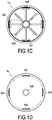
- the inner surface 1f of said floor 1c on the side intended to be in contact with said block of explosive material comprises 8 projecting embossments 1c3 arranged symmetrically radially in a star around the central opening 1c2 of the floor over a length less than the radius between the orifice 1c2 and the circumference of the floor, on which the surface 3d of said block of explosive material rest so as to allow the passage of air and / or water between said block of explosive material and the floor.
- Said floor 1c comprises perforations in the form of slots 1c1 forming said vents.
- the 4 slots 1c1 forming said vents are disposed at the periphery or circumference of said floor in the form of a circular arc at the foot at the junction with said cylindrical outer wall 1a) of the receptacle.
- the steps of placing the compressed blocks 3 in the containers 1 are done using a robot. Pliers position the compressed blocks 3 vertically containers, then they will be put in place by gravity.
- the flared shape ensures easy introduction by free fall into the container with a clearance between the side walls of the inner compartment 1d1 and those 3a of the block 3. This game generates a significant volume of air that is discharged through the vents 1c1.
- the apparent density of the cartridge in the water is thus from 1.35 to 1.40.
- the two flared openings 3b2 of the two detonation housings 3b are found opposite each other just below the two detonator introduction ports 2a and the second opening 3c2 of the central through-hole 3c is located opposite of the central orifice 2b of said lid.
- the circular transverse bottom wall 2c of the cover 2 surmounted by a tubular peripheral side wall 2d comprises on its external face first assembly members 2d1 in the form of embossing in the form of a flange 2d1, able to cooperate by force insertion, with elements complementary complementary embossing assembly 1e1 on the inner face of the longitudinal end of the outer cylindrical wall of the receptacle to allow the closure of the receptacle with the lid.
- Said cover 2 has on its external face second connecting elements in the form of embossing projecting from the lid 2d2, able to cooperate in force insertion, with complementary second complementary embossing assembly elements 1e2, on the inner face of the opposite longitudinal end of the outer cylindrical wall 1a of the receptacle below said floor so as to enable assembly, by force insertion, of said second connecting elements 2d2 of the cover of a first cartridge 10a arranged end to end axially with respect to a second cartridge 10b, with said second complementary assembly elements 1e2 of a second cartridge 10b as shown Figure 6A .
- the electric detonator 4 is replaced by a detonating cord 5, consisting of an explosive core such as pentrite contained in a textile sheath coated with a plastic envelope.
- the cartridge contains only one detonating cord.
- said cover 2 has a circular transverse bottom wall 2c comprising said introduction ports 2a partially closed by funnel-shaped caps on the underside of said bottom wall 2c.
- Each funnel-shaped cap is pierced and split in a cross by 4 slots 2a2 delimiting 4 elastic deformable elements 2a1 able to allow the introduction of said detonator or detonating cord 5 by passing through said introducer port 2a towards said housing detonation 3b and preventing the exit in the opposite direction of said detonator or detonating cord through said insertion port 2a once it is in place in said detonation housing 3b due to the partial closure of the orifice around the detonator wire 4a or the pressure exerted if necessary against the cord by said elastic elements following their deformation.
- a peripheral edge 2b1 in elevation around the central orifice 2b with respect to the bottom wall 2c of the cover comprises two diametrically opposite recesses 2b2 each capable of allowing a detonator wire 4a or detonating cord 5 to pass between the central orifice 2b and a detonator introduction port 2a for protecting the detonator wires or the detonating cord from friction or abrasion between the cover and the ground at the bottom of the hole.
- the detonator is an electric detonator comprising a tube 4 containing an explosive activated by an electrical pulse transmitted by the wire 4a which can explode the charge of the tube 4 which allows to produce a shock wave powerful enough to cause for sure the detonation of the explosive charge of the block of explosive material 3.
- the detonating cord 5 or the detonator 4, followed by its wire 4 is firstly introduced through the central opening 1c2 of the floor in a said longitudinal central cylindrical channel 1d of the receptacle, then it is taken out at 1c4 by the central orifice 2b of the lid, and finally it is introduced into a detonation chamber 3b by the detonation orifice of the cover 2a, the cord 5 or wire 4a extending in the said central channel of the inner compartment of the receptacle and then passing through a recess 2b2 of the peripheral edge in elevation 2b1 of the central orifice 2b of the cover to protect the detonator wire or detonating cord.
- the central channel 1d makes it possible to retract the wire 4a from the detonator from top to bottom before positioning the detonator in its housing 3b.
- the cartridge 10a, 10b is found hung in a balanced manner and can be lowered into the hole 11 by unwinding the wire 4a of the detonator without risk of deterioration of the wire 4a.
Landscapes
- Engineering & Computer Science (AREA)
- General Engineering & Computer Science (AREA)
- Portable Nailing Machines And Staplers (AREA)
- Air Bags (AREA)
- Braking Systems And Boosters (AREA)
Priority Applications (1)
| Application Number | Priority Date | Filing Date | Title |
|---|---|---|---|
| PL17167763T PL3239648T3 (pl) | 2016-04-27 | 2017-04-24 | Urządzenie detonatora pośredniego |
Applications Claiming Priority (1)
| Application Number | Priority Date | Filing Date | Title |
|---|---|---|---|
| FR1653739A FR3050816B1 (fr) | 2016-04-27 | 2016-04-27 | Dispositif renforcateur d'amorcage |
Publications (2)
| Publication Number | Publication Date |
|---|---|
| EP3239648A1 EP3239648A1 (fr) | 2017-11-01 |
| EP3239648B1 true EP3239648B1 (fr) | 2018-09-12 |
Family
ID=57184528
Family Applications (1)
| Application Number | Title | Priority Date | Filing Date |
|---|---|---|---|
| EP17167763.6A Active EP3239648B1 (fr) | 2016-04-27 | 2017-04-24 | Dispositif renforcateur d'amorcage |
Country Status (5)
| Country | Link |
|---|---|
| EP (1) | EP3239648B1 (pl) |
| ES (1) | ES2700800T3 (pl) |
| FR (1) | FR3050816B1 (pl) |
| PL (1) | PL3239648T3 (pl) |
| TR (1) | TR201819003T4 (pl) |
Cited By (7)
| Publication number | Priority date | Publication date | Assignee | Title |
|---|---|---|---|---|
| US11499401B2 (en) | 2021-02-04 | 2022-11-15 | DynaEnergetics Europe GmbH | Perforating gun assembly with performance optimized shaped charge load |
| US11661823B2 (en) | 2013-07-18 | 2023-05-30 | DynaEnergetics Europe GmbH | Perforating gun assembly and wellbore tool string with tandem seal adapter |
| US11753909B2 (en) | 2018-04-06 | 2023-09-12 | DynaEnergetics Europe GmbH | Perforating gun system and method of use |
| US11795791B2 (en) | 2021-02-04 | 2023-10-24 | DynaEnergetics Europe GmbH | Perforating gun assembly with performance optimized shaped charge load |
| USD1010758S1 (en) | 2019-02-11 | 2024-01-09 | DynaEnergetics Europe GmbH | Gun body |
| US12253339B2 (en) | 2021-10-25 | 2025-03-18 | DynaEnergetics Europe GmbH | Adapter and shaped charge apparatus for optimized perforation jet |
| US12366142B2 (en) | 2021-03-03 | 2025-07-22 | DynaEnergetics Europe GmbH | Modular perforating gun system |
Families Citing this family (2)
| Publication number | Priority date | Publication date | Assignee | Title |
|---|---|---|---|---|
| CN108981484A (zh) * | 2018-10-10 | 2018-12-11 | 六盘水久翔爆破工程有限责任公司 | 一种露天爆破的手持导爆管 |
| CN109405658A (zh) * | 2018-11-26 | 2019-03-01 | 山西江阳兴安民爆器材有限公司 | 一种结构安全起爆具及其组装工艺 |
Family Cites Families (7)
| Publication number | Priority date | Publication date | Assignee | Title |
|---|---|---|---|---|
| US3183836A (en) | 1963-08-21 | 1965-05-18 | Trojan Powder Co | Canister for cast primer |
| US3407730A (en) * | 1966-09-21 | 1968-10-29 | Trojan Powder Co | Retainer for holding a detonator in a detonator receptacle and explosive cartridge container containing the same |
| US4334476A (en) | 1980-07-02 | 1982-06-15 | Mining Services International Corporation | Primer cup |
| US4485741A (en) | 1983-04-13 | 1984-12-04 | Apache Powder Company | Booster container with isolated and open cord tunnels |
| SE456528B (sv) * | 1986-02-17 | 1988-10-10 | Nobel Kemi Ab | Tendare |
| US5780764A (en) * | 1996-01-11 | 1998-07-14 | The Ensign-Bickford Company | Booster explosive devices and combinations thereof with explosive accessory charges |
| EP2177866A1 (en) | 2008-10-20 | 2010-04-21 | S.E.I. Societa Esplosivi Industriali S.p.A. | Booster device for explosives and relative explosive device |
-
2016
- 2016-04-27 FR FR1653739A patent/FR3050816B1/fr not_active Expired - Fee Related
-
2017
- 2017-04-24 PL PL17167763T patent/PL3239648T3/pl unknown
- 2017-04-24 EP EP17167763.6A patent/EP3239648B1/fr active Active
- 2017-04-24 TR TR2018/19003T patent/TR201819003T4/tr unknown
- 2017-04-24 ES ES17167763T patent/ES2700800T3/es active Active
Cited By (9)
| Publication number | Priority date | Publication date | Assignee | Title |
|---|---|---|---|---|
| US11661823B2 (en) | 2013-07-18 | 2023-05-30 | DynaEnergetics Europe GmbH | Perforating gun assembly and wellbore tool string with tandem seal adapter |
| US12078038B2 (en) | 2013-07-18 | 2024-09-03 | DynaEnergetics Europe GmbH | Perforating gun orientation system |
| US11753909B2 (en) | 2018-04-06 | 2023-09-12 | DynaEnergetics Europe GmbH | Perforating gun system and method of use |
| USD1010758S1 (en) | 2019-02-11 | 2024-01-09 | DynaEnergetics Europe GmbH | Gun body |
| US11499401B2 (en) | 2021-02-04 | 2022-11-15 | DynaEnergetics Europe GmbH | Perforating gun assembly with performance optimized shaped charge load |
| US11795791B2 (en) | 2021-02-04 | 2023-10-24 | DynaEnergetics Europe GmbH | Perforating gun assembly with performance optimized shaped charge load |
| US12338716B2 (en) | 2021-02-04 | 2025-06-24 | DynaEnergetics Europe GmbH | Perforating gun assembly with performance optimized shaped charge load |
| US12366142B2 (en) | 2021-03-03 | 2025-07-22 | DynaEnergetics Europe GmbH | Modular perforating gun system |
| US12253339B2 (en) | 2021-10-25 | 2025-03-18 | DynaEnergetics Europe GmbH | Adapter and shaped charge apparatus for optimized perforation jet |
Also Published As
| Publication number | Publication date |
|---|---|
| EP3239648A1 (fr) | 2017-11-01 |
| FR3050816A1 (fr) | 2017-11-03 |
| PL3239648T3 (pl) | 2019-02-28 |
| FR3050816B1 (fr) | 2019-05-31 |
| TR201819003T4 (tr) | 2019-01-21 |
| ES2700800T3 (es) | 2019-02-19 |
Similar Documents
| Publication | Publication Date | Title |
|---|---|---|
| EP3239648B1 (fr) | Dispositif renforcateur d'amorcage | |
| RU2489672C2 (ru) | Дробильный патрон с пороховым зарядом для горных пород | |
| AU2001235240B8 (en) | Cartridge shell and cartridge for blast holes and method of use | |
| US4920885A (en) | Explosive charge containing magazine for RAM setting gun | |
| FR2649478A1 (fr) | Generateur pyrotechnique de gaz froids et son procede de fabrication | |
| KR101476957B1 (ko) | 탄체 제조 방법 | |
| EP1181498B1 (fr) | Tube allumeur pour une munition d'artillerie | |
| WO2001057466A1 (fr) | Module d'allumage de detonateur pour charge explosive, procede et outillage de fabrication d'un detonateur equipe d'un tel module | |
| US20110259229A1 (en) | Pyrotechnic device | |
| MX2008012121A (es) | Detonacion de explosivos. | |
| US20150053106A1 (en) | Blasting cartridge | |
| US431601A (en) | Wilhelm lorenz | |
| EP3228972B1 (fr) | Ensemble de deux reservoirs prêts a être assembles par vissage pour former une cartouche d'explosif bi-composant | |
| FR2836461A1 (fr) | Dispositif de dispersion pyrotechnique d'un fluide | |
| EP0045226B1 (fr) | Bouchon allumeur initiable par frottement ou par gaz chauds | |
| FR2459558A3 (fr) | Bouchons de securite pour elements de batteries d'accumulateurs | |
| FR2846698A1 (fr) | Dispositif pyrotechnique a piston pour la dispersion d'un fluide liquide destine a la denaturation de valeurs | |
| FR2684752A1 (fr) | Relais d'amorcage par cordeau detonant. | |
| FR2754052A1 (fr) | Projectile d'exercice balistique | |
| US987590A (en) | Shell or projectile. | |
| FR2543658A1 (fr) | Procede et dispositif de vidange mettant en oeuvre des moyens pyrotechniques | |
| FR2633712A1 (fr) | Perfectionnement apporte aux munitions a etuis rechargeables | |
| EP1582321A1 (fr) | Dispositif de découpe d'une structure dans un véhicule automobile | |
| FR2846699A1 (fr) | Dispositif pyrotechnique de dispersion d'un fluide liquide destine a la denaturation de valeurs, utilisant une piece a profil contondant | |
| FR2520862A1 (fr) | Mine anti-personnel a effet dirige |
Legal Events
| Date | Code | Title | Description |
|---|---|---|---|
| PUAI | Public reference made under article 153(3) epc to a published international application that has entered the european phase |
Free format text: ORIGINAL CODE: 0009012 |
|
| STAA | Information on the status of an ep patent application or granted ep patent |
Free format text: STATUS: THE APPLICATION HAS BEEN PUBLISHED |
|
| AK | Designated contracting states |
Kind code of ref document: A1 Designated state(s): AL AT BE BG CH CY CZ DE DK EE ES FI FR GB GR HR HU IE IS IT LI LT LU LV MC MK MT NL NO PL PT RO RS SE SI SK SM TR |
|
| AX | Request for extension of the european patent |
Extension state: BA ME |
|
| STAA | Information on the status of an ep patent application or granted ep patent |
Free format text: STATUS: REQUEST FOR EXAMINATION WAS MADE |
|
| 17P | Request for examination filed |
Effective date: 20171130 |
|
| RAV | Requested validation state of the european patent: fee paid |
Extension state: MA Effective date: 20171130 |
|
| RBV | Designated contracting states (corrected) |
Designated state(s): AL AT BE BG CH CY CZ DE DK EE ES FI FR GB GR HR HU IE IS IT LI LT LU LV MC MK MT NL NO PL PT RO RS SE SI SK SM TR |
|
| GRAP | Despatch of communication of intention to grant a patent |
Free format text: ORIGINAL CODE: EPIDOSNIGR1 |
|
| STAA | Information on the status of an ep patent application or granted ep patent |
Free format text: STATUS: GRANT OF PATENT IS INTENDED |
|
| INTG | Intention to grant announced |
Effective date: 20180426 |
|
| RIC1 | Information provided on ipc code assigned before grant |
Ipc: F42B 3/26 20060101ALI20180417BHEP Ipc: F42D 1/04 20060101ALN20180417BHEP Ipc: F42B 3/02 20060101AFI20180417BHEP |
|
| GRAS | Grant fee paid |
Free format text: ORIGINAL CODE: EPIDOSNIGR3 |
|
| GRAA | (expected) grant |
Free format text: ORIGINAL CODE: 0009210 |
|
| STAA | Information on the status of an ep patent application or granted ep patent |
Free format text: STATUS: THE PATENT HAS BEEN GRANTED |
|
| AK | Designated contracting states |
Kind code of ref document: B1 Designated state(s): AL AT BE BG CH CY CZ DE DK EE ES FI FR GB GR HR HU IE IS IT LI LT LU LV MC MK MT NL NO PL PT RO RS SE SI SK SM TR |
|
| REG | Reference to a national code |
Ref country code: GB Ref legal event code: FG4D Free format text: NOT ENGLISH |
|
| REG | Reference to a national code |
Ref country code: CH Ref legal event code: EP |
|
| REG | Reference to a national code |
Ref country code: IE Ref legal event code: FG4D Free format text: LANGUAGE OF EP DOCUMENT: FRENCH |
|
| REG | Reference to a national code |
Ref country code: DE Ref legal event code: R096 Ref document number: 602017000390 Country of ref document: DE |
|
| REG | Reference to a national code |
Ref country code: AT Ref legal event code: REF Ref document number: 1041126 Country of ref document: AT Kind code of ref document: T Effective date: 20181015 |
|
| REG | Reference to a national code |
Ref country code: CH Ref legal event code: NV Representative=s name: BOVARD AG PATENT- UND MARKENANWAELTE, CH |
|
| REG | Reference to a national code |
Ref country code: NL Ref legal event code: MP Effective date: 20180912 |
|
| REG | Reference to a national code |
Ref country code: LT Ref legal event code: MG4D |
|
| REG | Reference to a national code |
Ref country code: SE Ref legal event code: TRGR |
|
| PG25 | Lapsed in a contracting state [announced via postgrant information from national office to epo] |
Ref country code: BG Free format text: LAPSE BECAUSE OF FAILURE TO SUBMIT A TRANSLATION OF THE DESCRIPTION OR TO PAY THE FEE WITHIN THE PRESCRIBED TIME-LIMIT Effective date: 20181212 Ref country code: LT Free format text: LAPSE BECAUSE OF FAILURE TO SUBMIT A TRANSLATION OF THE DESCRIPTION OR TO PAY THE FEE WITHIN THE PRESCRIBED TIME-LIMIT Effective date: 20180912 Ref country code: FI Free format text: LAPSE BECAUSE OF FAILURE TO SUBMIT A TRANSLATION OF THE DESCRIPTION OR TO PAY THE FEE WITHIN THE PRESCRIBED TIME-LIMIT Effective date: 20180912 Ref country code: RS Free format text: LAPSE BECAUSE OF FAILURE TO SUBMIT A TRANSLATION OF THE DESCRIPTION OR TO PAY THE FEE WITHIN THE PRESCRIBED TIME-LIMIT Effective date: 20180912 |
|
| REG | Reference to a national code |
Ref country code: NO Ref legal event code: T2 Effective date: 20180912 |
|
| REG | Reference to a national code |
Ref country code: ES Ref legal event code: FG2A Ref document number: 2700800 Country of ref document: ES Kind code of ref document: T3 Effective date: 20190219 |
|
| PG25 | Lapsed in a contracting state [announced via postgrant information from national office to epo] |
Ref country code: AL Free format text: LAPSE BECAUSE OF FAILURE TO SUBMIT A TRANSLATION OF THE DESCRIPTION OR TO PAY THE FEE WITHIN THE PRESCRIBED TIME-LIMIT Effective date: 20180912 Ref country code: LV Free format text: LAPSE BECAUSE OF FAILURE TO SUBMIT A TRANSLATION OF THE DESCRIPTION OR TO PAY THE FEE WITHIN THE PRESCRIBED TIME-LIMIT Effective date: 20180912 Ref country code: HR Free format text: LAPSE BECAUSE OF FAILURE TO SUBMIT A TRANSLATION OF THE DESCRIPTION OR TO PAY THE FEE WITHIN THE PRESCRIBED TIME-LIMIT Effective date: 20180912 |
|
| REG | Reference to a national code |
Ref country code: AT Ref legal event code: MK05 Ref document number: 1041126 Country of ref document: AT Kind code of ref document: T Effective date: 20180912 |
|
| PG25 | Lapsed in a contracting state [announced via postgrant information from national office to epo] |
Ref country code: EE Free format text: LAPSE BECAUSE OF FAILURE TO SUBMIT A TRANSLATION OF THE DESCRIPTION OR TO PAY THE FEE WITHIN THE PRESCRIBED TIME-LIMIT Effective date: 20180912 Ref country code: RO Free format text: LAPSE BECAUSE OF FAILURE TO SUBMIT A TRANSLATION OF THE DESCRIPTION OR TO PAY THE FEE WITHIN THE PRESCRIBED TIME-LIMIT Effective date: 20180912 Ref country code: IS Free format text: LAPSE BECAUSE OF FAILURE TO SUBMIT A TRANSLATION OF THE DESCRIPTION OR TO PAY THE FEE WITHIN THE PRESCRIBED TIME-LIMIT Effective date: 20190112 Ref country code: NL Free format text: LAPSE BECAUSE OF FAILURE TO SUBMIT A TRANSLATION OF THE DESCRIPTION OR TO PAY THE FEE WITHIN THE PRESCRIBED TIME-LIMIT Effective date: 20180912 Ref country code: AT Free format text: LAPSE BECAUSE OF FAILURE TO SUBMIT A TRANSLATION OF THE DESCRIPTION OR TO PAY THE FEE WITHIN THE PRESCRIBED TIME-LIMIT Effective date: 20180912 |
|
| PG25 | Lapsed in a contracting state [announced via postgrant information from national office to epo] |
Ref country code: SK Free format text: LAPSE BECAUSE OF FAILURE TO SUBMIT A TRANSLATION OF THE DESCRIPTION OR TO PAY THE FEE WITHIN THE PRESCRIBED TIME-LIMIT Effective date: 20180912 Ref country code: SM Free format text: LAPSE BECAUSE OF FAILURE TO SUBMIT A TRANSLATION OF THE DESCRIPTION OR TO PAY THE FEE WITHIN THE PRESCRIBED TIME-LIMIT Effective date: 20180912 Ref country code: PT Free format text: LAPSE BECAUSE OF FAILURE TO SUBMIT A TRANSLATION OF THE DESCRIPTION OR TO PAY THE FEE WITHIN THE PRESCRIBED TIME-LIMIT Effective date: 20190112 |
|
| REG | Reference to a national code |
Ref country code: DE Ref legal event code: R097 Ref document number: 602017000390 Country of ref document: DE |
|
| PLBE | No opposition filed within time limit |
Free format text: ORIGINAL CODE: 0009261 |
|
| STAA | Information on the status of an ep patent application or granted ep patent |
Free format text: STATUS: NO OPPOSITION FILED WITHIN TIME LIMIT |
|
| PG25 | Lapsed in a contracting state [announced via postgrant information from national office to epo] |
Ref country code: DK Free format text: LAPSE BECAUSE OF FAILURE TO SUBMIT A TRANSLATION OF THE DESCRIPTION OR TO PAY THE FEE WITHIN THE PRESCRIBED TIME-LIMIT Effective date: 20180912 |
|
| 26N | No opposition filed |
Effective date: 20190613 |
|
| PG25 | Lapsed in a contracting state [announced via postgrant information from national office to epo] |
Ref country code: SI Free format text: LAPSE BECAUSE OF FAILURE TO SUBMIT A TRANSLATION OF THE DESCRIPTION OR TO PAY THE FEE WITHIN THE PRESCRIBED TIME-LIMIT Effective date: 20180912 |
|
| PG25 | Lapsed in a contracting state [announced via postgrant information from national office to epo] |
Ref country code: MC Free format text: LAPSE BECAUSE OF FAILURE TO SUBMIT A TRANSLATION OF THE DESCRIPTION OR TO PAY THE FEE WITHIN THE PRESCRIBED TIME-LIMIT Effective date: 20180912 |
|
| VS25 | Lapsed in a validation state [announced via postgrant information from nat. office to epo] |
Ref country code: MA Free format text: LAPSE BECAUSE OF FAILURE TO SUBMIT A TRANSLATION OF THE DESCRIPTION OR TO PAY THE FEE WITHIN THE PRESCRIBED TIME-LIMIT Effective date: 20180912 |
|
| REG | Reference to a national code |
Ref country code: CH Ref legal event code: PCOW Free format text: NEW ADDRESS: 1 TERASSE BELLINI TOUR INITIALE, 92935 PARIS LA DEFENSE (FR) |
|
| REG | Reference to a national code |
Ref country code: NO Ref legal event code: CHAD Owner name: NITRATES & INNOVATION, FR |
|
| REG | Reference to a national code |
Ref country code: LU Ref legal event code: HC Owner name: NITRATES & INNOVATION; FR Free format text: FORMER OWNER: NITRATES&INNOVATION Effective date: 20210216 |
|
| PG25 | Lapsed in a contracting state [announced via postgrant information from national office to epo] |
Ref country code: CY Free format text: LAPSE BECAUSE OF FAILURE TO SUBMIT A TRANSLATION OF THE DESCRIPTION OR TO PAY THE FEE WITHIN THE PRESCRIBED TIME-LIMIT Effective date: 20180912 |
|
| PG25 | Lapsed in a contracting state [announced via postgrant information from national office to epo] |
Ref country code: GR Free format text: LAPSE BECAUSE OF FAILURE TO SUBMIT A TRANSLATION OF THE DESCRIPTION OR TO PAY THE FEE WITHIN THE PRESCRIBED TIME-LIMIT Effective date: 20180912 |
|
| PG25 | Lapsed in a contracting state [announced via postgrant information from national office to epo] |
Ref country code: HU Free format text: LAPSE BECAUSE OF FAILURE TO SUBMIT A TRANSLATION OF THE DESCRIPTION OR TO PAY THE FEE WITHIN THE PRESCRIBED TIME-LIMIT; INVALID AB INITIO Effective date: 20170424 Ref country code: MT Free format text: LAPSE BECAUSE OF FAILURE TO SUBMIT A TRANSLATION OF THE DESCRIPTION OR TO PAY THE FEE WITHIN THE PRESCRIBED TIME-LIMIT Effective date: 20180912 |
|
| REG | Reference to a national code |
Ref country code: BE Ref legal event code: PD Owner name: NITRATES & INNOVATION; FR Free format text: DETAILS ASSIGNMENT: CHANGE OF OWNER(S), OTHER; FORMER OWNER NAME: NITRATES&INNOVATION Effective date: 20210315 |
|
| PG25 | Lapsed in a contracting state [announced via postgrant information from national office to epo] |
Ref country code: MK Free format text: LAPSE BECAUSE OF FAILURE TO SUBMIT A TRANSLATION OF THE DESCRIPTION OR TO PAY THE FEE WITHIN THE PRESCRIBED TIME-LIMIT Effective date: 20180912 |
|
| REG | Reference to a national code |
Ref country code: DE Ref legal event code: R082 Ref document number: 602017000390 Country of ref document: DE Representative=s name: CBDL PATENTANWAELTE GBR, DE Ref country code: DE Ref legal event code: R082 Ref document number: 602017000390 Country of ref document: DE Representative=s name: CBDL PATENTANWAELTE EGBR, DE |
|
| REG | Reference to a national code |
Ref country code: FR Ref legal event code: PLFP Year of fee payment: 7 |
|
| REG | Reference to a national code |
Ref country code: ES Ref legal event code: PC2A Owner name: INNOVATION & INDUSTRIE Effective date: 20230622 |
|
| REG | Reference to a national code |
Ref country code: NO Ref legal event code: CHAD Owner name: INNOVATION & INDUSTRIE, FR |
|
| REG | Reference to a national code |
Ref country code: LU Ref legal event code: HC Owner name: INNOVATION & INDUSTRIE; FR Free format text: FORMER OWNER: NITRATES & INNOVATION Effective date: 20230621 |
|
| REG | Reference to a national code |
Ref country code: DE Ref legal event code: R081 Ref document number: 602017000390 Country of ref document: DE Owner name: INNOVATION & INDUSTRIE, FR Free format text: FORMER OWNER: NITRATES&INNOVATION, PARIS, FR |
|
| REG | Reference to a national code |
Ref country code: BE Ref legal event code: HC Free format text: DETAILS ASSIGNMENT: CHANGE OF OWNER(S), CHANGE OF OWNER(S) NAME Effective date: 20230728 |
|
| REG | Reference to a national code |
Ref country code: BE Ref legal event code: HC Owner name: INNOVATION & INDUSTRIE; FR Free format text: DETAILS ASSIGNMENT: CHANGE OF OWNER(S), CHANGE OF OWNER(S) NAME; FORMER OWNER NAME: NITRATES & INNOVATION Effective date: 20231221 |
|
| PGFP | Annual fee paid to national office [announced via postgrant information from national office to epo] |
Ref country code: LU Payment date: 20250429 Year of fee payment: 9 |
|
| PGFP | Annual fee paid to national office [announced via postgrant information from national office to epo] |
Ref country code: PL Payment date: 20250404 Year of fee payment: 9 Ref country code: DE Payment date: 20250411 Year of fee payment: 9 |
|
| PGFP | Annual fee paid to national office [announced via postgrant information from national office to epo] |
Ref country code: GB Payment date: 20250417 Year of fee payment: 9 Ref country code: ES Payment date: 20250512 Year of fee payment: 9 |
|
| PGFP | Annual fee paid to national office [announced via postgrant information from national office to epo] |
Ref country code: NO Payment date: 20250425 Year of fee payment: 9 |
|
| PGFP | Annual fee paid to national office [announced via postgrant information from national office to epo] |
Ref country code: BE Payment date: 20250423 Year of fee payment: 9 Ref country code: IT Payment date: 20250409 Year of fee payment: 9 |
|
| PGFP | Annual fee paid to national office [announced via postgrant information from national office to epo] |
Ref country code: FR Payment date: 20250402 Year of fee payment: 9 |
|
| PGFP | Annual fee paid to national office [announced via postgrant information from national office to epo] |
Ref country code: CH Payment date: 20250501 Year of fee payment: 9 |
|
| PGFP | Annual fee paid to national office [announced via postgrant information from national office to epo] |
Ref country code: TR Payment date: 20250409 Year of fee payment: 9 |
|
| PGFP | Annual fee paid to national office [announced via postgrant information from national office to epo] |
Ref country code: CZ Payment date: 20250409 Year of fee payment: 9 |
|
| PGFP | Annual fee paid to national office [announced via postgrant information from national office to epo] |
Ref country code: IE Payment date: 20250422 Year of fee payment: 9 |
|
| PGFP | Annual fee paid to national office [announced via postgrant information from national office to epo] |
Ref country code: SE Payment date: 20250422 Year of fee payment: 9 |
|
| REG | Reference to a national code |
Ref country code: DE Ref legal event code: R082 Ref document number: 602017000390 Country of ref document: DE |