EP3239535A1 - Befestigungsvorrichtung und system - Google Patents
Befestigungsvorrichtung und system Download PDFInfo
- Publication number
- EP3239535A1 EP3239535A1 EP16167108.6A EP16167108A EP3239535A1 EP 3239535 A1 EP3239535 A1 EP 3239535A1 EP 16167108 A EP16167108 A EP 16167108A EP 3239535 A1 EP3239535 A1 EP 3239535A1
- Authority
- EP
- European Patent Office
- Prior art keywords
- article
- shaft
- attachment
- support
- support collar
- Prior art date
- Legal status (The legal status is an assumption and is not a legal conclusion. Google has not performed a legal analysis and makes no representation as to the accuracy of the status listed.)
- Withdrawn
Links
- 230000001447 compensatory effect Effects 0.000 description 3
Images
Classifications
-
- F—MECHANICAL ENGINEERING; LIGHTING; HEATING; WEAPONS; BLASTING
- F16—ENGINEERING ELEMENTS AND UNITS; GENERAL MEASURES FOR PRODUCING AND MAINTAINING EFFECTIVE FUNCTIONING OF MACHINES OR INSTALLATIONS; THERMAL INSULATION IN GENERAL
- F16B—DEVICES FOR FASTENING OR SECURING CONSTRUCTIONAL ELEMENTS OR MACHINE PARTS TOGETHER, e.g. NAILS, BOLTS, CIRCLIPS, CLAMPS, CLIPS OR WEDGES; JOINTS OR JOINTING
- F16B35/00—Screw-bolts; Stay-bolts; Screw-threaded studs; Screws; Set screws
- F16B35/04—Screw-bolts; Stay-bolts; Screw-threaded studs; Screws; Set screws with specially-shaped head or shaft in order to fix the bolt on or in an object
- F16B35/041—Specially-shaped shafts
- F16B35/048—Specially-shaped necks
-
- F—MECHANICAL ENGINEERING; LIGHTING; HEATING; WEAPONS; BLASTING
- F16—ENGINEERING ELEMENTS AND UNITS; GENERAL MEASURES FOR PRODUCING AND MAINTAINING EFFECTIVE FUNCTIONING OF MACHINES OR INSTALLATIONS; THERMAL INSULATION IN GENERAL
- F16B—DEVICES FOR FASTENING OR SECURING CONSTRUCTIONAL ELEMENTS OR MACHINE PARTS TOGETHER, e.g. NAILS, BOLTS, CIRCLIPS, CLAMPS, CLIPS OR WEDGES; JOINTS OR JOINTING
- F16B5/00—Joining sheets or plates, e.g. panels, to one another or to strips or bars parallel to them
- F16B5/02—Joining sheets or plates, e.g. panels, to one another or to strips or bars parallel to them by means of fastening members using screw-thread
- F16B5/0241—Joining sheets or plates, e.g. panels, to one another or to strips or bars parallel to them by means of fastening members using screw-thread with the possibility for the connection to absorb deformation, e.g. thermal or vibrational
Definitions
- the invention relates to a fastening device and a system having a first article, a second article and a fastening device.
- Devices for fastening a first object to a second object, which have a head and a shaft protruding from the head in a fastening direction, wherein the head has a bearing surface facing the mounting direction for a support on the first object, which in the Mounting direction is surmounted only by the shaft. It is also known that the shaft has a contact surface pointing in the direction of attachment for engagement with the second object.
- the first object makes compensatory movements, it may happen that the first object hits the shaft. Due to the forces or torques occurring in this case, the connection between the device and the second object or the device itself may be damaged.
- the object of the invention is to provide a device and a system with which a robust attachment of a first object to a second object is possible.
- the object is achieved in that the shaft has a support collar projecting beyond the rest of the shaft transversely to the fastening direction, which has a smaller distance in the fastening direction to the contact surface than to the contact surface. Characterized in that the support collar projects beyond the rest of the shaft transversely to the fastening direction, it is ensured that the first object abuts in the case of compensating movements transversely to the fastening direction of the support collar and is supported against further movement on the shaft. The fact that the support collar and in particular its abutment point of the first object in the attachment direction to the contact surface has a smaller distance than the support surface, it is ensured that the forces or torques occurring are relatively small. Thus, a robust attachment of the first article to the second article is achieved.
- the direction indication "transversely to the fastening direction” in the sense of the invention designates any direction inclined to the fastening direction, in particular at right angles.
- a preferred embodiment is characterized in that the support surface projects beyond the support collar transversely to the fastening direction. As a result, pinching of the first object between the support surface and the second object is possible.
- a preferred embodiment is characterized in that the shank comprises a fastening part for direct attachment to the second article and a separate attachment from the fastening part for direct attachment to the fastening part.
- the fastening part on the support collar.
- the attachment on the support collar is characterized in that the shank comprises a fastening part for direct attachment to the second article and a separate attachment from the fastening part for direct attachment to the fastening part.
- a preferred embodiment is characterized in that the support collar has the contact surface. As a result, a further reduction of the occurring forces or torques is achieved.
- a preferred embodiment is characterized in that the shaft comprises a core part and a ring part enclosing the core part, wherein the ring part has the support collar.
- a preferred embodiment is characterized in that the support collar has an annular circumference transversely to the fastening direction.
- the object is also achieved by a system comprising a first article, a second article and a device, wherein the first article is fastened by means of the device in a fastening direction to the second article, wherein the device comprises a head and one of the head in the Mounting direction protruding shaft, wherein the head has a bearing in the direction of attachment bearing surface which rests on the first object, wherein between the shaft, the support surface, the first object and the second object, a space for compensating movements of the first article is formed transversely to the mounting direction , characterized in that the shaft has a space transverse to the mounting direction limiting support collar, which has a smaller distance in the mounting direction to the contact surface than the support surface.
- a preferred embodiment is characterized in that the first article is a grate.
- a preferred embodiment is characterized in that the support collar has a width a as the largest dimension transverse to the attachment direction and the grid has two mutually parallel grid bars with a distance b to each other, between which the device is arranged, and wherein the width a smaller than the distance b is.
- the width a is at most 0.8 times the distance b.
- the width a is at least half as large as the distance b.
- a preferred embodiment is characterized in that the first object is clamped directly between the support surface and the second object.
- a preferred embodiment is characterized in that the first object is clamped directly between the support surface and the support collar. As a result, the force exerted by the bearing surface on the first object, transferred to the support collar, which additionally reduces the forces or torques occurring.
- a system 100 that includes a first article 101, a second article 102, and a device 120 by which the first article 101 is attached to the second article 102 in a mounting direction 110.
- the device 120 has a head 130 and a shaft 140 protruding from the head 130 in the fastening direction 110.
- the shaft 140 has an abutment surface 180, which rests against the second object 102 in the attachment direction 110.
- the head 130 has a head bottom or bearing surface 150, which points in the fastening direction 110 and rests on the first object 101 and has a spacing h 1 in the fastening direction 110 relative to the contact surface 180.
- a space 160 for compensating movements of the first object 101 transversely to the fastening direction 110 is formed between the shaft 140, the bearing surface 150, the first object 101 and the second object 102.
- the shaft 140 has a support collar 170 which projects beyond the remaining shaft 140 transversely to the fastening direction 110, that is to say encompasses the widest point of the shaft 140.
- the support collar 170 bounds the space 160 transversely to the attachment direction 110, so that the first article 101 in the Trap of compensatory movements against the device 120 to the support collar 170 and not to the remaining shaft 140 abuts.
- the support collar 170 has a distance h 2 in the attachment direction 110 to the contact surface 150 and a distance h 1 -h 2 to the contact surface 150, where h 2 ⁇ h 1 -h 2 .
- the first object 101 abuts the shaft 140 in the vicinity of the contact surface 180, so that the forces or torques occurring in this case are relatively small.
- the first article 101 comprises a grid, of which two grid bars parallel to one another are shown at a distance b from one another, between which the device 120 is arranged.
- the support collar 170 has, as the largest dimension transverse to the attachment direction 110, a width a which is 0.7 times the distance b.
- the support surface 150 projects beyond the support collar 170 transversely to the attachment direction 110.
- the first object 101 is clamped directly between the support surface 150 and the second object 102.
- a compensation movement of the first object 101 relative to the device 120 therefore initially counteracts a relatively small force, namely the frictional force due to the clamping.
- the compensation movement counteracts a relatively large force, without the device 120 or its connection to the second object 102 being damaged.
- the shank 140 comprises a fastening part 141 for direct attachment to the second object, such as a nail, a screw, a dowel or a threaded bolt, and an attachment 142 separate from the fastening part 141 for direct attachment to the fastening part 141, for example Screw.
- the attachment 142 has the support collar 170.
- the shaft 140 comprises a core part 143 and a ring part 144 enclosing the core part 143, the ring part 144 having the support collar 170.
- the ring member 144 is, for example, plugged or pressed onto the core part 143.
- the support collar 170 has an annular circumference transverse to the attachment direction 110.
- a system 200 is illustrated that includes a first article 201, a second article 202, and a device 220 by which the first article 201 is attached to the second article 202 in a direction of attachment 210.
- the device 220 has a head 230 and a head 230 in the Mounting direction 210 projecting shaft 240 on.
- the shaft 240 has an abutment surface 280, which rests against the second object 202 in the attachment direction 210.
- the head 230 has a head bottom or bearing surface 250 which points in the fastening direction 210 and rests on the first object 201 and has a spacing h 1 in the fastening direction 210 relative to the contact surface 280.
- a space 260 for compensating movements of the first article 201 transversely to the attachment direction 210 is formed.
- the shank 240 has a support collar 270 which projects beyond the remaining shank 240 transversely to the attachment direction 210, that is to say encompasses the widest point of the shank 240.
- the support collar 270 bounds the space 260 transversely to the attachment direction 210, so that the first object 201 abuts the support collar 270 and not the remaining shaft 240 in the event of compensatory movements with respect to the device 220.
- the support collar 270 has in the attachment direction 210 to the contact surface 250 a distance h 2 and the support surface 250 a distance h 1 -h 2 , wherein h 2 ⁇ h 1 -h 2 .
- the first object 201 abuts against the shaft 240 in the vicinity of the contact surface 280, so that the forces or torques occurring in this case are relatively small.
- the first article 201 comprises a grid, of which two grid bars parallel to one another are shown at a distance b from one another, between which the device 220 is arranged.
- the support collar 270 has, across the attachment direction 210, a width a which is 0.7 times the distance b.
- the support collar 270 has a flange 271 and on the flange 271, the contact surface 280.
- the first article 201 is clamped directly between the support surface 250 and the support collar 270, in this case the flange 271.
- a compensation movement of the first object 201 relative to the device 220 therefore initially counteracts a relatively small force, namely the frictional force due to the clamping.
- the compensating movement counteracts a relatively large force, without damaging the device 220 or its connection to the second object 202.
- the shank 240 comprises a fastening part 241 for direct attachment to the second object, such as a nail, a screw, a dowel or a threaded bolt, and a separate from the mounting part 241 attachment 242 for direct attachment to the fastening part 241, for example by screwing.
- the fastening part 241 on the support collar 270 has an annular circumference transverse to the attachment direction 210.
- the invention has been described by means of examples of a device for fastening a first article to a second article.
- the features of the described embodiments can also be combined with each other as desired within a single fastening device.
- the device according to the invention and the method according to the invention are also suitable for other purposes.
Landscapes
- Engineering & Computer Science (AREA)
- General Engineering & Computer Science (AREA)
- Mechanical Engineering (AREA)
- Connection Of Plates (AREA)
- Supports Or Holders For Household Use (AREA)
Abstract
Vorrichtung 220 und System zur Befestigung eines ersten Gegenstandes 201 an einem zweiten Gegenstand 202, mit einem Kopf 230 und einem von dem Kopf in einer Befestigungsrichtung 210 abragenden Schaft 240 für eine unmittelbare Befestigung an dem zweiten Gegenstand, wobei der Kopf eine in die Befestigungsrichtung weisende Auflagefläche 250 für eine Auflage auf dem ersten Gegenstand aufweist, welche in der Befestigungsrichtung nur von dem Schaft überragt wird, wobei der Schaft eine in die Befestigungsrichtung weisende Anlagefläche 280 für eine Anlage an dem zweiten Gegenstand aufweist, wobei der Schaft einen den übrigen Schaft quer zur Befestigungsrichtung überragenden Stützbund 270 aufweist, welcher in der Befestigungsrichtung zur Anlagefläche einen kleineren Abstand aufweist als zur Auflagefläche.
Description
- Die Erfindung betrifft eine Befestigungsvorrichtung sowie ein System mit einem ersten Gegenstand, einem zweiten Gegenstand und einer Befestigungsvorrichtung.
- Es sind Vorrichtungen zur Befestigung eines ersten Gegenstandes an einem zweiten Gegenstand bekannt, welche einen Kopf und einen von dem Kopf in einer Befestigungsrichtung abragenden Schaft aufweisen, wobei der Kopf eine in die Befestigungsrichtung weisende Auflagefläche für eine Auflage auf dem ersten Gegenstand aufweist, welche in der Befestigungsrichtung nur von dem Schaft überragt wird. Bekannt ist auch, dass der Schaft eine in die Befestigungsrichtung weisende Anlagefläche für eine Anlage an dem zweiten Gegenstand aufweist.
- In dem Fall, dass der erste Gegenstand Ausgleichsbewegungen macht, kann es vorkommen, dass der erste Gegenstand an den Schaft stösst. Durch die dabei auftretenden Kräfte oder Drehmomente wird unter Umständen die Verbindung zwischen der Vorrichtung und dem zweiten Gegenstand oder die Vorrichtung selbst beschädigt.
- Aufgabe der Erfindung ist es, eine Vorrichtung und ein System zur Verfügung zu stellen, mit denen eine robuste Befestigung eines ersten Gegenstands an einem zweiten Gegenstand möglich ist.
- Die Aufgabe wird dadurch gelöst, dass der Schaft einen den übrigen Schaft quer zur Befestigungsrichtung überragenden Stützbund aufweist, welcher in der Befestigungsrichtung zur Anlagefläche einen kleineren Abstand aufweist als zur Auflagefläche. Dadurch, dass der Stützbund den übrigen Schaft quer zur Befestigungsrichtung überragt, ist gewährleistet, dass der erste Gegenstand im Falle von Ausgleichsbewegungen quer zur Befestigungsrichtung an dem Stützbund anstösst und gegen eine weitere Bewegung auf den Schaft zu abgestützt wird. Dadurch, dass der Stützbund und insbesondere dessen Anstossstelle des ersten Gegenstands in der Befestigungsrichtung zur Anlagefläche einen kleineren Abstand aufweist als zur Auflagefläche, ist gewährleistet, dass die auftretenden Kräfte oder Drehmomente relativ gering sind. Somit wird eine robuste Befestigung des ersten Gegenstands an dem zweiten Gegenstand erreicht.
- Die Richtungsangabe "quer zur Befestigungsrichtung" bezeichnet im Sinne der Erfindung eine beliebige zur Befestigungsrichtung geneigte, insbesondere rechtwinklig geneigte Richtung.
- Eine bevorzugte Ausführungsform ist dadurch gekennzeichnet, dass die Auflagefläche den Stützbund quer zur Befestigungsrichtung überragt. Dadurch ist ein Einklemmen des ersten Gegenstands zwischen der Auflagefläche und dem zweiten Gegenstand möglich.
- Eine bevorzugte Ausführungsform ist dadurch gekennzeichnet, dass der Schaft ein Befestigungsteil für eine unmittelbare Befestigung an dem zweiten Gegenstand und ein von dem Befestigungsteil separates Anbauteil für eine unmittelbare Befestigung an dem Befestigungsteil umfasst. Besonders bevorzugt weist das Befestigungsteil den Stützbund auf. Alternativ weist das Anbauteil den Stützbund auf.
- Eine bevorzugte Ausführungsform ist dadurch gekennzeichnet, dass der Stützbund die Anlagefläche aufweist. Hierdurch wird eine weitere Reduktion der auftretenden Kräfte oder Drehmomente erreicht.
- Eine bevorzugte Ausführungsform ist dadurch gekennzeichnet, dass der Schaft ein Kernteil und ein das Kernteil umschliessendes Ringteil umfasst, wobei das Ringteil den Stützbund aufweist.
- Eine bevorzugte Ausführungsform ist dadurch gekennzeichnet, dass der Stützbund quer zur Befestigungsrichtung einen kreisringförmigen Umfang aufweist.
- Die Aufgabe wird ebenfalls gelöst durch ein System, umfassend einen ersten Gegenstand, einen zweiten Gegenstand und eine Vorrichtung, wobei der erste Gegenstand mittels der Vorrichtung in einer Befestigungsrichtung an dem zweiten Gegenstand befestigt ist, wobei die Vorrichtung einen Kopf und einen von dem Kopf in der Befestigungsrichtung abragenden Schaft aufweist, wobei der Kopf eine in die Befestigungsrichtung weisende Auflagefläche aufweist, welche auf dem ersten Gegenstand aufliegt, wobei zwischen dem Schaft, der Auflagefläche, dem ersten Gegenstand und dem zweiten Gegenstand ein Raum für Ausgleichsbewegungen des ersten Gegenstands quer zur Befestigungsrichtung gebildet ist, dadurch gekennzeichnet, dass der Schaft einen den Raum quer zur Befestigungsrichtung begrenzenden Stützbund aufweist, welcher in der Befestigungsrichtung zur Anlagefläche einen kleineren Abstand aufweist als zur Auflagefläche. Dadurch, dass der Stützbund und insbesondere dessen Anstossstelle des ersten Gegenstands in der Befestigungsrichtung zur Anlagefläche einen kleineren Abstand aufweist als zur Auflagefläche, ist gewährleistet, dass die auftretenden Kräfte oder Drehmomente relativ gering sind. Somit wird eine robuste Befestigung des ersten Gegenstands an dem zweiten Gegenstand erreicht.
- Eine bevorzugte Ausführungsform ist dadurch gekennzeichnet, dass der erste Gegenstand ein Gitterrost ist.
- Eine bevorzugte Ausführungsform ist dadurch gekennzeichnet, dass der Stützbund als grösste Ausdehnung quer zur Befestigungsrichtung eine Breite a hat und der Gitterrost zwei zueinander parallele Gitterroststäbe mit einem Abstand b zueinander aufweist, zwischen denen die Vorrichtung angeordnet ist, und wobei die Breite a kleiner als der Abstand b ist. Dadurch ist die Möglichkeit von Ausgleichsbewegungen des ersten Gegenstands auf den Schaft zu gewährleistet. Besonders bevorzugt beträgt die Breite a höchstens das 0,8-fache des Abstands b. Ebenfalls bevorzugt ist die Breite a mindestens halb so gross wie der Abstand b.
- Eine bevorzugte Ausführungsform ist dadurch gekennzeichnet, dass der erste Gegenstand unmittelbar zwischen der Auflagefläche und dem zweiten Gegenstand eingeklemmt ist.
- Eine bevorzugte Ausführungsform ist dadurch gekennzeichnet, dass der erste Gegenstand unmittelbar zwischen der Auflagefläche und dem Stützbund eingeklemmt ist. Dadurch wird die Kraft, die von der Auflagefläche auf den ersten Gegenstand ausgeübt wird, auf den Stützbund übertragen, was die auftretenden Kräfte oder Drehmomente zusätzlich reduziert.
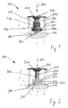
- Die Erfindung wird nachstehend anhand von Ausführungsbeispielen unter Bezugnahme auf die Zeichnungen näher erläutert. Es zeigen:
- Fig. 1
- ein System mit einem ersten Gegenstand und einem zweiten Gegenstand jeweils im Querschnitt sowie mit einer Vorrichtung zur Befestigung des ersten Gegenstands an dem zweiten Gegenstand und
- Fig. 2
- ein System mit einem ersten Gegenstand und einem zweiten Gegenstand jeweils im Querschnitt sowie mit einer alternativen Vorrichtung zur Befestigung des ersten Gegenstands an dem zweiten Gegenstand.
- In
Fig. 1 ist ein System 100 dargestellt, das einen ersten Gegenstand 101, einen zweiten Gegenstand 102 und eine Vorrichtung 120, mittels welcher der erste Gegenstand 101 in einer Befestigungsrichtung 110 an dem zweiten Gegenstand 102 befestigt ist. Die Vorrichtung 120 weist einen Kopf 130 und einen von dem Kopf 130 in der Befestigungsrichtung 110 abragenden Schaft 140 auf. Der Schaft 140 weist eine Anlagefläche 180 auf, welche in der Befestigungsrichtung 110 an dem zweiten Gegenstand 102 anliegt. Der Kopf 130 weist eine in die Befestigungsrichtung 110 weisende Kopfunterseite oder Auflagefläche 150 auf, welche auf dem ersten Gegenstand 101 aufliegt und in der Befestigungsrichtung 110 zur Anlagefläche 180 einen Abstand h1 aufweist. - Zwischen dem Schaft 140, der Auflagefläche 150, dem ersten Gegenstand 101 und dem zweiten Gegenstand 102 ist ein Raum 160 für Ausgleichsbewegungen des ersten Gegenstands 101 quer zur Befestigungsrichtung 110 gebildet. Der Schaft 140 weist einen Stützbund 170 auf, welcher den übrigen Schaft 140 quer zur Befestigungsrichtung 110 überragt, also die breiteste Stelle des Schaftes 140 umfasst. Der Stützbund 170 begrenzt den Raum 160 quer zur Befestigungsrichtung 110, so dass der erste Gegenstand 101 im Falle von Ausgleichsbewegungen gegenüber der Vorrichtung 120 an den Stützbund 170 und nicht an den übrigen Schaft 140 anstösst. Der Stützbund 170 weist in der Befestigungsrichtung 110 zur Anlagefläche 150 einen Abstand h2 und zur Auflagefläche 150 einen Abstand h1-h2 auf, wobei h2 < h1-h2. Dadurch stösst der erste Gegenstand 101 in der Nähe der Anlagefläche 180 an den Schaft 140, so dass die dabei auftretenden Kräfte oder Drehmomente relativ gering sind.
- Der erste Gegenstand 101 umfasst vorliegend einen Gitterrost, von dem zwei zueinander parallele Gitterroststäbe mit einem Abstand b zueinander dargestellt sind, zwischen denen die Vorrichtung 120 angeordnet ist. Der Stützbund 170 hat als grösste Ausdehnung quer zur Befestigungsrichtung 110 eine Breite a, welche das 0,7-fache des Abstands b beträgt.
- Die Auflagefläche 150 überragt den Stützbund 170 quer zur Befestigungsrichtung 110. Der erste Gegenstand 101 ist unmittelbar zwischen der Auflagefläche 150 und dem zweiten Gegenstand 102 eingeklemmt. Einer Ausgleichsbewegung des ersten Gegenstands 101 gegenüber der Vorrichtung 120 wirkt daher zunächst eine relativ kleine Kraft entgegen, nämlich die Reibungskraft aufgrund der Klemmung. Sobald der erste Gegenstand 101 an dem Stützbund 170 anstösst, wirkt der Ausgleichsbewegung eine relativ grosse Kraft entgegen, ohne dass die Vorrichtung 120 oder ihre Verbindung zu dem zweiten Gegenstand 102 beschädigt wird.
- Der Schaft 140 umfasst ein Befestigungsteil 141 für eine unmittelbare Befestigung an dem zweiten Gegenstand, wie beispielsweise einen Nagel, eine Schraube, einen Dübel oder einen Gewindebolzen, und ein von dem Befestigungsteil 141 separates Anbauteil 142 für eine unmittelbare Befestigung an dem Befestigungsteil 141, beispielsweise durch Aufschrauben. Vorliegend weist das Anbauteil 142 den Stützbund 170 auf. Der Schaft 140 umfasst dabei ein Kernteil 143 und ein das Kernteil 143 umschliessendes Ringteil 144, wobei das Ringteil 144 den Stützbund 170 aufweist. Das Ringteil 144 ist beispielsweise auf das Kernteil 143 aufgesteckt oder aufgepresst. Der Stützbund 170 weist quer zur Befestigungsrichtung 110 einen kreisringförmigen Umfang auf.
- In
Fig. 2 ist ein System 200 dargestellt, das einen ersten Gegenstand 201, einen zweiten Gegenstand 202 und eine Vorrichtung 220, mittels welcher der erste Gegenstand 201 in einer Befestigungsrichtung 210 an dem zweiten Gegenstand 202 befestigt ist. Die Vorrichtung 220 weist einen Kopf 230 und einen von dem Kopf 230 in der Befestigungsrichtung 210 abragenden Schaft 240 auf. Der Schaft 240 weist eine Anlagefläche 280 auf, welche in der Befestigungsrichtung 210 an dem zweiten Gegenstand 202 anliegt. Der Kopf 230 weist eine in die Befestigungsrichtung 210 weisende Kopfunterseite oder Auflagefläche 250 auf, welche auf dem ersten Gegenstand 201 aufliegt und in der Befestigungsrichtung 210 zur Anlagefläche 280 einen Abstand h1 aufweist. - Zwischen dem Schaft 240, der Auflagefläche 250, dem ersten Gegenstand 201 und dem zweiten Gegenstand 202 ist ein Raum 260 für Ausgleichsbewegungen des ersten Gegenstands 201 quer zur Befestigungsrichtung 210 gebildet. Der Schaft 240 weist einen Stützbund 270 auf, welcher den übrigen Schaft 240 quer zur Befestigungsrichtung 210 überragt, also die breiteste Stelle des Schaftes 240 umfasst. Der Stützbund 270 begrenzt den Raum 260 quer zur Befestigungsrichtung 210, so dass der erste Gegenstand 201 im Falle von Ausgleichsbewegungen gegenüber der Vorrichtung 220 an den Stützbund 270 und nicht an den übrigen Schaft 240 anstösst. Der Stützbund 270 weist in der Befestigungsrichtung 210 zur Anlagefläche 250 einen Abstand h2 und zur Auflagefläche 250 einen Abstand h1-h2 auf, wobei h2 < h1-h2. Dadurch stösst der erste Gegenstand 201 in der Nähe der Anlagefläche 280 an den Schaft 240, so dass die dabei auftretenden Kräfte oder Drehmomente relativ gering sind.
- Der erste Gegenstand 201 umfasst vorliegend einen Gitterrost, von dem zwei zueinander parallele Gitterroststäbe mit einem Abstand b zueinander dargestellt sind, zwischen denen die Vorrichtung 220 angeordnet ist. Der Stützbund 270 hat quer zur Befestigungsrichtung 210 eine Breite a, welche das 0,7-fache des Abstands b beträgt. Darüber hinaus weist der Stützbund 270 einen Flansch 271 und an dem Flansch 271 die Anlagefläche 280 auf.
- Der erste Gegenstand 201 ist unmittelbar zwischen der Auflagefläche 250 und dem Stützbund 270, vorliegend dem Flansch 271 eingeklemmt. Einer Ausgleichsbewegung des ersten Gegenstands 201 gegenüber der Vorrichtung 220 wirkt daher zunächst eine relativ kleine Kraft entgegen, nämlich die Reibungskraft aufgrund der Klemmung. Sobald der erste Gegenstand 201 an dem Stützbund 270 anstösst, wirkt der Ausgleichsbewegung eine relativ grosse Kraft entgegen, ohne dass die Vorrichtung 220 oder ihre Verbindung zu dem zweiten Gegenstand 202 beschädigt wird.
- Der Schaft 240 umfasst ein Befestigungsteil 241 für eine unmittelbare Befestigung an dem zweiten Gegenstand, wie beispielsweise einen Nagel, eine Schraube, einen Dübel oder einen Gewindebolzen, und ein von dem Befestigungsteil 241 separates Anbauteil 242 für eine unmittelbare Befestigung an dem Befestigungsteil 241, beispielsweise durch Aufschrauben. Vorliegend weist das Befestigungsteil 241 den Stützbund 270 auf. Der Stützbund 270 weist quer zur Befestigungsrichtung 210 einen kreisringförmigen Umfang auf.
- Die Erfindung wurde anhand von Beispielen einer Vorrichtung zur Befestigung eines ersten Gegenstandes an einem zweiten Gegenstand beschrieben. Die Merkmale der beschriebenen Ausführungsformen sind dabei auch beliebig miteinander innerhalb einer einzigen Befestigungsvorrichtung kombinierbar. Es wird darauf hingewiesen, dass die erfindungsgemässe Vorrichtung und das erfindungsgemässe Verfahren auch für andere Zwecke geeignet sind.
Claims (15)
- Vorrichtung zur Befestigung eines ersten Gegenstandes an einem zweiten Gegenstand, mit einem Kopf und einem von dem Kopf in einer Befestigungsrichtung abragenden Schaft für eine unmittelbare Befestigung an dem zweiten Gegenstand, wobei der Kopf eine in die Befestigungsrichtung weisende Auflagefläche für eine Auflage auf dem ersten Gegenstand aufweist, welche in der Befestigungsrichtung nur von dem Schaft überragt wird, wobei der Schaft eine in die Befestigungsrichtung weisende Anlagefläche für eine Anlage an dem zweiten Gegenstand aufweist, dadurch gekennzeichnet, dass der Schaft einen den übrigen Schaft quer zur Befestigungsrichtung überragenden Stützbund aufweist, welcher in der Befestigungsrichtung zur Anlagefläche einen kleineren Abstand aufweist als zur Auflagefläche.
- Vorrichtung nach Anspruch 1, wobei die Auflagefläche den Stützbund quer zur Befestigungsrichtung überragt.
- Vorrichtung nach einem der vorhergehenden Ansprüche, wobei der Schaft ein Befestigungsteil für eine unmittelbare Befestigung an dem zweiten Gegenstand und ein von dem Befestigungsteil separates Anbauteil für eine unmittelbare Befestigung an dem Befestigungsteil umfasst.
- Vorrichtung, wobei das Befestigungsteil den Stützbund aufweist.
- Vorrichtung, wobei das Anbauteil den Stützbund aufweist.
- Vorrichtung nach einem der vorhergehenden Ansprüche, wobei der Stützbund die Anlagefläche aufweist.
- Vorrichtung nach einem der vorhergehenden Ansprüche, wobei der Schaft ein Kernteil und ein das Kernteil umschliessendes Ringteil umfasst, wobei das Ringteil den Stützbund aufweist.
- Vorrichtung nach einem der vorhergehenden Ansprüche, wobei der Stützbund quer zur Befestigungsrichtung einen kreisringförmigen Umfang aufweist.
- System, umfassend einen ersten Gegenstand, einen zweiten Gegenstand und eine Vorrichtung, wobei der erste Gegenstand mittels der Vorrichtung in einer Befestigungsrichtung an dem zweiten Gegenstand befestigt ist, wobei die Vorrichtung einen Kopf und einen von dem Kopf in der Befestigungsrichtung abragenden Schaft aufweist, wobei der Kopf eine in die Befestigungsrichtung weisende Auflagefläche aufweist, welche auf dem ersten Gegenstand aufliegt, wobei zwischen dem Schaft, der Auflagefläche, dem ersten Gegenstand und dem zweiten Gegenstand ein Raum für Ausgleichsbewegungen des ersten Gegenstands quer zur Befestigungsrichtung gebildet ist, dadurch gekennzeichnet, dass der Schaft einen den Raum quer zur Befestigungsrichtung begrenzenden Stützbund aufweist, welcher in der Befestigungsrichtung zur Anlagefläche einen kleineren Abstand aufweist als zur Auflagefläche.
- System nach Anspruch 9, wobei der erste Gegenstand unmittelbar zwischen der Auflagefläche und dem zweiten Gegenstand eingeklemmt ist.
- System nach Anspruch 9, wobei der erste Gegenstand unmittelbar zwischen der Auflagefläche und dem Stützbund eingeklemmt ist.
- System nach einem der Ansprüche 9 bis 11, wobei der erste Gegenstand ein Gitterrost ist.
- System nach Anspruch 12, wobei der Stützbund als grösste Ausdehnung quer zur Befestigungsrichtung eine Breite a hat und der Gitterrost zwei zueinander parallele Gitterroststäbe mit einem Abstand b zueinander aufweist, zwischen denen die Vorrichtung angeordnet ist, und wobei die Breite a kleiner als der Abstand b ist.
- System nach Anspruch 13, wobei die Breite a höchstens das 0,8-fache des Abstands b beträgt.
- System nach einem der Ansprüche 13 und 14, wobei die Breite a mindestens halb so gross wie der Abstand b ist.
Priority Applications (2)
| Application Number | Priority Date | Filing Date | Title |
|---|---|---|---|
| EP16167108.6A EP3239535A1 (de) | 2016-04-26 | 2016-04-26 | Befestigungsvorrichtung und system |
| PCT/EP2017/059703 WO2017186660A1 (de) | 2016-04-26 | 2017-04-25 | Befestigungsvorrichtung und system |
Applications Claiming Priority (1)
| Application Number | Priority Date | Filing Date | Title |
|---|---|---|---|
| EP16167108.6A EP3239535A1 (de) | 2016-04-26 | 2016-04-26 | Befestigungsvorrichtung und system |
Publications (1)
| Publication Number | Publication Date |
|---|---|
| EP3239535A1 true EP3239535A1 (de) | 2017-11-01 |
Family
ID=55862572
Family Applications (1)
| Application Number | Title | Priority Date | Filing Date |
|---|---|---|---|
| EP16167108.6A Withdrawn EP3239535A1 (de) | 2016-04-26 | 2016-04-26 | Befestigungsvorrichtung und system |
Country Status (2)
| Country | Link |
|---|---|
| EP (1) | EP3239535A1 (de) |
| WO (1) | WO2017186660A1 (de) |
Citations (2)
| Publication number | Priority date | Publication date | Assignee | Title |
|---|---|---|---|---|
| US20090123252A1 (en) * | 2007-11-14 | 2009-05-14 | Newfrey Llc | Power Seal Bolt Assembly |
| DE102010064427A1 (de) * | 2010-12-14 | 2012-06-14 | Richard Ambros | Selbstsichernde Rändelmutter bzw. Rändelschraube für eine haltbare und rüttelfeste Schraubverbindung zweier Teile |
-
2016
- 2016-04-26 EP EP16167108.6A patent/EP3239535A1/de not_active Withdrawn
-
2017
- 2017-04-25 WO PCT/EP2017/059703 patent/WO2017186660A1/de not_active Ceased
Patent Citations (2)
| Publication number | Priority date | Publication date | Assignee | Title |
|---|---|---|---|---|
| US20090123252A1 (en) * | 2007-11-14 | 2009-05-14 | Newfrey Llc | Power Seal Bolt Assembly |
| DE102010064427A1 (de) * | 2010-12-14 | 2012-06-14 | Richard Ambros | Selbstsichernde Rändelmutter bzw. Rändelschraube für eine haltbare und rüttelfeste Schraubverbindung zweier Teile |
Also Published As
| Publication number | Publication date |
|---|---|
| WO2017186660A1 (de) | 2017-11-02 |
Similar Documents
| Publication | Publication Date | Title |
|---|---|---|
| DE2537582A1 (de) | Befestigungsmittel | |
| DE04785804T1 (de) | Verbessertes zufuhrelement für metallguss | |
| DE102016209846A1 (de) | Keilsicherungsmutteranordnung | |
| EP3286440B2 (de) | Vorrichtung zum festlegen an einem bauteil | |
| EP3412922B1 (de) | Vorrichtung zum festlegen an einem bauteil | |
| EP2085679B1 (de) | Verstellfuß | |
| DE102011100247A1 (de) | Verbindungssystem | |
| DE202016100920U1 (de) | Vorrichtung zur Anordnung einer auskragenden Struktur | |
| EP3323961B1 (de) | Schalungselement für eine betonwandschalung, mit einer vorrichtung zur aufnahme eines schalungsankers | |
| WO2017186660A1 (de) | Befestigungsvorrichtung und system | |
| DE102015210516A1 (de) | Befestigungssystem mit Dünnschaftschraube und Sicherungselement | |
| DE2633612A1 (de) | Elastischer halter oder puffer | |
| EP3402993B1 (de) | Montageanordnung mit montageschiene und überstehender haltemutter | |
| DE102018127768B4 (de) | Beschlag sowie Befestigungsset | |
| DE202021102165U1 (de) | System zur Befestigung | |
| DE102008051326A1 (de) | Befestigungseinrichtung mit einem Clip | |
| EP3368780B1 (de) | Befestigungsanordnung sowie verfahren zur bildung der befestigungsanordnung | |
| EP2591972A2 (de) | Sicherungselement für einen Klammerverschluss für ein Weichenstellsystem | |
| DE102020209623B4 (de) | Montageplatte zur Wandmontage zumindest zweier Installationsfittings, Montagesystem sowie Verfahren zur Montage | |
| DE102018102124A1 (de) | Kraftfahrzeug-Befestigungssystem zum Befestigen eines ersten Kraftfahrzeug-Bauteils an einem zweiten Kraftfahrzeug-Bauteil | |
| DE102017207389A1 (de) | Ausgleichselement | |
| DE102016001705A1 (de) | Fixierelement und Schraubverbindung | |
| DE102016113920A1 (de) | Exzenterbolzen | |
| DE102022103700A1 (de) | Montageclip zum Verbinden von zwei Bauteilen | |
| DE29613893U1 (de) | Verbindungsvorrichtung für Geländer |
Legal Events
| Date | Code | Title | Description |
|---|---|---|---|
| PUAI | Public reference made under article 153(3) epc to a published international application that has entered the european phase |
Free format text: ORIGINAL CODE: 0009012 |
|
| AK | Designated contracting states |
Kind code of ref document: A1 Designated state(s): AL AT BE BG CH CY CZ DE DK EE ES FI FR GB GR HR HU IE IS IT LI LT LU LV MC MK MT NL NO PL PT RO RS SE SI SK SM TR |
|
| AX | Request for extension of the european patent |
Extension state: BA ME |
|
| STAA | Information on the status of an ep patent application or granted ep patent |
Free format text: STATUS: THE APPLICATION IS DEEMED TO BE WITHDRAWN |
|
| 18D | Application deemed to be withdrawn |
Effective date: 20180503 |