EP3239487A1 - Moteur à combustion interne - Google Patents
Moteur à combustion interne Download PDFInfo
- Publication number
- EP3239487A1 EP3239487A1 EP16000958.5A EP16000958A EP3239487A1 EP 3239487 A1 EP3239487 A1 EP 3239487A1 EP 16000958 A EP16000958 A EP 16000958A EP 3239487 A1 EP3239487 A1 EP 3239487A1
- Authority
- EP
- European Patent Office
- Prior art keywords
- chamber
- internal combustion
- combustion engine
- engine
- orifice
- Prior art date
- Legal status (The legal status is an assumption and is not a legal conclusion. Google has not performed a legal analysis and makes no representation as to the accuracy of the status listed.)
- Granted
Links
- 238000002485 combustion reaction Methods 0.000 title claims abstract description 75
- 239000000446 fuel Substances 0.000 claims abstract description 57
- 239000012530 fluid Substances 0.000 claims abstract description 7
- 239000007921 spray Substances 0.000 claims description 16
- 239000000203 mixture Substances 0.000 claims description 8
- 230000000694 effects Effects 0.000 description 5
- 238000005259 measurement Methods 0.000 description 5
- 230000007423 decrease Effects 0.000 description 4
- 230000003247 decreasing effect Effects 0.000 description 3
- 238000010438 heat treatment Methods 0.000 description 3
- 238000005086 pumping Methods 0.000 description 3
- 238000010791 quenching Methods 0.000 description 3
- 230000000171 quenching effect Effects 0.000 description 3
- 230000003116 impacting effect Effects 0.000 description 2
- 230000035515 penetration Effects 0.000 description 2
- 150000003254 radicals Chemical class 0.000 description 2
- 239000000126 substance Substances 0.000 description 2
- 230000003197 catalytic effect Effects 0.000 description 1
- 230000002925 chemical effect Effects 0.000 description 1
- 230000001419 dependent effect Effects 0.000 description 1
- 238000007599 discharging Methods 0.000 description 1
- 230000003993 interaction Effects 0.000 description 1
- 230000008685 targeting Effects 0.000 description 1
Images


Classifications
-
- F—MECHANICAL ENGINEERING; LIGHTING; HEATING; WEAPONS; BLASTING
- F02—COMBUSTION ENGINES; HOT-GAS OR COMBUSTION-PRODUCT ENGINE PLANTS
- F02B—INTERNAL-COMBUSTION PISTON ENGINES; COMBUSTION ENGINES IN GENERAL
- F02B19/00—Engines characterised by precombustion chambers
- F02B19/10—Engines characterised by precombustion chambers with fuel introduced partly into pre-combustion chamber, and partly into cylinder
- F02B19/1019—Engines characterised by precombustion chambers with fuel introduced partly into pre-combustion chamber, and partly into cylinder with only one pre-combustion chamber
- F02B19/108—Engines characterised by precombustion chambers with fuel introduced partly into pre-combustion chamber, and partly into cylinder with only one pre-combustion chamber with fuel injection at least into pre-combustion chamber, i.e. injector mounted directly in the pre-combustion chamber
- F02B19/1085—Engines characterised by precombustion chambers with fuel introduced partly into pre-combustion chamber, and partly into cylinder with only one pre-combustion chamber with fuel injection at least into pre-combustion chamber, i.e. injector mounted directly in the pre-combustion chamber controlling fuel injection
-
- F—MECHANICAL ENGINEERING; LIGHTING; HEATING; WEAPONS; BLASTING
- F02—COMBUSTION ENGINES; HOT-GAS OR COMBUSTION-PRODUCT ENGINE PLANTS
- F02B—INTERNAL-COMBUSTION PISTON ENGINES; COMBUSTION ENGINES IN GENERAL
- F02B19/00—Engines characterised by precombustion chambers
- F02B19/10—Engines characterised by precombustion chambers with fuel introduced partly into pre-combustion chamber, and partly into cylinder
- F02B19/1019—Engines characterised by precombustion chambers with fuel introduced partly into pre-combustion chamber, and partly into cylinder with only one pre-combustion chamber
- F02B19/108—Engines characterised by precombustion chambers with fuel introduced partly into pre-combustion chamber, and partly into cylinder with only one pre-combustion chamber with fuel injection at least into pre-combustion chamber, i.e. injector mounted directly in the pre-combustion chamber
-
- F—MECHANICAL ENGINEERING; LIGHTING; HEATING; WEAPONS; BLASTING
- F02—COMBUSTION ENGINES; HOT-GAS OR COMBUSTION-PRODUCT ENGINE PLANTS
- F02B—INTERNAL-COMBUSTION PISTON ENGINES; COMBUSTION ENGINES IN GENERAL
- F02B19/00—Engines characterised by precombustion chambers
- F02B19/10—Engines characterised by precombustion chambers with fuel introduced partly into pre-combustion chamber, and partly into cylinder
- F02B19/1019—Engines characterised by precombustion chambers with fuel introduced partly into pre-combustion chamber, and partly into cylinder with only one pre-combustion chamber
- F02B19/1023—Engines characterised by precombustion chambers with fuel introduced partly into pre-combustion chamber, and partly into cylinder with only one pre-combustion chamber pre-combustion chamber and cylinder being fed with fuel-air mixture(s)
- F02B19/1028—Engines characterised by precombustion chambers with fuel introduced partly into pre-combustion chamber, and partly into cylinder with only one pre-combustion chamber pre-combustion chamber and cylinder being fed with fuel-air mixture(s) pre-combustion chamber and cylinder having both intake ports or valves, e.g. HONDS CVCC
- F02B19/1057—Engines characterised by precombustion chambers with fuel introduced partly into pre-combustion chamber, and partly into cylinder with only one pre-combustion chamber pre-combustion chamber and cylinder being fed with fuel-air mixture(s) pre-combustion chamber and cylinder having both intake ports or valves, e.g. HONDS CVCC with fuel injectors disposed upstream of intake valves
-
- F—MECHANICAL ENGINEERING; LIGHTING; HEATING; WEAPONS; BLASTING
- F02—COMBUSTION ENGINES; HOT-GAS OR COMBUSTION-PRODUCT ENGINE PLANTS
- F02B—INTERNAL-COMBUSTION PISTON ENGINES; COMBUSTION ENGINES IN GENERAL
- F02B19/00—Engines characterised by precombustion chambers
- F02B19/10—Engines characterised by precombustion chambers with fuel introduced partly into pre-combustion chamber, and partly into cylinder
- F02B19/1004—Engines characterised by precombustion chambers with fuel introduced partly into pre-combustion chamber, and partly into cylinder details of combustion chamber, e.g. mounting arrangements
- F02B19/1014—Engines characterised by precombustion chambers with fuel introduced partly into pre-combustion chamber, and partly into cylinder details of combustion chamber, e.g. mounting arrangements design parameters, e.g. volume, torch passage cross sectional area, length, orientation, or the like
-
- F—MECHANICAL ENGINEERING; LIGHTING; HEATING; WEAPONS; BLASTING
- F02—COMBUSTION ENGINES; HOT-GAS OR COMBUSTION-PRODUCT ENGINE PLANTS
- F02B—INTERNAL-COMBUSTION PISTON ENGINES; COMBUSTION ENGINES IN GENERAL
- F02B19/00—Engines characterised by precombustion chambers
- F02B19/10—Engines characterised by precombustion chambers with fuel introduced partly into pre-combustion chamber, and partly into cylinder
- F02B19/1019—Engines characterised by precombustion chambers with fuel introduced partly into pre-combustion chamber, and partly into cylinder with only one pre-combustion chamber
- F02B19/1023—Engines characterised by precombustion chambers with fuel introduced partly into pre-combustion chamber, and partly into cylinder with only one pre-combustion chamber pre-combustion chamber and cylinder being fed with fuel-air mixture(s)
- F02B19/1028—Engines characterised by precombustion chambers with fuel introduced partly into pre-combustion chamber, and partly into cylinder with only one pre-combustion chamber pre-combustion chamber and cylinder being fed with fuel-air mixture(s) pre-combustion chamber and cylinder having both intake ports or valves, e.g. HONDS CVCC
-
- F—MECHANICAL ENGINEERING; LIGHTING; HEATING; WEAPONS; BLASTING
- F02—COMBUSTION ENGINES; HOT-GAS OR COMBUSTION-PRODUCT ENGINE PLANTS
- F02B—INTERNAL-COMBUSTION PISTON ENGINES; COMBUSTION ENGINES IN GENERAL
- F02B19/00—Engines characterised by precombustion chambers
- F02B19/12—Engines characterised by precombustion chambers with positive ignition
-
- F—MECHANICAL ENGINEERING; LIGHTING; HEATING; WEAPONS; BLASTING
- F02—COMBUSTION ENGINES; HOT-GAS OR COMBUSTION-PRODUCT ENGINE PLANTS
- F02B—INTERNAL-COMBUSTION PISTON ENGINES; COMBUSTION ENGINES IN GENERAL
- F02B19/00—Engines characterised by precombustion chambers
- F02B19/16—Chamber shapes or constructions not specific to sub-groups F02B19/02 - F02B19/10
- F02B19/18—Transfer passages between chamber and cylinder
-
- F—MECHANICAL ENGINEERING; LIGHTING; HEATING; WEAPONS; BLASTING
- F02—COMBUSTION ENGINES; HOT-GAS OR COMBUSTION-PRODUCT ENGINE PLANTS
- F02D—CONTROLLING COMBUSTION ENGINES
- F02D41/00—Electrical control of supply of combustible mixture or its constituents
- F02D41/30—Controlling fuel injection
- F02D41/3094—Controlling fuel injection the fuel injection being effected by at least two different injectors, e.g. one in the intake manifold and one in the cylinder
-
- F—MECHANICAL ENGINEERING; LIGHTING; HEATING; WEAPONS; BLASTING
- F02—COMBUSTION ENGINES; HOT-GAS OR COMBUSTION-PRODUCT ENGINE PLANTS
- F02M—SUPPLYING COMBUSTION ENGINES IN GENERAL WITH COMBUSTIBLE MIXTURES OR CONSTITUENTS THEREOF
- F02M61/00—Fuel-injectors not provided for in groups F02M39/00 - F02M57/00 or F02M67/00
- F02M61/14—Arrangements of injectors with respect to engines; Mounting of injectors
- F02M61/145—Arrangements of injectors with respect to engines; Mounting of injectors the injection nozzle opening into the air intake conduit
-
- F—MECHANICAL ENGINEERING; LIGHTING; HEATING; WEAPONS; BLASTING
- F02—COMBUSTION ENGINES; HOT-GAS OR COMBUSTION-PRODUCT ENGINE PLANTS
- F02P—IGNITION, OTHER THAN COMPRESSION IGNITION, FOR INTERNAL-COMBUSTION ENGINES; TESTING OF IGNITION TIMING IN COMPRESSION-IGNITION ENGINES
- F02P13/00—Sparking plugs structurally combined with other parts of internal-combustion engines
-
- F—MECHANICAL ENGINEERING; LIGHTING; HEATING; WEAPONS; BLASTING
- F02—COMBUSTION ENGINES; HOT-GAS OR COMBUSTION-PRODUCT ENGINE PLANTS
- F02P—IGNITION, OTHER THAN COMPRESSION IGNITION, FOR INTERNAL-COMBUSTION ENGINES; TESTING OF IGNITION TIMING IN COMPRESSION-IGNITION ENGINES
- F02P9/00—Electric spark ignition control, not otherwise provided for
- F02P9/002—Control of spark intensity, intensifying, lengthening, suppression
- F02P9/007—Control of spark intensity, intensifying, lengthening, suppression by supplementary electrical discharge in the pre-ionised electrode interspace of the sparking plug, e.g. plasma jet ignition
-
- F—MECHANICAL ENGINEERING; LIGHTING; HEATING; WEAPONS; BLASTING
- F02—COMBUSTION ENGINES; HOT-GAS OR COMBUSTION-PRODUCT ENGINE PLANTS
- F02M—SUPPLYING COMBUSTION ENGINES IN GENERAL WITH COMBUSTIBLE MIXTURES OR CONSTITUENTS THEREOF
- F02M57/00—Fuel-injectors combined or associated with other devices
- F02M57/06—Fuel-injectors combined or associated with other devices the devices being sparking plugs
-
- F—MECHANICAL ENGINEERING; LIGHTING; HEATING; WEAPONS; BLASTING
- F02—COMBUSTION ENGINES; HOT-GAS OR COMBUSTION-PRODUCT ENGINE PLANTS
- F02P—IGNITION, OTHER THAN COMPRESSION IGNITION, FOR INTERNAL-COMBUSTION ENGINES; TESTING OF IGNITION TIMING IN COMPRESSION-IGNITION ENGINES
- F02P15/00—Electric spark ignition having characteristics not provided for in, or of interest apart from, groups F02P1/00 - F02P13/00 and combined with layout of ignition circuits
- F02P15/08—Electric spark ignition having characteristics not provided for in, or of interest apart from, groups F02P1/00 - F02P13/00 and combined with layout of ignition circuits having multiple-spark ignition, i.e. ignition occurring simultaneously at different places in one engine cylinder or in two or more separate engine cylinders
-
- F—MECHANICAL ENGINEERING; LIGHTING; HEATING; WEAPONS; BLASTING
- F02—COMBUSTION ENGINES; HOT-GAS OR COMBUSTION-PRODUCT ENGINE PLANTS
- F02P—IGNITION, OTHER THAN COMPRESSION IGNITION, FOR INTERNAL-COMBUSTION ENGINES; TESTING OF IGNITION TIMING IN COMPRESSION-IGNITION ENGINES
- F02P15/00—Electric spark ignition having characteristics not provided for in, or of interest apart from, groups F02P1/00 - F02P13/00 and combined with layout of ignition circuits
- F02P15/10—Electric spark ignition having characteristics not provided for in, or of interest apart from, groups F02P1/00 - F02P13/00 and combined with layout of ignition circuits having continuous electric sparks
-
- Y—GENERAL TAGGING OF NEW TECHNOLOGICAL DEVELOPMENTS; GENERAL TAGGING OF CROSS-SECTIONAL TECHNOLOGIES SPANNING OVER SEVERAL SECTIONS OF THE IPC; TECHNICAL SUBJECTS COVERED BY FORMER USPC CROSS-REFERENCE ART COLLECTIONS [XRACs] AND DIGESTS
- Y02—TECHNOLOGIES OR APPLICATIONS FOR MITIGATION OR ADAPTATION AGAINST CLIMATE CHANGE
- Y02T—CLIMATE CHANGE MITIGATION TECHNOLOGIES RELATED TO TRANSPORTATION
- Y02T10/00—Road transport of goods or passengers
- Y02T10/10—Internal combustion engine [ICE] based vehicles
- Y02T10/12—Improving ICE efficiencies
Definitions
- the present invention relates to an internal combustion engine according to the independent claim.
- the invention refers to the field of internal combustion engines utilizing spark ignition.
- Lean combustion with ⁇ in the approximate range of 1 ⁇ ⁇ ⁇ 1.5 has been proven to increase net thermal efficiency compared to combustion with lower ⁇ , however it also increase NOx emissions so as to necessitate catalytic converters.
- Ultra-lean combustion with ⁇ > 1.5 has demonstrated the ability to both increase net thermal efficiency and significantly reduce NOx emissions.
- the major limitation in ultra-lean combustion systems is the poor ignition quality of the mixture which results in a "lean limit" for values of A above which the combustion engine does not ignite.
- An internal combustion engine for TJI comprises an ignition system having at least one pre-chamber with a fuel injector and an ignition device arranged therein.
- the ignition device is capable of turbulent jet ignition which enables ultra-lean operation by utilizing radical turbulent jets emerging from the pre-chamber to provide the ignition source for the main chamber.
- the pre-chamber is small compared to the main chamber volume and has multiple orifices to produce multiple, distributed ignition sites throughout the main chamber.
- the orifices are of a small size to allow for flame quenching as the combustion products exit out of the pre-chamber into the main combustion chamber.
- the combustion products then react with the main fuel charge and initiate combustion in the main combustion chamber at multiple locations through chemical, thermal and turbulent effects some distance away from the pre-chamber nozzle.
- the chemical effect is caused by radical species present in the jet which are highly reactive so as to be capable of igniting the air-fuel mixture present in the main chamber.
- Thermal effects are caused by partially or fully burned combustion products which enter the main chamber at an elevated temperature capable of triggering the main chamber combustion.
- the turbulent effect ensures interaction between the turbulent jets and the charge in the main chamber.
- the internal combustion engine has an engine block with one or more cylinders.
- Each cylinder has a cylinder head bordering a main combustion chamber in which the main air fuel charge is ignited.
- a piston is arranged bordering the combustion chamber which is connected via a rod at a crankshaft so as to allow a reciprocal movement.
- Each cylinder head defines an intake opening and an exhaust opening. The intake and exhaust openings are opened and closed via cam driven valves to provide fluid communication between the cylinder and an intake manifold and an exhaust manifold.
- the internal combustion engine also includes a fuel injector mounted in the intake manifold as a means of introducing the main fuel/air charge into the combustion chamber through the intake port.
- the ignition device has an igniter portion and an injector arranged to face an inner pre-chamber volume.
- the pre-chamber is shaped so as to form a nozzle having a plurality of orifices disposed spaced from one another and providing fluid communication between the pre-chamber and the combustion chamber.
- the igniter portion ignites the fuel in the pre-chamber.
- the orifice diameter is kept small to promote flame quenching as the combustion products exit out of the pre-chamber into the main combustion chamber. Flame quenching means that the partially combusted pre-chamber products are forced through the small orifices of the pre-chamber.
- the combustion products are extinguished but dispersed through the main combustion chamber then react with the main fuel charge and initiates combustion in the main fuel chamber at multiple locations through chemical, thermal and turbulent effects some distance away from the pre-chamber nozzle.
- the pre-chamber of the ignition device includes a plurality of orifices to provide a fluid communication between the pre-chamber volume and the main chamber volume.
- the orifices are limited to a range of specific maximum and minimum diameters while the pre-chamber volume is kept in a specific range.
- This design is chosen only for a proper targeting of nozzle characteristics such as orifice diameter, number of orifices in relation to pre-chamber volume.
- the disadvantage related to known designs is that it only relates to physical jet properties such as velocity, penetration and ignition site distribution to a range of pre-chamber volumes.
- an object of the invention to provide an internal combustion engine with improved thermal efficiency and which takes into account the design (i.e. size) of the main combustion chamber and in particular the design (i.e. size) of the orifices in relation to the diameter of the engine bore.
- the present invention comprises an internal combustion engine having at least one cylinder and a piston supported for repeated reciprocal movement in the cylinder so as to define a combustion chamber of an engine bore diameter (A-A).
- the internal combustion engine further comprises an ignition device arranged in said cylinder (the ignition device) having an igniter portion and an fuel injector which are both arranged in a pre-chamber, wherein the pre-chamber comprises a plurality of orifices for providing fluid communication between said pre-chamber and the combustion chamber.
- the plurality of orifices are of an overall orifice area so that the ratio between the overall orifice area and the engine bore diameter (A-A) ranges from 0.01 mm to 0.2 mm.
- the engine bore diameter is in other words the bore of the engine or the diameter of the cylinder.
- the ratio between the overall orifice area size and the engine bore diameter ranges from 0.016 mm to 0.16 mm (i.e. from 0.05 mm to 0.09 mm). In a particularly preferred ratio between the overall orifice area size and the engine bore diameter is 0.06 mm. These ranges represent the optimum results in experimental measurements which have shown a maximum in net thermal efficiency.
- Another preferred aspect relates to that the number of orifices is in the range of 4 to 8, and wherein diameter of the orifice is in the range of 0.7 mm to 1.55 mm.
- the given values are particularly of interest in combination with a combustion engine having an engine bore diameter (A-A) of 87.5 mm.
- each orifice has a first surface area facing the pre-chamber and a second surface area facing the combustion chamber, and wherein the ratio of the size of the first surface area and the size of the second surface area is in the range of 0.5 to 2. Varying the ratio allows for changing the form of the jet emanating from the orifice, i.e. a reduction results in a convergent jet, while an increase in surface area results in a divergent jet.
- the inner volume of the pre-chamber is less than 5 % and in particular the range of 0.3 % to 3 % of the minimum volume of the combustion chamber. Measurements have shown that larger pre-chamber volumes than this result in a decrease in net thermal efficiency.
- Another preferred aspect relates to that such an orifice is arranged in the pre-chamber so that the centerline of the orifice (C-C) has an angle in the range of 50° to 60° relative to the central axis of the pre-chamber (B-B). It is further preferred to arrange the orifices in multiple parallel planes (e.g. a first number of orifices (e.g. three in a six orifice nozzle) in a first plane and second number of orifices (e.g. three) in a second plane having a respective angle between orifice centerline and central axis of the pre-chamber of 50° and 60°. These angles provide a good combustion efficiency. Changing the angle from 50° to 60° has shown to allow for increasing the lean limit from 1.7 ⁇ to 2.1 ⁇ .
- the fuel injector is arranged in the pre-chamber so that the centerline of the fuel spray (D-D) has an angle in the range of 20° to 60° relative to the central axis of the pre-chamber (B-B).
- This allows for a good mixing of air and fuel in the pre-chamber, i.e. the fuel spray interacts with air charge entering the pre-chamber via the orifices.
- Fuel spray centerline angles less than 20° will result in fuel directly impacting the spark plug, thereby impeding ignition.
- Fuel spray centerline angles greater than 60° will result in fuel directly impacting the orifices and exiting through those orifices, thereby exiting the pre-chamber prior to ignition.
- the ignition device comprises a control unit capable of that the fuel injector injects fuel spray pulses into the pre-chamber in a manner so that a rich fuel mixture is present near the walls of the pre-chamber and a rich mixture is present in the area near the spark plug electrode.
- a control unit capable of that the fuel injector injects fuel spray pulses into the pre-chamber in a manner so that a rich fuel mixture is present near the walls of the pre-chamber and a rich mixture is present in the area near the spark plug electrode.
- the ignition device comprises a control unit capable of that the fuel injector is capable of injecting fuel spray pulses into the pre-chamber in a manner so that in between of consecutive fuel spray pulses at least two sparks are provided by the igniter portion.
- the further ignition spark allows for more complete combustion of the contents in the pre-chamber, thereby increasing the quantity of energy released in the pre-chamber during the pre-chamber combustion event and increasing jet velocity.
- Fig. 1 depicts an internal combustion engine 1 comprising one cylinder 2 (of e.g. four).
- the cylinder 2 is formed in an engine block 21 and a cylinder head 22 is arranged thereon.
- An inlet 221 with a separate main fuel injector 5 and an outlet 222 for discharging the combusted products are arranged in cylinder head 21.
- a piston 3 is supported (at a crank shaft - not shown below) for repeated reciprocal movement in the cylinder 2 so as to define (together with the cylinder head) a combustion chamber 21 having an engine bore diameter (A-A) which is in the shown example 87.5 mm.
- A-A engine bore diameter
- Internal combustion engine 1 further comprises an ignition device 4 (for turbulent jet ignition) arranged in said cylinder 2 having an igniter portion 42 and an fuel injector 43 (separate from the main fuel injector) which are both arranged facing a pre-chamber 41.
- Pre-chamber 41 comprises in the shown example six orifices 44 for providing fluid communication from inside of pre-chamber 41 to combustion chamber 21.
- the orifices 44 are of an overall orifice area (aggregate area of all individual orifice areas) of 5.70 mm 2 so that the ratio between the overall orifice area and an engine bore diameter (A-A) is 0.065 mm.
- the overall orifice area size in the pre-chamber 44 is the number of six orifices multiplied by the individual orifice area of 5.70 mm 2 .
- the engine bore diameter is in the present example 87.5 mm.
- the achieved net thermal efficiency is 42,1 %. That maximum in net thermal efficiency is unexpected in view of prior art publications which state that net thermal efficiency is maximized with decreasing nozzle orifice area.
- Net thermal efficiency is calculated as engine work divided by fuel energy, wherein the engine work is combustion work and the pumping work, and wherein the fuel energy is the fuel flow multiplied by the fuel heating value.
- the dimensions provide an orifice area small enough to avoid low jet velocities and which is large enough to avoid a choked flow and, therewith, reduced temperatures of the jet.
- the ignition device 4 comprises in the present example a control unit (not depicted) capable of controlling the fuel injector 43 so as to injecting multiple fuel spray pulses into the pre-chamber 41 in a given cycle so that a rich mixture exists near the igniter portion 42 and a rich mixture exists near the pre-chamber walls.
- a control unit capable of controlling the fuel injector 43 so as to injecting multiple fuel spray pulses into the pre-chamber 41 in a given cycle so that a rich mixture exists near the igniter portion 42 and a rich mixture exists near the pre-chamber walls.
- the ignition device 4 comprises a control unit (not depicted) capable of controlling the fuel injector 43 so that it injects fuel spray pulses into the pre-chamber 41 in a manner so that more than one fuel spray pulse is injected in between of consecutive sparks provided by the igniter portion 42.
- pre-chamber 41 is arranged on top of a combustion chamber (main chamber) in the cylinder head 22 of an internal combustion engine.
- the pre-chamber 41 comprises a number of orifices 44, wherein each orifice 44 has a first (inner) surface area 441 facing the pre-chamber 41 and a second (outer) surface area 442 facing the combustion chamber.
- the ratio of the size of the first surface area 441 and the size of the second surface area 442 is in the shown example 1 which means that both areas are of the same size. Since the ratio correlates to the form of the emanating jet, the jet in this example (ration 1) is (ideally) parallel.
- Each orifice 44 is arranged in the pre-chamber 41 so that the centerline of the orifice C-C has an angle of 60° (lower angle between B-B and C-C) relative to the central axis of the pre-chamber B-B.
- the fuel injector 43 is arranged in the pre-chamber 41 and is designed so that the centerline of the fuel spray D-D has an angle (upper angle between B-B and D-D) of 20° relative to the central axis of the pre-chamber B-B.
- Fig. 3 provides a graph for a measurement of the net thermal efficiency against the ratio of the overall orifice for the examples of specific dimensions provided as table in the following.
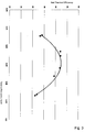
- Fig. 4 is a graphical representation of inner volume of the pre-chamber against the net thermal efficiency, wherein the pre-chamber volume of less than 5 % and in particular the range of 0.3 % to 3 % of the minimum volume of the combustion chamber. Minimum volume is for the piston arranged in the upper top dead position. Measurements for larger pre-chamber volumes result in a decrease in net thermal efficiency.
- the shown measurements represent net thermal efficiency against pre-chamber volume in % of minimum main chamber combustion volume, wherein graph 1 is for 1500 rpm/3.9barIMPEg/L2, graph 2 is for 1500 rpm/3.9barIMPEg/L1.9, graph 3 is for 1500 rpm/3.9barIMPEg/L1.8 and graph 4 is for 4000 rpm/7,87barIMPEg/L1.5.
Landscapes
- Engineering & Computer Science (AREA)
- Chemical & Material Sciences (AREA)
- Combustion & Propulsion (AREA)
- Mechanical Engineering (AREA)
- General Engineering & Computer Science (AREA)
- Physics & Mathematics (AREA)
- Plasma & Fusion (AREA)
- Combustion Methods Of Internal-Combustion Engines (AREA)
- Fuel-Injection Apparatus (AREA)
Priority Applications (5)
| Application Number | Priority Date | Filing Date | Title |
|---|---|---|---|
| EP16000958.5A EP3239487B1 (fr) | 2016-04-28 | 2016-04-28 | Moteur à combustion interne avec préchambre à allumage par jet optimisée |
| JP2017011081A JP6383820B2 (ja) | 2016-04-28 | 2017-01-25 | 内燃機関 |
| KR1020170022205A KR101950228B1 (ko) | 2016-04-28 | 2017-02-20 | 내연기관 |
| US15/437,884 US10458311B2 (en) | 2016-04-28 | 2017-02-21 | Internal combustion engine |
| CN201710160616.9A CN107339149B (zh) | 2016-04-28 | 2017-03-17 | 内燃机 |
Applications Claiming Priority (1)
| Application Number | Priority Date | Filing Date | Title |
|---|---|---|---|
| EP16000958.5A EP3239487B1 (fr) | 2016-04-28 | 2016-04-28 | Moteur à combustion interne avec préchambre à allumage par jet optimisée |
Publications (2)
| Publication Number | Publication Date |
|---|---|
| EP3239487A1 true EP3239487A1 (fr) | 2017-11-01 |
| EP3239487B1 EP3239487B1 (fr) | 2021-09-01 |
Family
ID=55966963
Family Applications (1)
| Application Number | Title | Priority Date | Filing Date |
|---|---|---|---|
| EP16000958.5A Active EP3239487B1 (fr) | 2016-04-28 | 2016-04-28 | Moteur à combustion interne avec préchambre à allumage par jet optimisée |
Country Status (5)
| Country | Link |
|---|---|
| US (1) | US10458311B2 (fr) |
| EP (1) | EP3239487B1 (fr) |
| JP (1) | JP6383820B2 (fr) |
| KR (1) | KR101950228B1 (fr) |
| CN (1) | CN107339149B (fr) |
Cited By (1)
| Publication number | Priority date | Publication date | Assignee | Title |
|---|---|---|---|---|
| WO2021173107A1 (fr) * | 2020-02-24 | 2021-09-02 | Mahle International Gmbh | Moteur à allumage par étincelles doté d'une préchambre, préchambre et pièce rapportée d'adaptateur pour le moteur |
Families Citing this family (13)
| Publication number | Priority date | Publication date | Assignee | Title |
|---|---|---|---|---|
| JP6895243B2 (ja) * | 2016-12-08 | 2021-06-30 | 三菱重工エンジン&ターボチャージャ株式会社 | 副室式ガスエンジン |
| JP6825553B2 (ja) * | 2017-12-28 | 2021-02-03 | トヨタ自動車株式会社 | 内燃機関の制御装置 |
| JP2019152200A (ja) * | 2018-03-06 | 2019-09-12 | 株式会社Soken | エンジンシステム |
| JP2019157638A (ja) * | 2018-03-07 | 2019-09-19 | 株式会社Soken | 副室式点火装置及びそれを備えたエンジン |
| SE542877C2 (en) * | 2018-10-11 | 2020-07-28 | Scania Cv Ab | A pre-chamber arrangement for a gas engine and a gas engine |
| DE102019201344A1 (de) * | 2019-02-01 | 2020-08-06 | Hitachi Automotive Systems, Ltd. | Vorrichtung und Verfahren zum Steuern des Starts einer Brennkraftmaschine |
| CN110185534A (zh) * | 2019-05-16 | 2019-08-30 | 天津大学 | 一种火花辅助射流点火发动机 |
| RU2750830C2 (ru) * | 2019-07-05 | 2021-07-05 | Федеральное государственное автономное образовательное учреждение высшего образования "Московский политехнический университет" (Московский Политех) | Комбинированная форкамера для двигателя внутреннего сгорания |
| EP4090840A1 (fr) * | 2020-01-15 | 2022-11-23 | Radical Combustion Technologies, LLC | Systèmes, appareils et procédés de déclenchement d'allumage par radicaux amélioré dans des moteurs à combustion interne à l'aide d'un générateur de produits chimiques radicalaires |
| CN113756932A (zh) * | 2020-06-02 | 2021-12-07 | 广州汽车集团股份有限公司 | 一种预燃室结构 |
| JP7150095B1 (ja) * | 2021-05-17 | 2022-10-07 | 三菱電機株式会社 | 内燃機関の制御装置及び制御方法 |
| JP2023084004A (ja) * | 2021-12-06 | 2023-06-16 | マツダ株式会社 | エンジン及びその製造方法 |
| CN115247601A (zh) * | 2022-03-16 | 2022-10-28 | 长城汽车股份有限公司 | 发动机和车辆 |
Citations (9)
| Publication number | Priority date | Publication date | Assignee | Title |
|---|---|---|---|---|
| US5024193A (en) * | 1990-02-06 | 1991-06-18 | Caterpillar Inc. | Fuel combustion system, method, and nozzle member therefor |
| WO1996002742A1 (fr) * | 1994-07-13 | 1996-02-01 | The University Of Melbourne | Dispositif d'allumage pour moteur a combustion interne |
| US6085733A (en) * | 1997-07-14 | 2000-07-11 | Yamaha Hatsudoki Kabushiki Kaisha | Ignition control system for engine |
| US20110108012A1 (en) * | 2008-06-03 | 2011-05-12 | Bryant Clyde C | Internal combustion engine and working cycle |
| US20120103302A1 (en) | 2010-11-01 | 2012-05-03 | William Attard | Turbulent jet ignition pre-chamber combustion system for spark ignition engines |
| WO2013096979A1 (fr) * | 2011-12-28 | 2013-07-04 | Ge Jenbacher Gmbh & Co Og | Système de chambre de précombustion pour moteur à combustion interne |
| US20140261298A1 (en) * | 2013-03-15 | 2014-09-18 | Cummins Inc. | Pre-chamber for internal combustion engine |
| US20150068489A1 (en) | 2010-11-01 | 2015-03-12 | Mahle Powertrain, Llc | Turbulent jet ignition pre-chamber combustion system for spark ignition engines |
| US20160003117A1 (en) * | 2013-03-15 | 2016-01-07 | David Cook | Efficiency and emissions improvements for natural gas conversions of emd 2-cycle medium speed engines |
Family Cites Families (12)
| Publication number | Priority date | Publication date | Assignee | Title |
|---|---|---|---|---|
| US5404712A (en) * | 1992-10-06 | 1995-04-11 | University Of Tennessee Research Corporation | Laser initiated non-linear fuel droplet ignition |
| JP3767383B2 (ja) * | 2001-01-12 | 2006-04-19 | 日産自動車株式会社 | 筒内直噴式火花点火エンジンの点火時期制御装置 |
| JP4145177B2 (ja) * | 2003-03-24 | 2008-09-03 | 大阪瓦斯株式会社 | エンジン及びその運転方法 |
| DE102004023409B4 (de) * | 2004-05-12 | 2007-05-16 | Gottfried Schubert | Hochverdichtender Ottoverbrennungsmotor mit Drosselregelung, Fremdzündung und Kraftstoffdirekteinspritzung in eine Vorbrennkammer |
| DE102008018482B4 (de) * | 2008-04-11 | 2013-11-07 | Man Diesel & Turbo Se | Brennkraftmaschine |
| US9243580B2 (en) * | 2011-12-07 | 2016-01-26 | Ford Global Technologies, Llc | Method and system for reducing soot formed by an engine |
| AT512532B1 (de) * | 2012-09-26 | 2013-09-15 | Ge Jenbacher Gmbh & Co Og | Vorkammersystem für eine Brennkraftmaschine |
| JP5920317B2 (ja) * | 2013-11-13 | 2016-05-18 | 株式会社デンソー | 副室式内燃機関 |
| JP6382017B2 (ja) * | 2014-08-04 | 2018-08-29 | 株式会社Soken | 副室付点火装置とその制御方法 |
| US20160053668A1 (en) * | 2015-11-02 | 2016-02-25 | Caterpillar Inc. | Prechamber assembly for engine |
| US20170138251A1 (en) * | 2015-11-12 | 2017-05-18 | Cummins Inc. | Pre-chamber nozzle |
| EP3181855B1 (fr) * | 2015-12-14 | 2018-08-29 | Caterpillar Energy Solutions GmbH | Préchambre de moteur à combustion interne |
-
2016
- 2016-04-28 EP EP16000958.5A patent/EP3239487B1/fr active Active
-
2017
- 2017-01-25 JP JP2017011081A patent/JP6383820B2/ja active Active
- 2017-02-20 KR KR1020170022205A patent/KR101950228B1/ko active IP Right Grant
- 2017-02-21 US US15/437,884 patent/US10458311B2/en active Active
- 2017-03-17 CN CN201710160616.9A patent/CN107339149B/zh active Active
Patent Citations (9)
| Publication number | Priority date | Publication date | Assignee | Title |
|---|---|---|---|---|
| US5024193A (en) * | 1990-02-06 | 1991-06-18 | Caterpillar Inc. | Fuel combustion system, method, and nozzle member therefor |
| WO1996002742A1 (fr) * | 1994-07-13 | 1996-02-01 | The University Of Melbourne | Dispositif d'allumage pour moteur a combustion interne |
| US6085733A (en) * | 1997-07-14 | 2000-07-11 | Yamaha Hatsudoki Kabushiki Kaisha | Ignition control system for engine |
| US20110108012A1 (en) * | 2008-06-03 | 2011-05-12 | Bryant Clyde C | Internal combustion engine and working cycle |
| US20120103302A1 (en) | 2010-11-01 | 2012-05-03 | William Attard | Turbulent jet ignition pre-chamber combustion system for spark ignition engines |
| US20150068489A1 (en) | 2010-11-01 | 2015-03-12 | Mahle Powertrain, Llc | Turbulent jet ignition pre-chamber combustion system for spark ignition engines |
| WO2013096979A1 (fr) * | 2011-12-28 | 2013-07-04 | Ge Jenbacher Gmbh & Co Og | Système de chambre de précombustion pour moteur à combustion interne |
| US20140261298A1 (en) * | 2013-03-15 | 2014-09-18 | Cummins Inc. | Pre-chamber for internal combustion engine |
| US20160003117A1 (en) * | 2013-03-15 | 2016-01-07 | David Cook | Efficiency and emissions improvements for natural gas conversions of emd 2-cycle medium speed engines |
Cited By (2)
| Publication number | Priority date | Publication date | Assignee | Title |
|---|---|---|---|---|
| WO2021173107A1 (fr) * | 2020-02-24 | 2021-09-02 | Mahle International Gmbh | Moteur à allumage par étincelles doté d'une préchambre, préchambre et pièce rapportée d'adaptateur pour le moteur |
| US11840954B2 (en) | 2020-02-24 | 2023-12-12 | Mahle International Gmbh | Spark ignited engine with a pre-chamber, a prechamber and an adapter insert for the engine |
Also Published As
| Publication number | Publication date |
|---|---|
| JP2017198186A (ja) | 2017-11-02 |
| EP3239487B1 (fr) | 2021-09-01 |
| CN107339149B (zh) | 2019-09-20 |
| US20170314456A1 (en) | 2017-11-02 |
| JP6383820B2 (ja) | 2018-08-29 |
| US10458311B2 (en) | 2019-10-29 |
| KR101950228B1 (ko) | 2019-02-20 |
| KR20170123223A (ko) | 2017-11-07 |
| CN107339149A (zh) | 2017-11-10 |
Similar Documents
| Publication | Publication Date | Title |
|---|---|---|
| EP3239487B1 (fr) | Moteur à combustion interne avec préchambre à allumage par jet optimisée | |
| JP2590170B2 (ja) | 燃料燃焼システム用の火炎培養増殖装置 | |
| US9890690B2 (en) | Passive prechamber direct injection combustion | |
| US5042441A (en) | Low emission combustion system for internal combustion engines | |
| CN206319953U (zh) | 一种用于发动机的预燃室组件 | |
| CN108291476B (zh) | 无源预燃室直接喷射燃烧 | |
| JP5920317B2 (ja) | 副室式内燃機関 | |
| US5322042A (en) | Combustion chamber for internal combustion engine and process of combustion using fuel radical species | |
| JP4280928B2 (ja) | 直接噴射火花点火内燃機関 | |
| US6003488A (en) | Direct injection spark ignition engine | |
| US20160053671A1 (en) | Prechamber Ignition System | |
| JP2006523795A (ja) | 気体燃料噴射内燃機関 | |
| EP2998539B1 (fr) | Système d'allumage pour moteurs à combustion interne | |
| US10731544B2 (en) | Internal combustion engine and method for its operation | |
| US20160169086A1 (en) | Combustion chamber with ducts for internal combustion engines | |
| KR0139927B1 (ko) | 내연기관 | |
| WO1993000504A1 (fr) | Moteur a combustion interne a allumage par compression du type a injection directe | |
| CN114439600A (zh) | 预燃室组件 | |
| KR20010030845A (ko) | 왕복 피스톤 내연 기관용 직접 연료 분사식 압축 점화사이클 연소실 | |
| US3057334A (en) | Piston head with fuel directing means | |
| US20130263813A1 (en) | Cylinder head for an internal combustion engine | |
| JP2007138780A (ja) | 副室式内燃機関 | |
| ES2842447T3 (es) | Procedimiento de encendido de combustible en un motor de combustión interna con autoignición inducida por compresión | |
| FI126000B (en) | Method of operating a stroke piston internal combustion engine | |
| JPH0746732Y2 (ja) | グローアシスト式アルコールエンジン |
Legal Events
| Date | Code | Title | Description |
|---|---|---|---|
| PUAI | Public reference made under article 153(3) epc to a published international application that has entered the european phase |
Free format text: ORIGINAL CODE: 0009012 |
|
| STAA | Information on the status of an ep patent application or granted ep patent |
Free format text: STATUS: THE APPLICATION HAS BEEN PUBLISHED |
|
| AK | Designated contracting states |
Kind code of ref document: A1 Designated state(s): AL AT BE BG CH CY CZ DE DK EE ES FI FR GB GR HR HU IE IS IT LI LT LU LV MC MK MT NL NO PL PT RO RS SE SI SK SM TR |
|
| AX | Request for extension of the european patent |
Extension state: BA ME |
|
| STAA | Information on the status of an ep patent application or granted ep patent |
Free format text: STATUS: REQUEST FOR EXAMINATION WAS MADE |
|
| 17P | Request for examination filed |
Effective date: 20180423 |
|
| RBV | Designated contracting states (corrected) |
Designated state(s): AL AT BE BG CH CY CZ DE DK EE ES FI FR GB GR HR HU IE IS IT LI LT LU LV MC MK MT NL NO PL PT RO RS SE SI SK SM TR |
|
| STAA | Information on the status of an ep patent application or granted ep patent |
Free format text: STATUS: EXAMINATION IS IN PROGRESS |
|
| 17Q | First examination report despatched |
Effective date: 20180531 |
|
| STAA | Information on the status of an ep patent application or granted ep patent |
Free format text: STATUS: EXAMINATION IS IN PROGRESS |
|
| RIC1 | Information provided on ipc code assigned before grant |
Ipc: F02D 41/30 20060101ALN20210225BHEP Ipc: F02M 57/06 20060101ALN20210225BHEP Ipc: F02B 19/18 20060101ALN20210225BHEP Ipc: F02P 15/08 20060101ALN20210225BHEP Ipc: F02P 15/10 20060101ALN20210225BHEP Ipc: F02P 13/00 20060101ALN20210225BHEP Ipc: F02B 19/12 20060101ALI20210225BHEP Ipc: F02B 19/10 20060101AFI20210225BHEP |
|
| GRAP | Despatch of communication of intention to grant a patent |
Free format text: ORIGINAL CODE: EPIDOSNIGR1 |
|
| STAA | Information on the status of an ep patent application or granted ep patent |
Free format text: STATUS: GRANT OF PATENT IS INTENDED |
|
| INTG | Intention to grant announced |
Effective date: 20210422 |
|
| GRAS | Grant fee paid |
Free format text: ORIGINAL CODE: EPIDOSNIGR3 |
|
| GRAA | (expected) grant |
Free format text: ORIGINAL CODE: 0009210 |
|
| STAA | Information on the status of an ep patent application or granted ep patent |
Free format text: STATUS: THE PATENT HAS BEEN GRANTED |
|
| AK | Designated contracting states |
Kind code of ref document: B1 Designated state(s): AL AT BE BG CH CY CZ DE DK EE ES FI FR GB GR HR HU IE IS IT LI LT LU LV MC MK MT NL NO PL PT RO RS SE SI SK SM TR |
|
| REG | Reference to a national code |
Ref country code: GB Ref legal event code: FG4D |
|
| REG | Reference to a national code |
Ref country code: CH Ref legal event code: EP Ref country code: AT Ref legal event code: REF Ref document number: 1426470 Country of ref document: AT Kind code of ref document: T Effective date: 20210915 |
|
| REG | Reference to a national code |
Ref country code: DE Ref legal event code: R096 Ref document number: 602016062949 Country of ref document: DE |
|
| REG | Reference to a national code |
Ref country code: IE Ref legal event code: FG4D |
|
| REG | Reference to a national code |
Ref country code: LT Ref legal event code: MG9D |
|
| REG | Reference to a national code |
Ref country code: NL Ref legal event code: MP Effective date: 20210901 |
|
| PG25 | Lapsed in a contracting state [announced via postgrant information from national office to epo] |
Ref country code: FI Free format text: LAPSE BECAUSE OF FAILURE TO SUBMIT A TRANSLATION OF THE DESCRIPTION OR TO PAY THE FEE WITHIN THE PRESCRIBED TIME-LIMIT Effective date: 20210901 Ref country code: ES Free format text: LAPSE BECAUSE OF FAILURE TO SUBMIT A TRANSLATION OF THE DESCRIPTION OR TO PAY THE FEE WITHIN THE PRESCRIBED TIME-LIMIT Effective date: 20210901 Ref country code: NO Free format text: LAPSE BECAUSE OF FAILURE TO SUBMIT A TRANSLATION OF THE DESCRIPTION OR TO PAY THE FEE WITHIN THE PRESCRIBED TIME-LIMIT Effective date: 20211201 Ref country code: LT Free format text: LAPSE BECAUSE OF FAILURE TO SUBMIT A TRANSLATION OF THE DESCRIPTION OR TO PAY THE FEE WITHIN THE PRESCRIBED TIME-LIMIT Effective date: 20210901 Ref country code: BG Free format text: LAPSE BECAUSE OF FAILURE TO SUBMIT A TRANSLATION OF THE DESCRIPTION OR TO PAY THE FEE WITHIN THE PRESCRIBED TIME-LIMIT Effective date: 20211201 Ref country code: RS Free format text: LAPSE BECAUSE OF FAILURE TO SUBMIT A TRANSLATION OF THE DESCRIPTION OR TO PAY THE FEE WITHIN THE PRESCRIBED TIME-LIMIT Effective date: 20210901 Ref country code: SE Free format text: LAPSE BECAUSE OF FAILURE TO SUBMIT A TRANSLATION OF THE DESCRIPTION OR TO PAY THE FEE WITHIN THE PRESCRIBED TIME-LIMIT Effective date: 20210901 Ref country code: HR Free format text: LAPSE BECAUSE OF FAILURE TO SUBMIT A TRANSLATION OF THE DESCRIPTION OR TO PAY THE FEE WITHIN THE PRESCRIBED TIME-LIMIT Effective date: 20210901 |
|
| REG | Reference to a national code |
Ref country code: AT Ref legal event code: MK05 Ref document number: 1426470 Country of ref document: AT Kind code of ref document: T Effective date: 20210901 |
|
| PG25 | Lapsed in a contracting state [announced via postgrant information from national office to epo] |
Ref country code: PL Free format text: LAPSE BECAUSE OF FAILURE TO SUBMIT A TRANSLATION OF THE DESCRIPTION OR TO PAY THE FEE WITHIN THE PRESCRIBED TIME-LIMIT Effective date: 20210901 Ref country code: LV Free format text: LAPSE BECAUSE OF FAILURE TO SUBMIT A TRANSLATION OF THE DESCRIPTION OR TO PAY THE FEE WITHIN THE PRESCRIBED TIME-LIMIT Effective date: 20210901 Ref country code: GR Free format text: LAPSE BECAUSE OF FAILURE TO SUBMIT A TRANSLATION OF THE DESCRIPTION OR TO PAY THE FEE WITHIN THE PRESCRIBED TIME-LIMIT Effective date: 20211202 |
|
| PG25 | Lapsed in a contracting state [announced via postgrant information from national office to epo] |
Ref country code: AT Free format text: LAPSE BECAUSE OF FAILURE TO SUBMIT A TRANSLATION OF THE DESCRIPTION OR TO PAY THE FEE WITHIN THE PRESCRIBED TIME-LIMIT Effective date: 20210901 |
|
| PG25 | Lapsed in a contracting state [announced via postgrant information from national office to epo] |
Ref country code: IS Free format text: LAPSE BECAUSE OF FAILURE TO SUBMIT A TRANSLATION OF THE DESCRIPTION OR TO PAY THE FEE WITHIN THE PRESCRIBED TIME-LIMIT Effective date: 20220101 Ref country code: SM Free format text: LAPSE BECAUSE OF FAILURE TO SUBMIT A TRANSLATION OF THE DESCRIPTION OR TO PAY THE FEE WITHIN THE PRESCRIBED TIME-LIMIT Effective date: 20210901 Ref country code: SK Free format text: LAPSE BECAUSE OF FAILURE TO SUBMIT A TRANSLATION OF THE DESCRIPTION OR TO PAY THE FEE WITHIN THE PRESCRIBED TIME-LIMIT Effective date: 20210901 Ref country code: RO Free format text: LAPSE BECAUSE OF FAILURE TO SUBMIT A TRANSLATION OF THE DESCRIPTION OR TO PAY THE FEE WITHIN THE PRESCRIBED TIME-LIMIT Effective date: 20210901 Ref country code: PT Free format text: LAPSE BECAUSE OF FAILURE TO SUBMIT A TRANSLATION OF THE DESCRIPTION OR TO PAY THE FEE WITHIN THE PRESCRIBED TIME-LIMIT Effective date: 20220103 Ref country code: NL Free format text: LAPSE BECAUSE OF FAILURE TO SUBMIT A TRANSLATION OF THE DESCRIPTION OR TO PAY THE FEE WITHIN THE PRESCRIBED TIME-LIMIT Effective date: 20210901 Ref country code: EE Free format text: LAPSE BECAUSE OF FAILURE TO SUBMIT A TRANSLATION OF THE DESCRIPTION OR TO PAY THE FEE WITHIN THE PRESCRIBED TIME-LIMIT Effective date: 20210901 Ref country code: CZ Free format text: LAPSE BECAUSE OF FAILURE TO SUBMIT A TRANSLATION OF THE DESCRIPTION OR TO PAY THE FEE WITHIN THE PRESCRIBED TIME-LIMIT Effective date: 20210901 Ref country code: AL Free format text: LAPSE BECAUSE OF FAILURE TO SUBMIT A TRANSLATION OF THE DESCRIPTION OR TO PAY THE FEE WITHIN THE PRESCRIBED TIME-LIMIT Effective date: 20210901 |
|
| REG | Reference to a national code |
Ref country code: DE Ref legal event code: R097 Ref document number: 602016062949 Country of ref document: DE |
|
| PLBE | No opposition filed within time limit |
Free format text: ORIGINAL CODE: 0009261 |
|
| STAA | Information on the status of an ep patent application or granted ep patent |
Free format text: STATUS: NO OPPOSITION FILED WITHIN TIME LIMIT |
|
| PG25 | Lapsed in a contracting state [announced via postgrant information from national office to epo] |
Ref country code: DK Free format text: LAPSE BECAUSE OF FAILURE TO SUBMIT A TRANSLATION OF THE DESCRIPTION OR TO PAY THE FEE WITHIN THE PRESCRIBED TIME-LIMIT Effective date: 20210901 |
|
| 26N | No opposition filed |
Effective date: 20220602 |
|
| PG25 | Lapsed in a contracting state [announced via postgrant information from national office to epo] |
Ref country code: SI Free format text: LAPSE BECAUSE OF FAILURE TO SUBMIT A TRANSLATION OF THE DESCRIPTION OR TO PAY THE FEE WITHIN THE PRESCRIBED TIME-LIMIT Effective date: 20210901 |
|
| REG | Reference to a national code |
Ref country code: CH Ref legal event code: PL |
|
| REG | Reference to a national code |
Ref country code: BE Ref legal event code: MM Effective date: 20220430 |
|
| PG25 | Lapsed in a contracting state [announced via postgrant information from national office to epo] |
Ref country code: MC Free format text: LAPSE BECAUSE OF FAILURE TO SUBMIT A TRANSLATION OF THE DESCRIPTION OR TO PAY THE FEE WITHIN THE PRESCRIBED TIME-LIMIT Effective date: 20210901 Ref country code: LU Free format text: LAPSE BECAUSE OF NON-PAYMENT OF DUE FEES Effective date: 20220428 Ref country code: LI Free format text: LAPSE BECAUSE OF NON-PAYMENT OF DUE FEES Effective date: 20220430 Ref country code: CH Free format text: LAPSE BECAUSE OF NON-PAYMENT OF DUE FEES Effective date: 20220430 |
|
| PG25 | Lapsed in a contracting state [announced via postgrant information from national office to epo] |
Ref country code: BE Free format text: LAPSE BECAUSE OF NON-PAYMENT OF DUE FEES Effective date: 20220430 |
|
| PG25 | Lapsed in a contracting state [announced via postgrant information from national office to epo] |
Ref country code: IE Free format text: LAPSE BECAUSE OF NON-PAYMENT OF DUE FEES Effective date: 20220428 |
|
| P01 | Opt-out of the competence of the unified patent court (upc) registered |
Effective date: 20230607 |
|
| PGFP | Annual fee paid to national office [announced via postgrant information from national office to epo] |
Ref country code: IT Payment date: 20230426 Year of fee payment: 8 Ref country code: FR Payment date: 20230424 Year of fee payment: 8 Ref country code: DE Payment date: 20230420 Year of fee payment: 8 |
|
| REG | Reference to a national code |
Ref country code: DE Ref legal event code: R081 Ref document number: 602016062949 Country of ref document: DE Owner name: MAHLE INTERNATIONAL GMBH, DE Free format text: FORMER OWNER: MAHLE POWERTRAIN LLC, FARMINGTON HILLS, MI, US |
|
| REG | Reference to a national code |
Ref country code: GB Ref legal event code: 732E Free format text: REGISTERED BETWEEN 20230928 AND 20231004 |
|
| PGFP | Annual fee paid to national office [announced via postgrant information from national office to epo] |
Ref country code: GB Payment date: 20230419 Year of fee payment: 8 |
|
| PG25 | Lapsed in a contracting state [announced via postgrant information from national office to epo] |
Ref country code: HU Free format text: LAPSE BECAUSE OF FAILURE TO SUBMIT A TRANSLATION OF THE DESCRIPTION OR TO PAY THE FEE WITHIN THE PRESCRIBED TIME-LIMIT; INVALID AB INITIO Effective date: 20160428 |
|
| PG25 | Lapsed in a contracting state [announced via postgrant information from national office to epo] |
Ref country code: MK Free format text: LAPSE BECAUSE OF FAILURE TO SUBMIT A TRANSLATION OF THE DESCRIPTION OR TO PAY THE FEE WITHIN THE PRESCRIBED TIME-LIMIT Effective date: 20210901 Ref country code: CY Free format text: LAPSE BECAUSE OF FAILURE TO SUBMIT A TRANSLATION OF THE DESCRIPTION OR TO PAY THE FEE WITHIN THE PRESCRIBED TIME-LIMIT Effective date: 20210901 |