EP3239072B1 - Behälterrückhaltevorrichtung - Google Patents
Behälterrückhaltevorrichtung Download PDFInfo
- Publication number
- EP3239072B1 EP3239072B1 EP17168219.8A EP17168219A EP3239072B1 EP 3239072 B1 EP3239072 B1 EP 3239072B1 EP 17168219 A EP17168219 A EP 17168219A EP 3239072 B1 EP3239072 B1 EP 3239072B1
- Authority
- EP
- European Patent Office
- Prior art keywords
- guide rail
- container
- sensor
- guiding pin
- contact
- Prior art date
- Legal status (The legal status is an assumption and is not a legal conclusion. Google has not performed a legal analysis and makes no representation as to the accuracy of the status listed.)
- Active
Links
Images




Classifications
-
- B—PERFORMING OPERATIONS; TRANSPORTING
- B65—CONVEYING; PACKING; STORING; HANDLING THIN OR FILAMENTARY MATERIAL
- B65F—GATHERING OR REMOVAL OF DOMESTIC OR LIKE REFUSE
- B65F3/00—Vehicles particularly adapted for collecting refuse
- B65F3/02—Vehicles particularly adapted for collecting refuse with means for discharging refuse receptacles thereinto
- B65F3/04—Linkages, pivoted arms, or pivoted carriers for raising and subsequently tipping receptacles
-
- B—PERFORMING OPERATIONS; TRANSPORTING
- B65—CONVEYING; PACKING; STORING; HANDLING THIN OR FILAMENTARY MATERIAL
- B65F—GATHERING OR REMOVAL OF DOMESTIC OR LIKE REFUSE
- B65F3/00—Vehicles particularly adapted for collecting refuse
- B65F3/02—Vehicles particularly adapted for collecting refuse with means for discharging refuse receptacles thereinto
- B65F2003/0293—Means mounted on the vehicle for supporting the refuse receptacle in the tipping position
Definitions
- the invention relates to a device for retaining containers to be emptied, in particular of garbage containers of different size and shape, while tipping into the pouring opening of a collecting container, in particular a collecting container of a refuse collection vehicle, with at least one movable in the pouring opening retaining element, with an attacking on the retaining element Drive device which is adapted to selectively move the retaining element at least into a start position releasing the pouring opening and into a retaining position in which the retaining element acts on the container and prevents it from tipping over, with a controller connected to the drive device for outputting control signals to the drive device is and with at least one laterally of the pouring opening on a supporting structure of the device or a side wall of the collecting container of the shape arranged guide rail, that the guide pin during tipping with the guide rail in contact and / or is guided along this, wherein the lid performs an opening movement.
- the generic container restraint device is in the patent DE 102 21 828 C1 described. It is equipped with a signal generator, which is connected to the drive device and outputs a signal to the drive device for releasing the retaining element during tilting at a predetermined container position or after a predetermined period of time.
- a lifting and tilting device with pallet truck and swivel drive device is regularly provided.
- the swivel drive device then includes, for example, a rotary encoder as a signal generator.
- Such lifting and tilting devices are passively and / or actively adaptable to a variety of different container types and sizes designed. This does not apply to the previously known retaining devices, which always perform the same movement practically independent of the respective container type and the container size.
- the example in FIG DE 102 21 828 C1 described container with sliding cover reference.
- the sliding lid is opened in such a way that it partly covers the container wall at the top in the tilting position.
- the lid protrudes into the travel path of the retaining element from the starting position into the retaining position, so that the retaining element does not act on the container wall but on the opened sliding cover, when it is triggered by the signal transmitter in its retaining position, see also below FIG. 1 ,
- the holding force for retaining the container is therefore introduced into the sliding cover, for which this is not designed regularly.
- the cover deforms elastically when starting and pressing the retaining element, in the less favorable case, it deforms plastically and can even, in particular with repeated use, break.
- a container restraint device which has a cylinder-piston drive and is coupled to a light barrier. Interrupting a not compatible with the container restraint because too large container, the photocell, this interruption triggers the cylinder-piston drive, which pivots the container restraint from its retention position to a release position for the pouring.
- Object of the present invention is to eliminate the above disadvantages of the generic container restraint device.
- the invention is achieved by means of a device according to claim 1.
- the device mentioned above has according to the invention a arranged in the pivoting range of the Einkippterrorism the container signal generator, which is adapted to be triggered by a guide pin on the sliding cover of the container during tipping and then output a deactivation signal to the controller, the signal transmitter a touch-sensitive or a contact-free sensor, which is arranged in the region of the guide rail, that the guide pin interacts directly or indirectly with the sensor when in contact with and / or while traveling along the guide rail, wherein the controller is further configured, upon receipt of the deactivation signal, a control signal for movement of the retaining element in the retaining position R to suppress.
- the object is further achieved by a system according to claim 7, consisting of the device according to the invention as described above and a refuse container having a sliding lid on which at least one guide pin is arranged laterally.
- the drive device comprises in an advantageous embodiment, such as the known container restraint device described above, for example, a pressure cylinder and a clamping device, which are arranged so that the pressure medium cylinder pivots the retaining element from a lower rest position to the start position and thereby biases the oppositely acting tensioning device. If the control signal is output by the controller, the pressure medium cylinder is depressurized and releases the retaining element so that the prestressed tensioning device can move the retaining element into the retaining position.
- the drive device may comprise a pressure medium cylinder acting in both directions of movement, which holds the retaining element both from the rest position into the start position and vice versa moved from the start position to the retention position.
- the control signal to the drive device is delivered as in the known restraint device upon reaching a predetermined container position, wherein the container position is substantially independent of the container size. So far, it has been assumed that a complex container detection system is dispensable in this case.
- the invention now provides a signal generator, which outputs a deactivation signal to the controller when a certain feature of the container, namely the guide pin on the sliding cover, is present, with which the movement of the retaining element is deactivated in the retaining position by the control signal this movement of the retaining element otherwise triggers, is suppressed.
- "Suppress" in the sense of the invention includes that the control signal for moving the retaining element, which is output, for example, from a rotary encoder of the swivel drive device, although received by the controller, but is not processed by the simultaneous application of the deactivation signal.
- the guide rails for automatically opening the lid are basically known from the prior art, as the DE 102 21 828 C1 in Figure 5 shows. They are usually arranged together with the suspension of the retaining element laterally of the pouring opening on a supporting structure of the device or a side wall of the collecting container.
- the guide rail describes a curved path along which slides the guide pin of the sliding cover of the container while the container is tipped into the dumping.
- the curved path is shaped so that the lid during this Movement is forced open.
- the invention provides for the first time that the guide rail is brought into contact with the signal transmitter or sensor in that the sensor is arranged in the region of the guide rail, that the guide pin upon contact with and / or when traveling along the guide rail directly or indirectly with the sensor interacts.
- this can be done, for example, by placing the sensor adjacent the guide rail and detecting the passage of the guide pin contactless (e.g., optically or capacitively) or directly touching (e.g., by means of a roller sensor) a mechanical sensor.
- the sensor adjacent the guide rail and detecting the passage of the guide pin contactless (e.g., optically or capacitively) or directly touching (e.g., by means of a roller sensor) a mechanical sensor.
- the guide rail is resiliently attached to the support structure by a limited amount in one direction, which allows a limited deflection movement of the guide rail in contact with the guide pin and / or when driving along the guide pin.
- the sensor is then preferably arranged so that it comes into contact with the guide rail in this evasive movement.
- the guide rail is pivotally connected to the support structure about a horizontal axis oriented perpendicular to its longitudinal direction and the sensor is arranged at a distance from the axis on the rear side of the guide rail facing away from the contact side with the guide pin.
- the guide rail in this arrangement pivots in contact or when driving along the guide pin in the direction of the sensor and touches it.
- This refinement is advantageously further developed in that the guide rail can be pressed resiliently against a restoring force in the direction of the sensor, the restoring force being particularly preferably adjustable.
- the elastic restoring force attenuates on the one hand the evasive movement of the guide rail. It can also serve to define a minimum force at which contact with the sensor should occur. This minimum force is in turn correlated via the lever of the guide rail with the position of the guide pin. Due to the advantageous adjustment possibility of the restoring force, the process reliability of the switching operation for deactivating the movement of the retaining element into the retaining position R can be increased.
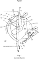
- FIG. 1 the Einkipp ein a large container 10 is shown with sliding cover 12.
- the container is lifted by means of a lift truck 14 and a pivoting drive device 16 and tilted about a pivot axis 18.
- the container is emptied into the pouring opening 20 of a collecting container 22 of a refuse collection vehicle, not shown.
- the swivel drive device 16 and / or the axis 18 of the aforementioned signal generator may be integrated, for example in the form of a rotary encoder for outputting the control signal to a restraint device 24.
- the retaining device 24 comprises a retaining element 26 and a drive device 28.
- the retaining element essentially consists in turn of a stop strip 30 which may be padded to avoid noise and material protection, and a lever arm 32 on which the drive device in the form of a clamping device 34 and a pressure medium cylinder 36 attacks.
- the pressure medium cylinder 36 pivots the retaining element 26 initially from a lower rest position into the upper starting position, in which the retaining element 26 and in particular the stop bar 30 release the pouring opening.
- a guide rail 40 is arranged on a supporting structure or a side wall of the collecting container 22 such that a guide pin 42 on the sliding cover 12 of the container 10 comes into contact with the guide rail 40 during tipping and is guided along it.
- the cover 12 forcibly performs an opening movement.
- the sliding lid during emptying of the container 10 is such opened so that it partially covers the container wall lying in the Einkipphren above and protrudes into the travel of the retaining element 26 or more precisely the stop bar 30. Therefore, in this container 10, the retaining element 26 does not engage with the container wall, but actually with the opened sliding cover 12, causing the problems mentioned at the outset.
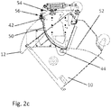
- FIGS. 2a to 2c illustrated in three different tilt positions.
- the large container 10 with sliding cover 12 corresponds to the FIG. 1 ,
- the sliding cover 10 is pivotally suspended on both sides of the container 10 on pin 44.
- the guide rail 50 is arranged on a support structure 54.
- the guide pins 42 move in the combined stroke-tilting movement and the simultaneous positive opening of the lid 12 on the dashed line curve 52.
- the large container 10 is raised and tilted by about 80 ° from the upright position in the direction of the pouring opening, not shown here.
- the guide pin 42 was threaded when tilting the container 10 in the guide rail 50, so that the sliding cover 12 has already been swung in the lower pivot position shown by a small gap.
- the container 10 is further tilted in an angular position of about 100 ° relative to the upright position. Due to the positive guidance by the guide rail 50, the sliding cover 12, driven by the lifting / tilting movement of the container 10, further opened until the container 10 in the Einkipp ein according to Figure 2c has reached an inclination of about 135 ° relative to the vertical and the sliding cover 12 is fully open.
- the Guide pin 42 has reached the upper end point of the curve 52, at which ends approximately the guide rail 50, where the signal generator 56 is located.
- the signal generator 56 is during the basis of FIGS. 2a to 2c triggered Einklippterrorism and outputs a deactivation signal to a controller, not shown, as based on FIG. 3 is explained.
- the guide rail 50 is, as already stated above, arranged laterally of the pouring opening 20 on a support structure 54.
- the support structure in the embodiment shown can in turn be fastened by means of a flange 55 to a side wall of a collecting container, not shown. More precisely, the guide rail 50 is pivotable about a horizontal, oriented perpendicular to its longitudinal axis axis 62 and thus "flexible" in the meaning of the claims attached to the support structure 54 and articulated.
- the articulation point 62 are located substantially at the beginning of the guide rail 50, based on the direction of movement of the guide pin 42 in the Einkippmony the container 10, and the signal generator 56 at the end of the guide rail 50th
- the guide rail 50 has a degree of freedom of movement about the axis 62 and can, at least to a limited extent, execute an evasive movement in the plane of representation when the guide pin 42 contacts or when the guide pin 42 moves along the guide rail 50.
- the signal generator 56 has a sensor 58 on the rear side 53 of the guide rail 50 facing away from the guide side 51 and comes into contact with the guide rail 50 when it makes the deflection movement when it comes into contact with the guide pin 42 or when the guide pin 42 passes.
- the signal generator 56 further has a restoring element 60, which is likewise located on the rear side 53 facing away from the guide side 51 at the upper end of the guide rail 50.
- the return element 60 is in Case shown here, a compression spring, against the restoring force of the guide rail 50 is pressed resiliently in contact with the guide pin 42 in the direction of the sensor 58.
- the guide rail 50 and the return element 60 are in the enlarged section of FIG. 4a shown in the rest position, in which the sensor 58 does not trigger.
- the restoring element 60 is prestressed and the pressure force can be adjusted by the degree of prestressing.
- the Andschreibmoment of the guide pin 42 can be adjusted, in which the sensor 58 is activated.
- the position along the curve 52 can be adjusted, in which the restoring force of the return element 60 is overcome to trigger the sensor 58. This position is in FIG. 4b shown.
- the guide rail 50 can also be resilient in itself and rigidly connected to the support structure 54 in the region of its lower end. This also represents a variant of the "yielding" attachment in the sense of the claims.
- Both the elastic restoring force of the restoring element and that of the resilient guide rail dampens the deflection movement of the guide rail on contact with the guide pin.
- a stop or a separate damper element on the back 53 of the guide rail 50 may be arranged, which limits the deflection movement of the guide rail to a maximum deflection or that absorbs the impact energy of the guide rail in contact with the guide pin and the sensor 58 before too large mechanical Protects load.
- a retaining element 64 in turn essentially consisting of a stop bar 66, which may be padded to avoid noise and material protection, and a lever arm 68 shown.
- the lever arm 68 is pivoted to the support structure 54 about the axis 70.
- opposite end 72 engages in comparison with FIG. 1 alternative drive means 74 in the form of a double-acting pressure medium cylinder 76 at.
- the cylinder 76 is fully retracted and the retaining member 64 is pivoted to a rest position. In operation, the cylinder 76 extends and pivots the retaining member 64 as described above in the overhead start position to release the Ein forö Samuel.
- the cylinder retracts from the starting position by a certain amount.
- a pressure limiter to prevent damage to the container.
Landscapes
- Engineering & Computer Science (AREA)
- Mechanical Engineering (AREA)
- Refuse Receptacles (AREA)
- Closures For Containers (AREA)
Priority Applications (1)
| Application Number | Priority Date | Filing Date | Title |
|---|---|---|---|
| PL17168219T PL3239072T3 (pl) | 2016-04-27 | 2017-04-26 | Urządzenie przytrzymujące pojemnik |
Applications Claiming Priority (1)
| Application Number | Priority Date | Filing Date | Title |
|---|---|---|---|
| DE102016107825.5A DE102016107825A1 (de) | 2016-04-27 | 2016-04-27 | Behälterrückhaltevorrichtung |
Publications (2)
| Publication Number | Publication Date |
|---|---|
| EP3239072A1 EP3239072A1 (de) | 2017-11-01 |
| EP3239072B1 true EP3239072B1 (de) | 2019-04-24 |
Family
ID=58632891
Family Applications (1)
| Application Number | Title | Priority Date | Filing Date |
|---|---|---|---|
| EP17168219.8A Active EP3239072B1 (de) | 2016-04-27 | 2017-04-26 | Behälterrückhaltevorrichtung |
Country Status (6)
| Country | Link |
|---|---|
| EP (1) | EP3239072B1 (pl) |
| DE (1) | DE102016107825A1 (pl) |
| DK (1) | DK3239072T3 (pl) |
| ES (1) | ES2734811T3 (pl) |
| PL (1) | PL3239072T3 (pl) |
| PT (1) | PT3239072T (pl) |
Family Cites Families (2)
| Publication number | Priority date | Publication date | Assignee | Title |
|---|---|---|---|---|
| DE29907954U1 (de) * | 1999-05-04 | 1999-09-02 | OTTO Entsorgungssysteme GmbH, 86179 Augsburg | Hub-Kippvorrichtung zum Entleeren von Müllbehältern |
| DE10221828C1 (de) | 2002-05-10 | 2003-06-05 | Zoeller Kipper | Behälterrückhaltevorrichtung |
-
2016
- 2016-04-27 DE DE102016107825.5A patent/DE102016107825A1/de not_active Ceased
-
2017
- 2017-04-26 DK DK17168219.8T patent/DK3239072T3/da active
- 2017-04-26 EP EP17168219.8A patent/EP3239072B1/de active Active
- 2017-04-26 ES ES17168219T patent/ES2734811T3/es active Active
- 2017-04-26 PL PL17168219T patent/PL3239072T3/pl unknown
- 2017-04-26 PT PT17168219T patent/PT3239072T/pt unknown
Non-Patent Citations (1)
| Title |
|---|
| None * |
Also Published As
| Publication number | Publication date |
|---|---|
| DK3239072T3 (da) | 2019-07-22 |
| DE102016107825A1 (de) | 2017-11-02 |
| EP3239072A1 (de) | 2017-11-01 |
| PT3239072T (pt) | 2019-07-16 |
| ES2734811T3 (es) | 2019-12-12 |
| PL3239072T3 (pl) | 2019-09-30 |
Similar Documents
| Publication | Publication Date | Title |
|---|---|---|
| EP0309703B1 (de) | Schleppfahrzeug für Flugzeuge-Lenkergesteuerte Hubschaufel | |
| DE3732644C1 (de) | Schleppfahrzeug fuer Flugzeuge - Definierte Verzurrkraefte | |
| CH638738A5 (de) | Schaltvorrichtung fuer die senk- und die schwenkschiene an einer faltschachtelpackmaschine. | |
| EP0801013A1 (de) | Abfallsammelbehälter | |
| EP3239072B1 (de) | Behälterrückhaltevorrichtung | |
| EP4313814B1 (de) | Behälterhebe- und entleervorrichtung | |
| EP1068797B1 (de) | Vorrichtung zum Mischen und Austragen von Schüttgut | |
| EP1619143B1 (de) | Verfahren und Vorrichtung zur Absicherung des Arbeitsbereiches von Entleervorrichtungen | |
| DE10221828C1 (de) | Behälterrückhaltevorrichtung | |
| DE2524159A1 (de) | Vorrichtung zum entleeren von mit seitlich vorstehenden tragelementen, beispielsweise tragzapfen, versehenen behaeltern | |
| DE102007019187B3 (de) | Rebenbearbeitungseinrichtung | |
| EP0736465B1 (de) | Hubkipp- oder Kippvorrichtung zum Entleeren von Behältern | |
| DE69801390T2 (de) | Hub-Kippvorrichtung für Behälter und mit einer solchen Vorrichtung ausgestatteter Müllsammelbehälter | |
| EP1044146B1 (de) | Vorrichtung zum entleeren von müllbehältern | |
| EP0686581B1 (de) | Kombinierte Verriegelungs- und Abstützvorrichtung für Müllbehälter | |
| EP3315431A1 (de) | Schütteinrichtung zum entleeren einer mülltonne | |
| DE2043177A1 (de) | Ein einen Behalter tragendes Kraftfahr | |
| DE1245840B (de) | Kippvorrichtung zum Entleeren von Grossraum-Muellbehaeltern in eine Einschuett-vorrichtung an Muellwagen | |
| DE1268539B (de) | Einrichtung zum Entleeren von Muellgefaessen mit rechteckigem Grundriss und zylindrisch gewoelbtem Deckel | |
| EP4647365A1 (de) | Hub-kipp-vorrichtung und verfahren zum betreiben einer hub-kipp-vorrichtung | |
| EP2848853B1 (de) | Vorrichtung zur Arretierung eines verschiebbaren Bauteils | |
| DE102022203949A1 (de) | Sicherheitseinrichtung für einen Anhänger eines fahrerlosen Transportsystems | |
| DE3831796A1 (de) | Hub- und kippvorrichtung zum anbau an muellpressen, muellfahrzeuge u. dgl. | |
| DE2516789A1 (de) | Einrichtung bei muellautos | |
| DE2758583A1 (de) | Hub-kippvorrichtung zum entleeren von behaeltern, insbesondere muellgefaessen in muellsammelbehaelter |
Legal Events
| Date | Code | Title | Description |
|---|---|---|---|
| PUAI | Public reference made under article 153(3) epc to a published international application that has entered the european phase |
Free format text: ORIGINAL CODE: 0009012 |
|
| STAA | Information on the status of an ep patent application or granted ep patent |
Free format text: STATUS: REQUEST FOR EXAMINATION WAS MADE |
|
| 17P | Request for examination filed |
Effective date: 20170426 |
|
| AK | Designated contracting states |
Kind code of ref document: A1 Designated state(s): AL AT BE BG CH CY CZ DE DK EE ES FI FR GB GR HR HU IE IS IT LI LT LU LV MC MK MT NL NO PL PT RO RS SE SI SK SM TR |
|
| AX | Request for extension of the european patent |
Extension state: BA ME |
|
| RIC1 | Information provided on ipc code assigned before grant |
Ipc: B65F 3/02 20060101ALN20181010BHEP Ipc: B65F 3/04 20060101AFI20181010BHEP |
|
| RIC1 | Information provided on ipc code assigned before grant |
Ipc: B65F 3/04 20060101AFI20181018BHEP Ipc: B65F 3/02 20060101ALN20181018BHEP |
|
| GRAP | Despatch of communication of intention to grant a patent |
Free format text: ORIGINAL CODE: EPIDOSNIGR1 |
|
| STAA | Information on the status of an ep patent application or granted ep patent |
Free format text: STATUS: GRANT OF PATENT IS INTENDED |
|
| INTG | Intention to grant announced |
Effective date: 20181126 |
|
| GRAS | Grant fee paid |
Free format text: ORIGINAL CODE: EPIDOSNIGR3 |
|
| GRAA | (expected) grant |
Free format text: ORIGINAL CODE: 0009210 |
|
| STAA | Information on the status of an ep patent application or granted ep patent |
Free format text: STATUS: THE PATENT HAS BEEN GRANTED |
|
| AK | Designated contracting states |
Kind code of ref document: B1 Designated state(s): AL AT BE BG CH CY CZ DE DK EE ES FI FR GB GR HR HU IE IS IT LI LT LU LV MC MK MT NL NO PL PT RO RS SE SI SK SM TR |
|
| REG | Reference to a national code |
Ref country code: GB Ref legal event code: FG4D Free format text: NOT ENGLISH |
|
| REG | Reference to a national code |
Ref country code: CH Ref legal event code: EP |
|
| REG | Reference to a national code |
Ref country code: AT Ref legal event code: REF Ref document number: 1123890 Country of ref document: AT Kind code of ref document: T Effective date: 20190515 Ref country code: IE Ref legal event code: FG4D Free format text: LANGUAGE OF EP DOCUMENT: GERMAN |
|
| REG | Reference to a national code |
Ref country code: DE Ref legal event code: R096 Ref document number: 502017001160 Country of ref document: DE |
|
| REG | Reference to a national code |
Ref country code: PT Ref legal event code: SC4A Ref document number: 3239072 Country of ref document: PT Date of ref document: 20190716 Kind code of ref document: T Free format text: AVAILABILITY OF NATIONAL TRANSLATION Effective date: 20190709 |
|
| REG | Reference to a national code |
Ref country code: DK Ref legal event code: T3 Effective date: 20190718 |
|
| REG | Reference to a national code |
Ref country code: NL Ref legal event code: FP |
|
| REG | Reference to a national code |
Ref country code: LT Ref legal event code: MG4D |
|
| PG25 | Lapsed in a contracting state [announced via postgrant information from national office to epo] |
Ref country code: AL Free format text: LAPSE BECAUSE OF FAILURE TO SUBMIT A TRANSLATION OF THE DESCRIPTION OR TO PAY THE FEE WITHIN THE PRESCRIBED TIME-LIMIT Effective date: 20190424 Ref country code: SE Free format text: LAPSE BECAUSE OF FAILURE TO SUBMIT A TRANSLATION OF THE DESCRIPTION OR TO PAY THE FEE WITHIN THE PRESCRIBED TIME-LIMIT Effective date: 20190424 Ref country code: FI Free format text: LAPSE BECAUSE OF FAILURE TO SUBMIT A TRANSLATION OF THE DESCRIPTION OR TO PAY THE FEE WITHIN THE PRESCRIBED TIME-LIMIT Effective date: 20190424 Ref country code: NO Free format text: LAPSE BECAUSE OF FAILURE TO SUBMIT A TRANSLATION OF THE DESCRIPTION OR TO PAY THE FEE WITHIN THE PRESCRIBED TIME-LIMIT Effective date: 20190724 Ref country code: LT Free format text: LAPSE BECAUSE OF FAILURE TO SUBMIT A TRANSLATION OF THE DESCRIPTION OR TO PAY THE FEE WITHIN THE PRESCRIBED TIME-LIMIT Effective date: 20190424 Ref country code: HR Free format text: LAPSE BECAUSE OF FAILURE TO SUBMIT A TRANSLATION OF THE DESCRIPTION OR TO PAY THE FEE WITHIN THE PRESCRIBED TIME-LIMIT Effective date: 20190424 |
|
| PG25 | Lapsed in a contracting state [announced via postgrant information from national office to epo] |
Ref country code: RS Free format text: LAPSE BECAUSE OF FAILURE TO SUBMIT A TRANSLATION OF THE DESCRIPTION OR TO PAY THE FEE WITHIN THE PRESCRIBED TIME-LIMIT Effective date: 20190424 Ref country code: GR Free format text: LAPSE BECAUSE OF FAILURE TO SUBMIT A TRANSLATION OF THE DESCRIPTION OR TO PAY THE FEE WITHIN THE PRESCRIBED TIME-LIMIT Effective date: 20190725 Ref country code: BG Free format text: LAPSE BECAUSE OF FAILURE TO SUBMIT A TRANSLATION OF THE DESCRIPTION OR TO PAY THE FEE WITHIN THE PRESCRIBED TIME-LIMIT Effective date: 20190724 Ref country code: LV Free format text: LAPSE BECAUSE OF FAILURE TO SUBMIT A TRANSLATION OF THE DESCRIPTION OR TO PAY THE FEE WITHIN THE PRESCRIBED TIME-LIMIT Effective date: 20190424 |
|
| REG | Reference to a national code |
Ref country code: ES Ref legal event code: FG2A Ref document number: 2734811 Country of ref document: ES Kind code of ref document: T3 Effective date: 20191212 |
|
| PG25 | Lapsed in a contracting state [announced via postgrant information from national office to epo] |
Ref country code: IS Free format text: LAPSE BECAUSE OF FAILURE TO SUBMIT A TRANSLATION OF THE DESCRIPTION OR TO PAY THE FEE WITHIN THE PRESCRIBED TIME-LIMIT Effective date: 20190824 Ref country code: LU Free format text: LAPSE BECAUSE OF NON-PAYMENT OF DUE FEES Effective date: 20190426 |
|
| REG | Reference to a national code |
Ref country code: DE Ref legal event code: R097 Ref document number: 502017001160 Country of ref document: DE |
|
| PG25 | Lapsed in a contracting state [announced via postgrant information from national office to epo] |
Ref country code: CZ Free format text: LAPSE BECAUSE OF NON-PAYMENT OF DUE FEES Effective date: 20190426 Ref country code: EE Free format text: LAPSE BECAUSE OF FAILURE TO SUBMIT A TRANSLATION OF THE DESCRIPTION OR TO PAY THE FEE WITHIN THE PRESCRIBED TIME-LIMIT Effective date: 20190424 Ref country code: RO Free format text: LAPSE BECAUSE OF FAILURE TO SUBMIT A TRANSLATION OF THE DESCRIPTION OR TO PAY THE FEE WITHIN THE PRESCRIBED TIME-LIMIT Effective date: 20190424 Ref country code: MC Free format text: LAPSE BECAUSE OF FAILURE TO SUBMIT A TRANSLATION OF THE DESCRIPTION OR TO PAY THE FEE WITHIN THE PRESCRIBED TIME-LIMIT Effective date: 20190424 Ref country code: SK Free format text: LAPSE BECAUSE OF FAILURE TO SUBMIT A TRANSLATION OF THE DESCRIPTION OR TO PAY THE FEE WITHIN THE PRESCRIBED TIME-LIMIT Effective date: 20190424 |
|
| PG25 | Lapsed in a contracting state [announced via postgrant information from national office to epo] |
Ref country code: SM Free format text: LAPSE BECAUSE OF FAILURE TO SUBMIT A TRANSLATION OF THE DESCRIPTION OR TO PAY THE FEE WITHIN THE PRESCRIBED TIME-LIMIT Effective date: 20190424 |
|
| PLBE | No opposition filed within time limit |
Free format text: ORIGINAL CODE: 0009261 |
|
| STAA | Information on the status of an ep patent application or granted ep patent |
Free format text: STATUS: NO OPPOSITION FILED WITHIN TIME LIMIT |
|
| PG25 | Lapsed in a contracting state [announced via postgrant information from national office to epo] |
Ref country code: TR Free format text: LAPSE BECAUSE OF FAILURE TO SUBMIT A TRANSLATION OF THE DESCRIPTION OR TO PAY THE FEE WITHIN THE PRESCRIBED TIME-LIMIT Effective date: 20190424 |
|
| 26N | No opposition filed |
Effective date: 20200127 |
|
| PG25 | Lapsed in a contracting state [announced via postgrant information from national office to epo] |
Ref country code: SI Free format text: LAPSE BECAUSE OF FAILURE TO SUBMIT A TRANSLATION OF THE DESCRIPTION OR TO PAY THE FEE WITHIN THE PRESCRIBED TIME-LIMIT Effective date: 20190424 |
|
| PG25 | Lapsed in a contracting state [announced via postgrant information from national office to epo] |
Ref country code: CY Free format text: LAPSE BECAUSE OF FAILURE TO SUBMIT A TRANSLATION OF THE DESCRIPTION OR TO PAY THE FEE WITHIN THE PRESCRIBED TIME-LIMIT Effective date: 20190424 |
|
| PG25 | Lapsed in a contracting state [announced via postgrant information from national office to epo] |
Ref country code: MT Free format text: LAPSE BECAUSE OF FAILURE TO SUBMIT A TRANSLATION OF THE DESCRIPTION OR TO PAY THE FEE WITHIN THE PRESCRIBED TIME-LIMIT Effective date: 20190424 Ref country code: HU Free format text: LAPSE BECAUSE OF FAILURE TO SUBMIT A TRANSLATION OF THE DESCRIPTION OR TO PAY THE FEE WITHIN THE PRESCRIBED TIME-LIMIT; INVALID AB INITIO Effective date: 20170426 |
|
| REG | Reference to a national code |
Ref country code: DE Ref legal event code: R082 Ref document number: 502017001160 Country of ref document: DE Representative=s name: WSL PATENTANWAELTE PARTNERSCHAFT MBB, DE |
|
| PG25 | Lapsed in a contracting state [announced via postgrant information from national office to epo] |
Ref country code: MK Free format text: LAPSE BECAUSE OF FAILURE TO SUBMIT A TRANSLATION OF THE DESCRIPTION OR TO PAY THE FEE WITHIN THE PRESCRIBED TIME-LIMIT Effective date: 20190424 |
|
| P01 | Opt-out of the competence of the unified patent court (upc) registered |
Effective date: 20230526 |
|
| PGFP | Annual fee paid to national office [announced via postgrant information from national office to epo] |
Ref country code: NL Payment date: 20250422 Year of fee payment: 9 |
|
| PGFP | Annual fee paid to national office [announced via postgrant information from national office to epo] |
Ref country code: PL Payment date: 20250411 Year of fee payment: 9 Ref country code: DE Payment date: 20250417 Year of fee payment: 9 |
|
| PGFP | Annual fee paid to national office [announced via postgrant information from national office to epo] |
Ref country code: ES Payment date: 20250519 Year of fee payment: 9 Ref country code: DK Payment date: 20250423 Year of fee payment: 9 |
|
| PGFP | Annual fee paid to national office [announced via postgrant information from national office to epo] |
Ref country code: BE Payment date: 20250422 Year of fee payment: 9 Ref country code: IT Payment date: 20250430 Year of fee payment: 9 |
|
| PGFP | Annual fee paid to national office [announced via postgrant information from national office to epo] |
Ref country code: PT Payment date: 20250417 Year of fee payment: 9 |
|
| PGFP | Annual fee paid to national office [announced via postgrant information from national office to epo] |
Ref country code: FR Payment date: 20250425 Year of fee payment: 9 |
|
| PGFP | Annual fee paid to national office [announced via postgrant information from national office to epo] |
Ref country code: CH Payment date: 20250501 Year of fee payment: 9 |
|
| PGFP | Annual fee paid to national office [announced via postgrant information from national office to epo] |
Ref country code: AT Payment date: 20250416 Year of fee payment: 9 |
|
| PGFP | Annual fee paid to national office [announced via postgrant information from national office to epo] |
Ref country code: IE Payment date: 20250428 Year of fee payment: 9 |
|
| PGFP | Annual fee paid to national office [announced via postgrant information from national office to epo] |
Ref country code: GB Payment date: 20260324 Year of fee payment: 10 |