EP3239023A1 - Montant et élément formé par profilage pour véhicule - Google Patents
Montant et élément formé par profilage pour véhicule Download PDFInfo
- Publication number
- EP3239023A1 EP3239023A1 EP15873623.1A EP15873623A EP3239023A1 EP 3239023 A1 EP3239023 A1 EP 3239023A1 EP 15873623 A EP15873623 A EP 15873623A EP 3239023 A1 EP3239023 A1 EP 3239023A1
- Authority
- EP
- European Patent Office
- Prior art keywords
- body portion
- connection bonding
- sectional
- closed cross
- pillar
- Prior art date
- Legal status (The legal status is an assumption and is not a legal conclusion. Google has not performed a legal analysis and makes no representation as to the accuracy of the status listed.)
- Granted
Links
- 238000000034 method Methods 0.000 claims abstract description 51
- 229910000831 Steel Inorganic materials 0.000 claims description 49
- 239000010959 steel Substances 0.000 claims description 49
- 230000008569 process Effects 0.000 claims description 29
- 239000000463 material Substances 0.000 claims description 8
- 229910000734 martensite Inorganic materials 0.000 claims description 6
- 230000009977 dual effect Effects 0.000 claims description 4
- 230000009466 transformation Effects 0.000 claims description 4
- 229910000794 TRIP steel Inorganic materials 0.000 claims description 2
- 229910000937 TWIP steel Inorganic materials 0.000 claims description 2
- 238000009751 slip forming Methods 0.000 abstract 2
- 238000004519 manufacturing process Methods 0.000 description 43
- 238000003466 welding Methods 0.000 description 38
- 230000003247 decreasing effect Effects 0.000 description 5
- 229910000797 Ultra-high-strength steel Inorganic materials 0.000 description 4
- 230000009467 reduction Effects 0.000 description 4
- 238000013000 roll bending Methods 0.000 description 4
- 238000005266 casting Methods 0.000 description 2
- 230000008859 change Effects 0.000 description 2
- 238000005516 engineering process Methods 0.000 description 2
- 230000004048 modification Effects 0.000 description 2
- 238000012986 modification Methods 0.000 description 2
- 206010039203 Road traffic accident Diseases 0.000 description 1
- 230000000694 effects Effects 0.000 description 1
- 238000003825 pressing Methods 0.000 description 1
Images


Classifications
-
- B—PERFORMING OPERATIONS; TRANSPORTING
- B62—LAND VEHICLES FOR TRAVELLING OTHERWISE THAN ON RAILS
- B62D—MOTOR VEHICLES; TRAILERS
- B62D25/00—Superstructure or monocoque structure sub-units; Parts or details thereof not otherwise provided for
- B62D25/04—Door pillars ; windshield pillars
-
- B—PERFORMING OPERATIONS; TRANSPORTING
- B21—MECHANICAL METAL-WORKING WITHOUT ESSENTIALLY REMOVING MATERIAL; PUNCHING METAL
- B21B—ROLLING OF METAL
- B21B1/00—Metal-rolling methods or mills for making semi-finished products of solid or profiled cross-section; Sequence of operations in milling trains; Layout of rolling-mill plant, e.g. grouping of stands; Succession of passes or of sectional pass alternations
- B21B1/08—Metal-rolling methods or mills for making semi-finished products of solid or profiled cross-section; Sequence of operations in milling trains; Layout of rolling-mill plant, e.g. grouping of stands; Succession of passes or of sectional pass alternations for rolling structural sections, i.e. work of special cross-section, e.g. angle steel
-
- B—PERFORMING OPERATIONS; TRANSPORTING
- B21—MECHANICAL METAL-WORKING WITHOUT ESSENTIALLY REMOVING MATERIAL; PUNCHING METAL
- B21D—WORKING OR PROCESSING OF SHEET METAL OR METAL TUBES, RODS OR PROFILES WITHOUT ESSENTIALLY REMOVING MATERIAL; PUNCHING METAL
- B21D5/00—Bending sheet metal along straight lines, e.g. to form simple curves
- B21D5/06—Bending sheet metal along straight lines, e.g. to form simple curves by drawing procedure making use of dies or forming-rollers, e.g. making profiles
-
- B—PERFORMING OPERATIONS; TRANSPORTING
- B62—LAND VEHICLES FOR TRAVELLING OTHERWISE THAN ON RAILS
- B62D—MOTOR VEHICLES; TRAILERS
- B62D21/00—Understructures, i.e. chassis frame on which a vehicle body may be mounted
- B62D21/15—Understructures, i.e. chassis frame on which a vehicle body may be mounted having impact absorbing means, e.g. a frame designed to permanently or temporarily change shape or dimension upon impact with another body
- B62D21/157—Understructures, i.e. chassis frame on which a vehicle body may be mounted having impact absorbing means, e.g. a frame designed to permanently or temporarily change shape or dimension upon impact with another body for side impacts
-
- B—PERFORMING OPERATIONS; TRANSPORTING
- B62—LAND VEHICLES FOR TRAVELLING OTHERWISE THAN ON RAILS
- B62D—MOTOR VEHICLES; TRAILERS
- B62D24/00—Connections between vehicle body and vehicle frame
-
- B—PERFORMING OPERATIONS; TRANSPORTING
- B62—LAND VEHICLES FOR TRAVELLING OTHERWISE THAN ON RAILS
- B62D—MOTOR VEHICLES; TRAILERS
- B62D25/00—Superstructure or monocoque structure sub-units; Parts or details thereof not otherwise provided for
- B62D25/06—Fixed roofs
-
- B—PERFORMING OPERATIONS; TRANSPORTING
- B62—LAND VEHICLES FOR TRAVELLING OTHERWISE THAN ON RAILS
- B62D—MOTOR VEHICLES; TRAILERS
- B62D29/00—Superstructures, understructures, or sub-units thereof, characterised by the material thereof
- B62D29/007—Superstructures, understructures, or sub-units thereof, characterised by the material thereof predominantly of special steel or specially treated steel, e.g. stainless steel or locally surface hardened steel
-
- B—PERFORMING OPERATIONS; TRANSPORTING
- B21—MECHANICAL METAL-WORKING WITHOUT ESSENTIALLY REMOVING MATERIAL; PUNCHING METAL
- B21B—ROLLING OF METAL
- B21B2263/00—Shape of product
- B21B2263/02—Profile, e.g. of plate, hot strip, sections
Definitions
- the present disclosure relates to a pillar member and a roll formed member of a vehicle, having relatively high strength at low cost.
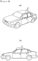
- Pillar members of vehicles are provided as members supporting the roof of a vehicle and as structural members of a vehicle directly affecting the safety of a driver when a vehicle is overturned.
- pillar members may be disposed to be connected to a roof of a vehicle.
- pillar members may be disposed between a windshield and a side window of a vehicle, between a front door and a rear door on a side thereof, between the rear door and a rear window, or the like.
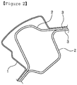
- pillar members having closed cross-sectional portions are formed in such a manner that two press members are cast in an interior of an outer panel forming a vehicle body of a vehicle, and welding flanges formed on opposing end portions of press members are bonded by welding.
- a cross section of pillar members may be significantly large, in order to secure sufficient load bearing performance.
- pillar members of the related art are applied to pillar members formed between the windshield and the side window, driver visibility may be obstructed by pillar members having a cross section, an area of which has been increased, thereby causing traffic accidents.
- giga-class ultra-high strength steel may not be cast using a press casting method of the related art.
- An aspect of the present disclosure may provide a pillar member and a roll formed member having improved load bearing performance and reduced manufacturing expenses by applying a closed cross section structure thereto.
- An aspect of the present disclosure may provide a pillar member and a roll formed member reducing costs by minimizing usage of a steel plate and easily combined with a vehicle frame and a structural member.
- a pillar member of a vehicle comprises a pillar body portion having at least one closed cross-sectional portion and a connection bonding portion disposed on opposing side surfaces of the pillar body portion and combined with a vehicle frame.
- the pillar body portion and the connection bonding portion are consecutively cast.
- the connection bonding portion comprises a first connection bonding portion disposed on one side of the pillar body portion and a second connection bonding portion disposed on the other side of the pillar body portion to oppose the first connection bonding portion.
- the pillar body portion is consecutively cast using a roll forming method in a section between the first connection bonding portion and the second connection bonding portion, thereby forming an even number of closed cross-sectional portions.
- a pillar member of a vehicle comprises a pillar body portion having at least one closed cross-sectional portion and a connection bonding portion disposed on opposing side surfaces of the pillar body portion and combined with a vehicle frame.
- the pillar body portion and the connection bonding portion are consecutively cast.
- the connection bonding portion comprises a first connection bonding portion disposed on one side of the pillar body portion and a second connection bonding portion disposed on the other side of the pillar body portion to oppose the first connection bonding portion.
- the pillar body portion is consecutively cast in a section between the first connection bonding portion and the second connection bonding portion using a roll forming method to comprise a first closed cross-sectional portion and a second closed cross-sectional portion, having a figure-8 type cross section.
- a pillar member of a vehicle comprises a pillar body portion having at least one closed cross-sectional portion and a connection bonding portion disposed on opposing side surfaces of the pillar body portion and combined with a vehicle frame.
- the pillar body portion and the connection bonding portion are consecutively cast.
- the connection bonding portion comprises a first connection bonding portion disposed on one side of the pillar body portion and a second connection bonding portion disposed on the other side of the pillar body portion to oppose the first connection bonding portion.
- the pillar body portion comprises a first body portion panel formed to be extended from the first connection bonding portion, a second body portion panel formed to be extended from the second connection bonding portion, a first closed cross-sectional portion formed between the first body portion panel and the second body portion panel to be connected thereto and consecutively roll formed after the first body portion panel, and a second closed cross-sectional portion having one side connected to the first closed cross-sectional portion and the other side connected to the second connection bonding portion to be consecutively roll formed.
- At least two portions may be lap welded.
- connection bonding portion may be welded to the at least one closed cross-sectional portion disposed closest to the connection bonding portion.
- At least the pillar body portion between the pillar body portion and the connection bonding portion may be configured using a material selected from among martensitic steel, complex phase (CP) steel, dual phase (DP) steel, transformation induced plasticity (TRIP) steel, and twinning induced plasticity (TWIP) steel, having strength of 980 MPa or higher.
- CP complex phase
- DP dual phase
- TWIP transformation induced plasticity
- a pillar member of a vehicle comprises a pillar body portion having at least one closed cross-sectional portion and a connection bonding portion disposed on opposing side surfaces of the pillar body portion and combined with a vehicle frame.
- the pillar body portion and the connection bonding portion are consecutively cast.
- the pillar body portion and the connection bonding portion are consecutively cast using a single roll forming process.
- the pillar member of a vehicle comprises the pillar body portion having a multiple-closed cross-sectional structure including a plurality of closed cross-sectional portions formed to have a triangular cross-sectional shape or a quadrangular cross-sectional shape.
- connection bonding portion may be disposed on a portion of opposing side surfaces of the pillar body portion in a length direction.
- the pillar body portion and the connection bonding portion may be formed at an interface between a windshield and a side window of the vehicle frame in a length direction.
- a roll formed member comprises a roll formed body portion having at least one closed cross-sectional portion and a connection bonding portion disposed on at least one side of the roll formed body portion and combined with a structural member.
- the roll formed body portion and the connection bonding portion are integrally cast using a roll forming method.
- connection bonding portion may include a first connection bonding portion disposed on one side of the roll formed body portion and a second connection bonding portion disposed on the other side of the roll formed body portion to oppose the first connection bonding portion.
- the roll formed body portion may be consecutively cast in a section between the first connection bonding portion and the second connection bonding portion using the roll forming method, in order to form an even number of closed cross-sectional portions.
- the roll formed body portion may be consecutively cast in a section between the first connection bonding portion and the second connection bonding portion using the roll forming method, in order to provide a first closed cross-sectional portion and a second closed cross-sectional portion, having a figure-8 type cross section.
- the roll formed body portion may include a first body portion panel formed to be extended from the first connection bonding portion, a second body portion panel formed to be extended from the second connection bonding portion, a first closed cross-sectional portion connected to the first body portion panel and consecutively roll formed, and a second closed cross-sectional portion having one side connected to the first closed cross-sectional portion and the other side connected to the second body portion panel and consecutively roll formed.
- At least two portions may be lap welded.
- connection bonding portion may be welded to the at least one closed cross-sectional portion disposed closest to the connection bonding portion.
- At least the roll formed body portion between the roll formed body portion and the connection bonding portion may be configured using a material selected from among martensitic steel, complex phase (CP) steel, dual phase (DP) steel, transformation induced plasticity (TRIP) steel, and twinning induced plasticity (TWIP) steel, having strength of 980 MPa or higher.
- CP complex phase
- DP dual phase
- TWIP transformation induced plasticity
- the roll formed body portion and the connection bonding portion may be consecutively cast using a single roll forming process.
- the roll formed member comprises the roll formed body portion having a multiple-closed cross-sectional structure including a plurality of closed cross-sectional portions formed to have a triangular cross-sectional shape or a quadrangular cross-sectional shape.
- connection bonding portion may be formed on a portion of opposing side surfaces of the roll formed body portion in a length direction.
- load bearing performance may be improved by applying a closed cross-sectional structure
- production rates of a pillar member and a roll formed member may be increased by reducing usage of steel and an amount of welding
- manufacturing expenses may be decreased by reducing the usage of steel and the amount of welding.
- manufacturing expenses may be reduced in such a manner that a closed cross-sectional structure is formed to improve load bearing performance of a pillar member and a roll formed member, and a manufacturing process is streamlined, simultaneously, by consecutively casting the pillar member and the roll formed member using a roll forming process.
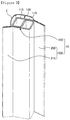
- the pillar member 10 may include a pillar body portion 100 and a connection bonding portion 200.
- the pillar member 10 may comprise the pillar body portion 100 including at least one closed cross-sectional portion 110 and the connection bonding portions 200 disposed on opposing side surfaces of the pillar body portion 100 and combined with a vehicle frame 1.
- the pillar body portion 100 and the connection bonding portion 200 may be consecutively cast.
- the pillar body portion 100 and the connection bonding portion 200, forming the pillar member 10 may be cast to be members having a desired form in such a manner that a steel plate is folded by a roll forming device to have a multistage cross section.
- the pillar body portion 100 and the connection bonding portion 200 may be consecutively cast using a single roll forming process.
- the pillar member 10 and the connection bonding portion 200 may be consecutively cast using the single roll forming process.
- a first connection bonding portion 210, the pillar body portion 100, and a second connection bonding portion 230 are sequentially roll formed, thereby being consecutively cast using the single roll forming process.
- the roll forming process allows for a relatively high degree of size precision and results in substantially no scrapping and wear of a roll, thereby significantly economically manufacturing products having a uniform cross section shape and a relatively long length.
- the roll forming process is a technology in which whenever a set of upper and lower multistage stationary rotating rolls are arranged, and a coil or a material that has been cut passes between each set of rotating rolls, a component is gradually cast to have a form in which a cross section thereof is uniform and a length thereof is relatively long.
- ultra-high strength steel may be cast, the roll forming process is suitable to manufacture a high strength steel component of a vehicle.
- connection bonding portion 200 may include the first connection bonding portion 210 and the second connection bonding portion 230.
- connection bonding portion 200 may include the first connection bonding portion 210 disposed on one side of the pillar body portion 100 and the second connection bonding portion 230 disposed on the other side of the pillar body portion 100 to oppose the first connection bonding portion 210.
- the pillar body portion 100 may be consecutively cast in a section between the first connection bonding portion 210 and the second connection bonding portion 230 using a roll forming method, thereby forming an even number of closed cross-sectional portions 110.
- a closed cross-sectional portion 110 formed in the pillar body portion 100 may be provided as an even number of closed cross-sectional portions, so that the pillar body portion 100 and the connection bonding portion 200 may be integrally cast using the single roll forming process.
- the closed cross-sectional portion 110 may be provided as an even number of closed cross-sectional portions.
- connection bonding portions 200 may not be formed on opposing side surfaces of the pillar body portion 100 to oppose each other, and may be formed in the same direction.
- the closed cross-sectional portion 110 may be provided as an even number of closed cross-sectional portions.
- the pillar member 10 may form the pillar body portion 100 having a closed cross-sectional structure.
- the connection bonding portions 200 opposing each other to be connected to the vehicle frame 1 on opposing side surfaces of the pillar body portion 100 may be cast using the single roll forming process.
- the pillar member 10 may improve load bearing performance by having a closed cross-sectional structure, may increase a production rate of the pillar member 10 by reducing an amount of welding, and may reduce manufacturing expenses of the pillar member 10 due to a reduction in the amount of welding.
- manufacturing expenses may be reduced, and the vehicle frame 1 may be easily combined therewith by minimizing usage of a steel plate used to manufacture the pillar member 10, in such a manner that the closed cross-sectional structure to improve load bearing performance is formed, and the connection bonding portions 200 opposing each other are formed on the opposing side surfaces of the pillar body portion 100.
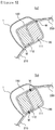
- the pillar body portion 100 may form a figure-8 type cross section in which two closed cross-sectional portions 110 are consecutively formed using the roll forming method.
- the pillar body portion 100 may be consecutively cast in the section between the first connection bonding portion 210 and the second connection bonding portion 230 using the roll forming method, thereby including a first closed cross-sectional portion 111 and a second closed cross-sectional portion 112, having the figure-8 type cross section.
- the first connection bonding portion 210, the pillar body portion 100, and the second connection bonding portion 230, consecutively roll formed the first connection bonding portion 210, the pillar body portion 100, and the second connection body portion may be bonded by welding at two points.
- the pillar body portion 100 having a multiple-closed cross-sectional structure including two or more closed cross-sectional portions 110 may be formed, and the connection bonding portions 200 opposing each other may be formed on the opposing side surfaces of the pillar body portion 100 in such a manner that, in order to bond the first connection bonding portion 210, the pillar body portion 100, and the second connection bonding portion 230, consecutively roll formed, the first connection bonding portion 210, the pillar body portion 100, and the second connection bonding portion 230 are bonded by welding at two points.
- the pillar member 10 may improve load bearing performance by having the multiple-closed cross-sectional structure, may increase a production rate of the pillar member 10 by reducing the amount of welding, and may reduce the manufacturing expenses of the pillar member 10 due to the reduction in the amount of welding.
- the manufacturing expenses may be reduced, and the vehicle frame 1 may be easily combined therewith by minimizing the usage of the steel plate used to manufacture the pillar member 10, in such a manner that the multiple-closed cross-sectional structure to improve load bearing performance is formed, and the connection bonding portions 200 opposing each other are formed on the opposing side surfaces of the pillar body portion 100.
- the pillar body portion 100 may include a first body portion panel 130, a second body portion panel 150, the first closed cross-sectional portion 111, and the second closed cross-sectional portion 112.
- the connection bonding portion 200 may include the first connection bonding portion 210 provided on one side surface of the pillar body portion 100 and the second connection bonding portion 230 provided on the other side surface of the pillar body portion 100.
- the pillar body portion 100 may include the first body portion panel 130 formed to be extended from the first connection bonding portion 210, the second body portion panel 150 formed to be extended from the second connection bonding portion 230, the first closed cross-sectional portion 111 formed between the first body portion panel 130 and the second body portion panel 150 to be connected thereto and consecutively roll formed in the first body portion panel 130, and the second closed cross-sectional portion 112 having one side connected to the first closed cross-sectional portion 111 and the other side connected to the second connection bonding portion 230 and consecutively roll formed.
- the pillar body portion 100 may include the first body portion panel 130 formed to be extended from the first connection bonding portion 210, the second body portion panel 150 formed to be extended from the second connection bonding portion 230, the first closed cross-sectional portion 111 consecutively roll formed to be connected to the first body portion panel 130, and the second closed cross-sectional portion 112 having one side connected to the first closed cross-sectional portion 111 and the other side connected to the second body portion panel 150 and consecutively roll formed.
- a first closed cross-sectional portion 311 and a second closed cross-sectional portion 312 may be formed between a first body portion panel 330 and a second body portion panel 350 to be connected thereto and may be consecutively roll formed.
- the pillar body portion 100 may form a multiple-closed cross-sectional structure including a plurality of closed cross-sectional portions 110 formed to have a triangular cross-sectional shape or a quadrangular cross-sectional shape.
- the first closed cross-sectional portion 111 and the second closed cross-sectional portion 112 may be formed to have a quadrangular cross-sectional shape, corners of which may have a predetermined curvature.
- the first closed cross-sectional portion 111 and the second closed cross-sectional portion 112 may be formed to have a triangular cross-sectional shape, corners of which may have a predetermined curvature.
- a shape of the closed cross-sectional portion 110 is not limited to being triangular or quadrangular.
- the closed cross-sectional portion 110 may have any type of polygonal cross section that may improve load bearing performance of the pillar member 10.
- the first closed cross-sectional portion 111, the second closed cross-sectional portion 112, a third closed cross-sectional portion 113, and a fourth closed cross-sectional portion 114 may be formed to have a quadrangular cross-sectional shape, corners of which may have a predetermined curvature.
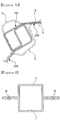
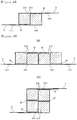
- FIG. 6A two closed cross-sectional portions 110 are formed, while, in FIG. 6B , four closed cross-sectional portions 110 are formed.
- FIGS. 6A and 6B have a difference in load bearing performance of the pillar member 10 and manufacturing expenses depending on usage of steel, or the like.
- FIG. 6A illustrates a form of an optimal pillar member 10 according to an exemplary embodiment securing sufficient load bearing performance by forming a multiple-closed cross-sectional structure including two closed cross-sectional portions 110 and reducing the manufacturing expenses of the pillar member 10 by minimizing the usage of steel and the amount of welding.
- FIG. 6B a multiple-closed cross-sectional structure is formed by forming four closed cross-sectional portions 110, thereby increasing manufacturing expenses, as compared with the case in FIG. 6A , due to an increase in the usage of steel, but load bearing performance is improved.
- FIG. 6B there is substantially no change in an area of cross sections of the pillar member 10 and the vehicle frame 1.
- FIG. 6A and FIG. 6B have no significant difference in terms of securing driver visibility.
- the pillar member 10 illustrated in FIG. 6B may be applied thereto.
- At least two portions among portions of a body portion panel overlapping a member forming the closed cross-sectional portion 110 may be lap welded.
- a portion in which the first body portion panel 130 overlaps a member of the second closed cross-sectional portion 112 and a portion in which the second body portion panel 150 overlaps a member of the first closed cross-sectional portion 111 may be lap welded.
- connection bonding portion 200 may be bonded by welding to the closed cross-sectional portion 110 disposed closest to the connection bonding portion 200.
- the closed cross-sectional portion 110 disposed on a portion in which an interface between the closed cross-sectional portion 110 and the connection bonding portion 200 is formed may be bonded by welding at the interface.
- the first connection bonding portion 210 may be bonded by welding to the first closed cross-sectional portion 111 disposed closest to the first connection bonding portion 210, while the second connection bonding portion 230 may be bonded by welding to the second closed cross-sectional portion 112 disposed closest to the second connection bonding portion 230.
- Structural strength of the pillar member 10 may be secured by forming a welding portion W at only two points. Thus, the amount of welding to form the pillar member 10 may be reduced, thereby reducing the manufacturing expenses of the pillar member 10 and securing sufficient strength thereof.
- the first connection bonding portion 210 may be bonded by welding to the first closed cross-sectional portion 111 disposed closest to the first connection bonding portion 210, while the second connection bonding portion 230 may be bonded by welding to the fourth closed cross-sectional portion 114 disposed closest to the second connection bonding portion 230.
- At least the pillar body portion 100 between the pillar body portion 100 and the connection bonding portion 200 may be configured using a material selected from among martensitic steel, complex phase (CP) steel, dual phase (DP) steel, transformation induced plasticity (TRIP) steel, and twinning induced plasticity (TWIP) steel, having strength of 980 MPa or higher.
- CP complex phase
- DP dual phase
- TWIP transformation induced plasticity
- connection bonding portion 200 may be formed on a portion of opposing side surfaces of the pillar body portion 100 in a length direction.
- connection bonding portion 200 may not be formed on an entirety of sides of the pillar body portion 100 in a length direction thereof, but formed on a portion of sides thereof in the length direction.
- connection bonding portion 200 the usage of steel used to form the connection bonding portion 200 is reduced, and the amount of welding to combine the vehicle frame 1 and a connection bonding portion is minimized, thereby reducing the manufacturing expenses of the pillar member 10 of a vehicle.
- the pillar body portion 100 and the connection bonding portion 200 may be formed at an interface between a windshield and a side window of the vehicle frame 1 in a length direction.
- the pillar body portion 100 and the connection bonding portion 200 may be cast using a roll bending process, thereby forming a curvature in the length direction.
- the pillar body portion 100 and the connection bonding portion 200 are consecutively cast using a single roll forming process to manufacture the pillar member 10, and then the pillar member 10 that has been manufactured may be cast using the roll bending process to have a predetermined curvature in the length direction.
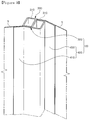
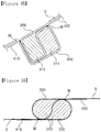
- FIGS. 7A to 7C a pillar member 10 of the related art illustrated in FIG. 2 and a pillar member 10 of the present disclosure illustrated in FIG. 5 will be compared, to be described.
- FIG. 7A is a view contrasting a cross section of the pillar member 10 combined with a vehicle frame 1 of the related art illustrated in FIG. 2 and a cross section of the pillar member 10 combined with a vehicle frame 1 of the present disclosure illustrated in FIG. 5 .
- FIG. 7B is a view contrasting a disposition area of the pillar member 10 combined with the vehicle frame 1 of the related art illustrated in FIG. 2 and a disposition area of the pillar member 10 combined with the vehicle frame 1 of the present disclosure illustrated in FIG. 5 .
- FIG. 7C is a view contrasting the cross section of the pillar member 10 of the vehicle of the related art illustrated in FIG. 2 and the cross section of the pillar member 10 of the vehicle of the present disclosure illustrated in FIG. 5 .
- an area of a cross section thereof is significantly reduced as compared with that of a cross section of the pillar member 10 of the related art illustrated in FIG. 2 , so that the pillar member 10 forming a structural member of a vehicle may secure sufficient load bearing performance, and the area of a cross section of the pillar member 10 is decreased.
- manufacturing expenses of the pillar member 10 may be decreased.
- driver visibility may be sufficiently secured.
- a first area S1 a disposition area, including the pillar member 10 according to an exemplary embodiment illustrated in FIG. 5 and including an outer panel forming the vehicle frame 1 of a vehicle is significantly different from a second area S2, a disposition area, including the pillar member 10 of the related art illustrated in FIG. 2 and an outer panel, in terms of a cross section.
- the roll formed member 20 may include a roll formed body portion 300 and a connection bonding portion 400.
- the roll formed member 20 may include the roll formed body portion 300 forming at least one closed cross-sectional portion 310 and the connection bonding portion 400 disposed on at least one side of the roll formed body portion 300 and combined with a structural member 5.
- the roll formed body portion 300 and the connection bonding portion 400 may be consecutively cast.
- connection bonding portion 400 may be formed on opposing side surfaces of the roll formed body portion 300.
- the structural member 5 may be disposed on the opposing side surfaces of the roll formed body portion 300 by the medium of the connection bonding portion 400.
- connection bonding portion 400 may be formed on a side of the roll formed body portion 300.
- the structural member 5 may only be disposed on the side of the roll formed body portion 300.
- the roll formed body portion 300 and the connection bonding portion 400 forming the roll formed member 20 may be cast to be a member having a desired form in such a manner that a steel plate is folded by a roll forming device to have a multistage cross section.
- the roll formed body portion 300 and the connection bonding portion 400 may be consecutively cast using the single roll forming process.
- the roll formed member 20 and the connection bonding portion 400 may be consecutively cast using the single roll forming process.
- a first connection bonding portion 410, the roll formed body portion 300, and a second connection bonding portion 430 are sequentially roll formed, thereby consecutively being cast using the single roll forming process.
- a roll forming process allows for a relatively high degree of size precision and causes substantially no scrapping and wear of a roll, thereby significantly economically manufacturing products having a uniform cross section shape and having a relatively long length.
- the roll forming process is a technology in which whenever a set of upper and lower multistage stationary rotating rolls is arranged, and a coil or a material that has been cut passes between each set of rotating rolls, a component is gradually cast to have a form in which a cross section thereof is uniform and a length thereof is relatively long.
- the roll forming process is suitable to manufacture a high strength steel component of a vehicle.
- connection bonding portion 400 may include the first connection bonding portion 410 and the second connection bonding portion 430.
- connection bonding portion 400 may include the first connection bonding portion 410 disposed on one side of the roll formed body portion 300 and the second connection bonding portion 430 disposed on the other side of the roll formed body portion 300 to oppose the first connection bonding portion 410.
- the roll formed body portion 300 may be consecutively cast in a section between the first connection bonding portion 410 and the second connection bonding portion 430 using a roll forming method, thereby forming an even number of closed cross-sectional portions 310.
- closed cross-sectional portion 310 may be consecutively formed, while closed cross-sectional portions disposed adjacent to each other may be formed to be in contact with each other.
- the closed cross-sectional portion 310 formed in the roll formed body portion 300 may be provided as an even number of closed cross-sectional portions, so that the roll formed body portion 300 and the connection bonding portion 400 may be integrally cast using the single roll forming process.
- the closed cross-sectional portion 310 may be provided as an even number of closed cross-sectional portions.
- connection bonding portions 400 may not be formed on opposing side surfaces of the roll formed body portion 300 to oppose each other, and may be formed in the same direction.
- the closed cross-sectional portion 310 may be provided as an even number of closed cross-sectional portions.
- the roll formed member 20 may form the roll formed body portion 300 having a closed cross-sectional structure.
- the connection bonding portions 400 opposing each other to be connected to the structural member 5 on opposing side surfaces of the roll formed body portion 300 may be cast using the single roll forming process.
- the roll formed member 20 may improve load bearing performance by having a closed cross-sectional structure, may increase a production rate of the roll formed member 20 by reducing an amount of welding, and may reduce manufacturing expenses of the roll formed member 20 due to a reduction in the amount of welding.
- manufacturing expenses may be reduced, and the structural member 5 may be easily combined therewith by minimizing usage of a steel plate used to manufacture the roll formed member 20, in such a manner that the closed cross-sectional structure to improve load bearing performance is formed, and the connection bonding portions 400 opposing each other are formed on the opposing side surfaces of the roll formed body portion 300.
- the roll formed body portion 300 may have a figure-8 type cross section in which two closed cross-sectional portions 310 are consecutively formed using the roll forming method.
- the roll formed body portion 300 may be consecutively cast in the section between the first connection bonding portion 410 and the second connection bonding portion 430 using the roll forming method, thereby including a first closed cross-sectional portion 311 and a second closed cross-sectional portion 312, having the figure-8 type cross section.
- the first connection bonding portion 410, the roll formed body portion 300, and the second connection bonding portion 430 may be bonded by welding at two points.
- the roll formed body portion 300 having a multiple-closed cross-sectional structure including two or more closed cross-sectional portions 310 may be formed, and the connection bonding portions 400 opposing each other may be formed on the opposing side surfaces of the roll formed body portion 300 in such a manner that, in order to bond the first connection bonding portion 410, the roll formed body portion 300, and the second connection bonding portion 430, consecutively roll formed, the first connection bonding portion 410, the roll formed body portion 300, and the second connection bonding portion 430 are bonded by welding at two points.
- the roll formed member 20 may improve load bearing performance by having the multiple-closed cross-sectional structure, may increase a production rate of the roll formed member 20 by reducing the amount of welding, and may reduce the manufacturing expenses of the roll formed member 20 due to the reduction in the amount of welding.
- the manufacturing expenses may be reduced, and the structural member 5 may be easily combined therewith by minimizing the usage of the steel plate used to manufacture the roll formed member 20, in such a manner that the closed cross-sectional structure to improve load bearing performance is formed, and the connection bonding portions 400 opposing each other are formed on the opposing side surfaces of the roll formed body portion 300.
- the roll formed body portion 300 may include a first body portion panel 330, a second body portion panel 350, the first closed cross-sectional portion 311, and the second closed cross-sectional portion 312.
- the connection bonding portion 400 may include the first connection bonding portion 410 provided on one side surface of the roll formed body portion 300 and the second connection bonding portion 430 provided on the other side surface of the roll formed body portion 300.
- the roll formed body portion 300 may include the first body portion panel 330 formed to be extended from the first connection bonding portion 410, the second body portion panel 350 formed to be extended from the second connection bonding portion 430, the first closed cross-sectional portion 311 connected to the first body portion panel 330 and consecutively roll formed, and the second closed cross-sectional portion 312 having one side connected to the first closed cross-sectional portion 311 and the other side connected to the second body portion panel 350 and consecutively roll formed.
- the first closed cross-sectional portion 311 and the second closed cross-sectional portion 312 may be formed between the first body portion panel 330 and the second body portion panel 350 to be connected thereto and may be consecutively roll formed.
- the roll formed body portion 300 may form the multiple-closed cross-sectional structure including a plurality of closed cross-sectional portions 310 formed to have a triangular cross-sectional shape or a quadrangular cross-sectional shape.
- the first closed cross-sectional portion 311 and the second closed cross-sectional portion 312 may be formed to have a quadrangular cross-sectional shape, corners of which may have a predetermined curvature.
- the first closed cross-sectional portion 311 and the second closed cross-sectional portion 312 may be formed to have a triangular cross-sectional shape, corners of which may have a predetermined curvature.
- a shape of the closed cross-sectional portion 310 is not limited to a triangle and a quadrangle.
- the closed cross-sectional portion 310 may have any type of polygonal cross section that may improve load bearing performance of the roll formed member 20.
- the first closed cross-sectional portion 311, the second closed cross-sectional portion 312, a third closed cross-sectional portion 313, and a fourth closed cross-sectional portion 314 may be formed to have a quadrangular cross-sectional shape, corners of which may have a predetermined curvature.
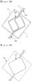
- FIG. 12A two closed cross-sectional portions 310 are formed, while, in FIG. 12B , four closed cross-sectional portions 310 are formed.
- FIG. 12A and FIG. 12B have a difference in load bearing performance of the roll formed member 20 and manufacturing expenses depending on usage of steel, or the like.
- FIG. 12A illustrates a form of an optimum roll formed member 20, according to an exemplary embodiment, securing sufficient load bearing performance by forming the multiple-closed cross-sectional structure including two closed cross-sectional portions 310 and reducing the manufacturing expenses of the roll formed member 20 by minimizing the usage of steel and the amount of welding.
- the multiple-closed cross-sectional structure is formed by forming four closed cross-sectional portions 310, thereby increasing manufacturing expenses, as compared with the case in FIG. 12A , due to an increase in the usage of steel, but load bearing performance is improved.
- the roll formed member 20 illustrated in FIG. 12B may be applied to a connection portion of the structural member 5 requiring sufficient load bearing performance.
- At least nine portions among portions in which a body portion panel overlaps a member forming the closed cross-sectional portion 310 may be lap welded.
- a portion in which the first body portion panel 330 overlaps a member of the second closed cross-sectional portion 312 and a portion in which the second body portion panel 350 overlaps the first closed cross-sectional portion 311 may be lap welded.
- connection bonding portion 400 may be bonded by welding to the closed cross-sectional portion 310 disposed closest to the connection bonding portion 400.
- the closed cross-sectional portion 310 disposed in a portion in which the interface is formed between the connection bonding portion 400 and the closed cross-sectional portion 310 may be bonded by welding at the interface.
- the first connection bonding portion 410 may be bonded by welding to the first closed cross-sectional portion 311 disposed closest to the first connection bonding portion 410, while the second connection bonding portion 430 may be bonded by welding to the second closed cross-sectional portion 312 disposed closest to the second connection bonding portion 430.
- Structural strength of the roll formed member 20 may be secured by forming a welding portion W at only two points. Thus, the amount of welding to form the roll formed member 20 may be reduced, thereby reducing the manufacturing expenses of the roll formed member 20 and securing sufficient strength thereof.
- the first connection bonding portion 410 may be bonded by welding to the first closed cross-sectional portion 311 disposed closest to the first connection bonding portion 410, while the second connection bonding portion 430 may be bonded by welding to the fourth closed cross-sectional portion 314 disposed closest to the second connection bonding portion 430.
- At least the roll formed body portion 300 between the roll formed body portion 300 and the connection bonding portion 400 may be configured using a material selected from among martensitic steel, CP steel, DP steel, TRIP steel, and TWIP steel, having strength of 980 MPa or higher.
- connection bonding portion 400 may be formed on a portion of opposing side surfaces of the roll formed body portion 300 in a length direction.
- connection bonding portion 400 may not be formed in an entirety of side surfaces of the roll formed body portion 300 in a length direction, but formed on a portion thereof in the length direction.
- connection bonding portion 400 the usage of steel used to form the connection bonding portion 400 is reduced, and the amount of welding to combine the structural member 5 and a connection bonding portion is minimized, thereby reducing the manufacturing expenses of the roll formed member 20.
- the roll formed body portion 300 and the connection bonding portion 400 may be formed at an interface of the structural member 5 in a length direction.
- the roll formed body portion 300 and the connection bonding portion 400 may be cast using a roll bending process, thereby forming a curvature in the length direction.
- the roll formed body portion 300 and the connection bonding portion 400 are consecutively cast using the single roll forming process to manufacture the roll formed member 20, and then the roll formed member 20 that has been manufactured may be cast to have the a predetermined curvature in the length direction using the roll bending process.
- FIG. 14A is a view contrasting a cross section of the roll formed member 20 combined with a structural member 5 of the related art illustrated in FIG. 8 and a cross section of the roll formed member 20 combined with a structural member 5 of the present disclosure illustrated in FIG. 11 .
- FIG. 14 is a view contrasting the cross section of the roll formed member 20 of the related art illustrated in FIG. 8 and the cross section of the roll formed member 20 of the present disclosure illustrated in FIG. 11 .
- an area of a cross section thereof is significantly reduced as compared with that of a cross section of the roll formed member 20 of the related art illustrated in FIG. 8 , so that the roll formed member 20 disposed in a bonding portion of the structural member 5 may secure sufficient load bearing performance, and the area of a cross section of the roll formed member 20 is decreased.
- manufacturing expenses of the roll formed member 20 may be decreased.
- a first area S1 a disposition area of the roll formedmember 20 according to an exemplary embodiment illustrated in FIG. 11 is significantly different from a second area S2, a disposition area of the roll formed member 20 of the related art illustrated in FIG. 8 , in terms of a cross section.
- a pillar body portion 300 may include a first body portion panel 330, a second body portion panel 350, a first closed cross-sectional portion 311, and a second closed cross-sectional portion 312.
- the first body portion panel 350 is extended from the second connection bonding portion 430 to be formed, an end portion of the second body portion panel 350 is bent, the second closed cross-sectional portion 312 and the first closed cross section 311 are consecutively formed.
- the first body portion panel 330 is formed after the first closed cross-sectional portion 311 and the second closed cross-sectional portion 312 are formed, and then the first connection bonding portion 410 may be formed after being bent at 90° while being extended in a direction of the first body portion panel 330 along a side surface of the second closed cross-sectional portion 312.
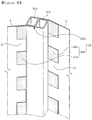
- FIGS. 16 to 19 are views of a roll formed member of the present disclosure having various exemplary embodiments.
- a roll formed body portion 300 may form a multiple-closed cross-sectional structure including a plurality of closed cross-sectional portions 310, at least a portion of corners of which are formed to have an arc form.
- An even number of closed cross-sectional portions 310 are consecutively formed in the roll formed body portion 300, while at least a portion of corners of respective closed cross-sectional portions 310 may be provided to have a curved shape.
- each of the two closed cross-sectional portions 310 may include a figure-8 type cross section having a curved shape.
- the figure-8 type cross section including the two closed cross-sectional portions 310 may be consecutively formed in a horizontal direction, or may be consecutively formed in a vertical direction to form the roll formed body portion 300 as illustrated in FIG. 17B .
- the closed cross-sectional portions 310 may be formed to be overlapped, thereby improving load bearing performance.
- the roll formed body portion 300 may form the multiple-closed cross-sectional structure including a plurality of closed cross-sectional portions 310 formed to have a quadrangular cross-sectional shape.
- an even number of closed cross-sectional portions 310 may be consecutively formed in the roll formed body portion 300. At least a portion of corners of respective closed cross-sectional portions 310 may be provided to have an angular shape.
- respective closed cross-sectional portions 310 may be roll formed to have a quadrangular cross-sectional shape, four corners of which are formed to be angular.
- the figure-8 type cross section including the two closed cross-sectional portions 310 may be consecutively formed in the horizontal direction, or may be consecutively formed in the vertical direction to form the roll formed body portion 300 as illustrated in FIG. 19B .
- the closed cross-sectional portion 310 may have any type of polygonal cross section that may improve load bearing performance of the roll formed member 20.
- the roll formed member 20 may be configured to improve structural performance supporting load in a connection portion of various structural members 5.
- the roll formed member 20 may be applied to various products, such as an impact carrier, a bumper, a frame, a pillar member, or the like, improving structural performance of a vehicle.
Landscapes
- Engineering & Computer Science (AREA)
- Mechanical Engineering (AREA)
- Chemical & Material Sciences (AREA)
- Combustion & Propulsion (AREA)
- Transportation (AREA)
- Architecture (AREA)
- Structural Engineering (AREA)
- Body Structure For Vehicles (AREA)
- Bending Of Plates, Rods, And Pipes (AREA)
Applications Claiming Priority (2)
| Application Number | Priority Date | Filing Date | Title |
|---|---|---|---|
| KR1020140186098A KR101620756B1 (ko) | 2014-12-22 | 2014-12-22 | 차량의 필러부재 |
| PCT/KR2015/014120 WO2016105096A1 (fr) | 2014-12-22 | 2015-12-22 | Montant et élément formé par profilage pour véhicule |
Publications (3)
| Publication Number | Publication Date |
|---|---|
| EP3239023A1 true EP3239023A1 (fr) | 2017-11-01 |
| EP3239023A4 EP3239023A4 (fr) | 2018-01-17 |
| EP3239023B1 EP3239023B1 (fr) | 2021-07-14 |
Family
ID=56023738
Family Applications (1)
| Application Number | Title | Priority Date | Filing Date |
|---|---|---|---|
| EP15873623.1A Active EP3239023B1 (fr) | 2014-12-22 | 2015-12-22 | Montant et élément formé par profilage pour véhicule |
Country Status (6)
| Country | Link |
|---|---|
| US (1) | US10315701B2 (fr) |
| EP (1) | EP3239023B1 (fr) |
| JP (1) | JP6671373B2 (fr) |
| KR (1) | KR101620756B1 (fr) |
| CN (1) | CN107107958B (fr) |
| WO (1) | WO2016105096A1 (fr) |
Families Citing this family (5)
| Publication number | Priority date | Publication date | Assignee | Title |
|---|---|---|---|---|
| DE102015205402B4 (de) * | 2015-03-25 | 2023-06-22 | Bayerische Motoren Werke Aktiengesellschaft | Karosseriestruktur mit einstückigen und als bogenförmige Rohre ausgebildeten B-Säulenverstärkungen, sowie entsprechend ausgebildete B-Säulenverstärkung |
| JP6449799B2 (ja) * | 2016-02-24 | 2019-01-09 | トヨタ自動車株式会社 | 車両用ピラー構造 |
| KR102131535B1 (ko) * | 2018-11-30 | 2020-07-07 | 주식회사 포스코 | 배터리 케이스 |
| MX2022010254A (es) * | 2020-02-21 | 2022-11-08 | Shape Corp | Montaje de viga con formacion de multiples huecos. |
| KR20230029195A (ko) * | 2021-08-24 | 2023-03-03 | 현대자동차주식회사 | 차량용 프런트 필러 |
Family Cites Families (19)
| Publication number | Priority date | Publication date | Assignee | Title |
|---|---|---|---|---|
| JP3196477B2 (ja) | 1993-11-04 | 2001-08-06 | トヨタ自動車株式会社 | 自動車のドア用開口の構造 |
| JP3102539B2 (ja) | 1994-06-30 | 2000-10-23 | 日野自動車株式会社 | ショルダアンカ部のピラー構造 |
| JP3656402B2 (ja) | 1998-04-09 | 2005-06-08 | 日産自動車株式会社 | 押出材製の車体骨格部材 |
| JP3532775B2 (ja) * | 1998-10-15 | 2004-05-31 | 本田技研工業株式会社 | 自動車用押し出し材フレーム結合構造 |
| JP4479243B2 (ja) * | 2004-01-13 | 2010-06-09 | トヨタ自動車株式会社 | フロントピラーの補強構造 |
| FR2901529B1 (fr) | 2006-05-24 | 2008-10-31 | Faurecia Interieur Ind Snc | Traverse de planche de bord de vehicule automobile |
| US7963019B2 (en) * | 2006-08-22 | 2011-06-21 | Ford Global Technologies, Llc | Method of roll-forming an automotive support member |
| JP4752727B2 (ja) | 2006-10-31 | 2011-08-17 | トヨタ自動車株式会社 | 車両のピラー部構造 |
| GB0622027D0 (en) | 2006-11-06 | 2006-12-13 | Ford Global Tech Llc | A reinforcing member for a motor vehicle |
| JP4853315B2 (ja) * | 2007-02-13 | 2012-01-11 | トヨタ自動車株式会社 | 車体骨格構造 |
| JP2008230453A (ja) | 2007-03-22 | 2008-10-02 | Kobe Steel Ltd | センターピラー構造 |
| JP4903077B2 (ja) * | 2007-03-30 | 2012-03-21 | 三菱自動車工業株式会社 | 車両のピラー構造 |
| JP5192991B2 (ja) * | 2008-11-12 | 2013-05-08 | 株式会社神戸製鋼所 | 高強度合金化溶融亜鉛めっき鋼板の製造方法および高強度合金化溶融亜鉛めっき鋼板 |
| JP4947176B2 (ja) | 2010-03-24 | 2012-06-06 | Jfeスチール株式会社 | 超高強度冷延鋼板の製造方法 |
| DE102011052291B4 (de) | 2011-07-29 | 2016-03-10 | Benteler Automobiltechnik Gmbh | Kraftfahrzeugbauteil sowie Verfahren zur Herstellung eines Kraftfahrzeugbauteils |
| KR101353787B1 (ko) * | 2011-12-26 | 2014-01-22 | 주식회사 포스코 | 용접성 및 굽힘가공성이 우수한 초고강도 냉연강판 및 그 제조방법 |
| KR101427957B1 (ko) | 2012-12-13 | 2014-08-11 | 현대자동차 주식회사 | 차량의 필러구조 |
| DE102013003516A1 (de) * | 2013-03-04 | 2014-09-04 | Outokumpu Nirosta Gmbh | Verfahren zur Herstellung eines ultrahochfesten Werkstoffs mit hoher Dehnung |
| US9415810B2 (en) * | 2013-12-31 | 2016-08-16 | Ford Global Technologies, Llc | Vehicle roof structure including a cast node |
-
2014
- 2014-12-22 KR KR1020140186098A patent/KR101620756B1/ko active IP Right Grant
-
2015
- 2015-12-22 EP EP15873623.1A patent/EP3239023B1/fr active Active
- 2015-12-22 WO PCT/KR2015/014120 patent/WO2016105096A1/fr active Application Filing
- 2015-12-22 US US15/536,574 patent/US10315701B2/en active Active
- 2015-12-22 JP JP2017533391A patent/JP6671373B2/ja active Active
- 2015-12-22 CN CN201580069881.5A patent/CN107107958B/zh active Active
Also Published As
| Publication number | Publication date |
|---|---|
| CN107107958B (zh) | 2020-01-10 |
| KR101620756B1 (ko) | 2016-05-13 |
| WO2016105096A1 (fr) | 2016-06-30 |
| JP2018501144A (ja) | 2018-01-18 |
| EP3239023A4 (fr) | 2018-01-17 |
| JP6671373B2 (ja) | 2020-03-25 |
| US10315701B2 (en) | 2019-06-11 |
| CN107107958A (zh) | 2017-08-29 |
| US20170327153A1 (en) | 2017-11-16 |
| EP3239023B1 (fr) | 2021-07-14 |
Similar Documents
| Publication | Publication Date | Title |
|---|---|---|
| EP3239023B1 (fr) | Montant et élément formé par profilage pour véhicule | |
| CN103569206B (zh) | 车辆的车体侧部构造 | |
| CN101817368B (zh) | 车辆侧部车身结构 | |
| CN106458122B (zh) | 车身部件 | |
| JP2016002817A (ja) | 車両用骨格構造 | |
| EP3086890B1 (fr) | Dispositif de fabrication et procede de fabrication d'un composant de carrosserie de vehicule | |
| CN107848475B (zh) | 保险杠加强件和具备该保险杠加强件的车辆 | |
| JP5243864B2 (ja) | 車両用ドアサッシュ | |
| EP2824017A1 (fr) | Structure de montage de rétracteur de ceinture de sécurité | |
| JP6243717B2 (ja) | アンダランプロテクタの構造 | |
| JP2017197191A (ja) | 車両用骨格構造 | |
| KR20160067271A (ko) | 테일러 롤드 블랭크를 이용한 구성부재 및 그 제조방법 | |
| WO2013105439A1 (fr) | Véhicule | |
| EP3501891B1 (fr) | Véhicule porte-conteneurs octogonal télescopique extensible | |
| CN203472995U (zh) | 一种汽车前纵梁中前段结构 | |
| CN108263335B (zh) | 一种安全带卷收器支架总成 | |
| CN105923054A (zh) | 一种天窗总成与车身的连接结构 | |
| JP4904334B2 (ja) | 自動車用エネルギ吸収部材 | |
| JP5568825B2 (ja) | 自動車のカウル部構造 | |
| EP1942045A1 (fr) | Procédé de fabrication d'un pilier pour un véhicule | |
| CN203142796U (zh) | 车身侧围内板总成及汽车车身 | |
| CN201400257Y (zh) | 一种二轮摩托车车架主梁 | |
| WO2016076053A1 (fr) | Élément structurel de véhicule | |
| KR102209407B1 (ko) | 차량 프레임 | |
| KR101767769B1 (ko) | 롤포밍부재 |
Legal Events
| Date | Code | Title | Description |
|---|---|---|---|
| STAA | Information on the status of an ep patent application or granted ep patent |
Free format text: STATUS: THE INTERNATIONAL PUBLICATION HAS BEEN MADE |
|
| PUAI | Public reference made under article 153(3) epc to a published international application that has entered the european phase |
Free format text: ORIGINAL CODE: 0009012 |
|
| STAA | Information on the status of an ep patent application or granted ep patent |
Free format text: STATUS: REQUEST FOR EXAMINATION WAS MADE |
|
| 17P | Request for examination filed |
Effective date: 20170720 |
|
| AK | Designated contracting states |
Kind code of ref document: A1 Designated state(s): AL AT BE BG CH CY CZ DE DK EE ES FI FR GB GR HR HU IE IS IT LI LT LU LV MC MK MT NL NO PL PT RO RS SE SI SK SM TR |
|
| AX | Request for extension of the european patent |
Extension state: BA ME |
|
| A4 | Supplementary search report drawn up and despatched |
Effective date: 20171215 |
|
| RIC1 | Information provided on ipc code assigned before grant |
Ipc: B62D 29/00 20060101ALI20171211BHEP Ipc: B62D 21/15 20060101ALI20171211BHEP Ipc: B62D 25/06 20060101ALI20171211BHEP Ipc: B62D 25/04 20060101AFI20171211BHEP Ipc: B21B 1/08 20060101ALI20171211BHEP |
|
| DAV | Request for validation of the european patent (deleted) | ||
| DAX | Request for extension of the european patent (deleted) | ||
| STAA | Information on the status of an ep patent application or granted ep patent |
Free format text: STATUS: EXAMINATION IS IN PROGRESS |
|
| 17Q | First examination report despatched |
Effective date: 20191007 |
|
| STAA | Information on the status of an ep patent application or granted ep patent |
Free format text: STATUS: EXAMINATION IS IN PROGRESS |
|
| GRAP | Despatch of communication of intention to grant a patent |
Free format text: ORIGINAL CODE: EPIDOSNIGR1 |
|
| STAA | Information on the status of an ep patent application or granted ep patent |
Free format text: STATUS: GRANT OF PATENT IS INTENDED |
|
| INTG | Intention to grant announced |
Effective date: 20210204 |
|
| GRAS | Grant fee paid |
Free format text: ORIGINAL CODE: EPIDOSNIGR3 |
|
| GRAA | (expected) grant |
Free format text: ORIGINAL CODE: 0009210 |
|
| STAA | Information on the status of an ep patent application or granted ep patent |
Free format text: STATUS: THE PATENT HAS BEEN GRANTED |
|
| AK | Designated contracting states |
Kind code of ref document: B1 Designated state(s): AL AT BE BG CH CY CZ DE DK EE ES FI FR GB GR HR HU IE IS IT LI LT LU LV MC MK MT NL NO PL PT RO RS SE SI SK SM TR |
|
| REG | Reference to a national code |
Ref country code: GB Ref legal event code: FG4D |
|
| REG | Reference to a national code |
Ref country code: DE Ref legal event code: R096 Ref document number: 602015071379 Country of ref document: DE |
|
| REG | Reference to a national code |
Ref country code: IE Ref legal event code: FG4D |
|
| REG | Reference to a national code |
Ref country code: AT Ref legal event code: REF Ref document number: 1410423 Country of ref document: AT Kind code of ref document: T Effective date: 20210815 |
|
| REG | Reference to a national code |
Ref country code: LT Ref legal event code: MG9D |
|
| REG | Reference to a national code |
Ref country code: NL Ref legal event code: MP Effective date: 20210714 |
|
| REG | Reference to a national code |
Ref country code: AT Ref legal event code: MK05 Ref document number: 1410423 Country of ref document: AT Kind code of ref document: T Effective date: 20210714 |
|
| PG25 | Lapsed in a contracting state [announced via postgrant information from national office to epo] |
Ref country code: HR Free format text: LAPSE BECAUSE OF FAILURE TO SUBMIT A TRANSLATION OF THE DESCRIPTION OR TO PAY THE FEE WITHIN THE PRESCRIBED TIME-LIMIT Effective date: 20210714 Ref country code: SE Free format text: LAPSE BECAUSE OF FAILURE TO SUBMIT A TRANSLATION OF THE DESCRIPTION OR TO PAY THE FEE WITHIN THE PRESCRIBED TIME-LIMIT Effective date: 20210714 Ref country code: RS Free format text: LAPSE BECAUSE OF FAILURE TO SUBMIT A TRANSLATION OF THE DESCRIPTION OR TO PAY THE FEE WITHIN THE PRESCRIBED TIME-LIMIT Effective date: 20210714 Ref country code: AT Free format text: LAPSE BECAUSE OF FAILURE TO SUBMIT A TRANSLATION OF THE DESCRIPTION OR TO PAY THE FEE WITHIN THE PRESCRIBED TIME-LIMIT Effective date: 20210714 Ref country code: BG Free format text: LAPSE BECAUSE OF FAILURE TO SUBMIT A TRANSLATION OF THE DESCRIPTION OR TO PAY THE FEE WITHIN THE PRESCRIBED TIME-LIMIT Effective date: 20211014 Ref country code: LT Free format text: LAPSE BECAUSE OF FAILURE TO SUBMIT A TRANSLATION OF THE DESCRIPTION OR TO PAY THE FEE WITHIN THE PRESCRIBED TIME-LIMIT Effective date: 20210714 Ref country code: NL Free format text: LAPSE BECAUSE OF FAILURE TO SUBMIT A TRANSLATION OF THE DESCRIPTION OR TO PAY THE FEE WITHIN THE PRESCRIBED TIME-LIMIT Effective date: 20210714 Ref country code: NO Free format text: LAPSE BECAUSE OF FAILURE TO SUBMIT A TRANSLATION OF THE DESCRIPTION OR TO PAY THE FEE WITHIN THE PRESCRIBED TIME-LIMIT Effective date: 20211014 Ref country code: PT Free format text: LAPSE BECAUSE OF FAILURE TO SUBMIT A TRANSLATION OF THE DESCRIPTION OR TO PAY THE FEE WITHIN THE PRESCRIBED TIME-LIMIT Effective date: 20211115 Ref country code: ES Free format text: LAPSE BECAUSE OF FAILURE TO SUBMIT A TRANSLATION OF THE DESCRIPTION OR TO PAY THE FEE WITHIN THE PRESCRIBED TIME-LIMIT Effective date: 20210714 Ref country code: FI Free format text: LAPSE BECAUSE OF FAILURE TO SUBMIT A TRANSLATION OF THE DESCRIPTION OR TO PAY THE FEE WITHIN THE PRESCRIBED TIME-LIMIT Effective date: 20210714 |
|
| PG25 | Lapsed in a contracting state [announced via postgrant information from national office to epo] |
Ref country code: PL Free format text: LAPSE BECAUSE OF FAILURE TO SUBMIT A TRANSLATION OF THE DESCRIPTION OR TO PAY THE FEE WITHIN THE PRESCRIBED TIME-LIMIT Effective date: 20210714 Ref country code: LV Free format text: LAPSE BECAUSE OF FAILURE TO SUBMIT A TRANSLATION OF THE DESCRIPTION OR TO PAY THE FEE WITHIN THE PRESCRIBED TIME-LIMIT Effective date: 20210714 Ref country code: GR Free format text: LAPSE BECAUSE OF FAILURE TO SUBMIT A TRANSLATION OF THE DESCRIPTION OR TO PAY THE FEE WITHIN THE PRESCRIBED TIME-LIMIT Effective date: 20211015 |
|
| REG | Reference to a national code |
Ref country code: DE Ref legal event code: R097 Ref document number: 602015071379 Country of ref document: DE |
|
| PG25 | Lapsed in a contracting state [announced via postgrant information from national office to epo] |
Ref country code: DK Free format text: LAPSE BECAUSE OF FAILURE TO SUBMIT A TRANSLATION OF THE DESCRIPTION OR TO PAY THE FEE WITHIN THE PRESCRIBED TIME-LIMIT Effective date: 20210714 |
|
| PLBE | No opposition filed within time limit |
Free format text: ORIGINAL CODE: 0009261 |
|
| STAA | Information on the status of an ep patent application or granted ep patent |
Free format text: STATUS: NO OPPOSITION FILED WITHIN TIME LIMIT |
|
| PG25 | Lapsed in a contracting state [announced via postgrant information from national office to epo] |
Ref country code: SM Free format text: LAPSE BECAUSE OF FAILURE TO SUBMIT A TRANSLATION OF THE DESCRIPTION OR TO PAY THE FEE WITHIN THE PRESCRIBED TIME-LIMIT Effective date: 20210714 Ref country code: SK Free format text: LAPSE BECAUSE OF FAILURE TO SUBMIT A TRANSLATION OF THE DESCRIPTION OR TO PAY THE FEE WITHIN THE PRESCRIBED TIME-LIMIT Effective date: 20210714 Ref country code: RO Free format text: LAPSE BECAUSE OF FAILURE TO SUBMIT A TRANSLATION OF THE DESCRIPTION OR TO PAY THE FEE WITHIN THE PRESCRIBED TIME-LIMIT Effective date: 20210714 Ref country code: EE Free format text: LAPSE BECAUSE OF FAILURE TO SUBMIT A TRANSLATION OF THE DESCRIPTION OR TO PAY THE FEE WITHIN THE PRESCRIBED TIME-LIMIT Effective date: 20210714 Ref country code: CZ Free format text: LAPSE BECAUSE OF FAILURE TO SUBMIT A TRANSLATION OF THE DESCRIPTION OR TO PAY THE FEE WITHIN THE PRESCRIBED TIME-LIMIT Effective date: 20210714 Ref country code: AL Free format text: LAPSE BECAUSE OF FAILURE TO SUBMIT A TRANSLATION OF THE DESCRIPTION OR TO PAY THE FEE WITHIN THE PRESCRIBED TIME-LIMIT Effective date: 20210714 |
|
| 26N | No opposition filed |
Effective date: 20220419 |
|
| PG25 | Lapsed in a contracting state [announced via postgrant information from national office to epo] |
Ref country code: MC Free format text: LAPSE BECAUSE OF FAILURE TO SUBMIT A TRANSLATION OF THE DESCRIPTION OR TO PAY THE FEE WITHIN THE PRESCRIBED TIME-LIMIT Effective date: 20210714 Ref country code: IT Free format text: LAPSE BECAUSE OF FAILURE TO SUBMIT A TRANSLATION OF THE DESCRIPTION OR TO PAY THE FEE WITHIN THE PRESCRIBED TIME-LIMIT Effective date: 20210714 |
|
| REG | Reference to a national code |
Ref country code: CH Ref legal event code: PL |
|
| GBPC | Gb: european patent ceased through non-payment of renewal fee |
Effective date: 20211222 |
|
| REG | Reference to a national code |
Ref country code: DE Ref legal event code: R081 Ref document number: 602015071379 Country of ref document: DE Owner name: POSCO CO., LTD, POHANG-SI, KR Free format text: FORMER OWNER: POSCO, POHANG-SI, GYEONGSANGBUK-DO, KR Ref country code: DE Ref legal event code: R081 Ref document number: 602015071379 Country of ref document: DE Owner name: POSCO CO., LTD, POHANG- SI, KR Free format text: FORMER OWNER: POSCO, POHANG-SI, GYEONGSANGBUK-DO, KR Ref country code: DE Ref legal event code: R081 Ref document number: 602015071379 Country of ref document: DE Owner name: POSCO HOLDINGS INC., KR Free format text: FORMER OWNER: POSCO, POHANG-SI, GYEONGSANGBUK-DO, KR |
|
| REG | Reference to a national code |
Ref country code: BE Ref legal event code: MM Effective date: 20211231 |
|
| PG25 | Lapsed in a contracting state [announced via postgrant information from national office to epo] |
Ref country code: LU Free format text: LAPSE BECAUSE OF NON-PAYMENT OF DUE FEES Effective date: 20211222 Ref country code: IE Free format text: LAPSE BECAUSE OF NON-PAYMENT OF DUE FEES Effective date: 20211222 Ref country code: GB Free format text: LAPSE BECAUSE OF NON-PAYMENT OF DUE FEES Effective date: 20211222 |
|
| PG25 | Lapsed in a contracting state [announced via postgrant information from national office to epo] |
Ref country code: BE Free format text: LAPSE BECAUSE OF NON-PAYMENT OF DUE FEES Effective date: 20211231 |
|
| PG25 | Lapsed in a contracting state [announced via postgrant information from national office to epo] |
Ref country code: LI Free format text: LAPSE BECAUSE OF NON-PAYMENT OF DUE FEES Effective date: 20211231 Ref country code: CH Free format text: LAPSE BECAUSE OF NON-PAYMENT OF DUE FEES Effective date: 20211231 |
|
| REG | Reference to a national code |
Ref country code: DE Ref legal event code: R081 Ref document number: 602015071379 Country of ref document: DE Owner name: POSCO CO., LTD, POHANG-SI, KR Free format text: FORMER OWNER: POSCO HOLDINGS INC., SEOUL, KR Ref country code: DE Ref legal event code: R081 Ref document number: 602015071379 Country of ref document: DE Owner name: POSCO CO., LTD, POHANG- SI, KR Free format text: FORMER OWNER: POSCO HOLDINGS INC., SEOUL, KR |
|
| PG25 | Lapsed in a contracting state [announced via postgrant information from national office to epo] |
Ref country code: HU Free format text: LAPSE BECAUSE OF FAILURE TO SUBMIT A TRANSLATION OF THE DESCRIPTION OR TO PAY THE FEE WITHIN THE PRESCRIBED TIME-LIMIT; INVALID AB INITIO Effective date: 20151222 |
|
| PG25 | Lapsed in a contracting state [announced via postgrant information from national office to epo] |
Ref country code: CY Free format text: LAPSE BECAUSE OF FAILURE TO SUBMIT A TRANSLATION OF THE DESCRIPTION OR TO PAY THE FEE WITHIN THE PRESCRIBED TIME-LIMIT Effective date: 20210714 |
|
| PGFP | Annual fee paid to national office [announced via postgrant information from national office to epo] |
Ref country code: FR Payment date: 20231222 Year of fee payment: 9 |
|
| PG25 | Lapsed in a contracting state [announced via postgrant information from national office to epo] |
Ref country code: MK Free format text: LAPSE BECAUSE OF FAILURE TO SUBMIT A TRANSLATION OF THE DESCRIPTION OR TO PAY THE FEE WITHIN THE PRESCRIBED TIME-LIMIT Effective date: 20210714 |
|
| PGFP | Annual fee paid to national office [announced via postgrant information from national office to epo] |
Ref country code: DE Payment date: 20231220 Year of fee payment: 9 |