EP3238977A1 - Power supply assembly intended for recharging electric batteries of electric vehicles - Google Patents
Power supply assembly intended for recharging electric batteries of electric vehicles Download PDFInfo
- Publication number
- EP3238977A1 EP3238977A1 EP17165168.0A EP17165168A EP3238977A1 EP 3238977 A1 EP3238977 A1 EP 3238977A1 EP 17165168 A EP17165168 A EP 17165168A EP 3238977 A1 EP3238977 A1 EP 3238977A1
- Authority
- EP
- European Patent Office
- Prior art keywords
- cables
- bar
- cable
- power supply
- supply unit
- Prior art date
- Legal status (The legal status is an assumption and is not a legal conclusion. Google has not performed a legal analysis and makes no representation as to the accuracy of the status listed.)
- Granted
Links
- 230000005540 biological transmission Effects 0.000 claims abstract description 15
- 230000005611 electricity Effects 0.000 claims abstract description 3
- 239000011347 resin Substances 0.000 claims description 6
- 229920005989 resin Polymers 0.000 claims description 6
- 230000007935 neutral effect Effects 0.000 claims description 3
- 239000012777 electrically insulating material Substances 0.000 claims 1
- 239000011810 insulating material Substances 0.000 abstract description 3
- 239000002184 metal Substances 0.000 description 6
- 229910052751 metal Inorganic materials 0.000 description 6
- RYGMFSIKBFXOCR-UHFFFAOYSA-N Copper Chemical compound [Cu] RYGMFSIKBFXOCR-UHFFFAOYSA-N 0.000 description 5
- 238000004519 manufacturing process Methods 0.000 description 5
- 229910052802 copper Inorganic materials 0.000 description 3
- 239000010949 copper Substances 0.000 description 3
- 239000007787 solid Substances 0.000 description 3
- 229920000271 Kevlar® Polymers 0.000 description 2
- 230000016571 aggressive behavior Effects 0.000 description 2
- 238000009413 insulation Methods 0.000 description 2
- 238000002955 isolation Methods 0.000 description 2
- 239000004761 kevlar Substances 0.000 description 2
- 239000000463 material Substances 0.000 description 2
- 238000000465 moulding Methods 0.000 description 2
- 239000004033 plastic Substances 0.000 description 2
- 230000000712 assembly Effects 0.000 description 1
- 238000000429 assembly Methods 0.000 description 1
- 239000004020 conductor Substances 0.000 description 1
- 230000008014 freezing Effects 0.000 description 1
- 238000007710 freezing Methods 0.000 description 1
- 238000003780 insertion Methods 0.000 description 1
- 230000037431 insertion Effects 0.000 description 1
- 238000000034 method Methods 0.000 description 1
- 230000001681 protective effect Effects 0.000 description 1
- 238000011144 upstream manufacturing Methods 0.000 description 1
- XLYOFNOQVPJJNP-UHFFFAOYSA-N water Substances O XLYOFNOQVPJJNP-UHFFFAOYSA-N 0.000 description 1
Images

Classifications
-
- B—PERFORMING OPERATIONS; TRANSPORTING
- B60—VEHICLES IN GENERAL
- B60L—PROPULSION OF ELECTRICALLY-PROPELLED VEHICLES; SUPPLYING ELECTRIC POWER FOR AUXILIARY EQUIPMENT OF ELECTRICALLY-PROPELLED VEHICLES; ELECTRODYNAMIC BRAKE SYSTEMS FOR VEHICLES IN GENERAL; MAGNETIC SUSPENSION OR LEVITATION FOR VEHICLES; MONITORING OPERATING VARIABLES OF ELECTRICALLY-PROPELLED VEHICLES; ELECTRIC SAFETY DEVICES FOR ELECTRICALLY-PROPELLED VEHICLES
- B60L53/00—Methods of charging batteries, specially adapted for electric vehicles; Charging stations or on-board charging equipment therefor; Exchange of energy storage elements in electric vehicles
- B60L53/30—Constructional details of charging stations
- B60L53/31—Charging columns specially adapted for electric vehicles
-
- B—PERFORMING OPERATIONS; TRANSPORTING
- B60—VEHICLES IN GENERAL
- B60L—PROPULSION OF ELECTRICALLY-PROPELLED VEHICLES; SUPPLYING ELECTRIC POWER FOR AUXILIARY EQUIPMENT OF ELECTRICALLY-PROPELLED VEHICLES; ELECTRODYNAMIC BRAKE SYSTEMS FOR VEHICLES IN GENERAL; MAGNETIC SUSPENSION OR LEVITATION FOR VEHICLES; MONITORING OPERATING VARIABLES OF ELECTRICALLY-PROPELLED VEHICLES; ELECTRIC SAFETY DEVICES FOR ELECTRICALLY-PROPELLED VEHICLES
- B60L53/00—Methods of charging batteries, specially adapted for electric vehicles; Charging stations or on-board charging equipment therefor; Exchange of energy storage elements in electric vehicles
- B60L53/30—Constructional details of charging stations
-
- H—ELECTRICITY
- H02—GENERATION; CONVERSION OR DISTRIBUTION OF ELECTRIC POWER
- H02G—INSTALLATION OF ELECTRIC CABLES OR LINES, OR OF COMBINED OPTICAL AND ELECTRIC CABLES OR LINES
- H02G9/00—Installations of electric cables or lines in or on the ground or water
- H02G9/04—Installations of electric cables or lines in or on the ground or water in surface ducts; Ducts or covers therefor
-
- H—ELECTRICITY
- H02—GENERATION; CONVERSION OR DISTRIBUTION OF ELECTRIC POWER
- H02G—INSTALLATION OF ELECTRIC CABLES OR LINES, OR OF COMBINED OPTICAL AND ELECTRIC CABLES OR LINES
- H02G3/00—Installations of electric cables or lines or protective tubing therefor in or on buildings, equivalent structures or vehicles
- H02G3/02—Details
- H02G3/04—Protective tubing or conduits, e.g. cable ladders or cable troughs
- H02G3/0493—Service poles
-
- Y—GENERAL TAGGING OF NEW TECHNOLOGICAL DEVELOPMENTS; GENERAL TAGGING OF CROSS-SECTIONAL TECHNOLOGIES SPANNING OVER SEVERAL SECTIONS OF THE IPC; TECHNICAL SUBJECTS COVERED BY FORMER USPC CROSS-REFERENCE ART COLLECTIONS [XRACs] AND DIGESTS
- Y02—TECHNOLOGIES OR APPLICATIONS FOR MITIGATION OR ADAPTATION AGAINST CLIMATE CHANGE
- Y02T—CLIMATE CHANGE MITIGATION TECHNOLOGIES RELATED TO TRANSPORTATION
- Y02T10/00—Road transport of goods or passengers
- Y02T10/60—Other road transportation technologies with climate change mitigation effect
- Y02T10/70—Energy storage systems for electromobility, e.g. batteries
-
- Y—GENERAL TAGGING OF NEW TECHNOLOGICAL DEVELOPMENTS; GENERAL TAGGING OF CROSS-SECTIONAL TECHNOLOGIES SPANNING OVER SEVERAL SECTIONS OF THE IPC; TECHNICAL SUBJECTS COVERED BY FORMER USPC CROSS-REFERENCE ART COLLECTIONS [XRACs] AND DIGESTS
- Y02—TECHNOLOGIES OR APPLICATIONS FOR MITIGATION OR ADAPTATION AGAINST CLIMATE CHANGE
- Y02T—CLIMATE CHANGE MITIGATION TECHNOLOGIES RELATED TO TRANSPORTATION
- Y02T10/00—Road transport of goods or passengers
- Y02T10/60—Other road transportation technologies with climate change mitigation effect
- Y02T10/7072—Electromobility specific charging systems or methods for batteries, ultracapacitors, supercapacitors or double-layer capacitors
-
- Y—GENERAL TAGGING OF NEW TECHNOLOGICAL DEVELOPMENTS; GENERAL TAGGING OF CROSS-SECTIONAL TECHNOLOGIES SPANNING OVER SEVERAL SECTIONS OF THE IPC; TECHNICAL SUBJECTS COVERED BY FORMER USPC CROSS-REFERENCE ART COLLECTIONS [XRACs] AND DIGESTS
- Y02—TECHNOLOGIES OR APPLICATIONS FOR MITIGATION OR ADAPTATION AGAINST CLIMATE CHANGE
- Y02T—CLIMATE CHANGE MITIGATION TECHNOLOGIES RELATED TO TRANSPORTATION
- Y02T90/00—Enabling technologies or technologies with a potential or indirect contribution to GHG emissions mitigation
- Y02T90/10—Technologies relating to charging of electric vehicles
- Y02T90/12—Electric charging stations
Abstract
L'invention se rapporte à un ensemble d'alimentation (1) destiné à la recharge de batteries électriques de véhicules électriques, comprenant au moins un module (2a, 2b) de transmission d'électricité comportant chacun une barre horizontale (3) constituée d'un matériau isolant électrique, ladite barre (3) étant allongée et traversée longitudinalement par des câbles électriques (5, 6, 7, 8).The invention relates to a power supply unit (1) for recharging electric batteries of electric vehicles, comprising at least one electricity transmission module (2a, 2b) each comprising a horizontal bar (3) consisting of an electrical insulating material, said bar (3) being elongated and traversed longitudinally by electric cables (5, 6, 7, 8).
La principale caractéristique d'un ensemble selon l'invention est que lesdits câbles (5, 6, 7, 8) sont souples et émergent des deux extrémités (16, 17) de la barre (3) en étant repliés vers le haut, et en ce que lesdites parties émergeantes repliées des câbles (5, 6, 7, 8) d'au moins l'une desdites extrémités sont destinées à être directement coiffées par une colonne verticale (9) servant de borne d'alimentation à une batterie de véhicule.

Description
L'invention concerne un ensemble d'alimentation destiné à la recharge de batteries électriques de véhicules électriques. Plus spécifiquement, cet ensemble permet de recharger des batteries électriques placées chacune dans un véhicule dans une position fonctionnelle, lesdits véhicules étant garés devant ledit système.The invention relates to a power supply unit for recharging electric batteries of electric vehicles. More specifically, this set allows recharging electric batteries each placed in a vehicle in a functional position, said vehicles being parked in front of said system.
Un ensemble d'alimentation en électricité de batteries électriques de véhicules est par exemple décrit dans la demande de brevet
Un tel ensemble comprend une pluralité de dispositifs de transmission d'électricité destinés à être posés sur le sol et disposant chacun d'un agencement conducteur et comportant au moins un poteau rigide supportant une borne d'alimentation dotée de connecteurs en cuivre. Un tel ensemble présente plusieurs inconvénients :
- il est cher à produire en raison de son procédé de fabrication. En effet, un tel ensemble doit contenir des barres orthogonales de cuivre, une première couche d'isolation en Kevlar, une deuxième couche d'isolation en PVC, et nécessite une pluralité de fixations de type vis/écrou.
- les barres solides de cuivre ont des longueurs constantes et ne peuvent donc pas s'adapter à n'importe quel type de parking,
- le profil actuel de ce type d'ensemble nécessite un procédé par moulage qui est très complexe,
- la connexion électrique entre deux dispositifs de transmission est compliquée, car elle nécessite une liaison de deux câbles pour chaque phase, qui est longue à réaliser.
- it is expensive to produce because of its manufacturing process. Indeed, such an assembly must contain orthogonal copper bars, a first layer of Kevlar insulation, a second layer of PVC insulation, and requires a plurality of screw / nut type fasteners.
- the solid bars of copper have constant lengths and therefore can not adapt to any type of parking,
- the current profile of this type of assembly requires a molding process which is very complex,
- the electrical connection between two transmission devices is complicated because it requires a connection of two cables for each phase, which is long to achieve.
Un ensemble d'alimentation selon l'invention permet de recharger des batteries de véhicule, tout en s'affranchissant des inconvénients relevés dans l'état de la technique.A power supply unit according to the invention makes it possible to recharge vehicle batteries, while avoiding the disadvantages noted in the state of the art.
L'invention a pour objet un ensemble d'alimentation destiné à la recharge de batteries électriques de véhicules électriques, comprenant au moins un module de transmission d'électricité comportant une barre horizontale constituée d'un matériau isolant électrique, ladite barre étant allongée et traversée longitudinalement par des câbles électriques.The invention relates to a power supply unit for recharging electric batteries of electric vehicles, comprising at least one electricity transmission module comprising a bar horizontal formed of an insulating electrical material, said bar being elongate and longitudinally traversed by electric cables.
La principale caractéristique d'un ensemble selon l'invention est que lesdits câbles sont souples et émergent des deux extrémités de la barre en étant repliés vers le haut, lesdites parties émergeantes repliées des câbles d'au moins l'une desdites extrémités étant destinées à être directement coiffées par une colonne verticale servant de borne d'alimentation à une batterie de véhicule. De cette manière, les poteaux rigides des ensembles d'alimentation existants ont été supprimés, pour ne laisser place qu'à des parties émergeantes de câbles repliées vers le haut. Il n'est donc plus nécessaire de réaliser un moulage de ces poteaux, qui implique un temps de fabrication assez long et donc des coûts supplémentaires. De même, la longueur des parties émergeantes repliées des câbles peut facilement être ajustée à une valeur donnée en sélectionnant la bonne longueur de câble, ce qui n'est pas le cas des poteaux existants, dont la hauteur est fixe. Le terme « replié vers le haut » signifie « vertical à 60° près ». La longueur des parties émergeante repliées des câbles au niveau d'une même extrémité de la barre, peut être identique pour tous les câbles, ou variable selon les configurations rencontrées. D'une façon générale, les parties repliées des câbles sont figées dans une position donnée correspondant à un angle d'inclinaison donné, qui peut être à tout moment modifiée au moyen d'une simple torsion manuelle réalisée sans effort particulier. Préférentiellement, chaque câble possède une double gaine externe isolante. La colonne est avantageusement réalisée en métal, et possède un câble électrique relié électriquement aux parties émergeantes repliées des câbles, situées dans ladite colonne. La colonne peut également être fabriquée en plastique. Puisque les barres sont destinées à être posées sur le sol, le terme « horizontal » signifie « horizontal à plus ou moins 10° près ». Le terme « directement » signifie que les parties émergeantes des câbles sont coiffées par une colonne sans l'insertion d'une quelconque pièce d'interface. La présence de câbles souples en lieu et place des poteaux rigides habituellement utilisés, octroie à l'ensemble d'alimentation selon l'invention un caractère de plus grande souplesse, dans la mesure où la longueur des câbles et donc de leurs parties émergeantes peut être ajustée à tout moment, pour notamment s'adapter à une configuration particulière et/ou à une contrainte inopinée. De plus, de telles ensembles sont plus légers et moins chers, car les poteaux rigides ont été supprimés.The main characteristic of an assembly according to the invention is that said cables are flexible and emerge from both ends of the bar by being folded upwards, said folded emergent parts of the cables of at least one of said ends being intended for be directly capped by a vertical column serving as a power supply terminal to a vehicle battery. In this way, the rigid poles of the existing power supply assemblies have been removed, leaving only the emergent parts of cables folded upwards. It is therefore no longer necessary to perform a molding of these posts, which involves a relatively long manufacturing time and therefore additional costs. Similarly, the length of the folded emergent portions of the cables can easily be adjusted to a given value by selecting the right cable length, which is not the case for existing poles, whose height is fixed. The term "folded up" means "vertical to 60 °". The length of the emergent parts folded cables at the same end of the bar, can be the same for all cables, or variable according to the configurations encountered. In general, the folded portions of the cables are fixed in a given position corresponding to a given angle of inclination, which can be modified at any time by means of a simple manual twisting performed without any particular effort. Preferably, each cable has a double insulating outer sheath. The column is advantageously made of metal, and has an electric cable electrically connected to the emerging parts folded cables, located in said column. The column can also be made of plastic. Since the bars are intended to be placed on the ground, the term "horizontal" means "horizontal within plus or minus 10 degrees". The term "directly" means that the emergent parts of the cables are capped by a column without the insertion of any interface piece. The presence of flexible cables instead of rigid poles usually used, gives the power supply unit according to the invention a character of greater flexibility, insofar as the The length of the cables and therefore their emergent parts can be adjusted at any time, in particular to adapt to a particular configuration and / or an unexpected constraint. In addition, such sets are lighter and cheaper because the rigid posts have been removed.
Avantageusement, un ensemble d'alimentation selon l'invention comporte quatre câbles, dont un câble neutre et trois câbles de phase.Advantageously, a power supply unit according to the invention comprises four cables, including a neutral cable and three phase cables.
De façon préférentielle, les câbles sont alignés dans un plan horizontal au sein de chaque barre. De cette manière, les barres peuvent être conçues avec une faible épaisseur. Le plan d'alignement des câbles dans la barre est parallèle au plan de ladite barre.Preferably, the cables are aligned in a horizontal plane within each bar. In this way, the bars can be designed with a small thickness. The alignment plane of the cables in the bar is parallel to the plane of said bar.
De façon avantageuse, la barre est réalisée en résine et possède une tôle de protection et de mise à la terre enfouie dans ladite résine. Le terme « enfouie » signifie que la tôle n'est pas visible, sauf si la barre est transparente. Cette tôle constitue une protection vis-à-vis des câbles traversant la barre, contre des agressions externes, comme par exemple des coups de pioche.Advantageously, the bar is made of resin and has a protective and grounding plate buried in said resin. The term "buried" means that the sheet is not visible unless the bar is transparent. This sheet is a protection vis-à-vis the cables crossing the bar against external aggression, such as picks.
Avantageusement, la tôle est plane et s'étend selon un axe longitudinal de la barre, ladite tôle présentant deux bords longitudinaux repliés et les câbles étant placés entre lesdits deux bords repliés.Advantageously, the sheet is flat and extends along a longitudinal axis of the bar, said sheet having two folded longitudinal edges and the cables being placed between said two folded edges.
Préférentiellement, la longueur de la partie émergeante des câbles au niveau d'une même extrémité de la barre est différente pour chaque câble. De cette manière, les câble traversant une même barre, possède chacun une partie émergeante de longueur différente.Preferably, the length of the emerging part of the cables at the same end of the bar is different for each cable. In this way, the cables passing through the same bar, each has an emerging portion of different length.
De façon avantageuse, l'extrémité de la partie émergeante de chaque câble se termine par une patte conductrice plane et ajourée. De cette manière, chaque patte conductrice ajourée joue le rôle d'un connecteur électrique permettant à chaque câble d'être connectée à un autre élément conducteur, pouvant par exemple être un autre câble électrique. Le fait que chaque patte soit ajourée permet de fixer ladite patte à l'autre élément conducteur au moyen d'une vis. Préférentiellement, les pattes sont en métal. De façon avantageuse, le métal des pattes est le même que celui du câble auquel elles sont rattachées.Advantageously, the end of the emerging portion of each cable ends with a flat and perforated conductive tab. In this way, each perforated lead tab plays the role of an electrical connector allowing each cable to be connected to another conductive element, which may for example be another electrical cable. The fact that each tab is openwork allows to fix said tab to the other conductive element to by means of a screw. Preferably, the legs are made of metal. Advantageously, the metal of the legs is the same as that of the cable to which they are attached.
Avantageusement, chaque câble possède une double gaine externe isolante.Advantageously, each cable has a double insulating outer sheath.
De façon préférentielle, un ensemble d'alimentation selon l'invention comprend au moins deux modules successifs de sorte que les deux barres horizontales desdits modules soient en continuité l'une de l'autre, les parties émergeantes des câbles des deux extrémités desdites barres les plus proches étant connectées électriquement, cette zone de connexion étant destinée à être coiffée par une colonne verticale servant de borne d'alimentation à une batterie de véhicule. Puisque les parties émergeantes des câbles sont repliées vers le haut, la connexion électrique entre les câbles des deux barres s'effectue au-dessus desdites barres. Avantageusement, les deux barres sont parfaitement alignées le long du même axe. Il est également possible que les deux barres soient légèrement inclinées l'une par rapport à l'autre, d'un angle maximal de 15°.Preferably, a power supply unit according to the invention comprises at least two successive modules so that the two horizontal bars of said modules are in continuity with one another, the emerging parts of the cables of the two ends of said bars being closer being electrically connected, this connection area being intended to be capped by a vertical column serving as a power supply terminal to a vehicle battery. Since the emergent parts of the cables are folded upwards, the electrical connection between the cables of the two bars is carried out above said bars. Advantageously, the two bars are perfectly aligned along the same axis. It is also possible that the two bars are slightly inclined relative to each other, at a maximum angle of 15 °.
Préférentiellement, une partie émergeante d'un câble d'une barre est connectée à la partie émergeante du câble de l'autre barre lui faisant face. Ainsi, les câbles ne subissent aucune déformation ou torsion pour venir se connecter à l'autre câble, permettant de réaliser une connexion électrique sans contrainte, et donc sans risque d'être défaite sous le moindre effort.Preferably, an emerging part of a cable of a bar is connected to the emerging part of the cable of the other bar facing it. Thus, the cables do not undergo any deformation or torsion to come connect to the other cable, to make an electrical connection without stress, and therefore without risk of being defeated under the slightest effort.
De façon avantageuse, chaque câble peut être librement déplacé en translation dans une barre horizontale, de manière à pouvoir faire varier la longueur de sa partie émergeante. En effet, les câbles sont placés dans des rainures ou gorges longitudinales d'une barre, si bien qu'ils peuvent être déplacés aisément le long desdites rainures et/ou gorges pour obtenir des parties émergeantes de câbles de longueur souhaitée.Advantageously, each cable can be freely moved in translation in a horizontal bar, so as to vary the length of its emerging part. Indeed, the cables are placed in grooves or longitudinal grooves of a bar, so that they can be moved easily along said grooves and / or grooves to obtain emerging parts of cables of desired length.
Un ensemble d'alimentation selon l'invention présente l'avantage d'être modulable, dans la mesure où la longueur des parties émergeantes repliées des câbles est variable, et peut donc s'adapter à une multiplicité de bornes d'alimentation pour alimenter en courant des batteries électriques de tout type de véhicule. Il a de plus l'avantage d'être facile et rapide à fabriquer, puisqu'il ne nécessite pas l'élaboration de poteaux rigides verticaux, qui engendre un temps de fabrication supplémentaire et donc des coûts supplémentaires.A feed assembly according to the invention has the advantage of being flexible, insofar as the length of the emerging parts folded cables is variable, and can therefore adapt to a multiplicity of power supply terminals for powering electric batteries of any type of vehicle. It also has the advantage of being easy and quick to manufacture, since it does not require the development of vertical rigid columns, which generates additional manufacturing time and therefore additional costs.
On donne, ci-après, une description détaillée d'un mode de réalisation préféré d'un ensemble d'alimentation selon l'invention, en se référant aux figures suivantes :
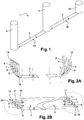
- La
figure 1 est une vue en perspective d'un ensemble selon l'invention montrant des bornes d'alimentation, - La figue 2A est une vue simplifiée de coté d'un module de transmission d'électricité d'un ensemble d'alimentation selon l'invention,
- La
figure 2B est une vue du dessus du module de lafigure 2A , - La
figure 3 est une vue en perspective agrandie d'une extrémité d'un module de transmission d'électricité d'un ensemble d'alimentation selon l'invention, - La
figure 4 est une vue en coupe transversale d'une barre d'un module de transmission d'électricité d'un ensemble d'alimentation selon l'invention, - La
figure 5 est une vue en perspective d'une connexion électrique entre deux modules de transmission d'électricité d'un ensemble d'alimentation selon l'invention.
- The
figure 1 is a perspective view of an assembly according to the invention showing power supply terminals, - FIG. 2A is a simplified side view of a power transmission module of a power supply unit according to the invention,
- The
Figure 2B is a view from above of the module of theFigure 2A , - The
figure 3 is an enlarged perspective view of an end of a power transmission module of a power supply assembly according to the invention, - The
figure 4 is a cross-sectional view of a bar of a power transmission module of a power supply unit according to the invention, - The
figure 5 is a perspective view of an electrical connection between two power transmission modules of a power supply unit according to the invention.
En se référant à la
Les deux modules 2a, 2b sont connectés électriquement au niveau de l'une desdites colonnes verticales 9. Chaque colonne 9 est préférentiellement réalisée en métal ou en plastique solide.The two
En se référant aux
En se référant à la
En se référant aux
Les deux modules 2a, 2b d'un ensemble 1 d'alimentation selon l'invention sont alignés et à proximité l'un de l'autre. Autrement dit, les deux barres 3 des deux modules 2a, 2b sont parfaitement alignées et dans le prolongement l'une de l'autre. Elles ne sont séparées que par quelques centimètres.The two
En se référant à la
Claims (11)
Applications Claiming Priority (1)
| Application Number | Priority Date | Filing Date | Title |
|---|---|---|---|
| FR1653634A FR3050406B1 (en) | 2016-04-25 | 2016-04-25 | POWER SUPPLY ASSEMBLY FOR RECHARGING ELECTRIC BATTERIES OF ELECTRIC VEHICLES |
Publications (2)
| Publication Number | Publication Date |
|---|---|
| EP3238977A1 true EP3238977A1 (en) | 2017-11-01 |
| EP3238977B1 EP3238977B1 (en) | 2023-06-14 |
Family
ID=56101731
Family Applications (1)
| Application Number | Title | Priority Date | Filing Date |
|---|---|---|---|
| EP17165168.0A Active EP3238977B1 (en) | 2016-04-25 | 2017-04-06 | Power supply assembly intended for recharging electric batteries of electric vehicles |
Country Status (2)
| Country | Link |
|---|---|
| EP (1) | EP3238977B1 (en) |
| FR (1) | FR3050406B1 (en) |
Cited By (2)
| Publication number | Priority date | Publication date | Assignee | Title |
|---|---|---|---|---|
| DE102016225134A1 (en) * | 2016-12-15 | 2018-06-21 | Audi Ag | Charging arrangement for supplying an electrical consumer and system |
| CN112078408A (en) * | 2020-09-24 | 2020-12-15 | 广州奕极机电科技有限公司 | Movable electric automobile fills electric pile for new forms of energy electric automobile |
Citations (7)
| Publication number | Priority date | Publication date | Assignee | Title |
|---|---|---|---|---|
| FR321764A (en) * | 1902-06-06 | 1903-01-19 | Pradier Marcel | Cable ducts for electrical conductors and pipes |
| US6081205A (en) * | 1992-05-19 | 2000-06-27 | Williams; Douglas J. | Electronic parking meter and electric automobile recharging station |
| WO2010114455A1 (en) * | 2009-04-02 | 2010-10-07 | Hm Power Ab | Power outlet |
| US20120229085A1 (en) * | 2011-03-07 | 2012-09-13 | Lau David M K | System for charging electric vehicle batteries from street lights and parking meters |
| EP2792536A1 (en) * | 2013-04-16 | 2014-10-22 | Bluecarsharing | Self-supporting structure forming a mounting for a charging station and charging station |
| WO2014191644A1 (en) | 2013-05-31 | 2014-12-04 | Nexans | Power supply assembly intended to recharge electric batteries for electric motor vehicles |
| US20150111423A1 (en) * | 2013-10-21 | 2015-04-23 | A.C. Dandy Products Ltd. | Protective apparatus for outdoor electrical outlets |
Family Cites Families (2)
| Publication number | Priority date | Publication date | Assignee | Title |
|---|---|---|---|---|
| US4165592A (en) * | 1978-01-24 | 1979-08-28 | Blankenship Roy L | Cable directing apparatus |
| GB2483064A (en) * | 2010-08-24 | 2012-02-29 | J F Plastics Ltd | Cable conduit |
-
2016
- 2016-04-25 FR FR1653634A patent/FR3050406B1/en active Active
-
2017
- 2017-04-06 EP EP17165168.0A patent/EP3238977B1/en active Active
Patent Citations (7)
| Publication number | Priority date | Publication date | Assignee | Title |
|---|---|---|---|---|
| FR321764A (en) * | 1902-06-06 | 1903-01-19 | Pradier Marcel | Cable ducts for electrical conductors and pipes |
| US6081205A (en) * | 1992-05-19 | 2000-06-27 | Williams; Douglas J. | Electronic parking meter and electric automobile recharging station |
| WO2010114455A1 (en) * | 2009-04-02 | 2010-10-07 | Hm Power Ab | Power outlet |
| US20120229085A1 (en) * | 2011-03-07 | 2012-09-13 | Lau David M K | System for charging electric vehicle batteries from street lights and parking meters |
| EP2792536A1 (en) * | 2013-04-16 | 2014-10-22 | Bluecarsharing | Self-supporting structure forming a mounting for a charging station and charging station |
| WO2014191644A1 (en) | 2013-05-31 | 2014-12-04 | Nexans | Power supply assembly intended to recharge electric batteries for electric motor vehicles |
| US20150111423A1 (en) * | 2013-10-21 | 2015-04-23 | A.C. Dandy Products Ltd. | Protective apparatus for outdoor electrical outlets |
Cited By (3)
| Publication number | Priority date | Publication date | Assignee | Title |
|---|---|---|---|---|
| DE102016225134A1 (en) * | 2016-12-15 | 2018-06-21 | Audi Ag | Charging arrangement for supplying an electrical consumer and system |
| CN112078408A (en) * | 2020-09-24 | 2020-12-15 | 广州奕极机电科技有限公司 | Movable electric automobile fills electric pile for new forms of energy electric automobile |
| CN112078408B (en) * | 2020-09-24 | 2021-12-10 | 深圳百客新能源有限公司 | Movable electric automobile fills electric pile for new forms of energy electric automobile |
Also Published As
| Publication number | Publication date |
|---|---|
| FR3050406A1 (en) | 2017-10-27 |
| EP3238977B1 (en) | 2023-06-14 |
| FR3050406B1 (en) | 2018-04-27 |
Similar Documents
| Publication | Publication Date | Title |
|---|---|---|
| EP0330525B1 (en) | Prefabricated electric conduit, adaptable to several rated currents, of the type comprising a flat, channelled insulator support for conductor rails | |
| FR2749441A1 (en) | FEMALE ELECTRIC CONTACT TERMINAL WITH CONTROLLED CONTACT PRESSURE | |
| FR2749442A1 (en) | FEMALE ELECTRIC CONTACT TERMINAL WITH REINFORCED STRUCTURE | |
| FR2941565A1 (en) | PHOTOVOLTAIC ENERGY RECOVERY UNIT AND PHOTOVOLTAIC ASSEMBLY COMPRISING SUCH A UNIT. | |
| EP3238977B1 (en) | Power supply assembly intended for recharging electric batteries of electric vehicles | |
| FR2749443A1 (en) | FEMALE ELECTRIC CONTACT TERMINAL WITH REINFORCED TRANSITION AREA | |
| CA2871141A1 (en) | Current return connecting loom and method for mounting on a composite fuselage frame | |
| EP2249442A1 (en) | Retaining profile for an electrical appliance and installation having this retaining profile | |
| FR2504315A1 (en) | CONNECTING ELEMENT AND CONNECTING DEVICE COMPRISING SUCH ELEMENTS | |
| EP3005507B1 (en) | Power supply assembly intended to recharge electric batteries for electric motor vehicles | |
| FR3029361A1 (en) | ELECTRICAL CONNECTION DEVICE | |
| WO2013088052A1 (en) | Equipotential connection system for panel | |
| EP3089295B1 (en) | Electrical interconnection device for an equipotential connection between a cable tray piece and an electrical cable piece. | |
| EP2383849B1 (en) | Vertical electrical connecting device | |
| LU83379A1 (en) | ELECTRICAL CONNECTION DEVICE, PARTICULARLY FOR OFFICE FURNITURE | |
| EP2662931B1 (en) | Connection tip for insulated power-supply cable and method for manufacturing said connection tip | |
| EP3997759B1 (en) | Connection device for grounding an electrical apparatus and/or creating an equipotential link between conductive elements | |
| FR2626723A1 (en) | DEFORMABLE DEVICE FOR CONNECTING ELECTRICAL POWER DISTRIBUTION CONDUITS | |
| EP3633794A1 (en) | Connector | |
| EP0335756B1 (en) | Joining device for two electrical conduit elements put end to end | |
| EP3336967A1 (en) | Electrical connection element | |
| FR2953073A3 (en) | DEVICE FOR ELECTRICALLY CONNECTING AT LEAST TWO ELECTRIC EQUIPMENTS INSTALLED ONE ABOVE THE OTHER IN AN ELECTRICAL DISTRIBUTION CABINET | |
| EP1065749A1 (en) | Connection accessory for electrical apparatus, in particular for modular electrical apparatus | |
| FR2963986A1 (en) | Roof covering device i.e. photovoltaic panel, for capturing solar energy and generating electricity, has electrical connector connected to positive cable and negative cable, and ground wire connected to photovoltaic module | |
| FR3116939A1 (en) | FUSE BOX FOR MOTOR VEHICLE BATTERY |
Legal Events
| Date | Code | Title | Description |
|---|---|---|---|
| PUAI | Public reference made under article 153(3) epc to a published international application that has entered the european phase |
Free format text: ORIGINAL CODE: 0009012 |
|
| STAA | Information on the status of an ep patent application or granted ep patent |
Free format text: STATUS: THE APPLICATION HAS BEEN PUBLISHED |
|
| AK | Designated contracting states |
Kind code of ref document: A1 Designated state(s): AL AT BE BG CH CY CZ DE DK EE ES FI FR GB GR HR HU IE IS IT LI LT LU LV MC MK MT NL NO PL PT RO RS SE SI SK SM TR |
|
| AX | Request for extension of the european patent |
Extension state: BA ME |
|
| STAA | Information on the status of an ep patent application or granted ep patent |
Free format text: STATUS: REQUEST FOR EXAMINATION WAS MADE |
|
| 17P | Request for examination filed |
Effective date: 20180411 |
|
| RBV | Designated contracting states (corrected) |
Designated state(s): AL AT BE BG CH CY CZ DE DK EE ES FI FR GB GR HR HU IE IS IT LI LT LU LV MC MK MT NL NO PL PT RO RS SE SI SK SM TR |
|
| STAA | Information on the status of an ep patent application or granted ep patent |
Free format text: STATUS: EXAMINATION IS IN PROGRESS |
|
| 17Q | First examination report despatched |
Effective date: 20200827 |
|
| STAA | Information on the status of an ep patent application or granted ep patent |
Free format text: STATUS: EXAMINATION IS IN PROGRESS |
|
| STAA | Information on the status of an ep patent application or granted ep patent |
Free format text: STATUS: EXAMINATION IS IN PROGRESS |
|
| REG | Reference to a national code |
Ref country code: DE Ref legal event code: R079 Ref document number: 602017070143 Country of ref document: DE Free format text: PREVIOUS MAIN CLASS: B60L0011180000 Ipc: B60L0053300000 |
|
| RIC1 | Information provided on ipc code assigned before grant |
Ipc: B60L 53/30 20190101AFI20220921BHEP |
|
| GRAP | Despatch of communication of intention to grant a patent |
Free format text: ORIGINAL CODE: EPIDOSNIGR1 |
|
| STAA | Information on the status of an ep patent application or granted ep patent |
Free format text: STATUS: GRANT OF PATENT IS INTENDED |
|
| INTG | Intention to grant announced |
Effective date: 20230105 |
|
| GRAS | Grant fee paid |
Free format text: ORIGINAL CODE: EPIDOSNIGR3 |
|
| GRAA | (expected) grant |
Free format text: ORIGINAL CODE: 0009210 |
|
| STAA | Information on the status of an ep patent application or granted ep patent |
Free format text: STATUS: THE PATENT HAS BEEN GRANTED |
|
| AK | Designated contracting states |
Kind code of ref document: B1 Designated state(s): AL AT BE BG CH CY CZ DE DK EE ES FI FR GB GR HR HU IE IS IT LI LT LU LV MC MK MT NL NO PL PT RO RS SE SI SK SM TR |
|
| REG | Reference to a national code |
Ref country code: CH Ref legal event code: EP |
|
| REG | Reference to a national code |
Ref country code: DE Ref legal event code: R096 Ref document number: 602017070143 Country of ref document: DE |
|
| REG | Reference to a national code |
Ref country code: AT Ref legal event code: REF Ref document number: 1579009 Country of ref document: AT Kind code of ref document: T Effective date: 20230715 |
|
| REG | Reference to a national code |
Ref country code: LT Ref legal event code: MG9D |
|
| REG | Reference to a national code |
Ref country code: NL Ref legal event code: MP Effective date: 20230614 |
|
| PG25 | Lapsed in a contracting state [announced via postgrant information from national office to epo] |
Ref country code: SE Free format text: LAPSE BECAUSE OF FAILURE TO SUBMIT A TRANSLATION OF THE DESCRIPTION OR TO PAY THE FEE WITHIN THE PRESCRIBED TIME-LIMIT Effective date: 20230614 Ref country code: NO Free format text: LAPSE BECAUSE OF FAILURE TO SUBMIT A TRANSLATION OF THE DESCRIPTION OR TO PAY THE FEE WITHIN THE PRESCRIBED TIME-LIMIT Effective date: 20230914 Ref country code: ES Free format text: LAPSE BECAUSE OF FAILURE TO SUBMIT A TRANSLATION OF THE DESCRIPTION OR TO PAY THE FEE WITHIN THE PRESCRIBED TIME-LIMIT Effective date: 20230614 |
|
| REG | Reference to a national code |
Ref country code: AT Ref legal event code: MK05 Ref document number: 1579009 Country of ref document: AT Kind code of ref document: T Effective date: 20230614 |
|
| PG25 | Lapsed in a contracting state [announced via postgrant information from national office to epo] |
Ref country code: RS Free format text: LAPSE BECAUSE OF FAILURE TO SUBMIT A TRANSLATION OF THE DESCRIPTION OR TO PAY THE FEE WITHIN THE PRESCRIBED TIME-LIMIT Effective date: 20230614 Ref country code: NL Free format text: LAPSE BECAUSE OF FAILURE TO SUBMIT A TRANSLATION OF THE DESCRIPTION OR TO PAY THE FEE WITHIN THE PRESCRIBED TIME-LIMIT Effective date: 20230614 Ref country code: LV Free format text: LAPSE BECAUSE OF FAILURE TO SUBMIT A TRANSLATION OF THE DESCRIPTION OR TO PAY THE FEE WITHIN THE PRESCRIBED TIME-LIMIT Effective date: 20230614 Ref country code: LT Free format text: LAPSE BECAUSE OF FAILURE TO SUBMIT A TRANSLATION OF THE DESCRIPTION OR TO PAY THE FEE WITHIN THE PRESCRIBED TIME-LIMIT Effective date: 20230614 Ref country code: HR Free format text: LAPSE BECAUSE OF FAILURE TO SUBMIT A TRANSLATION OF THE DESCRIPTION OR TO PAY THE FEE WITHIN THE PRESCRIBED TIME-LIMIT Effective date: 20230614 Ref country code: GR Free format text: LAPSE BECAUSE OF FAILURE TO SUBMIT A TRANSLATION OF THE DESCRIPTION OR TO PAY THE FEE WITHIN THE PRESCRIBED TIME-LIMIT Effective date: 20230915 |
|
| PG25 | Lapsed in a contracting state [announced via postgrant information from national office to epo] |
Ref country code: FI Free format text: LAPSE BECAUSE OF FAILURE TO SUBMIT A TRANSLATION OF THE DESCRIPTION OR TO PAY THE FEE WITHIN THE PRESCRIBED TIME-LIMIT Effective date: 20230614 |
|
| PG25 | Lapsed in a contracting state [announced via postgrant information from national office to epo] |
Ref country code: SK Free format text: LAPSE BECAUSE OF FAILURE TO SUBMIT A TRANSLATION OF THE DESCRIPTION OR TO PAY THE FEE WITHIN THE PRESCRIBED TIME-LIMIT Effective date: 20230614 |
|
| PG25 | Lapsed in a contracting state [announced via postgrant information from national office to epo] |
Ref country code: IS Free format text: LAPSE BECAUSE OF FAILURE TO SUBMIT A TRANSLATION OF THE DESCRIPTION OR TO PAY THE FEE WITHIN THE PRESCRIBED TIME-LIMIT Effective date: 20231014 |
|
| PG25 | Lapsed in a contracting state [announced via postgrant information from national office to epo] |
Ref country code: SM Free format text: LAPSE BECAUSE OF FAILURE TO SUBMIT A TRANSLATION OF THE DESCRIPTION OR TO PAY THE FEE WITHIN THE PRESCRIBED TIME-LIMIT Effective date: 20230614 Ref country code: SK Free format text: LAPSE BECAUSE OF FAILURE TO SUBMIT A TRANSLATION OF THE DESCRIPTION OR TO PAY THE FEE WITHIN THE PRESCRIBED TIME-LIMIT Effective date: 20230614 Ref country code: RO Free format text: LAPSE BECAUSE OF FAILURE TO SUBMIT A TRANSLATION OF THE DESCRIPTION OR TO PAY THE FEE WITHIN THE PRESCRIBED TIME-LIMIT Effective date: 20230614 Ref country code: PT Free format text: LAPSE BECAUSE OF FAILURE TO SUBMIT A TRANSLATION OF THE DESCRIPTION OR TO PAY THE FEE WITHIN THE PRESCRIBED TIME-LIMIT Effective date: 20231016 Ref country code: IS Free format text: LAPSE BECAUSE OF FAILURE TO SUBMIT A TRANSLATION OF THE DESCRIPTION OR TO PAY THE FEE WITHIN THE PRESCRIBED TIME-LIMIT Effective date: 20231014 Ref country code: EE Free format text: LAPSE BECAUSE OF FAILURE TO SUBMIT A TRANSLATION OF THE DESCRIPTION OR TO PAY THE FEE WITHIN THE PRESCRIBED TIME-LIMIT Effective date: 20230614 Ref country code: CZ Free format text: LAPSE BECAUSE OF FAILURE TO SUBMIT A TRANSLATION OF THE DESCRIPTION OR TO PAY THE FEE WITHIN THE PRESCRIBED TIME-LIMIT Effective date: 20230614 Ref country code: AT Free format text: LAPSE BECAUSE OF FAILURE TO SUBMIT A TRANSLATION OF THE DESCRIPTION OR TO PAY THE FEE WITHIN THE PRESCRIBED TIME-LIMIT Effective date: 20230614 |
|
| PG25 | Lapsed in a contracting state [announced via postgrant information from national office to epo] |
Ref country code: PL Free format text: LAPSE BECAUSE OF FAILURE TO SUBMIT A TRANSLATION OF THE DESCRIPTION OR TO PAY THE FEE WITHIN THE PRESCRIBED TIME-LIMIT Effective date: 20230614 |
|
| PLBE | No opposition filed within time limit |
Free format text: ORIGINAL CODE: 0009261 |
|
| STAA | Information on the status of an ep patent application or granted ep patent |
Free format text: STATUS: NO OPPOSITION FILED WITHIN TIME LIMIT |