EP3238977A1 - Stromversorgungseinheit zum wiederaufladen von elektrischen batterien von elektrofahrzeugen - Google Patents
Stromversorgungseinheit zum wiederaufladen von elektrischen batterien von elektrofahrzeugen Download PDFInfo
- Publication number
- EP3238977A1 EP3238977A1 EP17165168.0A EP17165168A EP3238977A1 EP 3238977 A1 EP3238977 A1 EP 3238977A1 EP 17165168 A EP17165168 A EP 17165168A EP 3238977 A1 EP3238977 A1 EP 3238977A1
- Authority
- EP
- European Patent Office
- Prior art keywords
- cables
- bar
- cable
- power supply
- supply unit
- Prior art date
- Legal status (The legal status is an assumption and is not a legal conclusion. Google has not performed a legal analysis and makes no representation as to the accuracy of the status listed.)
- Granted
Links
- 230000005540 biological transmission Effects 0.000 claims abstract description 15
- 230000005611 electricity Effects 0.000 claims abstract description 3
- 239000011347 resin Substances 0.000 claims description 6
- 229920005989 resin Polymers 0.000 claims description 6
- 230000007935 neutral effect Effects 0.000 claims description 3
- 239000012777 electrically insulating material Substances 0.000 claims 1
- 239000011810 insulating material Substances 0.000 abstract description 3
- 239000002184 metal Substances 0.000 description 6
- 229910052751 metal Inorganic materials 0.000 description 6
- RYGMFSIKBFXOCR-UHFFFAOYSA-N Copper Chemical compound [Cu] RYGMFSIKBFXOCR-UHFFFAOYSA-N 0.000 description 5
- 238000004519 manufacturing process Methods 0.000 description 5
- 229910052802 copper Inorganic materials 0.000 description 3
- 239000010949 copper Substances 0.000 description 3
- 239000007787 solid Substances 0.000 description 3
- 229920000271 Kevlar® Polymers 0.000 description 2
- 230000016571 aggressive behavior Effects 0.000 description 2
- 238000009413 insulation Methods 0.000 description 2
- 238000002955 isolation Methods 0.000 description 2
- 239000004761 kevlar Substances 0.000 description 2
- 239000000463 material Substances 0.000 description 2
- 238000000465 moulding Methods 0.000 description 2
- 239000004033 plastic Substances 0.000 description 2
- 230000000712 assembly Effects 0.000 description 1
- 238000000429 assembly Methods 0.000 description 1
- 239000004020 conductor Substances 0.000 description 1
- 230000008014 freezing Effects 0.000 description 1
- 238000007710 freezing Methods 0.000 description 1
- 238000003780 insertion Methods 0.000 description 1
- 230000037431 insertion Effects 0.000 description 1
- 238000000034 method Methods 0.000 description 1
- 230000001681 protective effect Effects 0.000 description 1
- 238000011144 upstream manufacturing Methods 0.000 description 1
- XLYOFNOQVPJJNP-UHFFFAOYSA-N water Substances O XLYOFNOQVPJJNP-UHFFFAOYSA-N 0.000 description 1
Images

Classifications
-
- B—PERFORMING OPERATIONS; TRANSPORTING
- B60—VEHICLES IN GENERAL
- B60L—PROPULSION OF ELECTRICALLY-PROPELLED VEHICLES; SUPPLYING ELECTRIC POWER FOR AUXILIARY EQUIPMENT OF ELECTRICALLY-PROPELLED VEHICLES; ELECTRODYNAMIC BRAKE SYSTEMS FOR VEHICLES IN GENERAL; MAGNETIC SUSPENSION OR LEVITATION FOR VEHICLES; MONITORING OPERATING VARIABLES OF ELECTRICALLY-PROPELLED VEHICLES; ELECTRIC SAFETY DEVICES FOR ELECTRICALLY-PROPELLED VEHICLES
- B60L53/00—Methods of charging batteries, specially adapted for electric vehicles; Charging stations or on-board charging equipment therefor; Exchange of energy storage elements in electric vehicles
- B60L53/30—Constructional details of charging stations
- B60L53/31—Charging columns specially adapted for electric vehicles
-
- B—PERFORMING OPERATIONS; TRANSPORTING
- B60—VEHICLES IN GENERAL
- B60L—PROPULSION OF ELECTRICALLY-PROPELLED VEHICLES; SUPPLYING ELECTRIC POWER FOR AUXILIARY EQUIPMENT OF ELECTRICALLY-PROPELLED VEHICLES; ELECTRODYNAMIC BRAKE SYSTEMS FOR VEHICLES IN GENERAL; MAGNETIC SUSPENSION OR LEVITATION FOR VEHICLES; MONITORING OPERATING VARIABLES OF ELECTRICALLY-PROPELLED VEHICLES; ELECTRIC SAFETY DEVICES FOR ELECTRICALLY-PROPELLED VEHICLES
- B60L53/00—Methods of charging batteries, specially adapted for electric vehicles; Charging stations or on-board charging equipment therefor; Exchange of energy storage elements in electric vehicles
- B60L53/30—Constructional details of charging stations
-
- H—ELECTRICITY
- H02—GENERATION; CONVERSION OR DISTRIBUTION OF ELECTRIC POWER
- H02G—INSTALLATION OF ELECTRIC CABLES OR LINES, OR OF COMBINED OPTICAL AND ELECTRIC CABLES OR LINES
- H02G9/00—Installations of electric cables or lines in or on the ground or water
- H02G9/04—Installations of electric cables or lines in or on the ground or water in surface ducts; Ducts or covers therefor
-
- H—ELECTRICITY
- H02—GENERATION; CONVERSION OR DISTRIBUTION OF ELECTRIC POWER
- H02G—INSTALLATION OF ELECTRIC CABLES OR LINES, OR OF COMBINED OPTICAL AND ELECTRIC CABLES OR LINES
- H02G3/00—Installations of electric cables or lines or protective tubing therefor in or on buildings, equivalent structures or vehicles
- H02G3/02—Details
- H02G3/04—Protective tubing or conduits, e.g. cable ladders or cable troughs
- H02G3/0493—Service poles
-
- Y—GENERAL TAGGING OF NEW TECHNOLOGICAL DEVELOPMENTS; GENERAL TAGGING OF CROSS-SECTIONAL TECHNOLOGIES SPANNING OVER SEVERAL SECTIONS OF THE IPC; TECHNICAL SUBJECTS COVERED BY FORMER USPC CROSS-REFERENCE ART COLLECTIONS [XRACs] AND DIGESTS
- Y02—TECHNOLOGIES OR APPLICATIONS FOR MITIGATION OR ADAPTATION AGAINST CLIMATE CHANGE
- Y02T—CLIMATE CHANGE MITIGATION TECHNOLOGIES RELATED TO TRANSPORTATION
- Y02T10/00—Road transport of goods or passengers
- Y02T10/60—Other road transportation technologies with climate change mitigation effect
- Y02T10/70—Energy storage systems for electromobility, e.g. batteries
-
- Y—GENERAL TAGGING OF NEW TECHNOLOGICAL DEVELOPMENTS; GENERAL TAGGING OF CROSS-SECTIONAL TECHNOLOGIES SPANNING OVER SEVERAL SECTIONS OF THE IPC; TECHNICAL SUBJECTS COVERED BY FORMER USPC CROSS-REFERENCE ART COLLECTIONS [XRACs] AND DIGESTS
- Y02—TECHNOLOGIES OR APPLICATIONS FOR MITIGATION OR ADAPTATION AGAINST CLIMATE CHANGE
- Y02T—CLIMATE CHANGE MITIGATION TECHNOLOGIES RELATED TO TRANSPORTATION
- Y02T10/00—Road transport of goods or passengers
- Y02T10/60—Other road transportation technologies with climate change mitigation effect
- Y02T10/7072—Electromobility specific charging systems or methods for batteries, ultracapacitors, supercapacitors or double-layer capacitors
-
- Y—GENERAL TAGGING OF NEW TECHNOLOGICAL DEVELOPMENTS; GENERAL TAGGING OF CROSS-SECTIONAL TECHNOLOGIES SPANNING OVER SEVERAL SECTIONS OF THE IPC; TECHNICAL SUBJECTS COVERED BY FORMER USPC CROSS-REFERENCE ART COLLECTIONS [XRACs] AND DIGESTS
- Y02—TECHNOLOGIES OR APPLICATIONS FOR MITIGATION OR ADAPTATION AGAINST CLIMATE CHANGE
- Y02T—CLIMATE CHANGE MITIGATION TECHNOLOGIES RELATED TO TRANSPORTATION
- Y02T90/00—Enabling technologies or technologies with a potential or indirect contribution to GHG emissions mitigation
- Y02T90/10—Technologies relating to charging of electric vehicles
- Y02T90/12—Electric charging stations
Definitions
- the invention relates to a power supply unit for recharging electric batteries of electric vehicles. More specifically, this set allows recharging electric batteries each placed in a vehicle in a functional position, said vehicles being parked in front of said system.
- a set of electrical power supply of electric vehicle batteries is for example described in the patent application WO 2014191644 .
- a power supply unit makes it possible to recharge vehicle batteries, while avoiding the disadvantages noted in the state of the art.
- the invention relates to a power supply unit for recharging electric batteries of electric vehicles, comprising at least one electricity transmission module comprising a bar horizontal formed of an insulating electrical material, said bar being elongate and longitudinally traversed by electric cables.
- the main characteristic of an assembly according to the invention is that said cables are flexible and emerge from both ends of the bar by being folded upwards, said folded emergent parts of the cables of at least one of said ends being intended for be directly capped by a vertical column serving as a power supply terminal to a vehicle battery.
- a vertical column serving as a power supply terminal to a vehicle battery.
- the rigid poles of the existing power supply assemblies have been removed, leaving only the emergent parts of cables folded upwards. It is therefore no longer necessary to perform a molding of these posts, which involves a relatively long manufacturing time and therefore additional costs.
- the length of the folded emergent portions of the cables can easily be adjusted to a given value by selecting the right cable length, which is not the case for existing poles, whose height is fixed.
- folded up means “vertical to 60 °".
- the length of the emergent parts folded cables at the same end of the bar can be the same for all cables, or variable according to the configurations encountered.
- the folded portions of the cables are fixed in a given position corresponding to a given angle of inclination, which can be modified at any time by means of a simple manual twisting performed without any particular effort.
- each cable has a double insulating outer sheath.
- the column is advantageously made of metal, and has an electric cable electrically connected to the emerging parts folded cables, located in said column.
- the column can also be made of plastic. Since the bars are intended to be placed on the ground, the term “horizontal” means “horizontal within plus or minus 10 degrees”.
- a power supply unit comprises four cables, including a neutral cable and three phase cables.
- the cables are aligned in a horizontal plane within each bar.
- the bars can be designed with a small thickness.
- the alignment plane of the cables in the bar is parallel to the plane of said bar.
- the bar is made of resin and has a protective and grounding plate buried in said resin.
- the term "buried" means that the sheet is not visible unless the bar is transparent. This sheet is a protection vis-à-vis the cables crossing the bar against external aggression, such as picks.
- the sheet is flat and extends along a longitudinal axis of the bar, said sheet having two folded longitudinal edges and the cables being placed between said two folded edges.
- the length of the emerging part of the cables at the same end of the bar is different for each cable.
- the cables passing through the same bar each has an emerging portion of different length.
- each perforated lead tab plays the role of an electrical connector allowing each cable to be connected to another conductive element, which may for example be another electrical cable.
- another conductive element which may for example be another electrical cable.
- each tab is openwork allows to fix said tab to the other conductive element to by means of a screw.
- the legs are made of metal.
- the metal of the legs is the same as that of the cable to which they are attached.
- each cable has a double insulating outer sheath.
- a power supply unit comprises at least two successive modules so that the two horizontal bars of said modules are in continuity with one another, the emerging parts of the cables of the two ends of said bars being closer being electrically connected, this connection area being intended to be capped by a vertical column serving as a power supply terminal to a vehicle battery. Since the emergent parts of the cables are folded upwards, the electrical connection between the cables of the two bars is carried out above said bars.
- the two bars are perfectly aligned along the same axis. It is also possible that the two bars are slightly inclined relative to each other, at a maximum angle of 15 °.
- an emerging part of a cable of a bar is connected to the emerging part of the cable of the other bar facing it.
- the cables do not undergo any deformation or torsion to come connect to the other cable, to make an electrical connection without stress, and therefore without risk of being defeated under the slightest effort.
- each cable can be freely moved in translation in a horizontal bar, so as to vary the length of its emerging part.
- the cables are placed in grooves or longitudinal grooves of a bar, so that they can be moved easily along said grooves and / or grooves to obtain emerging parts of cables of desired length.
- a feed assembly according to the invention has the advantage of being flexible, insofar as the length of the emerging parts folded cables is variable, and can therefore adapt to a multiplicity of power supply terminals for powering electric batteries of any type of vehicle. It also has the advantage of being easy and quick to manufacture, since it does not require the development of vertical rigid columns, which generates additional manufacturing time and therefore additional costs.
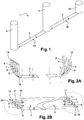
- a power supply unit 1 for recharging electric vehicles electric batteries comprises at least two power transmission modules 2a, 2b each having a horizontal bar 3 made of an electrical insulating material such as a resin, said bar 3 being elongated and traversed longitudinally by four electrical cables 5, 6, 7, 8.
- These four electrical cables are a neutral cable and three phase cables.
- the cables 5, 6, 7, 8 of one of the two modules 2b connect a pole 30 of the start and of the current supply of the electrical network, to a vertical column 9 serving as a power supply terminal to a vehicle battery.
- Each column 9 is preferably made of metal or solid plastic.
- each bar 3 is solid, flat and thin, and is made of an insulating material such as for example resin. More specifically, each bar 3 comprises a horizontal upper face 10 and a horizontal lower face 11, the width of said upper face 10 being smaller than the width of said lower face 11. Said two faces 10, 11 are superimposed while being centered. one on the other, so that the longitudinal axis of symmetry of the upper face 10 and the longitudinal axis of symmetry of the lower face 11 are in line with one another, and are part of the same vertical plane. The upper face 10 and the lower face 11 are connected to one another by means of two inclined lateral edges 12.
- Each bar 3 comprises a sheet 13 which extends over almost the entire length of said bar 3, that is to say over a length greater than 95% of the total length of said bar 3.
- the sheet 13 comprises a body main plane 14 and thin, delimited laterally by two folded longitudinal edges 15, at an angle between 70 ° and 90 ° with said body 14. Said two edges 15 have the same thickness as that of the main body 14. In other words, the sheet 13 has a U-shaped cross section.
- the body main 14 of the sheet 13 extends parallel to the upper face 10 and the lower face 11 of the bar 3 and is located closer to said upper face 10 than said lower face 11.
- the two side edges 15 of the sheet extend into the lower face 11 of the bar 3.
- said four cables 5, 6, 7, 8 are aligned in a plane which is parallel to the plane of the main body 14 of the plate 13, and which is parallel to the planes of the upper and lower faces 10, 11 of the bar 3
- Each bar 3 is supposed to rest on the ground.
- the sheet 13 makes it possible, on the one hand, to connect each column 9 or post 30 to a cable or earth rod located upstream of the system, and on the other hand, to protect said cables 5, 6, 7, 8 from any aggression outside, such as pickaxes. In this way, the plate 13 advantageously replaces a ground cable.
- the four cables 5, 6, 7, 8 emerge from the two ends 16, 17 of each bar 3, considered along its longitudinal axis.
- Each of said four cables 5, 6, 7, 8 has a double insulating outer sheath 18.
- the end zones of the four cables 5, 6, 7, 8 are folded upwards so as to make an angle of between 30 ° and 90 ° with the bar 3 in which they are implanted, said bar 3 being supposed to rest on the ground in a horizontal plane.
- the two modules 2a, 2b of a feed assembly 1 according to the invention are aligned and close to each other.
- the two bars 3 of the two modules 2a, 2b are perfectly aligned and in the extension of one another. They are only separated by a few centimeters.
- the emergent portions of the cables 5, 6, 7, 8 of the two ends of said bars 3 closest are electrically connected to each other at one of the two columns 9 serving as a power supply terminal. More specifically, the emerging portion of a cable at one end of a bar 3 is connected to the emerging portion of the cable from the end of the other bar 3 facing it. To do this, the two lugs 19 of two cables 5, 6, 7, 9 to be interconnected, are superimposed so as to match their openings 20. A fastening screw 21 is then introduced into the two superposed openings 20, and a nut 22 cooperates with said screw 21 to secure the two tabs 19 between them. Four connection bridges are thus made between the two bars 3.
- a power cable 45, 46, 47, 48 is electrically connected at each of said bridges to power a column 3 serving as a power supply terminal.
- Each of the two bars 3 has a nut 40, 41 to allow the attachment of a connection cable 42 between said two bars 3. More specifically, each nut 40, 41 is fixed to the plate 13 of each bar 3, and the connection cable 42 thus makes it possible to electrically connect the two bars 3 to each other.
- Each bar 3 has another nut 43 to allow the attachment of a power cable 44 of the column 9. More precisely this other nut 43 is fixed to the plate 13 of the bar 3 and the power cable 44 allows to electrically connect the column 9 to said sheet 13.
- Three columns 9 each serving as a power supply terminal for recharging the batteries of the vehicles, are located on the two aligned bars 3 of the two modules 2a, 2b. More specifically, two columns 9 are located at the two ends farthest from said bars 3, thus capping the four emergent parts of the cables 5, 6, 7, 8. A third column 9 is located at the two ends closest to said bars 3, thus capping the four connecting bridges between said bars 3.
Landscapes
- Engineering & Computer Science (AREA)
- Power Engineering (AREA)
- Transportation (AREA)
- Mechanical Engineering (AREA)
- Battery Mounting, Suspending (AREA)
- Electric Propulsion And Braking For Vehicles (AREA)
Applications Claiming Priority (1)
| Application Number | Priority Date | Filing Date | Title |
|---|---|---|---|
| FR1653634A FR3050406B1 (fr) | 2016-04-25 | 2016-04-25 | Ensemble d’alimentation destine a la recharge de batteries electriques de vehicules electriques |
Publications (2)
| Publication Number | Publication Date |
|---|---|
| EP3238977A1 true EP3238977A1 (de) | 2017-11-01 |
| EP3238977B1 EP3238977B1 (de) | 2023-06-14 |
Family
ID=56101731
Family Applications (1)
| Application Number | Title | Priority Date | Filing Date |
|---|---|---|---|
| EP17165168.0A Active EP3238977B1 (de) | 2016-04-25 | 2017-04-06 | Stromversorgungseinheit zum wiederaufladen von elektrischen batterien von elektrofahrzeugen |
Country Status (2)
| Country | Link |
|---|---|
| EP (1) | EP3238977B1 (de) |
| FR (1) | FR3050406B1 (de) |
Cited By (2)
| Publication number | Priority date | Publication date | Assignee | Title |
|---|---|---|---|---|
| DE102016225134A1 (de) * | 2016-12-15 | 2018-06-21 | Audi Ag | Ladeanordnung zur Versorgung eines elektrischen Verbrauchers und System |
| CN112078408A (zh) * | 2020-09-24 | 2020-12-15 | 广州奕极机电科技有限公司 | 一种新能源电动汽车用可移动式电动汽车充电桩 |
Citations (7)
| Publication number | Priority date | Publication date | Assignee | Title |
|---|---|---|---|---|
| FR321764A (fr) * | 1902-06-06 | 1903-01-19 | Pradier Marcel | Gaines à caniveaux pour conducteurs électriques et tuyaux |
| US6081205A (en) * | 1992-05-19 | 2000-06-27 | Williams; Douglas J. | Electronic parking meter and electric automobile recharging station |
| WO2010114455A1 (en) * | 2009-04-02 | 2010-10-07 | Hm Power Ab | Power outlet |
| US20120229085A1 (en) * | 2011-03-07 | 2012-09-13 | Lau David M K | System for charging electric vehicle batteries from street lights and parking meters |
| EP2792536A1 (de) * | 2013-04-16 | 2014-10-22 | Bluecarsharing | Selbsttragende Struktur, die eine Halterung für eine Ladestation umfasst, und entsprechende Ladestation |
| WO2014191644A1 (fr) | 2013-05-31 | 2014-12-04 | Nexans | Ensemble d'alimentation destine a la recharge de batteries electriques de vehicules automobiles electriques |
| US20150111423A1 (en) * | 2013-10-21 | 2015-04-23 | A.C. Dandy Products Ltd. | Protective apparatus for outdoor electrical outlets |
Family Cites Families (2)
| Publication number | Priority date | Publication date | Assignee | Title |
|---|---|---|---|---|
| US4165592A (en) * | 1978-01-24 | 1979-08-28 | Blankenship Roy L | Cable directing apparatus |
| GB2483064A (en) * | 2010-08-24 | 2012-02-29 | J F Plastics Ltd | Cable conduit |
-
2016
- 2016-04-25 FR FR1653634A patent/FR3050406B1/fr active Active
-
2017
- 2017-04-06 EP EP17165168.0A patent/EP3238977B1/de active Active
Patent Citations (7)
| Publication number | Priority date | Publication date | Assignee | Title |
|---|---|---|---|---|
| FR321764A (fr) * | 1902-06-06 | 1903-01-19 | Pradier Marcel | Gaines à caniveaux pour conducteurs électriques et tuyaux |
| US6081205A (en) * | 1992-05-19 | 2000-06-27 | Williams; Douglas J. | Electronic parking meter and electric automobile recharging station |
| WO2010114455A1 (en) * | 2009-04-02 | 2010-10-07 | Hm Power Ab | Power outlet |
| US20120229085A1 (en) * | 2011-03-07 | 2012-09-13 | Lau David M K | System for charging electric vehicle batteries from street lights and parking meters |
| EP2792536A1 (de) * | 2013-04-16 | 2014-10-22 | Bluecarsharing | Selbsttragende Struktur, die eine Halterung für eine Ladestation umfasst, und entsprechende Ladestation |
| WO2014191644A1 (fr) | 2013-05-31 | 2014-12-04 | Nexans | Ensemble d'alimentation destine a la recharge de batteries electriques de vehicules automobiles electriques |
| US20150111423A1 (en) * | 2013-10-21 | 2015-04-23 | A.C. Dandy Products Ltd. | Protective apparatus for outdoor electrical outlets |
Cited By (3)
| Publication number | Priority date | Publication date | Assignee | Title |
|---|---|---|---|---|
| DE102016225134A1 (de) * | 2016-12-15 | 2018-06-21 | Audi Ag | Ladeanordnung zur Versorgung eines elektrischen Verbrauchers und System |
| CN112078408A (zh) * | 2020-09-24 | 2020-12-15 | 广州奕极机电科技有限公司 | 一种新能源电动汽车用可移动式电动汽车充电桩 |
| CN112078408B (zh) * | 2020-09-24 | 2021-12-10 | 深圳百客新能源有限公司 | 一种新能源电动汽车用可移动式电动汽车充电桩 |
Also Published As
| Publication number | Publication date |
|---|---|
| FR3050406A1 (fr) | 2017-10-27 |
| EP3238977B1 (de) | 2023-06-14 |
| FR3050406B1 (fr) | 2018-04-27 |
Similar Documents
| Publication | Publication Date | Title |
|---|---|---|
| EP0330525B1 (de) | Vorgefertigte elektrische Kanalisation, anwendbar auf mehrere Nennströme vom Typ bestehend aus einem flachen kannelierten Isolationsträger für Leiterschienen | |
| FR2749441A1 (fr) | Borne de contact electrique femelle a pression de contact controlee | |
| FR2941565A1 (fr) | Unite photovoltaique de recuperation d'energie et ensemble photovoltaique comprenant une telle unite. | |
| EP3238977B1 (de) | Stromversorgungseinheit zum wiederaufladen von elektrischen batterien von elektrofahrzeugen | |
| FR2749443A1 (fr) | Borne de contact electrique femelle a zone de transition renforcee | |
| EP2249442A1 (de) | Befestigungsprofil eines elektrischen Geräts und Anlage, die ein solches Befestigungsprofil umfasst | |
| CA2871141A1 (fr) | Harnais de liaison de retour de courant, ainsi que procede de montage sur un cadre de fuselage composite | |
| FR2504315A1 (fr) | Element de connexion et dispositif de connexion, comportant de tels elements | |
| EP3005507B1 (de) | Stromversorgungseinrichtung zum wiederaufladen elektrischer batterien für elektrische fahrzeuge | |
| FR3029361A1 (fr) | Dispositif de connexion electrique | |
| WO2013088052A1 (fr) | Systeme de liaison equipotentielle pour panneau | |
| EP2383849B1 (de) | Vertikale elektrisch leitenden Verbindungsvorrichtung | |
| LU83379A1 (fr) | Dispositif de connexion electrique notamment pour meubles de bureau | |
| EP2662931B1 (de) | Anschlussschuh für isoliertes elektrisches Netzkabel, und Herstellungsverfahren dieses Anschlussschuhs | |
| EP3089295A1 (de) | Elektrische verbindungsvorrichtung zur spannungsausgleichsverbindung von einem kabelrinnenabschnitt mit eines stromkabelabschnitts | |
| FR2626723A1 (fr) | Dispositif deformable pour relier des conduits de distribution d'energie electrique | |
| EP1422799A1 (de) | Energieverteileranordnung für elektrische Geräte | |
| EP3336967B1 (de) | Elektrisches anschlusselement | |
| EP3633794A1 (de) | Anschluss | |
| EP3633690A1 (de) | Mehradriges stromkabel | |
| EP0335756B1 (de) | Anschlussvorrichtung zum Verbinden von zwei Kabelkanalenden | |
| FR2953073A3 (fr) | Dispositif pour relier electriquement au moins deux equipements electriques installes l'un au-dessus de l'autre dans une armoire de distribution electrique | |
| EP1065749A1 (de) | Verbindungszusatzgerät für elektrische Apparate, ins besondere für modulare elektrische Apparate | |
| FR2963986A1 (fr) | Dispositif de couverture de toiture de type panneau photovoltaique. | |
| FR2786612A1 (fr) | Dispositif de raccordement electrique entre un systeme a barres et plusieurs cables conducteurs |
Legal Events
| Date | Code | Title | Description |
|---|---|---|---|
| PUAI | Public reference made under article 153(3) epc to a published international application that has entered the european phase |
Free format text: ORIGINAL CODE: 0009012 |
|
| STAA | Information on the status of an ep patent application or granted ep patent |
Free format text: STATUS: THE APPLICATION HAS BEEN PUBLISHED |
|
| AK | Designated contracting states |
Kind code of ref document: A1 Designated state(s): AL AT BE BG CH CY CZ DE DK EE ES FI FR GB GR HR HU IE IS IT LI LT LU LV MC MK MT NL NO PL PT RO RS SE SI SK SM TR |
|
| AX | Request for extension of the european patent |
Extension state: BA ME |
|
| STAA | Information on the status of an ep patent application or granted ep patent |
Free format text: STATUS: REQUEST FOR EXAMINATION WAS MADE |
|
| 17P | Request for examination filed |
Effective date: 20180411 |
|
| RBV | Designated contracting states (corrected) |
Designated state(s): AL AT BE BG CH CY CZ DE DK EE ES FI FR GB GR HR HU IE IS IT LI LT LU LV MC MK MT NL NO PL PT RO RS SE SI SK SM TR |
|
| STAA | Information on the status of an ep patent application or granted ep patent |
Free format text: STATUS: EXAMINATION IS IN PROGRESS |
|
| 17Q | First examination report despatched |
Effective date: 20200827 |
|
| STAA | Information on the status of an ep patent application or granted ep patent |
Free format text: STATUS: EXAMINATION IS IN PROGRESS |
|
| STAA | Information on the status of an ep patent application or granted ep patent |
Free format text: STATUS: EXAMINATION IS IN PROGRESS |
|
| REG | Reference to a national code |
Ref country code: DE Ref legal event code: R079 Ref document number: 602017070143 Country of ref document: DE Free format text: PREVIOUS MAIN CLASS: B60L0011180000 Ipc: B60L0053300000 |
|
| RIC1 | Information provided on ipc code assigned before grant |
Ipc: B60L 53/30 20190101AFI20220921BHEP |
|
| GRAP | Despatch of communication of intention to grant a patent |
Free format text: ORIGINAL CODE: EPIDOSNIGR1 |
|
| STAA | Information on the status of an ep patent application or granted ep patent |
Free format text: STATUS: GRANT OF PATENT IS INTENDED |
|
| INTG | Intention to grant announced |
Effective date: 20230105 |
|
| GRAS | Grant fee paid |
Free format text: ORIGINAL CODE: EPIDOSNIGR3 |
|
| GRAA | (expected) grant |
Free format text: ORIGINAL CODE: 0009210 |
|
| STAA | Information on the status of an ep patent application or granted ep patent |
Free format text: STATUS: THE PATENT HAS BEEN GRANTED |
|
| AK | Designated contracting states |
Kind code of ref document: B1 Designated state(s): AL AT BE BG CH CY CZ DE DK EE ES FI FR GB GR HR HU IE IS IT LI LT LU LV MC MK MT NL NO PL PT RO RS SE SI SK SM TR |
|
| REG | Reference to a national code |
Ref country code: CH Ref legal event code: EP |
|
| REG | Reference to a national code |
Ref country code: DE Ref legal event code: R096 Ref document number: 602017070143 Country of ref document: DE |
|
| REG | Reference to a national code |
Ref country code: AT Ref legal event code: REF Ref document number: 1579009 Country of ref document: AT Kind code of ref document: T Effective date: 20230715 |
|
| REG | Reference to a national code |
Ref country code: LT Ref legal event code: MG9D |
|
| REG | Reference to a national code |
Ref country code: NL Ref legal event code: MP Effective date: 20230614 |
|
| PG25 | Lapsed in a contracting state [announced via postgrant information from national office to epo] |
Ref country code: SE Free format text: LAPSE BECAUSE OF FAILURE TO SUBMIT A TRANSLATION OF THE DESCRIPTION OR TO PAY THE FEE WITHIN THE PRESCRIBED TIME-LIMIT Effective date: 20230614 Ref country code: NO Free format text: LAPSE BECAUSE OF FAILURE TO SUBMIT A TRANSLATION OF THE DESCRIPTION OR TO PAY THE FEE WITHIN THE PRESCRIBED TIME-LIMIT Effective date: 20230914 Ref country code: ES Free format text: LAPSE BECAUSE OF FAILURE TO SUBMIT A TRANSLATION OF THE DESCRIPTION OR TO PAY THE FEE WITHIN THE PRESCRIBED TIME-LIMIT Effective date: 20230614 |
|
| REG | Reference to a national code |
Ref country code: AT Ref legal event code: MK05 Ref document number: 1579009 Country of ref document: AT Kind code of ref document: T Effective date: 20230614 |
|
| PG25 | Lapsed in a contracting state [announced via postgrant information from national office to epo] |
Ref country code: RS Free format text: LAPSE BECAUSE OF FAILURE TO SUBMIT A TRANSLATION OF THE DESCRIPTION OR TO PAY THE FEE WITHIN THE PRESCRIBED TIME-LIMIT Effective date: 20230614 Ref country code: NL Free format text: LAPSE BECAUSE OF FAILURE TO SUBMIT A TRANSLATION OF THE DESCRIPTION OR TO PAY THE FEE WITHIN THE PRESCRIBED TIME-LIMIT Effective date: 20230614 Ref country code: LV Free format text: LAPSE BECAUSE OF FAILURE TO SUBMIT A TRANSLATION OF THE DESCRIPTION OR TO PAY THE FEE WITHIN THE PRESCRIBED TIME-LIMIT Effective date: 20230614 Ref country code: LT Free format text: LAPSE BECAUSE OF FAILURE TO SUBMIT A TRANSLATION OF THE DESCRIPTION OR TO PAY THE FEE WITHIN THE PRESCRIBED TIME-LIMIT Effective date: 20230614 Ref country code: HR Free format text: LAPSE BECAUSE OF FAILURE TO SUBMIT A TRANSLATION OF THE DESCRIPTION OR TO PAY THE FEE WITHIN THE PRESCRIBED TIME-LIMIT Effective date: 20230614 Ref country code: GR Free format text: LAPSE BECAUSE OF FAILURE TO SUBMIT A TRANSLATION OF THE DESCRIPTION OR TO PAY THE FEE WITHIN THE PRESCRIBED TIME-LIMIT Effective date: 20230915 |
|
| PG25 | Lapsed in a contracting state [announced via postgrant information from national office to epo] |
Ref country code: FI Free format text: LAPSE BECAUSE OF FAILURE TO SUBMIT A TRANSLATION OF THE DESCRIPTION OR TO PAY THE FEE WITHIN THE PRESCRIBED TIME-LIMIT Effective date: 20230614 |
|
| PG25 | Lapsed in a contracting state [announced via postgrant information from national office to epo] |
Ref country code: SK Free format text: LAPSE BECAUSE OF FAILURE TO SUBMIT A TRANSLATION OF THE DESCRIPTION OR TO PAY THE FEE WITHIN THE PRESCRIBED TIME-LIMIT Effective date: 20230614 |
|
| PG25 | Lapsed in a contracting state [announced via postgrant information from national office to epo] |
Ref country code: IS Free format text: LAPSE BECAUSE OF FAILURE TO SUBMIT A TRANSLATION OF THE DESCRIPTION OR TO PAY THE FEE WITHIN THE PRESCRIBED TIME-LIMIT Effective date: 20231014 |
|
| PG25 | Lapsed in a contracting state [announced via postgrant information from national office to epo] |
Ref country code: SM Free format text: LAPSE BECAUSE OF FAILURE TO SUBMIT A TRANSLATION OF THE DESCRIPTION OR TO PAY THE FEE WITHIN THE PRESCRIBED TIME-LIMIT Effective date: 20230614 Ref country code: SK Free format text: LAPSE BECAUSE OF FAILURE TO SUBMIT A TRANSLATION OF THE DESCRIPTION OR TO PAY THE FEE WITHIN THE PRESCRIBED TIME-LIMIT Effective date: 20230614 Ref country code: RO Free format text: LAPSE BECAUSE OF FAILURE TO SUBMIT A TRANSLATION OF THE DESCRIPTION OR TO PAY THE FEE WITHIN THE PRESCRIBED TIME-LIMIT Effective date: 20230614 Ref country code: PT Free format text: LAPSE BECAUSE OF FAILURE TO SUBMIT A TRANSLATION OF THE DESCRIPTION OR TO PAY THE FEE WITHIN THE PRESCRIBED TIME-LIMIT Effective date: 20231016 Ref country code: IS Free format text: LAPSE BECAUSE OF FAILURE TO SUBMIT A TRANSLATION OF THE DESCRIPTION OR TO PAY THE FEE WITHIN THE PRESCRIBED TIME-LIMIT Effective date: 20231014 Ref country code: EE Free format text: LAPSE BECAUSE OF FAILURE TO SUBMIT A TRANSLATION OF THE DESCRIPTION OR TO PAY THE FEE WITHIN THE PRESCRIBED TIME-LIMIT Effective date: 20230614 Ref country code: CZ Free format text: LAPSE BECAUSE OF FAILURE TO SUBMIT A TRANSLATION OF THE DESCRIPTION OR TO PAY THE FEE WITHIN THE PRESCRIBED TIME-LIMIT Effective date: 20230614 Ref country code: AT Free format text: LAPSE BECAUSE OF FAILURE TO SUBMIT A TRANSLATION OF THE DESCRIPTION OR TO PAY THE FEE WITHIN THE PRESCRIBED TIME-LIMIT Effective date: 20230614 |
|
| PG25 | Lapsed in a contracting state [announced via postgrant information from national office to epo] |
Ref country code: PL Free format text: LAPSE BECAUSE OF FAILURE TO SUBMIT A TRANSLATION OF THE DESCRIPTION OR TO PAY THE FEE WITHIN THE PRESCRIBED TIME-LIMIT Effective date: 20230614 |
|
| REG | Reference to a national code |
Ref country code: DE Ref legal event code: R097 Ref document number: 602017070143 Country of ref document: DE |
|
| PLBE | No opposition filed within time limit |
Free format text: ORIGINAL CODE: 0009261 |
|
| STAA | Information on the status of an ep patent application or granted ep patent |
Free format text: STATUS: NO OPPOSITION FILED WITHIN TIME LIMIT |
|
| PG25 | Lapsed in a contracting state [announced via postgrant information from national office to epo] |
Ref country code: DK Free format text: LAPSE BECAUSE OF FAILURE TO SUBMIT A TRANSLATION OF THE DESCRIPTION OR TO PAY THE FEE WITHIN THE PRESCRIBED TIME-LIMIT Effective date: 20230614 |
|
| PG25 | Lapsed in a contracting state [announced via postgrant information from national office to epo] |
Ref country code: SI Free format text: LAPSE BECAUSE OF FAILURE TO SUBMIT A TRANSLATION OF THE DESCRIPTION OR TO PAY THE FEE WITHIN THE PRESCRIBED TIME-LIMIT Effective date: 20230614 |
|
| 26N | No opposition filed |
Effective date: 20240315 |
|
| PG25 | Lapsed in a contracting state [announced via postgrant information from national office to epo] |
Ref country code: SI Free format text: LAPSE BECAUSE OF FAILURE TO SUBMIT A TRANSLATION OF THE DESCRIPTION OR TO PAY THE FEE WITHIN THE PRESCRIBED TIME-LIMIT Effective date: 20230614 |
|
| PGFP | Annual fee paid to national office [announced via postgrant information from national office to epo] |
Ref country code: DE Payment date: 20240418 Year of fee payment: 8 |
|
| PGFP | Annual fee paid to national office [announced via postgrant information from national office to epo] |
Ref country code: IT Payment date: 20240424 Year of fee payment: 8 |
|
| PGFP | Annual fee paid to national office [announced via postgrant information from national office to epo] |
Ref country code: BE Payment date: 20240418 Year of fee payment: 8 |