EP3238646A2 - Cathéter à ballonnet irrigué avec ensemble d'électrodes à circuit flexible - Google Patents
Cathéter à ballonnet irrigué avec ensemble d'électrodes à circuit flexible Download PDFInfo
- Publication number
- EP3238646A2 EP3238646A2 EP17168393.1A EP17168393A EP3238646A2 EP 3238646 A2 EP3238646 A2 EP 3238646A2 EP 17168393 A EP17168393 A EP 17168393A EP 3238646 A2 EP3238646 A2 EP 3238646A2
- Authority
- EP
- European Patent Office
- Prior art keywords
- electrode
- contact
- balloon
- electrophysiology catheter
- catheter
- Prior art date
- Legal status (The legal status is an assumption and is not a legal conclusion. Google has not performed a legal analysis and makes no representation as to the accuracy of the status listed.)
- Ceased
Links
- 239000000758 substrate Substances 0.000 claims abstract description 65
- 230000007717 exclusion Effects 0.000 claims abstract description 30
- 239000012528 membrane Substances 0.000 claims description 43
- 229910000679 solder Inorganic materials 0.000 claims description 40
- 230000002262 irrigation Effects 0.000 claims description 29
- 238000003973 irrigation Methods 0.000 claims description 29
- 230000007831 electrophysiology Effects 0.000 claims description 19
- 238000002001 electrophysiology Methods 0.000 claims description 19
- PCHJSUWPFVWCPO-UHFFFAOYSA-N gold Chemical compound [Au] PCHJSUWPFVWCPO-UHFFFAOYSA-N 0.000 claims description 17
- 229910052737 gold Inorganic materials 0.000 claims description 17
- 239000010931 gold Substances 0.000 claims description 17
- 238000000034 method Methods 0.000 abstract description 27
- 210000003492 pulmonary vein Anatomy 0.000 abstract description 16
- 230000001225 therapeutic effect Effects 0.000 abstract description 3
- 230000008878 coupling Effects 0.000 abstract description 2
- 238000010168 coupling process Methods 0.000 abstract description 2
- 238000005859 coupling reaction Methods 0.000 abstract description 2
- 238000002679 ablation Methods 0.000 description 40
- 210000001519 tissue Anatomy 0.000 description 18
- RYGMFSIKBFXOCR-UHFFFAOYSA-N Copper Chemical compound [Cu] RYGMFSIKBFXOCR-UHFFFAOYSA-N 0.000 description 13
- 230000006870 function Effects 0.000 description 11
- 229910052802 copper Inorganic materials 0.000 description 7
- 239000010949 copper Substances 0.000 description 7
- 229920002120 photoresistant polymer Polymers 0.000 description 7
- 239000000523 sample Substances 0.000 description 7
- 239000012530 fluid Substances 0.000 description 6
- 229910001006 Constantan Inorganic materials 0.000 description 5
- 230000003902 lesion Effects 0.000 description 5
- 229920000139 polyethylene terephthalate Polymers 0.000 description 5
- 239000005020 polyethylene terephthalate Substances 0.000 description 5
- 239000004642 Polyimide Substances 0.000 description 4
- 230000008901 benefit Effects 0.000 description 4
- 238000010276 construction Methods 0.000 description 4
- 229920001721 polyimide Polymers 0.000 description 4
- 239000000853 adhesive Substances 0.000 description 3
- 230000001070 adhesive effect Effects 0.000 description 3
- 206010003119 arrhythmia Diseases 0.000 description 3
- 230000000712 assembly Effects 0.000 description 3
- 238000000429 assembly Methods 0.000 description 3
- 230000015572 biosynthetic process Effects 0.000 description 3
- 238000009529 body temperature measurement Methods 0.000 description 3
- 239000004020 conductor Substances 0.000 description 3
- 238000005516 engineering process Methods 0.000 description 3
- 238000005755 formation reaction Methods 0.000 description 3
- 210000005003 heart tissue Anatomy 0.000 description 3
- WABPQHHGFIMREM-UHFFFAOYSA-N lead(0) Chemical compound [Pb] WABPQHHGFIMREM-UHFFFAOYSA-N 0.000 description 3
- 229910052751 metal Inorganic materials 0.000 description 3
- 239000002184 metal Substances 0.000 description 3
- 238000004544 sputter deposition Methods 0.000 description 3
- 206010003130 Arrhythmia supraventricular Diseases 0.000 description 2
- 229920000106 Liquid crystal polymer Polymers 0.000 description 2
- 239000004977 Liquid-crystal polymers (LCPs) Substances 0.000 description 2
- KDLHZDBZIXYQEI-UHFFFAOYSA-N Palladium Chemical compound [Pd] KDLHZDBZIXYQEI-UHFFFAOYSA-N 0.000 description 2
- BQCADISMDOOEFD-UHFFFAOYSA-N Silver Chemical compound [Ag] BQCADISMDOOEFD-UHFFFAOYSA-N 0.000 description 2
- 210000003484 anatomy Anatomy 0.000 description 2
- 230000006793 arrhythmia Effects 0.000 description 2
- 239000000560 biocompatible material Substances 0.000 description 2
- 230000000747 cardiac effect Effects 0.000 description 2
- 238000003486 chemical etching Methods 0.000 description 2
- 238000005553 drilling Methods 0.000 description 2
- 238000002594 fluoroscopy Methods 0.000 description 2
- 210000002837 heart atrium Anatomy 0.000 description 2
- 210000005246 left atrium Anatomy 0.000 description 2
- 239000003550 marker Substances 0.000 description 2
- 230000000873 masking effect Effects 0.000 description 2
- 239000000463 material Substances 0.000 description 2
- 238000005259 measurement Methods 0.000 description 2
- 238000002844 melting Methods 0.000 description 2
- 230000008018 melting Effects 0.000 description 2
- 210000004165 myocardium Anatomy 0.000 description 2
- 230000037361 pathway Effects 0.000 description 2
- 230000002093 peripheral effect Effects 0.000 description 2
- 238000007747 plating Methods 0.000 description 2
- -1 polyethylene terephthalate Polymers 0.000 description 2
- 239000011148 porous material Substances 0.000 description 2
- 230000008569 process Effects 0.000 description 2
- 229910052709 silver Inorganic materials 0.000 description 2
- 239000004332 silver Substances 0.000 description 2
- 229920001187 thermosetting polymer Polymers 0.000 description 2
- WFKWXMTUELFFGS-UHFFFAOYSA-N tungsten Chemical compound [W] WFKWXMTUELFFGS-UHFFFAOYSA-N 0.000 description 2
- 229910052721 tungsten Inorganic materials 0.000 description 2
- 239000010937 tungsten Substances 0.000 description 2
- 230000000007 visual effect Effects 0.000 description 2
- 206010003658 Atrial Fibrillation Diseases 0.000 description 1
- 239000004593 Epoxy Substances 0.000 description 1
- 239000004696 Poly ether ether ketone Substances 0.000 description 1
- 229920002614 Polyether block amide Polymers 0.000 description 1
- FAPWRFPIFSIZLT-UHFFFAOYSA-M Sodium chloride Chemical compound [Na+].[Cl-] FAPWRFPIFSIZLT-UHFFFAOYSA-M 0.000 description 1
- RTAQQCXQSZGOHL-UHFFFAOYSA-N Titanium Chemical compound [Ti] RTAQQCXQSZGOHL-UHFFFAOYSA-N 0.000 description 1
- 230000006978 adaptation Effects 0.000 description 1
- 230000003044 adaptive effect Effects 0.000 description 1
- 230000004075 alteration Effects 0.000 description 1
- 238000004873 anchoring Methods 0.000 description 1
- JUPQTSLXMOCDHR-UHFFFAOYSA-N benzene-1,4-diol;bis(4-fluorophenyl)methanone Chemical compound OC1=CC=C(O)C=C1.C1=CC(F)=CC=C1C(=O)C1=CC=C(F)C=C1 JUPQTSLXMOCDHR-UHFFFAOYSA-N 0.000 description 1
- 239000012620 biological material Substances 0.000 description 1
- 210000002318 cardia Anatomy 0.000 description 1
- 238000013153 catheter ablation Methods 0.000 description 1
- 239000012141 concentrate Substances 0.000 description 1
- 238000001816 cooling Methods 0.000 description 1
- 238000012937 correction Methods 0.000 description 1
- 238000000354 decomposition reaction Methods 0.000 description 1
- 238000001514 detection method Methods 0.000 description 1
- 229910003460 diamond Inorganic materials 0.000 description 1
- 239000010432 diamond Substances 0.000 description 1
- 238000007599 discharging Methods 0.000 description 1
- 229920002457 flexible plastic Polymers 0.000 description 1
- 239000011888 foil Substances 0.000 description 1
- 230000017525 heat dissipation Effects 0.000 description 1
- 238000002347 injection Methods 0.000 description 1
- 239000007924 injection Substances 0.000 description 1
- 238000002955 isolation Methods 0.000 description 1
- 238000010030 laminating Methods 0.000 description 1
- 238000003475 lamination Methods 0.000 description 1
- 238000004519 manufacturing process Methods 0.000 description 1
- 238000013507 mapping Methods 0.000 description 1
- 239000000203 mixture Substances 0.000 description 1
- 230000002107 myocardial effect Effects 0.000 description 1
- 229910001000 nickel titanium Inorganic materials 0.000 description 1
- HLXZNVUGXRDIFK-UHFFFAOYSA-N nickel titanium Chemical compound [Ti].[Ti].[Ti].[Ti].[Ti].[Ti].[Ti].[Ti].[Ti].[Ti].[Ti].[Ni].[Ni].[Ni].[Ni].[Ni].[Ni].[Ni].[Ni].[Ni].[Ni].[Ni].[Ni].[Ni].[Ni] HLXZNVUGXRDIFK-UHFFFAOYSA-N 0.000 description 1
- 230000003287 optical effect Effects 0.000 description 1
- 229910052763 palladium Inorganic materials 0.000 description 1
- 230000000149 penetrating effect Effects 0.000 description 1
- 239000004033 plastic Substances 0.000 description 1
- 229920003023 plastic Polymers 0.000 description 1
- 229920000728 polyester Polymers 0.000 description 1
- 229920006267 polyester film Polymers 0.000 description 1
- 229920002530 polyetherether ketone Polymers 0.000 description 1
- 229920000642 polymer Polymers 0.000 description 1
- 229920002635 polyurethane Polymers 0.000 description 1
- 239000004814 polyurethane Substances 0.000 description 1
- 238000007674 radiofrequency ablation Methods 0.000 description 1
- 230000033764 rhythmic process Effects 0.000 description 1
- 238000005476 soldering Methods 0.000 description 1
- 238000003860 storage Methods 0.000 description 1
- 229910052719 titanium Inorganic materials 0.000 description 1
- 239000010936 titanium Substances 0.000 description 1
- 238000012546 transfer Methods 0.000 description 1
- 239000011800 void material Substances 0.000 description 1
Images


Classifications
-
- A—HUMAN NECESSITIES
- A61—MEDICAL OR VETERINARY SCIENCE; HYGIENE
- A61B—DIAGNOSIS; SURGERY; IDENTIFICATION
- A61B18/00—Surgical instruments, devices or methods for transferring non-mechanical forms of energy to or from the body
- A61B18/04—Surgical instruments, devices or methods for transferring non-mechanical forms of energy to or from the body by heating
- A61B18/12—Surgical instruments, devices or methods for transferring non-mechanical forms of energy to or from the body by heating by passing a current through the tissue to be heated, e.g. high-frequency current
- A61B18/14—Probes or electrodes therefor
- A61B18/1492—Probes or electrodes therefor having a flexible, catheter-like structure, e.g. for heart ablation
-
- A—HUMAN NECESSITIES
- A61—MEDICAL OR VETERINARY SCIENCE; HYGIENE
- A61B—DIAGNOSIS; SURGERY; IDENTIFICATION
- A61B5/00—Measuring for diagnostic purposes; Identification of persons
- A61B5/24—Detecting, measuring or recording bioelectric or biomagnetic signals of the body or parts thereof
- A61B5/25—Bioelectric electrodes therefor
- A61B5/279—Bioelectric electrodes therefor specially adapted for particular uses
- A61B5/28—Bioelectric electrodes therefor specially adapted for particular uses for electrocardiography [ECG]
- A61B5/283—Invasive
- A61B5/287—Holders for multiple electrodes, e.g. electrode catheters for electrophysiological study [EPS]
-
- A—HUMAN NECESSITIES
- A61—MEDICAL OR VETERINARY SCIENCE; HYGIENE
- A61B—DIAGNOSIS; SURGERY; IDENTIFICATION
- A61B5/00—Measuring for diagnostic purposes; Identification of persons
- A61B5/68—Arrangements of detecting, measuring or recording means, e.g. sensors, in relation to patient
- A61B5/6846—Arrangements of detecting, measuring or recording means, e.g. sensors, in relation to patient specially adapted to be brought in contact with an internal body part, i.e. invasive
- A61B5/6847—Arrangements of detecting, measuring or recording means, e.g. sensors, in relation to patient specially adapted to be brought in contact with an internal body part, i.e. invasive mounted on an invasive device
- A61B5/6852—Catheters
- A61B5/6853—Catheters with a balloon
-
- A—HUMAN NECESSITIES
- A61—MEDICAL OR VETERINARY SCIENCE; HYGIENE
- A61B—DIAGNOSIS; SURGERY; IDENTIFICATION
- A61B5/00—Measuring for diagnostic purposes; Identification of persons
- A61B5/68—Arrangements of detecting, measuring or recording means, e.g. sensors, in relation to patient
- A61B5/6846—Arrangements of detecting, measuring or recording means, e.g. sensors, in relation to patient specially adapted to be brought in contact with an internal body part, i.e. invasive
- A61B5/6847—Arrangements of detecting, measuring or recording means, e.g. sensors, in relation to patient specially adapted to be brought in contact with an internal body part, i.e. invasive mounted on an invasive device
- A61B5/6852—Catheters
- A61B5/6857—Catheters with a distal pigtail shape
-
- A—HUMAN NECESSITIES
- A61—MEDICAL OR VETERINARY SCIENCE; HYGIENE
- A61M—DEVICES FOR INTRODUCING MEDIA INTO, OR ONTO, THE BODY; DEVICES FOR TRANSDUCING BODY MEDIA OR FOR TAKING MEDIA FROM THE BODY; DEVICES FOR PRODUCING OR ENDING SLEEP OR STUPOR
- A61M25/00—Catheters; Hollow probes
- A61M25/10—Balloon catheters
-
- B—PERFORMING OPERATIONS; TRANSPORTING
- B29—WORKING OF PLASTICS; WORKING OF SUBSTANCES IN A PLASTIC STATE IN GENERAL
- B29C—SHAPING OR JOINING OF PLASTICS; SHAPING OF MATERIAL IN A PLASTIC STATE, NOT OTHERWISE PROVIDED FOR; AFTER-TREATMENT OF THE SHAPED PRODUCTS, e.g. REPAIRING
- B29C65/00—Joining or sealing of preformed parts, e.g. welding of plastics materials; Apparatus therefor
- B29C65/02—Joining or sealing of preformed parts, e.g. welding of plastics materials; Apparatus therefor by heating, with or without pressure
- B29C65/14—Joining or sealing of preformed parts, e.g. welding of plastics materials; Apparatus therefor by heating, with or without pressure using wave energy, i.e. electromagnetic radiation, or particle radiation
- B29C65/16—Laser beams
-
- B—PERFORMING OPERATIONS; TRANSPORTING
- B29—WORKING OF PLASTICS; WORKING OF SUBSTANCES IN A PLASTIC STATE IN GENERAL
- B29C—SHAPING OR JOINING OF PLASTICS; SHAPING OF MATERIAL IN A PLASTIC STATE, NOT OTHERWISE PROVIDED FOR; AFTER-TREATMENT OF THE SHAPED PRODUCTS, e.g. REPAIRING
- B29C65/00—Joining or sealing of preformed parts, e.g. welding of plastics materials; Apparatus therefor
- B29C65/48—Joining or sealing of preformed parts, e.g. welding of plastics materials; Apparatus therefor using adhesives, i.e. using supplementary joining material; solvent bonding
-
- G—PHYSICS
- G03—PHOTOGRAPHY; CINEMATOGRAPHY; ANALOGOUS TECHNIQUES USING WAVES OTHER THAN OPTICAL WAVES; ELECTROGRAPHY; HOLOGRAPHY
- G03F—PHOTOMECHANICAL PRODUCTION OF TEXTURED OR PATTERNED SURFACES, e.g. FOR PRINTING, FOR PROCESSING OF SEMICONDUCTOR DEVICES; MATERIALS THEREFOR; ORIGINALS THEREFOR; APPARATUS SPECIALLY ADAPTED THEREFOR
- G03F7/00—Photomechanical, e.g. photolithographic, production of textured or patterned surfaces, e.g. printing surfaces; Materials therefor, e.g. comprising photoresists; Apparatus specially adapted therefor
- G03F7/16—Coating processes; Apparatus therefor
-
- H—ELECTRICITY
- H05—ELECTRIC TECHNIQUES NOT OTHERWISE PROVIDED FOR
- H05K—PRINTED CIRCUITS; CASINGS OR CONSTRUCTIONAL DETAILS OF ELECTRIC APPARATUS; MANUFACTURE OF ASSEMBLAGES OF ELECTRICAL COMPONENTS
- H05K3/00—Apparatus or processes for manufacturing printed circuits
- H05K3/40—Forming printed elements for providing electric connections to or between printed circuits
- H05K3/4038—Through-connections; Vertical interconnect access [VIA] connections
-
- H—ELECTRICITY
- H05—ELECTRIC TECHNIQUES NOT OTHERWISE PROVIDED FOR
- H05K—PRINTED CIRCUITS; CASINGS OR CONSTRUCTIONAL DETAILS OF ELECTRIC APPARATUS; MANUFACTURE OF ASSEMBLAGES OF ELECTRICAL COMPONENTS
- H05K3/00—Apparatus or processes for manufacturing printed circuits
- H05K3/46—Manufacturing multilayer circuits
- H05K3/4644—Manufacturing multilayer circuits by building the multilayer layer by layer, i.e. build-up multilayer circuits
-
- A—HUMAN NECESSITIES
- A61—MEDICAL OR VETERINARY SCIENCE; HYGIENE
- A61B—DIAGNOSIS; SURGERY; IDENTIFICATION
- A61B17/00—Surgical instruments, devices or methods, e.g. tourniquets
- A61B2017/00526—Methods of manufacturing
-
- A—HUMAN NECESSITIES
- A61—MEDICAL OR VETERINARY SCIENCE; HYGIENE
- A61B—DIAGNOSIS; SURGERY; IDENTIFICATION
- A61B18/00—Surgical instruments, devices or methods for transferring non-mechanical forms of energy to or from the body
- A61B2018/00005—Cooling or heating of the probe or tissue immediately surrounding the probe
- A61B2018/00011—Cooling or heating of the probe or tissue immediately surrounding the probe with fluids
- A61B2018/00029—Cooling or heating of the probe or tissue immediately surrounding the probe with fluids open
-
- A—HUMAN NECESSITIES
- A61—MEDICAL OR VETERINARY SCIENCE; HYGIENE
- A61B—DIAGNOSIS; SURGERY; IDENTIFICATION
- A61B18/00—Surgical instruments, devices or methods for transferring non-mechanical forms of energy to or from the body
- A61B2018/00053—Mechanical features of the instrument of device
- A61B2018/00059—Material properties
- A61B2018/00071—Electrical conductivity
- A61B2018/00083—Electrical conductivity low, i.e. electrically insulating
-
- A—HUMAN NECESSITIES
- A61—MEDICAL OR VETERINARY SCIENCE; HYGIENE
- A61B—DIAGNOSIS; SURGERY; IDENTIFICATION
- A61B18/00—Surgical instruments, devices or methods for transferring non-mechanical forms of energy to or from the body
- A61B2018/00053—Mechanical features of the instrument of device
- A61B2018/0016—Energy applicators arranged in a two- or three dimensional array
-
- A—HUMAN NECESSITIES
- A61—MEDICAL OR VETERINARY SCIENCE; HYGIENE
- A61B—DIAGNOSIS; SURGERY; IDENTIFICATION
- A61B18/00—Surgical instruments, devices or methods for transferring non-mechanical forms of energy to or from the body
- A61B2018/00053—Mechanical features of the instrument of device
- A61B2018/00214—Expandable means emitting energy, e.g. by elements carried thereon
- A61B2018/0022—Balloons
- A61B2018/0025—Multiple balloons
- A61B2018/00261—Multiple balloons arranged in a line
-
- A—HUMAN NECESSITIES
- A61—MEDICAL OR VETERINARY SCIENCE; HYGIENE
- A61B—DIAGNOSIS; SURGERY; IDENTIFICATION
- A61B18/00—Surgical instruments, devices or methods for transferring non-mechanical forms of energy to or from the body
- A61B2018/00315—Surgical instruments, devices or methods for transferring non-mechanical forms of energy to or from the body for treatment of particular body parts
- A61B2018/00345—Vascular system
- A61B2018/00351—Heart
- A61B2018/00357—Endocardium
-
- A—HUMAN NECESSITIES
- A61—MEDICAL OR VETERINARY SCIENCE; HYGIENE
- A61B—DIAGNOSIS; SURGERY; IDENTIFICATION
- A61B18/00—Surgical instruments, devices or methods for transferring non-mechanical forms of energy to or from the body
- A61B2018/00315—Surgical instruments, devices or methods for transferring non-mechanical forms of energy to or from the body for treatment of particular body parts
- A61B2018/00345—Vascular system
- A61B2018/00351—Heart
- A61B2018/00375—Ostium, e.g. ostium of pulmonary vein or artery
-
- A—HUMAN NECESSITIES
- A61—MEDICAL OR VETERINARY SCIENCE; HYGIENE
- A61B—DIAGNOSIS; SURGERY; IDENTIFICATION
- A61B18/00—Surgical instruments, devices or methods for transferring non-mechanical forms of energy to or from the body
- A61B2018/00571—Surgical instruments, devices or methods for transferring non-mechanical forms of energy to or from the body for achieving a particular surgical effect
- A61B2018/00577—Ablation
-
- A—HUMAN NECESSITIES
- A61—MEDICAL OR VETERINARY SCIENCE; HYGIENE
- A61B—DIAGNOSIS; SURGERY; IDENTIFICATION
- A61B18/00—Surgical instruments, devices or methods for transferring non-mechanical forms of energy to or from the body
- A61B2018/00636—Sensing and controlling the application of energy
- A61B2018/00642—Sensing and controlling the application of energy with feedback, i.e. closed loop control
-
- A—HUMAN NECESSITIES
- A61—MEDICAL OR VETERINARY SCIENCE; HYGIENE
- A61B—DIAGNOSIS; SURGERY; IDENTIFICATION
- A61B18/00—Surgical instruments, devices or methods for transferring non-mechanical forms of energy to or from the body
- A61B2018/00636—Sensing and controlling the application of energy
- A61B2018/00696—Controlled or regulated parameters
- A61B2018/00702—Power or energy
-
- A—HUMAN NECESSITIES
- A61—MEDICAL OR VETERINARY SCIENCE; HYGIENE
- A61B—DIAGNOSIS; SURGERY; IDENTIFICATION
- A61B18/00—Surgical instruments, devices or methods for transferring non-mechanical forms of energy to or from the body
- A61B2018/00636—Sensing and controlling the application of energy
- A61B2018/00773—Sensed parameters
- A61B2018/00791—Temperature
- A61B2018/00821—Temperature measured by a thermocouple
-
- A—HUMAN NECESSITIES
- A61—MEDICAL OR VETERINARY SCIENCE; HYGIENE
- A61B—DIAGNOSIS; SURGERY; IDENTIFICATION
- A61B18/00—Surgical instruments, devices or methods for transferring non-mechanical forms of energy to or from the body
- A61B2018/00636—Sensing and controlling the application of energy
- A61B2018/00773—Sensed parameters
- A61B2018/00839—Bioelectrical parameters, e.g. ECG, EEG
-
- A—HUMAN NECESSITIES
- A61—MEDICAL OR VETERINARY SCIENCE; HYGIENE
- A61B—DIAGNOSIS; SURGERY; IDENTIFICATION
- A61B18/00—Surgical instruments, devices or methods for transferring non-mechanical forms of energy to or from the body
- A61B2018/00636—Sensing and controlling the application of energy
- A61B2018/00773—Sensed parameters
- A61B2018/00892—Voltage
-
- A—HUMAN NECESSITIES
- A61—MEDICAL OR VETERINARY SCIENCE; HYGIENE
- A61B—DIAGNOSIS; SURGERY; IDENTIFICATION
- A61B18/00—Surgical instruments, devices or methods for transferring non-mechanical forms of energy to or from the body
- A61B18/04—Surgical instruments, devices or methods for transferring non-mechanical forms of energy to or from the body by heating
- A61B18/12—Surgical instruments, devices or methods for transferring non-mechanical forms of energy to or from the body by heating by passing a current through the tissue to be heated, e.g. high-frequency current
- A61B18/14—Probes or electrodes therefor
- A61B2018/1405—Electrodes having a specific shape
- A61B2018/1407—Loop
-
- A—HUMAN NECESSITIES
- A61—MEDICAL OR VETERINARY SCIENCE; HYGIENE
- A61B—DIAGNOSIS; SURGERY; IDENTIFICATION
- A61B18/00—Surgical instruments, devices or methods for transferring non-mechanical forms of energy to or from the body
- A61B18/04—Surgical instruments, devices or methods for transferring non-mechanical forms of energy to or from the body by heating
- A61B18/12—Surgical instruments, devices or methods for transferring non-mechanical forms of energy to or from the body by heating by passing a current through the tissue to be heated, e.g. high-frequency current
- A61B18/14—Probes or electrodes therefor
- A61B2018/1405—Electrodes having a specific shape
- A61B2018/1417—Ball
-
- A—HUMAN NECESSITIES
- A61—MEDICAL OR VETERINARY SCIENCE; HYGIENE
- A61B—DIAGNOSIS; SURGERY; IDENTIFICATION
- A61B18/00—Surgical instruments, devices or methods for transferring non-mechanical forms of energy to or from the body
- A61B18/04—Surgical instruments, devices or methods for transferring non-mechanical forms of energy to or from the body by heating
- A61B18/12—Surgical instruments, devices or methods for transferring non-mechanical forms of energy to or from the body by heating by passing a current through the tissue to be heated, e.g. high-frequency current
- A61B18/14—Probes or electrodes therefor
- A61B2018/1465—Deformable electrodes
-
- A—HUMAN NECESSITIES
- A61—MEDICAL OR VETERINARY SCIENCE; HYGIENE
- A61B—DIAGNOSIS; SURGERY; IDENTIFICATION
- A61B18/00—Surgical instruments, devices or methods for transferring non-mechanical forms of energy to or from the body
- A61B18/04—Surgical instruments, devices or methods for transferring non-mechanical forms of energy to or from the body by heating
- A61B18/12—Surgical instruments, devices or methods for transferring non-mechanical forms of energy to or from the body by heating by passing a current through the tissue to be heated, e.g. high-frequency current
- A61B18/14—Probes or electrodes therefor
- A61B2018/1497—Electrodes covering only part of the probe circumference
-
- A—HUMAN NECESSITIES
- A61—MEDICAL OR VETERINARY SCIENCE; HYGIENE
- A61B—DIAGNOSIS; SURGERY; IDENTIFICATION
- A61B2218/00—Details of surgical instruments, devices or methods for transferring non-mechanical forms of energy to or from the body
- A61B2218/001—Details of surgical instruments, devices or methods for transferring non-mechanical forms of energy to or from the body having means for irrigation and/or aspiration of substances to and/or from the surgical site
- A61B2218/002—Irrigation
-
- A—HUMAN NECESSITIES
- A61—MEDICAL OR VETERINARY SCIENCE; HYGIENE
- A61B—DIAGNOSIS; SURGERY; IDENTIFICATION
- A61B2562/00—Details of sensors; Constructional details of sensor housings or probes; Accessories for sensors
- A61B2562/12—Manufacturing methods specially adapted for producing sensors for in-vivo measurements
- A61B2562/125—Manufacturing methods specially adapted for producing sensors for in-vivo measurements characterised by the manufacture of electrodes
-
- A—HUMAN NECESSITIES
- A61—MEDICAL OR VETERINARY SCIENCE; HYGIENE
- A61B—DIAGNOSIS; SURGERY; IDENTIFICATION
- A61B2562/00—Details of sensors; Constructional details of sensor housings or probes; Accessories for sensors
- A61B2562/16—Details of sensor housings or probes; Details of structural supports for sensors
- A61B2562/164—Details of sensor housings or probes; Details of structural supports for sensors the sensor is mounted in or on a conformable substrate or carrier
-
- A—HUMAN NECESSITIES
- A61—MEDICAL OR VETERINARY SCIENCE; HYGIENE
- A61M—DEVICES FOR INTRODUCING MEDIA INTO, OR ONTO, THE BODY; DEVICES FOR TRANSDUCING BODY MEDIA OR FOR TAKING MEDIA FROM THE BODY; DEVICES FOR PRODUCING OR ENDING SLEEP OR STUPOR
- A61M25/00—Catheters; Hollow probes
- A61M25/10—Balloon catheters
- A61M2025/1043—Balloon catheters with special features or adapted for special applications
- A61M2025/1086—Balloon catheters with special features or adapted for special applications having a special balloon surface topography, e.g. pores, protuberances, spikes or grooves
-
- B—PERFORMING OPERATIONS; TRANSPORTING
- B29—WORKING OF PLASTICS; WORKING OF SUBSTANCES IN A PLASTIC STATE IN GENERAL
- B29L—INDEXING SCHEME ASSOCIATED WITH SUBCLASS B29C, RELATING TO PARTICULAR ARTICLES
- B29L2031/00—Other particular articles
- B29L2031/753—Medical equipment; Accessories therefor
- B29L2031/7542—Catheters
Definitions
- This invention relates to medical devices. More particularly, this invention relates to improvements in cardiac catheterization, including electrophysiologic (EP) catheters, in particular, EP catheters for mapping and/or ablating ostia and tubular regions in the heart.
- EP electrophysiologic
- Cardiac arrhythmias such as atrial fibrillation, occur when regions of cardiac tissue abnormally conduct electric signals to adjacent tissue, thereby disrupting the normal cardiac cycle and causing asynchronous rhythm.
- Procedures for treating arrhythmia include surgically disrupting the origin of the signals causing the arrhythmia, as well as disrupting the conducting pathway for such signals.
- By selectively ablating cardiac tissue by application of energy via a catheter it is sometimes possible to cease or modify the propagation of unwanted electrical signals from one portion of the heart to another.
- the ablation process destroys the unwanted electrical pathways by formation of non-conducting lesions.
- Circumferential lesions at or near the ostia of the pulmonary veins have been created to treat atrial arrhythmias.
- U.S. Pat. Nos. 6,012,457 and 6,024,740 both to Lesh, disclose a radially expandable ablation device, which includes a radiofrequency electrode. Using this device, it is proposed to deliver radiofrequency energy to the pulmonary veins in order to establish a circumferential conduction block, thereby electrically isolating the pulmonary veins from the left atrium.
- U.S. Pat. No. 6,814,733 to Schwartz et al. which is commonly assigned herewith and herein incorporated by reference, describes a catheter introduction apparatus having a radially expandable helical coil as a radiofrequency emitter.
- the emitter is introduced percutaneously, and transseptally advanced to the ostium of a pulmonary vein.
- the emitter is radially expanded, which can be accomplished by inflating an anchoring balloon about which the emitter is wrapped, in order to cause the emitter to make circumferential contact with the inner wall of the pulmonary vein.
- the coil is energized by a radiofrequency generator, and a circumferential ablation lesion is produced in the myocardial sleeve of the pulmonary vein, which effectively blocks electrical propagation between the pulmonary vein and the left atrium.
- U.S. Pat. No. 7,340,307 to Maguire, et al. proposes a tissue ablation system and method that treats atrial arrhythmia by ablating a circumferential region of tissue at a location where a pulmonary vein extends from an atrium.
- the system includes a circumferential ablation member with an ablation element and includes a delivery assembly for delivering the ablation member to the location.
- the circumferential ablation member is generally adjustable between different configurations to allow both the delivery through a delivery sheath into the atrium and the ablative coupling between the ablation element and the circumferential region of tissue.
- inflatable catheter electrode assemblies have been constructed with flex circuits to provide the outer surface of the inflatable electrode assemblies with a multitude of very small electrodes.
- catheter balloon structures are described in U.S. Publication No. 2016/0175041 , titled Balloon for Ablation Around Pulmonary Vein, the entire content of which is incorporated herein by reference.
- Flex circuits or flexible electronics involve a technology for assembling electronic circuits by mounting electronic devices on flexible plastic substrates, such as polyimide, Liquid Crystal Polymer (LCP), PEEK or transparent conductive polyester film (PET). Additionally, flex circuits can be screen printed silver circuits on polyester. Flexible printed circuits (FPC) are made with a photolithographic technology. An alternative way of making flexible foil circuits or flexible flat cables (FFCs) is laminating very thin (0.07 mm) copper strips in between two layers of PET. These PET layers, typically 0.05 mm thick, are coated with an adhesive which is thermosetting, and will be activated during the lamination process.
- LCP Liquid Crystal Polymer
- PEEK transparent conductive polyester film
- FPC Flexible printed circuits
- FPC Flexible printed circuits
- An alternative way of making flexible foil circuits or flexible flat cables (FFCs) is laminating very thin (0.07 mm) copper strips in between two layers of PET. These PET layers, typically 0.05 mm thick, are coated with an adhesive which
- Single-sided flexible circuits have a single conductor layer made of either a metal or conductive (metal filled) polymer on a flexible dielectric film. Component termination features are accessible only from one side. Holes may be formed in the base film to allow component leads to pass through for interconnection, normally by soldering.
- ostia and tubular regions in the heart come in all sizes.
- conventional balloon or inflatable catheters may not have necessary flexibility to accommodate different shapes and sizes while having sufficient structural support for effective circumferential contact with tissue.
- ablation electrodes that provide greater surface contact may lack sufficient flexibility.
- delicate wires such as those of electrode lead wires and/or thermocouple wires and their solder joints need support and protection from breakage and damage during both assembly and use in the patient's body.
- the balloon configuration is radially symmetrical and multiple electrode elements surround the balloon configuration, determining the orientation of the balloon electrode assembly under fluoroscopy has also posed challenges.
- a balloon or a catheter having an inflatable member with contact electrodes that can contact more tissue area while remaining sufficiently flexible to accommodate different anatomy and the tighter space constraints of an ostium and a pulmonary vein.
- a balloon catheter to carry an electrode assembly with adaptations for the ostium and pulmonary vein that can be manufactured from a generic flexible circuit.
- a balloon catheter capable of multiple functions including diagnostic and therapeutic functions, such as ablation, pacing, navigation, temperature sensing, electropotential sensing and impedance sensing, and be adaptive for use with other catheters, including a lasso catheter or a focal catheter.
- the present invention is directed to a catheter having an irrigated inflatable balloon adapted for use in an ostium of a pulmonary vein.
- the balloon includes a flexible circuit electrode assembly adapted for circumferential contact with the ostium when the balloon is inflated.
- the balloon catheter is well suited for both diagnostic and therapeutic applications and procedures and may be used with a lasso catheter or focal catheter.
- an electrophysiology catheter adapted for use in an ostium, includes a balloon having an membrane, the balloon having a distal end and a proximal end defining a longitudinal axis; and a contact electrode supported on the membrane, the contact electrode configured for contact with the ostium, the contact electrode having a "fishbone" configuration with a longitudinally elongated portion and a plurality of transversal fingers.
- the transversal fingers have different lengths and the contact electrode has longer fingers and shorter fingers, the longer fingers being situated near an equatorial region of the balloon.
- the plurality of fingers may include a distal finger, a proximal finger and fingers in between, wherein each of the fingers in between has a shorter adjacent finger.
- a width of the elongated portion may be greater than a width of each finger.
- the plurality of fingers may be generally evenly spaced along the elongated portion.
- the plurality of fingers may have a generally uniform width.
- the contact electrode comprises gold.
- the contact electrode may include a seed layer below the gold.
- a balloon may have a plurality of contact electrodes generally evenly radially distributed on its membrane.
- an electrophysiology catheter includes a balloon with a membrane, and a flex circuit electrode assembly on the membrane.
- the flex circuit has a substrate having a first surface and a second surface, a contact electrode on the first surface, a wiring electrode on the second surface, and a conductive via extending through the substrate and adapted to conductively connect the contact electrode and the wiring electrode.
- the substrate includes a first irrigation aperture
- the membrane includes a second irrigation aperture aligned with the first irrigation aperture.
- the contact electrode may include an exclusion zone surrounding the first irrigation aperture
- the wiring electrode may include an exclusion zone surrounding the first irrigation aperture.
- the wiring electrode may have an elongated body longitudinally aligned with the elongated portion.
- the wiring electrode may include a solder pad, wherein the flex circuit electrode assembly includes a wire pair conductively connected to the solder pad.
- the flex circuit electrode includes a "fishbone" contact microelectrode, a "spine” wiring microelectrode, and a conductive via configured to conductively couple the contact microelectrode and the wiring electrode.
- the microelectrodes are strategically positioned relative to the electrodes to be close and proximate thereto but yet be physically and electrically isolated therefrom.
- the flex circuit electrode includes at least one exclusion zone configured to physically and electrically isolate the microelectrodes from the contact electrode and the wiring electrode.
- a microelectrode may be configured as an "island" surrounded circumferentially in its entirety by a contact electrode or a wiring electrode and physically and electrically isolated therefrom by an exclusion zone.
- the flex circuit electrode includes a proximal tail.
- Conductive wires configured for conductive connection to the contact electrode and/or the wiring electrode may extend between the proximal tail and the balloon membrane toward a shaft of the balloon catheter.
- the conductive wires may extend through a through-hole formed in the balloon membrane to enter an interior of the balloon.
- the contact electrode and the wiring electrode may be split into a plurality of portions, with a respective contact electrode portion and a respective wiring electrode portion being conductively coupled by a conductive via. Conductive wires are provided for each conductively connected pair of contact electrode portion and wiring electrode portion. Each split electrode portion may surround a respective microelectrode physically and electrically isolated by an exclusion zone.
- conductive wires configured for conductive connection to the electrodes and the microelectrodes may be included in a ribbon cable.
- the ribbon cable may pass into an interior of the balloon through a through-hole formed in the balloon membrane.
- the ribbon cable may extend between a tail of the flex circuit electrode assembly and the balloon membrane toward proximal end of the balloon before entering a shaft proximal of the balloon.
- the flex circuit electrode assembly includes a thermocouple for use with a contact microelectrode, where the thermocouple has a wire pair which are embedded in the flex circuit substrate and connected to each other by a conducting via conductively coupled to the contact electrode.
- the thermocouple is configured to measure temperature of tissue in contact with the contact microelectrode while undergoing ablation by adjacent ablating contact electrode. Alternatively, when the tissue is not undergoing ablation, the thermocouple can concurrently sense electropotential signals from the tissue and the temperature of the tissue.
- the flex circuit electrode assembly includes a first and a second solder pads conductively coupled to first and second wires of the thermocouple, the solders pad being advantageously located remotely from the microelectrode, for example, in a region of the proximal tail, wherein a potential between the first and second solder pads comprises a signal representative of a temperature sensed by the thermocouple 400 at the location of the microelectrode 401.
- each the solder pad, so electrically coupled may also acquire electropotentials formed on its respective microelectrode 401 by its conductive via.
- solder pads coupled to a contact electrode, a microelectrode and a thermocouple for ablation, sensing electropotentials and temperature may be grouped as a set, where a flex circuit electrode assembly includes multiple sets of solder pads, all located remotely from the microelectrodes.
- the balloon catheter is configured for use with a second catheter, extending through a shaft of the balloon catheter.
- the second catheter may include a lasso catheter or a linear focal catheter.
- Ablation of cardiac tissue to correct a malfunctioning heart is a well-known procedure for implementing such a correction.
- cardia electropotentials need to be measured at various locations of the myocardium.
- temperature measurements during ablation provide data enabling the efficacy of the ablation to be measured.
- the electropotentials and the temperatures are measured before, during, and after the actual ablation.
- embodiments of the present invention facilitate the two measurements, and in addition enable ablation using radiofrequency electromagnetic energy, using a single balloon catheter.
- the catheter has a lumen, and an inflatable balloon is deployed through the catheter lumen (the balloon travels through the lumen in a collapsed, uninflated configuration, and the balloon is inflated on exiting the lumen).
- the balloon has an exterior wall or membrane and has a distal end and a proximal end which define a longitudinal axis that extends the lumen.
- a multi-layer flexible metal structure is attached to an exterior wall or membrane of the balloon.
- the structure comprises a plurality of electrode groups arranged circumferentially about the longitudinal axis, where each electrode group comprises multiple ablation electrodes, typically arranged longitudinally.
- Each electrode group may also include at least one micro-electrode that is insulated physically and electrically from the ablation electrodes in its group.
- Each electrode group may also include at least a thermocouple.
- each electrode group has a micro-electrode and a thermocouple formed at a common location.
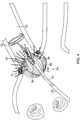
- FIG. 1 is a schematic illustration of an invasive medical procedure using apparatus 12, according to an embodiment of the present invention.
- the procedure is performed by a medical professional 14, and, by way of example, the procedure in the description hereinbelow is assumed to comprise ablation of a portion of a myocardium 16 of the heart of a human patient 18.
- embodiments of the present invention are not merely applicable to this specific procedure, and may include substantially any procedure on biological tissue or on non-biological materials.
- medical professional 14 inserts a probe 20 into a sheath 21 that has been pre-positioned in a lumen of the patient.
- Sheath 21 is positioned so that a distal end 22 of probe 20 enters the heart of the patient.
- a balloon catheter 24, which is described in more detail below with reference to FIG. 2 is deployed through a lumen 23 of the probe 20, and exits from a distal end of the probe 20.
- apparatus 12 is controlled by a system processor 46, which is located in an operating console 15 of the apparatus.
- Console 15 comprises controls 49 which are used by professional 14 to communicate with the processor.
- the processor 46 typically tracks a location and an orientation of the distal end 22 of the probe 20, using any method known in the art.
- processor 46 may use a magnetic tracking method, wherein magnetic transmitters 25X, 25Y and 25Z external to the patient 18 generate signals in coils positioned in the distal end of the probe 20.
- the software for the processor 46 may be downloaded to the processor in electronic form, over a network, for example. Alternatively or additionally, the software may be provided on non-transitory tangible media, such as optical, magnetic, or electronic storage media.
- the tracking of the distal end 22 is typically displayed on a three-dimensional representation 60 of the heart of the patient 18 on a screen 62.
- the processor 46 communicates with a memory 50, which has a number of modules used by the processor to operate the apparatus.
- the memory 50 comprises a temperature module 52, an ablation module 54, and an electrocardiograph (ECG) module 56, the functions of which are described below.
- the memory 50 typically comprises other modules, such as a force module for measuring the force on the distal end 22, a tracking module for operating the tracking method used by the processor 46, and an irrigation module allowing the processor to control irrigation provided for the distal end 22.
- the modules may comprise hardware as well as software elements.
- FIG. 3 is a schematic perspective view of the balloon catheter 24 in its inflated configuration, according to an embodiment of the present invention.
- the balloon catheter 24 is supported by a tubular shaft 70 having a proximal shaft portion 82 and a distal shaft end 88.
- the shaft 70 comprises a hollow central tube 74, which permits a catheter to pass therethrough and past the distal shaft end 88.
- the catheter may be a focal linear catheter or a lasso catheter 72, as illustrated.
- the lasso catheter 72 may be inserted into the pulmonary vein to position the balloon catheter 24 correctly with respect to the ostium prior to ablation of the ostium.
- the distal lasso portion of the catheter 72 is typically formed of shape-memory retentive material such as nitinol.
- the balloon catheter 24 may also be used with a linear or focal catheter 99 (as shown in broken lines in FIG. 3 ) in the PV or elsewhere in the heart.
- the focal catheter 99 may include a force sensor at its distal tip. Suitable force sending distal tips are disclosed in U.S. Patent No. 8,357,152, issued on January 22, 2013 to Govari et al. , titled CATHETER WITH PRESSURE SENSING, and in U.S.
- Any catheter used in conjunction with the balloon catheter may have features and functions, including, for example, pressure sensing, ablation, diagnostic, e.g., navigation and pacing.
- the inflatable balloon 80 of the balloon catheter 24 has an exterior wall or membrane 26 of a bio-compatible material, for example, formed from a plastic such as polyethylene terephthalate (PET), polyurethane or PEBAX®.
- the shaft 70 and the distal shaft end 88 define a longitudinal axis 78 of the balloon 80.
- the balloon 80 is deployed, in a collapsed uninflated configuration, via the lumen 23 of the probe 20, and may be inflated after existing from the distal end 22.
- the balloon 80 may be inflated and deflated by injection and expulsion of a fluid such as saline solution through the shaft 70.
- the membrane 26 of the balloon 80 is formed with irrigation pores or apertures 27 (shown in FIG.
- FIG. 6 shows fluid exiting the balloon 80 as jet streams, it is understood that the fluid may exit the balloon with any desired flow rate and/or pressure, including a rate where the fluid is seeping out of the balloon.
- the membrane 26 supports and carries a combined electrode and temperature sensing member which is constructed as a multi-layer flexible circuit electrode assembly 84.
- the "flex circuit electrode assembly” 84 may have many different geometric configurations.
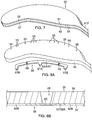
- the flex circuit electrode assembly 84 has a plurality of radiating leaves or strips 30, as best seen in FIG. 5 .
- the leaves 30 are evenly distributed about the distal end 88 and the balloon 80. Each leaf has wider proximal portion that gradually tapers to a narrower distal portion.
- each leaf 30 has a proximal tail 31P and a distal tail 31D.
- the proximal tail 31 P is tucked under and fastened to the catheter 24 by a proximal ring 28P mounted on the proximal shaft portion 82 of the shaft 70.
- the distal tail 31D is tucked under and fastened to the catheter 24 by a distal ring (not shown).
- Either or both sets of tails 31D and 31P may be further covered by a respective semispherical cap, such as distal cap 28D.
- One or more contact electrodes 33 on each leaf come into galvanic contract with the ostium 11 during an ablation procedure, during which electrical current flows from the contact electrodes 33 to the ostium 11, as shown in FIG. 4 .
- the flex circuit electrode assembly 84 includes a flexible and resilient sheet substrate 34, constructed of a suitable bio-compatible materials, for example, polyimide.
- the sheet substrate 34 has a greater heat resistance (or a higher melting temperature) compared to that of the balloon membrane 26.
- the substrate 34 is constructed of a thermoset material having a decomposition temperature that is higher than the melting temperature of the balloon membrane 26 by approximately 100C or more.
- the substrate 34 is formed with one or more irrigation pores or apertures 35 that are in alignment with the irrigation apertures 35 of the balloon member 26 so that fluid passing through the irrigation apertures 35 can pass to the ablation site on the ostium.
- the substrate 34 has a first or outer surface 36 facing away from the balloon membrane 26, and a second or inner surface 37 facing the balloon membrane 26. On its outer surface 36, the substrate 34 supports and carries the contact electrodes 33 adapted for tissue contact with the ostium. On its inner surface 37, the substrate 34 supports and carries a wiring electrode 38.
- the contact electrode 33 delivers RF energy to the ostium during ablation and/or is connected to a thermocouple junction for temperature sensing of the ostium.
- the contact electrode 33 has a longitudinally elongated portion 40 and a plurality of thin transversal linear portions or fingers 41 extending generally perpendicularly from each lateral side of the elongated portion 40 between enlarged proximal and distal ends 42P and 42D, generally evenly spaced therebetween.
- the elongated portion 40 has a greater width and each of the fingers has a generally uniform lesser width.
- the configuration or trace of the contact electrode 33 resembles a "fishbone.”
- the fingers 41 of the contact electrode 33 advantageously increase the circumferential or equatorial contact surface of the contact electrode 33 with the ostium while void regions 43 between adjacent fingers 41 advantageously allow the balloon 80 to collapse inwardly and/or expand radially as needed at locations along its equator.
- the fingers 41 have different lengths, some being longer, others being shorter
- the plurality of fingers include a distal finger, a proximal finger and fingers therebetween, where each of the fingers in between has a shorter adjacent finger.
- each finger has a length different from its distal and/or proximal immediately adjacent neighboring finger(s) such that the length of each finger generally follows the tapered configuration of each leaf 30.
- there are 22 fingers extending across (past each lateral side of) the elongated portion 40, with the longest finger being the third finger from the enlarged proximal end 42P.
- the contact electrode 33 includes gold 58B with a seed layer 45, between the gold 58B and the membrane 26 (see FIG. 12A and FIG. 12B ).
- the seed layer may include titanium, tungsten, palladium, silver, and/or combinations thereof.
- exclusion zone 47 Formed within the contact electrode 33 are one or more exclusion zone 47, each surrounding an irrigation aperture 27 formed in the substrate 26.
- the exclusion zones 47 are voids purposefully formed in the contact electrode 33, as explained in detail further below, so as to avoid damage to the contact electrode 33 during construction of the electrode assembly 84 in accommodating the irrigation apertures 27 at their locations and in their function.
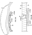
- conductive blind vias 48 are conductive or metallic formations that extend through through-holes 55, as shown in FIG. 8A , in the substrate 34 and are configured as electrical conduits connecting the contact electrode 33 on the outer surface 36 and the wiring electrode 38 on the inner surface 37. It is understood that “conductive” is used herein interchangeably with “metallic” in all relevant instances.
- the contact electrode 33 measures longitudinally between about 0.1 inch and 1.0 inch , and preferably between about 0.5 inch and 0.7 inch, and more preferably about 0.57 inch, and has four exclusion zones 47 and nine blind vias 48.
- the wiring electrode 38 is generally configured as an elongated body generally similar in shape and size to the elongated portion 40 of the contact electrode 33.
- the wiring electrode 38 loosely resembles a "spine" and also functions as a spine in terms of providing a predetermined degree of longitudinal rigidity to each leaf 30 of the electrode assembly 84.
- the wiring electrode 38 is positioned such that each of the blind vias 48 is in conductive contact with both the contact electrode 33 and the wiring electrode 38.
- the two electrodes 33 and 38 are in longitudinal alignment with other, with all nine blind vias 48 in conductive contact with both electrodes 33 and 38.
- the wiring electrode 38 has an inner portion of copper 57 and an outer portion of gold 58.
- the wiring electrode 38 is also formed with its exclusion zones 59 around the irrigation apertures 35 in the substrate 34.
- the wiring electrode 38 is further formed with solder pad portions 61, at least one active 61A, and there may be one or more inactive solder pad portions 61B.
- the solder pad portions 61A and 61B are extensions from a lateral side of the elongated body of the wiring electrode 38.
- an active solder pad portion 61A is formed at about a mid-location along the elongated body, and a respective inactive solder pad portion 61B is provided at each of the enlarged distal end 42D and the enlarged proximal end 42P.
- Attached, e.g., by a solder weld 63, to the active solder pad portion 61A are the wire pair, e.g., a constantan wire 51 and a copper wire 53.
- the copper wire 53 provides a lead wire to the wiring electrode 33, and the copper wire 53 and the constantan wire 51 provide a thermocouple whose junction is at solder weld 63.
- the wire pair 51/53 are passed through a through-hole 29 formed in the membrane 26.
- the wire pair 51/53 may run between the membrane 26 and the substrate 34 and further proximally between the membrane 26 and the proximal tail 31P until the wire pair 51/53 enters the tubular shaft 70 via another through-hole (not shown) formed in the tubular shaft sidewall closer to the proximal ring 28.
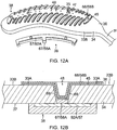
- the flex circuit electrode assembly 84 including the leaves 30 and the tails 31P and 31D, is affixed to the balloon membrane 26 such that the outer surface 36 of the substrate 34 is exposed and the inner surface 37 of the substrate 34 is affixed to the balloon membrane 26, with the wiring electrode 38 and wire pair 51/53 sandwiched between the substrate 34 and the balloon membrane 26.
- the irrigation apertures 35 in the substrate 34 are aligned with the irrigation apertures 27 in the balloon membrane 26.
- the exclusion zones 59 in the wiring electrode 38 and the exclusion zones 47 in the contact electrode 33 are concentrically aligned with each other, as well as with the irrigation apertures 27 and 35, as shown in FIG. 14 .
- the present invention includes methods of constructing the flex circuit electrode assembly, and a balloon with the flex circuit electrode assembly.
- the methods include the following Actions 1 - 9. It is understood that the Actions need not be taken in the sequence shown below, as desired or appropriate.
- Actions 1 In forming a flex circuit electrode assembly, providing a flex circuit having a substrate, a first conductive layer and a second conductive layer. 2 Removing the first conductive layer to expose a first surface of the substrate. 3 Forming the wiring electrode in the second conductive layer; the forming may include forming an exclusion zone, active solder pad, and/or inactive solder pad. 4 Forming through-holes in the substrate to provide one or more blind vias and one or more irrigation apertures.
- a flex circuit 90 having a flexible substrate 34 whose first or outer surface 36 is generally covered with a first conductive layer 91 and whose second or inner surface 37 is generally covered with a second conductive layer 92, as shown in FIG. 7.
- the substrate 34 is constructed of polyimide and the first and second conductive layers 91 and 92 are copper.
- the first conductive layer 91 of copper is removed from the outer surface 36 of the substrate 34 by chemical etching to expose the outer surface of the substrate.
- Forming the wiring electrode 38 may include forming the elongated body with at least an exclusion zone 59. Forming the wiring electrode 38 may include forming at least one active solder pad 61A. Forming the wiring electrode 38 may include forming at least one inactive solder pad 61B capable of functioning as a visual radiopaque marker.
- forming the wiring electrode 38 includes masking a configuration of the elongated body in a first portion 92A of the second conductive layer 92, with one or more solder pads, while leaving unmasked a second portion 92B and one or more exclusion zones 59 in the first portion 92A; and removing the second conductive layer 92B in the unmasked one or more exclusion zones 59 and the second portion 92B from the inner surface 37 of the substrate 34 by chemical etching.
- forming a through-hole 55 and/or the irrigation aperture 35 includes laser drilling through the substrate 34 from a direction facing the outer surface 36, at location within a perimeter trace 66 (shown in broken lines in FIG. 10 ) of the contact electrode 33 and to a depth through the entire thickness of substrate 34.
- the laser drilling is performed generally without penetrating the wiring electrode 38.
- the substrate 34 with the wiring electrode 38 being formed is immersed in a gold plating bath to form a gold layer 58A covering exposed conductive surfaces of the elongated body of the wiring electrode 38 and a bottom surface 65 of any and all blind vias 48.
- forming the contact electrode 33 includes (i) defining a first region 33A within a perimeter trace 66 in a configuration of the fishbone (including the elongated body 40 and the fingers 41) on the outer surface 36 of the substrate 34, as shown in FIG. 10 , (ii) applying photoresist 39 to a second region 33B outside of the first region 33A on the outer layer 36 of the substrate 34, as shown in FIG. 11B , (iii) applying a seed layer 45 onto the outer surface 36 of the substrate 34 in at least the first region 33A, as shown in FIG. 11A and FIG.
- applying photoresist 39 includes applying photoresist 39 to one or more exclusion zones 47 in the elongated portion 40 of the contact electrode 33 surrounding an irrigation aperture 35 formed in the substrate 34.
- applying a seed layer 45 includes sputtering the seed layer 45 to inside the one or more blind vias 48.
- applying the conductive layer 68 includes sputtering the conductive layer 68 to inside the one or more blind vias 48.
- the blind vias are formed with sloping or tapered sidewalls 69 (see FIG. 12B ) which are covered with the seed layer 45 and the conductive layer 68/58B.
- the substrate 34 inclusive of the electrodes 33 and 38 is immersed again in a gold plating bath to form another gold layer 58C covering exposed conductive surfaces of the electrode 33 and 38 and all blind vias 48.
- radiopaque markers 73 are applied or painted onto the gold layer 58C covering the wiring electrode 38.
- a mixture comprising tungsten and epoxy can be painted onto the gold layer 58C on the wiring electrode 38 to serve as radiopaque markers.
- the Actions 1-7 described above form the electrodes 33 and 38 on the substrate 34 in forming a flex circuit electrode assembly 84 which may then be prepared for affixation to a balloon membrane 26.
- the wire pair 51/53 are soldered to the active solder pad 61A, wherein the wire pair 51/53 function as a thermocouple, and the copper wire 53 functions as a lead wire delivering RF energy to the wiring electrode 38 which in turn energizes the contact electrode 33.
- peripheral regions 34P of the substrate 34 are formed with a plurality of perforations 75 configured to receive an adhesive for affixing the electrode assembly 84 to the balloon membrane 26.
- the wire pair 51/53 are fed through a through-hole 29 formed in the membrane 26 of and an adhesive (not shown) is applied to generally the entire inner surface 37 of the substrate 34, inclusive of the wiring electrode 38, to adhere the flex circuit electrode assembly 84 to the membrane 26.
- forming the contact electrode in the configuration of a "fishbone” may include sputtering the seed layer and the second added conductive layer directly on the balloon membrane, thus eliminating the use of a substrate and a wiring electrode.
- Appropriate wiring may be provided in the configurations described herein and/or with similar blind vias, full vias (i.e., that pass through the contact electrode, the substrate, the wiring electode, the contact microelectrode, and/or the wiring microelectrode), conductive traces, etc., as understood by one of ordinary skill in the art.
- Such a balloon catheter would nonetheless offer all the advantages afforded by a "fishbone" contact electrode, as described herein.
- a flex circuit electrode assembly 184 includes one or more contact microelectrodes 101 and wiring microelectrodes 102 physically and electrically isolated from contact electrode 133 and wiring electrode 138, respectively. Pairs of aligned contact microelectrode 101 and wiring electrode 102 are conductively connected to each other by a blind via 148. The one or more microelectrodes 101 and 102 are formed concurrently with the formation of the respective electrode 133 and 138 per the aforementioned Actions.
- the microelectrodes 101 and 102 are positioned near a midpoint along the length of the electrodes 133 and 138, so that the microelectrodes 101 and 102 are near the equatorial region of the balloon 80, although it is understood that they may be located at other locations relative to the electrodes 133 and 138.
- the microelectrodes 101 and 103 are configured for impedance, electrical signals, and/or temperature sensing independently of the electrodes 133 and 138 and thus are physically and electrically isolated from the contact electrode 133 and the wiring electrode 138, respectively by one or more respective exclusion zones 103 and 104.
- the wiring microelectrodes 102 For forming the wiring microelectrodes 102, for example, photoresist is applied to outer surface 136 of substrate 134 where the exclusion zones 103 are to be formed.
- the wiring microelectrodes 102 are formed with protrusions 107 that project into conforming recesses 108 formed in elongated body of the wiring electrode 138. Spanning between the protrusions 107 and the recesses 108, the exclusion zones 104 adopt a conforming configuration between the wiring electrode 138 and the wiring microelectrode 102.
- the contact microelectrodes 101 are formed by appropriately masking a second conductive layer 192 (not shown) on inner surface 137 of the substrate 134 in the configuration of the contact microelectrodes 101.
- the contact microelectrodes 101 are masked with protrusions 105 projecting into recesses 106 formed in elongated portion 140 of the contact electrode 133. Spanning between the protrusions 105 and the recesses 106, the exclusion zones 103 adopt a conforming configuration between the contact electrode 133 and the electrode 133 and the contact microelectrode 101.
- the protrusions 105 and 107 allow the microelectrodes 101 and 102 to be as close as possible to the contact and wiring electrodes 133 and 138 and hence as close as possible to the tissue contact site, while maintaining physical and electrical isolation,
- Wire pair 151/153 are soldered to active solder pad 161A.
- a lead wire (e.g., copper wires) 109 is soldered to a respective wiring microelectrode 102.
- the wires 151, 153 and 109 are part of a ribbon cable 110 that extends through through-hole 129 formed in balloon membrane 126.
- the wiring electrode 138 is shown as a "split" electrode comprising a first or distal elongated portion 138A and a second or proximal elongated portion 138B.
- the second wiring electrode portion 138B may function as a radiopaque marker with an enlarged portion 112 on one lateral side as a visual indicator under fluoroscopy of, for example, a specific wiring electrode, such as a "first" wiring electrode, and/or a direction toward subsequently numbered wiring electrodes around the circumference of balloon 180.
- the second wiring electrode portion 138B may also beactive where respective lead wires are connected thereto to deliver RF energy to it.
- a plurality of active wiring electrodes may each have its own copper wire while sharing a common constantan wire.
- such wire pairs may provide both RF energizing functions and temperature sensing functions.
- the contact electrode 133 it may also be split into contact electrode portions 133A and 133B, as shown in FIG. 17 , in correspondence with the split wiring electrode portions 138A and 138B, where the contact electrode portion 133A is conductively connected by blind vias 148A to the wiring electrode portion 138A, and contact electrode portion 133B is conductively connected by blind vias 148B to wiring electrode portion 138B.
- microelectrodes 101 and 102 may also be formed as "islands" (of any suitable shape and size), each surrounded in its entirety by the exclusion zones 106 and 107, respectively, formed in the electrodes 133 and 138 (in full, or in split electrode portions), respectively, as shown in FIG. 16A, FIG. 16B and FIG. 17 .
- a blind via 148 may be formed in each contact microelectrode 101 to provide a conductive connection with its wiring microelectrode 102.
- a full via 188 may be formed in each wiring microelectrode 102 as a conductive connection to its wire pair, which can enable the microelectrodes 101 and 102 for ablation, electropotential, sensing, impedance detection and/or temperature sensing.
- FIG. 18A illustrates a thermocouple 400 formed from a copper conductor or wire 476 connected to a constantan conductor or wire 477 by a conducting via 481.
- the wires 476 and 477 are formed as conducting lines embedded in substrate 424.
- the via 481 also connects to a contact microelectrode 401 on the outer surface of the substrate.
- the wires 476 and 477 exit at solder pads 463a and 463b, respectively, which are located remotely from the microelectrode 401, in a region of the proximal tail 31P, for example, near its tip end.
- the potential between the solder pads 463a and 463b comprises a signal to the temperature module 52 in the console 15 ( FIG. 1 ), and the module uses the signal to formulate the temperature measured by the thermocouple 400 at the location of the microelectrode 401.
- solder pad 463a connected to the copper wire 476 and/or the solder pad 463b connected to the constantan wire 477 may also be used to acquire electropotentials formed on the microelectrode 401 that the solder pad is connected to by via 481.
- the ECG module 56 of the console 15 typically receives signals derived from the solder pads 463a and/or 463b, and analyzes the signals to derive the electropotentials at the microelectrode 401.
- a solder pad 463c is connected, via another conducting wire embedded in substrate 434, to contact electrode 433 and the solder pad 463c may be used to transfer electromagnetic RF ablation energy, generated by the ablation module 54 of the console 15 ( FIG. 1 ), to the contact electrode 433.
- the solder pads 463c, 463a and 463b may be grouped as a set of three solder pads 463G(1) connecting to the contact electrode 433, the microelectrode 401 and the thermocouple 400.
- a set of three pads 463G(i) may be connected to a set of contact electrode, microelectrode and thermocouple.
- the location of at least the solder pads 463a and 463b can be advantageously remote from the location of where the temperature is measured, so that any bulkiness embodied in the solder pads 463a and 463b can be avoided at location of the microelectrode 401 where tissue contact occurs.
- irrigation apertures 127 are formed in the balloon membrane 126
- irrigation apertures 135 are formed in the substrate 134
- exclusion zones 147 are formed in the contact electrode 133
- exclusion zones 159 are formed in the wiring electrode 138.
- the substrate 34, 134 (e.g., polyimide) has a thickness of about 25.0 microns.
- the wiring electrode 38, 138 includes an inner layer of copper having a thickness of about 2.0 microns and an outer layer of gold of having a thickness of ranging between about 1.0 and 50 microns, and preferably between about 2.75 microns and 37 microns, where the thickness of the gold depends on how much radiopacity is desired or appropriate.
- the contact electrode 33, 133 includes a seed layer having a thickness of about 0.01 - 0.05 microns and an outer layer of gold having a thickness of about 1.0 micron.
- the balloon membrane 26, 126 may have an average thickness of about 25.0 microns as it understood that the membrane may have a nonuniform thickness due to the method of manufacture.
- the wire pair 51/53 conduct RF energy provided by the ablation module 54 of the console 15 ( FIG. 1 ) through the control handle and the catheter shaft to the wiring electrode 38 which in turn energizes the contact electrode 33 through the blind vias 48.
- 10 functionally satisfactory lesions can be generated by discharging 25W of RF power through each of the contact electrode 33 simultaneously, i.e., for a total of 250W, for ten seconds or less.
- suitable ranges of power supplied to each contact electrode include between about 15-25W for 10 seconds and 10-20W for 60 seconds. In other embodiments, the power supplied to each contact electrode is at 25W or higher for ten seconds or less.
Priority Applications (1)
| Application Number | Priority Date | Filing Date | Title |
|---|---|---|---|
| EP23168043.0A EP4230164A1 (fr) | 2016-04-28 | 2017-04-27 | Cathéter à ballonnet irrigué avec ensemble d'électrodes de circuit flexible |
Applications Claiming Priority (4)
| Application Number | Priority Date | Filing Date | Title |
|---|---|---|---|
| US15/141,751 US10638976B2 (en) | 2016-04-28 | 2016-04-28 | Method of constructing irrigated balloon catheter |
| US15/172,118 US20170347896A1 (en) | 2016-06-02 | 2016-06-02 | Balloon catheter and related impedance-based methods for detecting occlusion |
| US15/360,964 US10653480B2 (en) | 2016-04-28 | 2016-11-23 | Method for constructing irrigated balloon catheter with flexible circuit electrode assembly |
| US15/360,966 US10660700B2 (en) | 2016-04-28 | 2016-11-23 | Irrigated balloon catheter with flexible circuit electrode assembly |
Related Child Applications (1)
| Application Number | Title | Priority Date | Filing Date |
|---|---|---|---|
| EP23168043.0A Division EP4230164A1 (fr) | 2016-04-28 | 2017-04-27 | Cathéter à ballonnet irrigué avec ensemble d'électrodes de circuit flexible |
Publications (2)
| Publication Number | Publication Date |
|---|---|
| EP3238646A2 true EP3238646A2 (fr) | 2017-11-01 |
| EP3238646A3 EP3238646A3 (fr) | 2018-01-17 |
Family
ID=58638759
Family Applications (5)
| Application Number | Title | Priority Date | Filing Date |
|---|---|---|---|
| EP17168513.4A Active EP3238647B1 (fr) | 2016-04-28 | 2017-04-27 | Procédés de construction de cathéter à ballonnet irrigué au moyen d'un ensemble d'électrodes à circuit flexible |
| EP17201434.2A Active EP3300680B1 (fr) | 2016-04-28 | 2017-04-27 | Procédés de construction de cathéter à ballonnet irrigué au moyen d'un ensemble d'électrodes à circuit flexible |
| EP17168393.1A Ceased EP3238646A3 (fr) | 2016-04-28 | 2017-04-27 | Cathéter à ballonnet irrigué avec ensemble d'électrodes à circuit flexible |
| EP23168043.0A Pending EP4230164A1 (fr) | 2016-04-28 | 2017-04-27 | Cathéter à ballonnet irrigué avec ensemble d'électrodes de circuit flexible |
| EP20177696.0A Pending EP3861954A1 (fr) | 2016-04-28 | 2017-04-27 | Cathéter à ballonnet irrigué au moyen d'un ensemble électrodes à circuit flexible |
Family Applications Before (2)
| Application Number | Title | Priority Date | Filing Date |
|---|---|---|---|
| EP17168513.4A Active EP3238647B1 (fr) | 2016-04-28 | 2017-04-27 | Procédés de construction de cathéter à ballonnet irrigué au moyen d'un ensemble d'électrodes à circuit flexible |
| EP17201434.2A Active EP3300680B1 (fr) | 2016-04-28 | 2017-04-27 | Procédés de construction de cathéter à ballonnet irrigué au moyen d'un ensemble d'électrodes à circuit flexible |
Family Applications After (2)
| Application Number | Title | Priority Date | Filing Date |
|---|---|---|---|
| EP23168043.0A Pending EP4230164A1 (fr) | 2016-04-28 | 2017-04-27 | Cathéter à ballonnet irrigué avec ensemble d'électrodes de circuit flexible |
| EP20177696.0A Pending EP3861954A1 (fr) | 2016-04-28 | 2017-04-27 | Cathéter à ballonnet irrigué au moyen d'un ensemble électrodes à circuit flexible |
Country Status (10)
| Country | Link |
|---|---|
| US (3) | US10660700B2 (fr) |
| EP (5) | EP3238647B1 (fr) |
| JP (2) | JP6949542B2 (fr) |
| CN (2) | CN107361840B (fr) |
| AU (2) | AU2017202466A1 (fr) |
| CA (2) | CA2963527A1 (fr) |
| DK (1) | DK3238647T3 (fr) |
| ES (1) | ES2766602T3 (fr) |
| IL (3) | IL251716B (fr) |
| RU (2) | RU2017113694A (fr) |
Cited By (10)
| Publication number | Priority date | Publication date | Assignee | Title |
|---|---|---|---|---|
| WO2019023280A1 (fr) * | 2017-07-25 | 2019-01-31 | Affera, Inc. | Cathéters d'ablation et systèmes et procédés associés |
| EP3572024A1 (fr) * | 2018-05-25 | 2019-11-27 | Biosense Webster (Israel) Ltd. | Transfert de chaleur amélioré par l'intermédiaire d'une pointe de cathéter |
| EP3574954A3 (fr) * | 2018-05-30 | 2019-12-11 | Biosense Webster (Israel) Ltd. | Cathéter à ballonnet de grand diamètre amélioré |
| US11498108B2 (en) | 2019-09-02 | 2022-11-15 | Toyota Jidosha Kabushiki Kaisha | Manufacturing apparatus and manufacturing method for hat-shaped cross-section component |
| EP4201355A1 (fr) * | 2021-12-23 | 2023-06-28 | Biosense Webster (Israel) Ltd | Couvercle pour électrodes à circuit flexible d'un cathéter à ballonnet d'électrophysiologie |
| EP4205678A1 (fr) * | 2021-12-29 | 2023-07-05 | Biosense Webster (Israel) Ltd. | Ballonnet de cathéter présentant une résilience accrue à la mise sous pression interne |
| US11712294B2 (en) | 2018-05-25 | 2023-08-01 | Biosense Webster (Israel) Ltd. | Heat transfer through a catheter tip |
| US11751937B2 (en) | 2017-07-25 | 2023-09-12 | Affera, Inc. | Ablation catheters and related systems and methods |
| US11957852B2 (en) | 2021-01-14 | 2024-04-16 | Biosense Webster (Israel) Ltd. | Intravascular balloon with slidable central irrigation tube |
| US11963715B2 (en) | 2016-11-23 | 2024-04-23 | Biosense Webster (Israel) Ltd. | Balloon-in-balloon irrigation balloon catheter |
Families Citing this family (64)
| Publication number | Priority date | Publication date | Assignee | Title |
|---|---|---|---|---|
| WO2013086461A1 (fr) | 2011-12-09 | 2013-06-13 | Metavention, Inc. | Neuromodulation thérapeutique du système hépatique |
| US11534239B2 (en) | 2014-12-22 | 2022-12-27 | Biosense Webster (Israel) Ltd. | Systems and method or uses of ablating cardiac tissue |
| US10660700B2 (en) | 2016-04-28 | 2020-05-26 | Biosense Webster (Israel) Ltd. | Irrigated balloon catheter with flexible circuit electrode assembly |
| US10638976B2 (en) | 2016-04-28 | 2020-05-05 | Biosense Webster (Israel) Ltd | Method of constructing irrigated balloon catheter |
| US10524859B2 (en) | 2016-06-07 | 2020-01-07 | Metavention, Inc. | Therapeutic tissue modulation devices and methods |
| US20190175262A1 (en) * | 2017-12-11 | 2019-06-13 | Biosense Webster (Israel) Ltd. | Balloon catheter distal end comprising electrodes and thermocouples |
| US20190183567A1 (en) * | 2017-12-19 | 2019-06-20 | Biosense Webster (Israel) Ltd. | Balloon Catheter with Bulbous Shaped Radiofrequency (RF) Ablation Electrodes |
| US20190298441A1 (en) * | 2018-03-28 | 2019-10-03 | Biosense Webster (Israel) Ltd. | Irrigated electrophysiology catheter with distinguishable electrodes for multi-electrode identification and orientation under 2-d visualization |
| US11864825B2 (en) * | 2018-05-02 | 2024-01-09 | Biosense Webster (Israel) Ltd. | Ablation catheter with selective radial energy delivery |
| EP3768186B1 (fr) * | 2018-05-31 | 2022-09-14 | St. Jude Medical, Cardiology Division, Inc. | Poignée de cathéter avec circuit souple |
| US11779280B2 (en) | 2018-06-29 | 2023-10-10 | Biosense Webster (Israel) Ltd. | Reference wires to remove noise and artifacts in cardiac mapping catheter |
| US20200001054A1 (en) | 2018-06-29 | 2020-01-02 | Biosense Webster (Israel) Ltd. | Reinforcement for irrigated electrophysiology balloon catheter with flexible-circuit electrodes |
| US11642165B2 (en) | 2018-06-29 | 2023-05-09 | Biosense Webster (Israel) Ltd. | Catheter with mechanically expandable element having flex circuit |
| US20200030024A1 (en) * | 2018-07-30 | 2020-01-30 | Biosense Webster (Israel) Ltd. | Flexible-circuit tip for a split-tip catheter |
| US20200038101A1 (en) | 2018-08-03 | 2020-02-06 | Biosense Webster (Israel) Ltd. | Unipolar reference electrode for electrophysiology mapping catheter |
| US11737818B2 (en) * | 2018-08-14 | 2023-08-29 | Biosense Webster (Israel) Ltd. | Heat transfer during ablation procedures |
| CN109009407A (zh) * | 2018-09-10 | 2018-12-18 | 科塞尔医疗科技(苏州)有限公司 | 可实现标测功能的冷冻消融球囊导管及方法 |
| WO2020053831A1 (fr) | 2018-09-14 | 2020-03-19 | Biosense Webster (Israel) Ltd. | Systèmes d'ablation de tissu cardiaque |
| CN113164200A (zh) | 2018-09-14 | 2021-07-23 | 伯恩森斯韦伯斯特(以色列)有限责任公司 | 消融心脏组织的系统和方法或用途 |
| US11071585B2 (en) | 2018-09-14 | 2021-07-27 | Biosense Webster (Israel) Ltd. | Systems and methods of ablating cardiac tissue |
| US20200138512A1 (en) | 2018-11-06 | 2020-05-07 | Biosense Webster (Israel) Ltd. | Attaining Higher Impedances for Large Indifferent Electrodes |
| US11717344B2 (en) | 2018-11-19 | 2023-08-08 | Biosense Webster (Israel) Ltd. | Medical probe with wiring disposed between two expandable membranes |
| US11751936B2 (en) * | 2018-11-21 | 2023-09-12 | Biosense Webster (Israel) Ltd. | Configuring perimeter of balloon electrode as location sensor |
| WO2020104888A1 (fr) | 2018-11-21 | 2020-05-28 | Biosense Webster (Israel) Ltd. | Cathéter d'ablation avec ensemble circuit empilé |
| US20200205737A1 (en) * | 2018-12-28 | 2020-07-02 | Biosense Webster (Israel) Ltd. | Flexible Nested Sensing Electrodes |
| USD968421S1 (en) | 2019-05-31 | 2022-11-01 | Biosense Webster (Israel) Ltd. | Display screen with a graphical user interface |
| USD968422S1 (en) | 2019-05-31 | 2022-11-01 | Biosense Webster (Israel) Ltd. | Display screen with transitional graphical user interface |
| USD969138S1 (en) | 2019-05-31 | 2022-11-08 | Biosense Webster (Israel) Ltd. | Display screen with a graphical user interface |
| US11744480B2 (en) | 2019-06-25 | 2023-09-05 | Biosense Webster (Israel) Ltd. | Catheter deflection system with deflection load limiter |
| US20200405385A1 (en) | 2019-06-25 | 2020-12-31 | Biosense Webster (Israel) Ltd. | Irrigation fluid monitor and alarm |
| US20210004145A1 (en) * | 2019-07-01 | 2021-01-07 | Biosense Webster (Israel) Ltd. | Ablation system with graphical user interface |
| US20210001083A1 (en) * | 2019-07-03 | 2021-01-07 | Biosense Webster (Israel) Ltd. | Sensing and mapping catheter for guiding and supporting balloon catheter |
| US20210001084A1 (en) * | 2019-07-03 | 2021-01-07 | Biosense Webster (Israel) Ltd. | Composite catheter with single axial sensors and ring electrodes and related methods |
| US11540878B2 (en) | 2019-07-17 | 2023-01-03 | Biosense Webster (Israel) Ltd. | Blooming leaflet catheter with high density electrode array |
| US20210059744A1 (en) | 2019-09-03 | 2021-03-04 | Biosense Webster (Israel) Ltd. | Catheter construction to eliminate static and noise |
| US20210059745A1 (en) | 2019-09-03 | 2021-03-04 | Biosense Webster (Israel) Ltd. | Mapping catheter with flex panel electrode assembly |
| US20210077184A1 (en) | 2019-09-16 | 2021-03-18 | Biosense Webster (Israel) Ltd. | Catheter with thin-film electrodes on expandable membrane |
| US11896395B2 (en) | 2019-09-17 | 2024-02-13 | Biosense Webster (Israel) Ltd. | Catheter with insert-molded microelectrode |
| US20210077183A1 (en) | 2019-09-18 | 2021-03-18 | Biosense Webster (Israel) Ltd. | Catheter with thin-film electrodes on expandable mechanical structure |
| US20210085386A1 (en) | 2019-09-20 | 2021-03-25 | Biosense Webster (Israel) Ltd. | Catheter instrument with three pull wires |
| US20210113812A1 (en) | 2019-10-22 | 2021-04-22 | Biosense Webster (Israel) Ltd. | Flared insert member for use with catheter assembly |
| US20210121231A1 (en) | 2019-10-23 | 2021-04-29 | Biosense Webster (Israel) Ltd. | Cardiac mapping catheter with square-spaced electrodes |
| US11918751B2 (en) | 2019-11-12 | 2024-03-05 | Biosense Webster (Israel) Ltd. | Catheter with vapor deposited features on tip |
| US20210169567A1 (en) * | 2019-12-09 | 2021-06-10 | Biosense Webster (Israel) Ltd. | Irreversible-electroporation (ire) balloon catheter with membrane-insulated high-voltage balloon wires |
| US20210177506A1 (en) | 2019-12-16 | 2021-06-17 | Biosense Webster (Israel) Ltd. | Catheter deflection control assembly |
| US11918282B2 (en) | 2020-04-17 | 2024-03-05 | Biosense Webster (Israel) Ltd. | Pressure relief feature for irrigated RF balloon catheter |
| JP2021186647A (ja) | 2020-05-29 | 2021-12-13 | バイオセンス・ウエブスター・(イスラエル)・リミテッドBiosense Webster (Israel), Ltd. | 不整脈を診断するための電極装置 |
| US20220104872A1 (en) | 2020-10-07 | 2022-04-07 | Biosense Webster (Israel) Ltd. | Printed Proximal Electrodes of an Expandable Catheter for Use as a Common Electrode |
| CN112353484B (zh) * | 2020-10-20 | 2022-02-25 | 上海交通大学 | 一种柔性微传感器系统、可延展柔性器件及制备方法 |
| US20220133402A1 (en) * | 2020-10-30 | 2022-05-05 | Biosense Webster (Israel) Ltd. | Balloon Catheter with Split Electrodes |
| CN112545643B (zh) * | 2021-02-23 | 2021-05-28 | 上海安钛克医疗科技有限公司 | 电极、球囊导管及消融系统 |
| CN113081239B (zh) * | 2021-03-31 | 2024-01-09 | 上海诺生医疗科技有限公司 | 笼状电极导管以及包括该笼状电极导管的消融设备 |
| CN113995501A (zh) * | 2021-05-25 | 2022-02-01 | 圣犹达医疗用品心脏病学部门有限公司 | 用于配设有网篮和球囊的电穿孔设备的系统和方法 |
| US20230054269A1 (en) * | 2021-08-23 | 2023-02-23 | Biosense Webster (Israel) Ltd. | Basket Catheter with Porous Sheath |
| US20230061561A1 (en) * | 2021-08-27 | 2023-03-02 | Biosense Webster (Israel) Ltd. | Reinforcement and stress relief for an irrigated electrophysiology balloon catheter with flexible-circuit electrodes |
| US20230181241A1 (en) | 2021-12-10 | 2023-06-15 | Biosense Webster (Israel) Ltd. | Electrical paths along flexible section of deflectable sheath |
| US20230190367A1 (en) | 2021-12-17 | 2023-06-22 | Biosense Webster (Israel) Ltd. | Catheter end effector with laterally projecting body |
| US20230200895A1 (en) | 2021-12-27 | 2023-06-29 | Biosense Webster (Israel) Ltd. | Catheter end effector with resilient frame and flexible interior |
| US20230210592A1 (en) | 2021-12-30 | 2023-07-06 | Biosense Webster (Israel) Ltd. | Dual balloons for pulmonary vein isolation |
| WO2023167125A1 (fr) * | 2022-03-01 | 2023-09-07 | テルモ株式会社 | Dispositif médical |
| US20230310071A1 (en) | 2022-04-05 | 2023-10-05 | Biosense Webster (Israel) Ltd. | Catheter with external magnetic coils |
| US20240091502A1 (en) | 2022-09-20 | 2024-03-21 | Biosense Webster (Israel) Ltd. | Catheter shaft with multi-plane articulation and rotation |
| US20240099768A1 (en) | 2022-09-22 | 2024-03-28 | Biosense Webster (Israel) Ltd. | Two-segment deflectin catheter with side exit guidwire lumen |
| US20240123210A1 (en) | 2022-10-18 | 2024-04-18 | Biosense Webster (Israel) Ltd. | Catheter insertion tool |
Citations (7)
| Publication number | Priority date | Publication date | Assignee | Title |
|---|---|---|---|---|
| US6012457A (en) | 1997-07-08 | 2000-01-11 | The Regents Of The University Of California | Device and method for forming a circumferential conduction block in a pulmonary vein |
| US6024740A (en) | 1997-07-08 | 2000-02-15 | The Regents Of The University Of California | Circumferential ablation device assembly |
| US6814733B2 (en) | 2002-01-31 | 2004-11-09 | Biosense, Inc. | Radio frequency pulmonary vein isolation |
| US7340307B2 (en) | 1997-07-08 | 2008-03-04 | Atrionix, Inc. | Tissue ablation device assembly and method for electrically isolating a pulmonary vein ostium from an atrial wall |
| US20110130648A1 (en) | 2009-11-30 | 2011-06-02 | Christopher Thomas Beeckler | Catheter with pressure measuring tip |
| US8357152B2 (en) | 2007-10-08 | 2013-01-22 | Biosense Webster (Israel), Ltd. | Catheter with pressure sensing |
| US20160175041A1 (en) | 2014-12-22 | 2016-06-23 | Biosense Webster (Israel) Ltd. | Balloon for ablation around pulmonary veins |
Family Cites Families (98)
| Publication number | Priority date | Publication date | Assignee | Title |
|---|---|---|---|---|
| FR1344459A (fr) | 1962-10-18 | 1963-11-29 | Procédé et appareil pour l'étude électrique des organismes vivants | |
| US4232676A (en) * | 1978-11-16 | 1980-11-11 | Corning Glass Works | Surgical cutting instrument |
| US4587975A (en) | 1984-07-02 | 1986-05-13 | Cardiac Pacemakers, Inc. | Dimension sensitive angioplasty catheter |
| EP0249823B1 (fr) | 1986-06-16 | 1991-12-18 | Pacesetter AB | Dispositif pour le contrôle d'un stimulateur cardiaque intracorporel utilisant la mesure de l'impedance de tissus corporels |
| US5178957A (en) | 1989-05-02 | 1993-01-12 | Minnesota Mining And Manufacturing Company | Noble metal-polymer composites and flexible thin-film conductors prepared therefrom |
| US20020002369A1 (en) | 1993-08-23 | 2002-01-03 | Hood Larry L. | Method and apparatus for modifying visual acuity by moving a focal point of energy within a cornea |
| US5797903A (en) * | 1996-04-12 | 1998-08-25 | Ep Technologies, Inc. | Tissue heating and ablation systems and methods using porous electrode structures with electrically conductive surfaces |
| US5584830A (en) | 1994-03-30 | 1996-12-17 | Medtronic Cardiorhythm | Method and system for radiofrequency ablation of cardiac tissue |
| CA2194071C (fr) | 1994-06-27 | 2005-12-13 | Roger A. Stern | Systemes et procedes de commande non lineaire permettant de chauffer des tissus humains et pratiquer leur ablation |
| NL1001890C2 (nl) | 1995-12-13 | 1997-06-17 | Cordis Europ | Catheter met plaatvormige elektrode-reeks. |
| WO1997025917A1 (fr) | 1996-01-19 | 1997-07-24 | Ep Technologies, Inc. | Structures multifonctionnelles d'electrodes destinees a l'analyse et au chauffage electriques de tissus corporels |
| US6719755B2 (en) | 1996-10-22 | 2004-04-13 | Epicor Medical, Inc. | Methods and devices for ablation |
| US5971983A (en) | 1997-05-09 | 1999-10-26 | The Regents Of The University Of California | Tissue ablation device and method of use |
| US6164283A (en) | 1997-07-08 | 2000-12-26 | The Regents Of The University Of California | Device and method for forming a circumferential conduction block in a pulmonary vein |
| US6966908B2 (en) | 1997-07-08 | 2005-11-22 | Atrionix, Inc. | Tissue ablation device assembly and method for electrically isolating a pulmonary vein ostium from an atrial wall |
| US6500174B1 (en) | 1997-07-08 | 2002-12-31 | Atrionix, Inc. | Circumferential ablation device assembly and methods of use and manufacture providing an ablative circumferential band along an expandable member |
| US6997925B2 (en) | 1997-07-08 | 2006-02-14 | Atrionx, Inc. | Tissue ablation device assembly and method for electrically isolating a pulmonary vein ostium from an atrial wall |
| JP3857788B2 (ja) | 1997-09-01 | 2006-12-13 | テルモ株式会社 | 循環器情報計測システム |
| US6042580A (en) | 1998-05-05 | 2000-03-28 | Cardiac Pacemakers, Inc. | Electrode having composition-matched, common-lead thermocouple wire for providing multiple temperature-sensitive junctions |
| US6522930B1 (en) | 1998-05-06 | 2003-02-18 | Atrionix, Inc. | Irrigated ablation device assembly |
| US6226542B1 (en) | 1998-07-24 | 2001-05-01 | Biosense, Inc. | Three-dimensional reconstruction of intrabody organs |
| US6301496B1 (en) | 1998-07-24 | 2001-10-09 | Biosense, Inc. | Vector mapping of three-dimensionally reconstructed intrabody organs and method of display |
| US6123718A (en) | 1998-11-02 | 2000-09-26 | Polymerex Medical Corp. | Balloon catheter |
| US6986744B1 (en) | 1999-02-02 | 2006-01-17 | Transonic Systems, Inc. | Method and apparatus for determining blood flow during a vascular corrective procedure |
| US6702811B2 (en) | 1999-04-05 | 2004-03-09 | Medtronic, Inc. | Ablation catheter assembly with radially decreasing helix and method of use |
| US6471693B1 (en) | 1999-09-10 | 2002-10-29 | Cryocath Technologies Inc. | Catheter and system for monitoring tissue contact |
| US7020400B2 (en) | 1999-12-24 | 2006-03-28 | Altera Corporation | Multi-wavelength optical communication system |
| US6892091B1 (en) | 2000-02-18 | 2005-05-10 | Biosense, Inc. | Catheter, method and apparatus for generating an electrical map of a chamber of the heart |
| US6546935B2 (en) | 2000-04-27 | 2003-04-15 | Atricure, Inc. | Method for transmural ablation |
| AU2001279026B2 (en) | 2000-07-25 | 2005-12-22 | Angiodynamics, Inc. | Apparatus for detecting and treating tumors using localized impedance measurement |
| US6997924B2 (en) | 2002-09-17 | 2006-02-14 | Biosense Inc. | Laser pulmonary vein isolation |
| US7156816B2 (en) | 2002-11-26 | 2007-01-02 | Biosense, Inc. | Ultrasound pulmonary vein isolation |
| JP2005052424A (ja) | 2003-08-05 | 2005-03-03 | Matsushita Electric Ind Co Ltd | 超音波診断装置 |
| US20050059862A1 (en) * | 2003-09-12 | 2005-03-17 | Scimed Life Systems, Inc. | Cannula with integrated imaging and optical capability |
| US7435248B2 (en) | 2003-09-26 | 2008-10-14 | Boston Scientific Scimed, Inc. | Medical probes for creating and diagnosing circumferential lesions within or around the ostium of a vessel |
| US9713730B2 (en) | 2004-09-10 | 2017-07-25 | Boston Scientific Scimed, Inc. | Apparatus and method for treatment of in-stent restenosis |
| US20060135953A1 (en) | 2004-12-22 | 2006-06-22 | Wlodzimierz Kania | Tissue ablation system including guidewire with sensing element |
| DE102005012739B4 (de) | 2005-03-19 | 2010-09-16 | MAX-PLANCK-Gesellschaft zur Förderung der Wissenschaften e.V. | Verfahren zur Herstellung räumlicher Feinstrukturen |
| US7442190B2 (en) | 2005-05-13 | 2008-10-28 | Cryocath Technologies Inc. | Contact assessment of balloon catheters |
| US7536218B2 (en) | 2005-07-15 | 2009-05-19 | Biosense Webster, Inc. | Hybrid magnetic-based and impedance-based position sensing |
| US7756576B2 (en) | 2005-08-26 | 2010-07-13 | Biosense Webster, Inc. | Position sensing and detection of skin impedance |
| CA2621657C (fr) | 2005-09-21 | 2014-06-17 | Surmodics, Inc. | Occlusion in situ utilisant des polysaccharides biodegradables naturels |
| US8696656B2 (en) | 2005-11-18 | 2014-04-15 | Medtronic Cryocath Lp | System and method for monitoring bioimpedance and respiration |
| US7842031B2 (en) | 2005-11-18 | 2010-11-30 | Medtronic Cryocath Lp | Bioimpedance measurement system and method |
| US20070287994A1 (en) | 2006-06-12 | 2007-12-13 | Pankaj Amrit Patel | Endoscopically Introducible Expandable Bipolar Probe |
| WO2008049087A2 (fr) | 2006-10-18 | 2008-04-24 | Minnow Medical, Inc. | Système pour induire des effets thermiques désirables sur un tissu anatomique |
| US8764742B2 (en) | 2007-04-04 | 2014-07-01 | St. Jude Medical, Atrial Fibrillation Division, Inc. | Irrigated catheter |
| US8641704B2 (en) | 2007-05-11 | 2014-02-04 | Medtronic Ablation Frontiers Llc | Ablation therapy system and method for treating continuous atrial fibrillation |
| JP2009089806A (ja) * | 2007-10-05 | 2009-04-30 | Asahi Intecc Co Ltd | バルーンカテーテル |
| US9289141B2 (en) | 2007-10-12 | 2016-03-22 | Micropen Technologies Corporation | Apparatus and methods for the measurement of cardiac output |
| US9101431B2 (en) | 2007-11-01 | 2015-08-11 | Stephen B. Murphy | Guide for acetabular component positioning |
| US9717501B2 (en) | 2007-11-21 | 2017-08-01 | St. Jude Medical, Atrial Fibrillation Division, Inc. | Methods and systems for occluding vessels during cardiac ablation including optional electroanatomical guidance |
| US9126023B1 (en) | 2007-12-14 | 2015-09-08 | Gmedelaware 2 Llc | Balloon expandable cement director and related methods |
| US8103327B2 (en) * | 2007-12-28 | 2012-01-24 | Rhythmia Medical, Inc. | Cardiac mapping catheter |
| DE102008062021A1 (de) | 2008-08-18 | 2010-03-04 | Epcos Ag | Piezoaktor in Vielschichtbauweise |
| US9545285B2 (en) | 2011-10-05 | 2017-01-17 | Mc10, Inc. | Cardiac catheter employing conformal electronics for mapping |
| PL2370015T3 (pl) | 2008-11-11 | 2017-07-31 | Shifamed Holdings, Llc | Niskoprofilowy zespół elektrodowy |
| US8805466B2 (en) | 2008-11-11 | 2014-08-12 | Shifamed Holdings, Llc | Low profile electrode assembly |
| US9795442B2 (en) | 2008-11-11 | 2017-10-24 | Shifamed Holdings, Llc | Ablation catheters |
| US20100160906A1 (en) * | 2008-12-23 | 2010-06-24 | Asthmatx, Inc. | Expandable energy delivery devices having flexible conductive elements and associated systems and methods |
| US8551096B2 (en) * | 2009-05-13 | 2013-10-08 | Boston Scientific Scimed, Inc. | Directional delivery of energy and bioactives |
| US20110295247A1 (en) | 2010-05-28 | 2011-12-01 | Hansen Medical, Inc. | System and method for automated minimally invasive therapy using radiometry |
| JP5615073B2 (ja) | 2010-07-20 | 2014-10-29 | オムロンヘルスケア株式会社 | 測定装置 |
| US9463062B2 (en) | 2010-07-30 | 2016-10-11 | Boston Scientific Scimed, Inc. | Cooled conductive balloon RF catheter for renal nerve ablation |
| ES2751156T3 (es) | 2010-10-20 | 2020-03-30 | Medtronic Ardian Luxembourg | Aparatos de catéter que tienen estructuras de malla expansibles para neuromodulación renal |
| US11246653B2 (en) | 2010-12-07 | 2022-02-15 | Boaz Avitall | Catheter systems for cardiac arrhythmia ablation |
| US20120191086A1 (en) | 2011-01-20 | 2012-07-26 | Hansen Medical, Inc. | System and method for endoluminal and translumenal therapy |
| US8974450B2 (en) * | 2011-02-03 | 2015-03-10 | Covidien Lp | System and method for ablation procedure monitoring using electrodes |
| US9757044B2 (en) | 2011-03-10 | 2017-09-12 | Acutus Medical, Inc. | Device and method for the geometric determination of electrical dipole densities on the cardiac wall |
| DE112012003250T5 (de) | 2011-08-05 | 2014-04-30 | Mc10, Inc. | Katheder Ballon-Verfahren und Vorrichtung unter Einsatz von Abtastelementen |
| US20140243821A1 (en) * | 2011-09-30 | 2014-08-28 | Covidien Lp | Energy delivery device and methods of use |
| AU2012358143B2 (en) * | 2011-12-23 | 2015-06-11 | Boston Scientific Scimed, Inc. | Expandable balloon or an electrode pad with a heat sensing device |
| US20130261692A1 (en) | 2012-03-27 | 2013-10-03 | Urologix Inc. | Neuromodulation system and related methods |
| EP3135237B1 (fr) | 2012-04-13 | 2019-07-24 | Covidien LP | Dispositif d'alimentation en énergie |
| CN104755010A (zh) | 2012-07-04 | 2015-07-01 | 西比姆公司 | 用于颈动脉体摘除的装置和系统 |
| JP2016508834A (ja) | 2013-03-13 | 2016-03-24 | ボストン サイエンティフィック サイムド,インコーポレイテッドBoston Scientific Scimed,Inc. | 直線的イオン伝導性バルーンを備えた操縦可能なアブレーション装置 |
| US20140276756A1 (en) | 2013-03-15 | 2014-09-18 | Boston Scientific Scimed, Inc. | Wall-sparing renal nerve ablation catheter with spaced electrode structures |
| CA2908517A1 (fr) | 2013-04-08 | 2014-10-16 | Apama Medical, Inc. | Catheters d'ablation cardiaque et leurs procedes d'utilisation |
| CN203539434U (zh) | 2013-04-12 | 2014-04-16 | 上海微创电生理医疗科技有限公司 | 多电极消融导管 |
| EP3010437A1 (fr) * | 2013-06-21 | 2016-04-27 | Boston Scientific Scimed, Inc. | Cathéter à ballonnet pour énervation rénale à support d'électrode accompagnant |
| JP6122217B2 (ja) * | 2013-07-22 | 2017-04-26 | ボストン サイエンティフィック サイムド,インコーポレイテッドBoston Scientific Scimed,Inc. | 腎神経アブレーション用医療器具 |
| WO2015013205A1 (fr) | 2013-07-22 | 2015-01-29 | Boston Scientific Scimed, Inc. | Dispositifs médicaux pour l'ablation de nerfs rénaux |
| CN105473093B (zh) * | 2013-08-22 | 2019-02-05 | 波士顿科学国际有限公司 | 具有至肾神经调制球囊的改善的粘附力的柔性电路 |
| WO2015049784A1 (fr) | 2013-10-04 | 2015-04-09 | 有限会社日本エレクテル | Système d'ablation à cathéter à ballonnet |
| WO2015057584A1 (fr) * | 2013-10-15 | 2015-04-23 | Boston Scientific Scimed, Inc. | Ballonnet de dispositif médical |
| US20150119877A1 (en) * | 2013-10-25 | 2015-04-30 | Covidien Lp | Electrode ablation balloon catheter |
| US10568686B2 (en) * | 2013-11-21 | 2020-02-25 | Biosense Webster (Israel) Ltd. | Multi-electrode balloon catheter with circumferential and point electrodes |
| JP6322402B2 (ja) | 2013-12-06 | 2018-05-09 | 株式会社グッドマン | ガイディングカテーテル |
| JP2015112114A (ja) | 2013-12-06 | 2015-06-22 | 株式会社グッドマン | 神経電位測定用カテーテル |
| US9993279B2 (en) | 2013-12-06 | 2018-06-12 | Medtronic Cryocath Lp | Distal balloon impedance and temperature recording to monitor pulmonary vein ablation and occlusion |
| US9956035B2 (en) * | 2014-03-27 | 2018-05-01 | Biosense Webster (Israel) Ltd. | Temperature measurement in catheter |
| WO2015200518A1 (fr) | 2014-06-24 | 2015-12-30 | Apama Medical, Inc. | Ablation de tissus et surveillance associée |
| US9782099B2 (en) | 2014-12-31 | 2017-10-10 | Biosense Webster (Israel) Ltd. | Basket catheter with improved spine flexibility |
| JP6854015B2 (ja) | 2015-05-12 | 2021-04-07 | ナショナル ユニバーシティ オブ アイルランド ゴールウェイ | 治療的鼻神経調節のためのデバイスならびに関連する方法及びシステム |
| US20170347896A1 (en) | 2016-06-02 | 2017-12-07 | Biosense Webster (Israel) Ltd. | Balloon catheter and related impedance-based methods for detecting occlusion |
| US10638976B2 (en) | 2016-04-28 | 2020-05-05 | Biosense Webster (Israel) Ltd | Method of constructing irrigated balloon catheter |
| US10660700B2 (en) | 2016-04-28 | 2020-05-26 | Biosense Webster (Israel) Ltd. | Irrigated balloon catheter with flexible circuit electrode assembly |
| US20180161093A1 (en) | 2016-12-08 | 2018-06-14 | Biosense Webster (Israel) Ltd. | Irrigated balloon catheter with support spines and variable shape |
-
2016
- 2016-11-23 US US15/360,966 patent/US10660700B2/en active Active
- 2016-11-23 US US15/360,964 patent/US10653480B2/en active Active
-
2017
- 2017-04-06 CA CA2963527A patent/CA2963527A1/fr not_active Abandoned
- 2017-04-10 CA CA2963824A patent/CA2963824A1/fr not_active Abandoned
- 2017-04-12 IL IL251716A patent/IL251716B/en active IP Right Grant
- 2017-04-12 IL IL251715A patent/IL251715B/en active IP Right Grant
- 2017-04-13 AU AU2017202466A patent/AU2017202466A1/en not_active Abandoned
- 2017-04-13 AU AU2017202467A patent/AU2017202467A1/en not_active Abandoned
- 2017-04-20 RU RU2017113694A patent/RU2017113694A/ru not_active Application Discontinuation
- 2017-04-20 RU RU2017113700A patent/RU2017113700A/ru not_active Application Discontinuation
- 2017-04-27 EP EP17168513.4A patent/EP3238647B1/fr active Active
- 2017-04-27 JP JP2017088018A patent/JP6949542B2/ja active Active
- 2017-04-27 DK DK17168513.4T patent/DK3238647T3/da active
- 2017-04-27 ES ES17168513T patent/ES2766602T3/es active Active
- 2017-04-27 EP EP17201434.2A patent/EP3300680B1/fr active Active
- 2017-04-27 EP EP17168393.1A patent/EP3238646A3/fr not_active Ceased
- 2017-04-27 EP EP23168043.0A patent/EP4230164A1/fr active Pending
- 2017-04-27 JP JP2017088046A patent/JP7066330B2/ja active Active
- 2017-04-27 EP EP20177696.0A patent/EP3861954A1/fr active Pending
- 2017-04-28 CN CN201710292808.5A patent/CN107361840B/zh active Active
- 2017-04-28 CN CN201710294648.8A patent/CN107307904B/zh active Active
-
2020
- 2020-05-04 US US16/866,314 patent/US20200261152A1/en active Pending
- 2020-08-10 IL IL276635A patent/IL276635B2/en unknown
Patent Citations (7)
| Publication number | Priority date | Publication date | Assignee | Title |
|---|---|---|---|---|
| US6012457A (en) | 1997-07-08 | 2000-01-11 | The Regents Of The University Of California | Device and method for forming a circumferential conduction block in a pulmonary vein |
| US6024740A (en) | 1997-07-08 | 2000-02-15 | The Regents Of The University Of California | Circumferential ablation device assembly |
| US7340307B2 (en) | 1997-07-08 | 2008-03-04 | Atrionix, Inc. | Tissue ablation device assembly and method for electrically isolating a pulmonary vein ostium from an atrial wall |
| US6814733B2 (en) | 2002-01-31 | 2004-11-09 | Biosense, Inc. | Radio frequency pulmonary vein isolation |
| US8357152B2 (en) | 2007-10-08 | 2013-01-22 | Biosense Webster (Israel), Ltd. | Catheter with pressure sensing |
| US20110130648A1 (en) | 2009-11-30 | 2011-06-02 | Christopher Thomas Beeckler | Catheter with pressure measuring tip |
| US20160175041A1 (en) | 2014-12-22 | 2016-06-23 | Biosense Webster (Israel) Ltd. | Balloon for ablation around pulmonary veins |
Cited By (12)
| Publication number | Priority date | Publication date | Assignee | Title |
|---|---|---|---|---|
| US11963715B2 (en) | 2016-11-23 | 2024-04-23 | Biosense Webster (Israel) Ltd. | Balloon-in-balloon irrigation balloon catheter |
| WO2019023280A1 (fr) * | 2017-07-25 | 2019-01-31 | Affera, Inc. | Cathéters d'ablation et systèmes et procédés associés |
| US11751937B2 (en) | 2017-07-25 | 2023-09-12 | Affera, Inc. | Ablation catheters and related systems and methods |
| EP3572024A1 (fr) * | 2018-05-25 | 2019-11-27 | Biosense Webster (Israel) Ltd. | Transfert de chaleur amélioré par l'intermédiaire d'une pointe de cathéter |
| US11712294B2 (en) | 2018-05-25 | 2023-08-01 | Biosense Webster (Israel) Ltd. | Heat transfer through a catheter tip |
| US11911094B2 (en) | 2018-05-25 | 2024-02-27 | Biosense Webster (Israel) Ltd. | Heat transfer through a catheter tip |
| EP3574954A3 (fr) * | 2018-05-30 | 2019-12-11 | Biosense Webster (Israel) Ltd. | Cathéter à ballonnet de grand diamètre amélioré |
| US11123135B2 (en) | 2018-05-30 | 2021-09-21 | Biosense Webster (Israel) Ltd. | Enhanced large-diameter balloon catheter |
| US11498108B2 (en) | 2019-09-02 | 2022-11-15 | Toyota Jidosha Kabushiki Kaisha | Manufacturing apparatus and manufacturing method for hat-shaped cross-section component |
| US11957852B2 (en) | 2021-01-14 | 2024-04-16 | Biosense Webster (Israel) Ltd. | Intravascular balloon with slidable central irrigation tube |
| EP4201355A1 (fr) * | 2021-12-23 | 2023-06-28 | Biosense Webster (Israel) Ltd | Couvercle pour électrodes à circuit flexible d'un cathéter à ballonnet d'électrophysiologie |
| EP4205678A1 (fr) * | 2021-12-29 | 2023-07-05 | Biosense Webster (Israel) Ltd. | Ballonnet de cathéter présentant une résilience accrue à la mise sous pression interne |
Also Published As
Similar Documents
| Publication | Publication Date | Title |
|---|---|---|
| US20200261152A1 (en) | Irrigated balloon catheter with flexible circuit electrode assembly | |
| EP3332727B1 (fr) | Cathéter à ballonnet irrigué á colonnes de support et forme variable | |
| US20200001054A1 (en) | Reinforcement for irrigated electrophysiology balloon catheter with flexible-circuit electrodes | |
| US11937945B2 (en) | Catheter with capacitive force sensor | |
| EP3838206B1 (fr) | Circuit flexible pour une utilisation avec un cathéter | |
| US20230200896A1 (en) | Catheter balloon having increased resilience to internal pressurization | |
| EP3973904A1 (fr) | Court-circuit d'électrode |
Legal Events
| Date | Code | Title | Description |
|---|---|---|---|
| PUAI | Public reference made under article 153(3) epc to a published international application that has entered the european phase |
Free format text: ORIGINAL CODE: 0009012 |
|
| STAA | Information on the status of an ep patent application or granted ep patent |
Free format text: STATUS: THE APPLICATION HAS BEEN PUBLISHED |
|
| AK | Designated contracting states |
Kind code of ref document: A2 Designated state(s): AL AT BE BG CH CY CZ DE DK EE ES FI FR GB GR HR HU IE IS IT LI LT LU LV MC MK MT NL NO PL PT RO RS SE SI SK SM TR |
|
| AX | Request for extension of the european patent |
Extension state: BA ME |
|
| PUAL | Search report despatched |
Free format text: ORIGINAL CODE: 0009013 |
|
| AK | Designated contracting states |
Kind code of ref document: A3 Designated state(s): AL AT BE BG CH CY CZ DE DK EE ES FI FR GB GR HR HU IE IS IT LI LT LU LV MC MK MT NL NO PL PT RO RS SE SI SK SM TR |
|
| AX | Request for extension of the european patent |
Extension state: BA ME |
|
| RIC1 | Information provided on ipc code assigned before grant |
Ipc: A61B 18/14 20060101AFI20171211BHEP |
|
| STAA | Information on the status of an ep patent application or granted ep patent |
Free format text: STATUS: REQUEST FOR EXAMINATION WAS MADE |
|
| 17P | Request for examination filed |
Effective date: 20180219 |
|
| RBV | Designated contracting states (corrected) |
Designated state(s): AL AT BE BG CH CY CZ DE DK EE ES FI FR GB GR HR HU IE IS IT LI LT LU LV MC MK MT NL NO PL PT RO RS SE SI SK SM TR |
|
| STAA | Information on the status of an ep patent application or granted ep patent |
Free format text: STATUS: EXAMINATION IS IN PROGRESS |
|
| 17Q | First examination report despatched |
Effective date: 20190809 |
|
| STAA | Information on the status of an ep patent application or granted ep patent |
Free format text: STATUS: EXAMINATION IS IN PROGRESS |
|
| RAP3 | Party data changed (applicant data changed or rights of an application transferred) |
Owner name: BIOSENSE WEBSTER (ISRAEL) LTD. |
|
| STAA | Information on the status of an ep patent application or granted ep patent |
Free format text: STATUS: THE APPLICATION HAS BEEN REFUSED |
|
| 18R | Application refused |
Effective date: 20230513 |