EP3237762B1 - Vorrichtung zur stossdämpfenden befestigung zweier zu montierender elemente, verfahren zur herstellung solch einer vorrichtung, satz aus zwei anhand solch einer vorrichtung montierten elementen und montageverfahren - Google Patents
Vorrichtung zur stossdämpfenden befestigung zweier zu montierender elemente, verfahren zur herstellung solch einer vorrichtung, satz aus zwei anhand solch einer vorrichtung montierten elementen und montageverfahren Download PDFInfo
- Publication number
- EP3237762B1 EP3237762B1 EP15817452.4A EP15817452A EP3237762B1 EP 3237762 B1 EP3237762 B1 EP 3237762B1 EP 15817452 A EP15817452 A EP 15817452A EP 3237762 B1 EP3237762 B1 EP 3237762B1
- Authority
- EP
- European Patent Office
- Prior art keywords
- blank
- inner part
- attachment
- axis
- outer part
- Prior art date
- Legal status (The legal status is an assumption and is not a legal conclusion. Google has not performed a legal analysis and makes no representation as to the accuracy of the status listed.)
- Active
Links
- 238000004519 manufacturing process Methods 0.000 title claims description 28
- 238000000034 method Methods 0.000 title claims description 12
- 239000000806 elastomer Substances 0.000 claims description 79
- 229920001971 elastomer Polymers 0.000 claims description 79
- 230000001788 irregular Effects 0.000 claims description 23
- 230000000295 complement effect Effects 0.000 claims description 13
- 238000003754 machining Methods 0.000 claims description 6
- 238000010146 3D printing Methods 0.000 claims description 4
- 238000002347 injection Methods 0.000 claims description 4
- 239000007924 injection Substances 0.000 claims description 4
- 239000002184 metal Substances 0.000 claims description 4
- 229910052751 metal Inorganic materials 0.000 claims description 4
- 238000013016 damping Methods 0.000 description 35
- 230000006835 compression Effects 0.000 description 22
- 238000007906 compression Methods 0.000 description 22
- 238000003780 insertion Methods 0.000 description 10
- 230000037431 insertion Effects 0.000 description 10
- 239000000463 material Substances 0.000 description 6
- 238000002955 isolation Methods 0.000 description 5
- 230000000051 modifying effect Effects 0.000 description 3
- 230000002829 reductive effect Effects 0.000 description 3
- 238000010079 rubber tapping Methods 0.000 description 3
- 239000003190 viscoelastic substance Substances 0.000 description 3
- 230000005540 biological transmission Effects 0.000 description 2
- 230000001965 increasing effect Effects 0.000 description 2
- 230000009021 linear effect Effects 0.000 description 2
- 238000012986 modification Methods 0.000 description 2
- 230000001902 propagating effect Effects 0.000 description 2
- 239000000243 solution Substances 0.000 description 2
- 101100536354 Drosophila melanogaster tant gene Proteins 0.000 description 1
- 240000008042 Zea mays Species 0.000 description 1
- 239000006096 absorbing agent Substances 0.000 description 1
- 239000000654 additive Substances 0.000 description 1
- 230000000996 additive effect Effects 0.000 description 1
- 230000010062 adhesion mechanism Effects 0.000 description 1
- 239000000853 adhesive Substances 0.000 description 1
- 230000001070 adhesive effect Effects 0.000 description 1
- 230000003416 augmentation Effects 0.000 description 1
- 238000005266 casting Methods 0.000 description 1
- 230000006378 damage Effects 0.000 description 1
- 230000000694 effects Effects 0.000 description 1
- 239000013536 elastomeric material Substances 0.000 description 1
- 238000001914 filtration Methods 0.000 description 1
- 238000010438 heat treatment Methods 0.000 description 1
- 238000009413 insulation Methods 0.000 description 1
- 230000010354 integration Effects 0.000 description 1
- 238000012423 maintenance Methods 0.000 description 1
- 230000004048 modification Effects 0.000 description 1
- 230000000704 physical effect Effects 0.000 description 1
- 230000000644 propagated effect Effects 0.000 description 1
- 239000003380 propellant Substances 0.000 description 1
- 238000012797 qualification Methods 0.000 description 1
- 238000000926 separation method Methods 0.000 description 1
- 230000035939 shock Effects 0.000 description 1
- 238000004513 sizing Methods 0.000 description 1
- 239000000126 substance Substances 0.000 description 1
- 230000008093 supporting effect Effects 0.000 description 1
Images


Classifications
-
- F—MECHANICAL ENGINEERING; LIGHTING; HEATING; WEAPONS; BLASTING
- F16—ENGINEERING ELEMENTS AND UNITS; GENERAL MEASURES FOR PRODUCING AND MAINTAINING EFFECTIVE FUNCTIONING OF MACHINES OR INSTALLATIONS; THERMAL INSULATION IN GENERAL
- F16B—DEVICES FOR FASTENING OR SECURING CONSTRUCTIONAL ELEMENTS OR MACHINE PARTS TOGETHER, e.g. NAILS, BOLTS, CIRCLIPS, CLAMPS, CLIPS OR WEDGES; JOINTS OR JOINTING
- F16B5/00—Joining sheets or plates, e.g. panels, to one another or to strips or bars parallel to them
- F16B5/01—Joining sheets or plates, e.g. panels, to one another or to strips or bars parallel to them by means of fastening elements specially adapted for honeycomb panels
-
- F—MECHANICAL ENGINEERING; LIGHTING; HEATING; WEAPONS; BLASTING
- F16—ENGINEERING ELEMENTS AND UNITS; GENERAL MEASURES FOR PRODUCING AND MAINTAINING EFFECTIVE FUNCTIONING OF MACHINES OR INSTALLATIONS; THERMAL INSULATION IN GENERAL
- F16B—DEVICES FOR FASTENING OR SECURING CONSTRUCTIONAL ELEMENTS OR MACHINE PARTS TOGETHER, e.g. NAILS, BOLTS, CIRCLIPS, CLAMPS, CLIPS OR WEDGES; JOINTS OR JOINTING
- F16B11/00—Connecting constructional elements or machine parts by sticking or pressing them together, e.g. cold pressure welding
- F16B11/006—Connecting constructional elements or machine parts by sticking or pressing them together, e.g. cold pressure welding by gluing
- F16B11/008—Connecting constructional elements or machine parts by sticking or pressing them together, e.g. cold pressure welding by gluing of tubular elements or rods in coaxial engagement
-
- F—MECHANICAL ENGINEERING; LIGHTING; HEATING; WEAPONS; BLASTING
- F16—ENGINEERING ELEMENTS AND UNITS; GENERAL MEASURES FOR PRODUCING AND MAINTAINING EFFECTIVE FUNCTIONING OF MACHINES OR INSTALLATIONS; THERMAL INSULATION IN GENERAL
- F16B—DEVICES FOR FASTENING OR SECURING CONSTRUCTIONAL ELEMENTS OR MACHINE PARTS TOGETHER, e.g. NAILS, BOLTS, CIRCLIPS, CLAMPS, CLIPS OR WEDGES; JOINTS OR JOINTING
- F16B5/00—Joining sheets or plates, e.g. panels, to one another or to strips or bars parallel to them
- F16B5/02—Joining sheets or plates, e.g. panels, to one another or to strips or bars parallel to them by means of fastening members using screw-thread
- F16B5/0241—Joining sheets or plates, e.g. panels, to one another or to strips or bars parallel to them by means of fastening members using screw-thread with the possibility for the connection to absorb deformation, e.g. thermal or vibrational
-
- F—MECHANICAL ENGINEERING; LIGHTING; HEATING; WEAPONS; BLASTING
- F16—ENGINEERING ELEMENTS AND UNITS; GENERAL MEASURES FOR PRODUCING AND MAINTAINING EFFECTIVE FUNCTIONING OF MACHINES OR INSTALLATIONS; THERMAL INSULATION IN GENERAL
- F16F—SPRINGS; SHOCK-ABSORBERS; MEANS FOR DAMPING VIBRATION
- F16F15/00—Suppression of vibrations in systems; Means or arrangements for avoiding or reducing out-of-balance forces, e.g. due to motion
- F16F15/02—Suppression of vibrations of non-rotating, e.g. reciprocating systems; Suppression of vibrations of rotating systems by use of members not moving with the rotating systems
- F16F15/04—Suppression of vibrations of non-rotating, e.g. reciprocating systems; Suppression of vibrations of rotating systems by use of members not moving with the rotating systems using elastic means
- F16F15/08—Suppression of vibrations of non-rotating, e.g. reciprocating systems; Suppression of vibrations of rotating systems by use of members not moving with the rotating systems using elastic means with rubber springs ; with springs made of rubber and metal
Definitions
- the present invention relates to a damping fastening device of two elements to be assembled together, intended to isolate the elements between them to limit the transmission of shocks and / or vibrations.
- the present invention finds particular application in the field of satellites and spacecraft.
- a satellite comprises a body forming a support structure on which are fixed various equipment and instruments.
- platforms include platform equipment (propellant tanks, batteries, telemetry / remote control antennas) or payloads (measuring instruments, telecommunication antennas).
- shocks and vibrations for a satellite, can occur especially during the launch of the satellite and when the satellite is operating in orbit.
- shocks and vibrations are transmitted to the satellite, then to the instruments and equipment propagating in the supporting structure.
- shocks and vibrations of high amplitude and low frequencies, may disrupt or even damage instruments and equipment.
- shocks and vibrations when the satellite is in orbit, shocks and vibrations, generally smaller amplitudes but higher frequencies, also occur, for example during the deployment of equipment and instruments or the launching of thrusters. These shocks and vibrations are also propagated in the carrier structure of the satellite to the instruments and equipment.
- a first object of the invention is to provide a cushioning fastener easy to implement, not requiring the qualification of a new laying technique
- a second object of the invention is to provide a damping fastening device not increasing the size on the satellite.
- a third object of the invention is to provide a damping fastening device to have characteristics, such as stiffness, adaptable to the needs.
- a fourth object of the invention is to provide a damping fastening device that does not require any particular modification of existing equipment.
- a fifth object of the invention is to provide a damping fastening device that does not increase the mass or the integration costs.
- the device thus forms a damping insert, in particular for mounting equipment on the body of a satellite, or to provide the interface between a satellite and its launcher, whose damping characteristics can be easily adapted according to needs.
- the elastomer layer is located on irregularities of the lateral surfaces of the internal and external parts, the geometry of the elastomer layer can be modified without modifying the overall geometry of the insert.
- the number, the pitch and the dimensions of the longitudinal portions and the transverse portions can be adapted.
- the irregular portion of the outer surface of the inner piece and the irregular portion of the inner surface of the outer piece comprise rings around the longitudinal direction.
- the elastomer layer adhered to these rings thus forms the longitudinal and transverse portions.
- the geometry of the elastomer layer is also adapted.
- the rings may be substantially perpendicular to the longitudinal direction and of rectangular shape.
- the irregular portion of the outer surface of the inner piece comprises at least one thread around the longitudinal direction, and the irregular portion of the inner surface of the outer piece comprises at least one additional thread of the inner thread.
- the inner part, and the elastomer layer covering the nets at least partially.
- the net shape further facilitates the assembly of the inner part in the outer part allowing screwing.
- the nets can take multiple forms. Rectangular or triangular nets may be mentioned. In the latter case, the transverse portions and the longitudinal portions of the elastomer layer are merged.
- the inner part and the outer part are metal parts. Their physical properties are such that they provide good mechanical strength for applications, particularly in aeronautics, envisaged.
- the internal and external parts can be obtained by foundry, or by 3D printing.
- the thickness of the elastomer layer, between its two faces, is preferably constant, so that the inner part is centered in the outer part, allowing better performance control.
- the elastomer layer is continuous in the longitudinal direction and around the longitudinal direction, so that the elastomer layer is in the form of a single piece of elastomeric material.
- the elastomer layer thus provides damping whatever the direction of stress.
- the inner part may include a bore, for example tapped, to allow its assembly to the first element simply by using screws.
- the insertion step of the elastomer is for example an injection step.
- the method finally finally comprises a final step of machining the blank to the desired final dimensions of the device.
- the invention proposes an assembly comprising at least two elements assembled by means of at least one device as presented above, the external part being rigidly attached to a first element, the inner part being fixed rigidly on the second element.
- the second element is fixed rigidly to the inner part by means of a screw passing through the bore.
- the first element is a carrier structure, such as the body of a satellite and the second element is a satellite equipment.
- the first element is a launcher interface ring and the second element is a satellite interface ring.
- the invention proposes a method of assembling a support assembly as presented above, comprising a step of rigid attachment of the external part of the fixing device on the first element and a rigid fixing step the second element on the inner part of the fixing device.
- a damping fastening device 1 intended to ensure both the fixing and the filtration of vibrations between two elements, in particular of a satellite.
- a first element 2 is a carrier structure, such as a body, of the satellite, a vibration generator, and the second element 3 is an equipment, or a set of equipment and instruments, of the satellite to be isolated. vibration. Only the carrier structure 2 is partially illustrated on the figure 1 . This is for example a panel having a honeycomb structure.
- Such a fixing device 1 is also called insert. Such an insert makes it possible not to add substantially weight or to increase the size, since it has just housed in one of the elements to be assembled.
- the damping fastening device 1 comprises an internal part 4 , of generally tubular shape of fixing axis A.
- the inner part 4 has an outer lateral surface 5 , and extends longitudinally between two substantially flat transverse surfaces 6 , 7 . It is preferably metallic.
- the adjective “longitudinal” and its variants designate a direction parallel to the fixing axis A; the adjective “transverse” and its variants designate any direction in a plane perpendicular to the axis A fixation.
- outside should be understood as qualifying what is distant or turned in the opposite direction of the fixation axis A, while the term “inner” should be understood, on the contrary, as qualifying what is near or far towards the axis A of fixation.
- a first transverse surface 6 of the inner part 4 is said to be upper, and is intended to be in contact with the satellite equipment 3 to be fixed.
- the second transverse surface 7 is then called lower.
- the adjectives "upper” and “lower” are taken here for purposes of simplifying the description with reference to the natural orientation of the figures, and should not be interpreted as implying any structural limitation.
- the internal part 4 further has a bore 8 symmetrical of revolution about the fixing axis A which, as will be explained later, is advantageously threaded.
- the outer wall 5 is irregular on at least one portion, that is to say that it has, in a longitudinal plane P comprising the fixing axis A, at least one relief 9 .
- relief here is meant a recess followed by a projection, that is to say a recess on the outer surface towards the fixing axis A, followed in the direction of the axis A fixing a protuberance on the outer surface 5 away from the attachment axis A.
- Each relief then forms in the direction of the attachment axis A at least three portions of the outer surface, at least one of the portions being oriented along the axis A of attachment in a direction opposite to the other two.
- each relief of the outer surface it is defined successively in the direction of the fastening axis A a first portion oriented along the fastening axis A in a first direction, a second portion oriented in the second direction opposite to the first, and a third portion oriented in the first direction.
- the fastening device 1 further comprises an outer part 11 , generally of tubular shape, also of fixing axis A.
- the outer part 11 has an inner side surface 12 .
- the outer part 11 also extends between two surfaces 13 , 14 transverse, namely a first surface 13 said upper, may be in contact with the satellite equipment 2 and a second surface 14 said lower.
- the outer member 11 further has an outer side surface 15 which, as will be explained later, serves as an interface for attachment to the satellite panel 3. It is also preferably metallic.
- the diameter of the inner side surface 12 of the outer member 11 is greater than the diameter of the inner side surface of the inner member 4, so that the inner member 4 can be accommodated in the outer member 11, the lateral surface 5.
- the inner lateral surface 12 of the outer part 11 also comprises at least one irregular portion, complementary to the irregular portion of the outer lateral surface of the internal part 4, so that the internal part 4 can be housed in the part 11, the outer side surface 5 of the inner part 4 facing the inner side surface 12 of the outer part 11.
- the outer part 11 comprises at least one relief 16 complementary to the relief 9 of the inner part 4, also extending 360 ° about the axis A of fixation. More specifically, when the relief 9 of the inner part 4 is, in the longitudinal direction, a hollow followed by a projection, then the relief 16 of the outer part 11 is a projection, that is to say that forms a protuberance on the inner side wall 12 towards the fixing axis A, followed by a hollow, that is to say that it forms on the inner lateral surface 12 a recess opposite the axis A fixing; conversely, when the relief 9 of the inner part is a projection followed by a hollow, the relief 16 of the outer part 11 is a hollow followed by a projection.
- the relief 9 of the inner part 4 and the relief 16 of the outer part 11 are dimensioned so that they can be housed one in the other.
- the dimensions of the inner part 4 and the outer part 11 are such that a gap is formed between the outer lateral surface of the inner part 4 and the inner side surface 12 of the outer part 11.
- This space may not be of constant dimensions, even when the device 1 is at rest, that is to say when it is not subjected to any effort.
- the device 1 then comprises damping means placed in this space, between the two reliefs 9, 16.
- the damping means comprise at least one layer 18 of elastomer.
- the layer 18 has a thickness defined between a first surface 19 , said inner surface, adhered to the irregular portion of the outer lateral surface of the inner part 4 and a second surface 20 , said outer surface, adhered to the irregular portion of the internal lateral surface 12 of the outer part 11.
- the thickness of the elastomer layer 18 is constant, so that the behavior of the device 1 is symmetrical whatever the direction of the forces applied.
- the elastomer layer 18 extends continuously around the attachment axis A, that is to say that it completely fills, over 360 °, the space around the fixing axis A between the inner side surface 12 of the internal part 11 and the outer lateral surface 5 of the internal part 4.
- the space, and therefore the elastomer layer 18, are centered on the fixing axis A.
- adherered is meant here the assembly of the elastomer layer 18 on the inner part 4 and on the outer part 11 by any adhesion mechanism, that is to say that an intimate contact is formed of a portion between the inner surface 19 of the elastomer layer 18 on the outer side surface of the inner member 4 and, on the other hand, between the outer surface of the elastomer layer 18 and the inner side surface 12 of the outer part 11, so that the surfaces 19, 20 of the elastomer layer 18 do not move relative to the inner part 4 and the outer part 11.
- the adhesion can then be direct or be achieved by means of another material, for example an adhesive.
- the elastomer layer 18 damps the vibrations, and the damping by the layer 18 of elastomer is adaptable according to the needs.
- the elastomer layer 18 always comprises portions working in traction and portions working in compression in a complementary manner.
- the relief 9 of the inner part 4 is formed by a thread 21 its outer lateral surface, in the manner of a thread, and describing at least 360 ° about the axis A fixing.
- the reliefs 9 may be formed by a plurality of threads 21.
- the thread 21 forms on the external lateral surface of the internal part 4 irregularities in the form of a succession, in the direction of the axis A fixing, recesses 22 and projections 23 , and that of else of the fixing axis A.
- the relief 16 of the outer part 11 is formed by at least one thread 24 on its inner side surface 12, in the manner of a tapping, and describing at least 360 ° about the axis A of attachment.
- the thread 24 forms on the inner side surface 12 of the outer part 11 irregularities in the form of a succession, in the direction of the axis A fixing, recesses 25 and projections 26 , and on both sides of the axis A fixing.
- the threads 21, 24 are of square or rectangular shape, so that the cross section of the recesses 22, 25 and projections 23, 26 is also square or rectangular.
- the layer 18 of elastomer covers the threads 21, 24, so that the layer 18 of elastomer comprises two so-called transverse sections 27 , whose thickness is defined in the transverse direction.
- a first transverse section 27 covers the top of the thread 24 of the outer part 11, that is to say covers the bottom of the recesses 22 of the inner part 4 and the end of the projections 26 of the outer part 11.
- the second cross section 27 covers the top of the net 21 of the inner part 4, that is to say covers the end of the projections 23 of the inner part 4 and the bottom of the recesses 25 of the outer part 11.
- the layer 18 of elastomer further comprises two so-called longitudinal sections 28 , whose thickness is defined in the longitudinal direction, connecting the transverse sections 27 to each other, following the reliefs 9, 16.
- the elastomer layer 18 When viewed in section in a longitudinal plane P comprising the attachment axis A, the elastomer layer 18 then comprises portions working longitudinally in tension and in compression opposite one another, and portions working in shear, whatever the direction of the forces applied between the inner part 4 and the outer part 11. More specifically, always when seen in section in a longitudinal plane P, the longitudinal sections 28 form, on each side of the attachment axis A, longitudinal portions 28a, 28b succeeding in the longitudinal direction in a determined step.
- Each transverse portion 27 comprises, on one side of the axis A for fastening the first transverse portions 27a offset from one another in a crenel in the transverse direction and on the other side of the second transverse portions 27b, also offset from one another in niche in the transverse direction.
- the longitudinal sections 28 work longitudinally, in tension and in compression, and the transverse sections 27 work transversely in shear. More precisely, in this case, when viewed in a longitudinal plane P, if a longitudinal portion 28a of a first longitudinal section 28 is working in compression, then the following longitudinal portion 28b of the second longitudinal section 28 is working in tension, and vice versa. . Thanks to the reliefs 9, 16, there are always at least three portions 28a, 28b, of which at least one works longitudinally opposite the other two.
- the device comprises at least four longitudinal portions 28a, 28b, two portions 28a of a first longitudinal section 28 working in a longitudinal direction and two portions 28b of the second longitudinal section working in the other longitudinal direction.
- the portions 27a, 27b transverse work in this case in shear.
- the longitudinal sections 28 work in shear, and the transverse sections 27 work in tension and in compression. More specifically, considering a transverse plane P comprising the attachment axis A, when the device 1 is biased in a transverse direction, so that the transverse portions 27a on one side of the fastening axis A work for example in traction, then the 27b transverse portions located on the other side of the axis A fixing work in compression, and vice versa.
- the threads 21, 24 are of triangular shape, so that the cross section of the recesses 22, 25 and projections 23, 26 is also triangular.
- the recesses 22, 25 and the projections 23, 26 form a sawtooth pattern.
- the layer 18 of elastomer covering the threads 21, 24 then have at least two sections 29 inclined with respect to each other in a longitudinal plane P, each section 29 being oriented, according to its thickness, both in accordance with a longitudinal component and according to a transverse component.
- a first section 29 comprises portions 29a spaced apart from each other in the longitudinal direction and, but not necessarily, parallel to each other
- the second section 29 comprises portions 29b also at a distance from each other and, but not necessarily, parallel to each other, the portions 29a of the first section 29 being inclined relative to the portions 29b of the second section 29, so as to define, of each side of the fixing axis A, a sawtooth pattern.
- a first section 29 works longitudinally in tension and transversely in shear
- the second section 29 works longitudinally in the opposite direction, that is to say in compression, and transversely in shear. More specifically, when the portions 29a of a first section 29 works in traction, then the portions 29b of the second section 29 works in compression, and vice versa.
- a first portion 29a of a first section 29 operates in tension
- the second portion 29b in the longitudinal direction, of the second section 29 works in compression
- the third portion 29a in the longitudinal direction of the first section 29, works in traction.
- the device comprises at least four portions 29a, 29b, namely two portions of each section 29, so as to always have two portions working in compression and two portions working in tension.
- each inclined section 29 works in shear and in tension or in compression. More specifically, considering a transverse plane P comprising the fixing axis A, when under the effect of a bias in the transverse direction, the portions 29a, 29b of the sections 29 located on one side of the axis A of fasteners work for example in tension, then the portions 29a, 29b on the other side of the axis A fixing works in compression, and vice versa.
- the elastomer layer 18 still works both in tension, in compression and in shear.
- the shape of the nets 21, 24 can be arbitrary.
- the threads 21, 24 may be trapezoidal or rounded.
- the pitch of the threads 21, 24 By simply playing on the pitch of the threads 21, 24 and their number, it is possible to adjust the amount of material of the elastomer layer 18, and thus adjust the stiffness and the damping coefficient of the device 1.
- the adjusting the pitch of the threads 21, 24 also makes it possible to play on the dimension of the recesses 22, 25 and projections 23, 26, so as to determine which is the direction for which the vibrations will be damped preferentially or conversely in a restricted manner .
- the first embodiment of the fastening and damping device 1 makes it possible in particular to hold the external part 4 and the internal part 11 assembled, one to the other by screwing, as will be seen later, even in case of rupture of the layer 18 of elastomer.
- the inner part 4 and the outer part 11 each comprise a plurality of reliefs 9, 16.
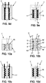
- the reliefs 9 of the inner part 4 are formed by symmetrical rings 30 of revolution, but not necessarily, around the axis A of attachment, projecting on the lateral surface.
- the rings 30 form in themselves projections 31 and form between two successive rings 30 in the longitudinal direction of the recesses 32 .
- the projections 31 and the recesses 32 are therefore symmetrical with respect to the fixing axis A.
- the reliefs 16 of the outer part 11 are formed by rings 33 symmetrical of revolution, but not necessarily, around the axis A of attachment, projecting on the inner surface surface 12 of the outer part 11.
- the rings 33 in themselves form projections 34 on the inner lateral surface 12 of the outer part 11 and form between two adjacent successive rings 33, in the longitudinal direction, recesses 35 .
- the rings 30, 33 are of square or rectangular section and extend perpendicular to the longitudinal direction, that is to say that they extend transversely on the outer surface of the inner part 4 and the inner surface 12 of the outer part 11.
- the layer 18 of elastomer extends between the projections 31, 34 and the recesses 32, 35 of the two parts 4, 11, so that when viewed in longitudinal section in a plane comprising the fixing axis A, the layer 18 of elastomer forms crenellations, on either side of the axis A fixation.
- the elastomer layer 18 comprises a plurality of transverse sections 37 whose thickness is defined in a transverse direction, between the end of a projection 31 of the inner part 4 and the bottom of a hollow. 35 of the outer part 11 and between the end of a projection 34 of the outer part 11 and the bottom of a hollow 32 of the inner part 4.
- the elastomer layer 18 also comprises a plurality of longitudinal sections 38 , whose thickness is defined in the longitudinal direction, interconnecting the cross sections 37 in pairs.
- each projection 31, 34 is covered with two longitudinal sections 38 and a transverse section.
- the transverse sections 37 When viewed in a longitudinal plane P comprising the attachment axis A, the transverse sections 37 thus form, on one side of the attachment axis A, transverse portions 37a, offset each other in the transverse direction, and on the other side of the fastening axis A, transverse portions 37b also offset from one another in a crenel in the transverse direction.
- the longitudinal sections 38 form longitudinal portions 38a, 38b, spaced apart from each other longitudinally in a predetermined pitch, on each projection 31, 34, two longitudinal portions 38a, 38b and a portion 37a, 37b cross are adhered.
- the behavior of the elastomer layer 18 is substantially similar to that described in the first embodiment with square or rectangular nets.
- the transverse sections 37 work in shear and the longitudinal sections 38 work in tension and in compression. More specifically, when seen in section in a longitudinal plane P comprising the axis A, when a longitudinal portion 38a of a first longitudinal section 38 works in compression, then the longitudinal portion 38b in the longitudinal direction works in compression, and and so on.
- the transverse sections 37 work in tension and in compression
- the longitudinal sections 38 work in shear. More precisely, when viewed in section in a longitudinal plane P comprising the axis A, when a portion 37a of a transverse section 37, on a first side of the attachment axis A, is working in compression, then the portion 37b of this same cross section 37 on the other side of the fastening axis A works in tension, and vice versa.
- the layer 18 of elastomer still works at the same time in tension, in compression and in tension.
- the shape of the rings 30, 33 is not necessarily square or rectangular, but may be triangular, trapezoidal or rounded.
- the stiffness and the damping coefficient of the device can thus be adjusted simply by adapting the number of rings 30, 33 and their distance between them, in order to obtain longitudinal portions 37a, 37b and 38a, 38b having the dimensional characteristics. determined.
- the device 1 for fixing and damping thus formed has a great adaptability, and this for a given size.
- the size of the fixing device 1 is given by the outer dimensions of the outer part 11. However, it is not necessary to modify these dimensions to modify the characteristics of the device 1.
- the reliefs 9, 16, that is to say the threads 21, 24 or the rings 30, 33 it is possible to obtain different performances for the device 1 according to the desired applications.
- Such an arrangement makes it possible in particular to minimize the non-linear behavior of the damping.
- It is also possible to promote the damping of the vibrations in the longitudinal direction or the transverse directions by adjusting the size of the portions of the corresponding elastomer layer 18. By playing on the pitch between the portions 28a and 28b, 29a and 29b, 38a and 38b, the stiffness can again be adapted.
- the longitudinal dimension of the inner part 4 may be substantially equal to that of the outer part 11, so that the whole of the outer lateral surface 12 of the outer part 11 is opposite the surface The outer side of the inner part as shown on figures 1 , 4a and 6b .
- the longitudinal dimension of the inner part 4 can be quite lower than that of the outer part 11.
- the stiffness of the device 1 is substantially proportional to the surface total adhered layer 18 of elastomer.
- the modifications made to the reliefs 9, 16 make it possible to modify easily without reviewing the dimensions.
- external device 1 the characteristics of the layer 18 of elastomer for a given device 1 dimensions.
- the device 1 is mounted between the panel 2 and the equipment 3 in the following manner.
- the device 1, comprising the inner part 4, the outer part 11 and the elastomer layer 18 rigidly connecting the two parts 4, 11, is placed in an opening on the panel 2 provided for this purpose.
- the outer lateral surface of the outer member 11 is then rigidly fixed to the panel 2 in the opening provided.
- the diameter of the opening in the panel is greater than the outside diameter of the inner part 11.
- the space between the outer side surface and the surface of the opening in the panel 2 is filled with a glue-like substance 39 , providing the rigid attachment.
- the device 1 is then embedded in the panel 2.
- the equipment 3 is then rigidly attached to the internal part 4.
- the equipment 3 comprises a tab 40 which bears on the upper surface 6 of the inner part 4.
- the tab 40 comprises a bore, which is placed coaxially with the bore 8 in the inner part 4.
- a screw-type fastening means 41 is then inserted into the piercing of the lug 40 and the piercing 8 of the internal part 4, to cooperate with the tapping of the piercing 8 of the internal part 4.
- the equipment 3 is then rigidly fixed on the internal part 4.
- the device 1 thus makes it possible to ensure the rigid attachment between the panel 2 and the equipment 3 while offering a damping of the vibrations of the panel 2 to the equipment 3, or the opposite, by the layer 18 of elastomer.
- a plurality of devices 1 is used to ensure the attachment between the panel 2 and the equipment 3.
- the devices 1 are distributed at the periphery of the equipment 3, and are arranged parallel to each other, that is to say that their attachment axes A are parallel, as shown in FIG. figure 7 .
- the devices 1 may be arranged to form an angle between them, that is to say that their axes A fixing are not parallel.
- two devices 1 are arranged at 90 °, to allow to rigidly assemble two panel-type elements 2 by means of an intermediate plate 42 .
- the device 1 can be used to assemble interface rings between a launcher and a satellite.
- the first element 2 is a launcher interface ring, mounted on a satellite body
- the second element 3 is a satellite interface ring, mounted on a launcher.
- the inner part 4 and the outer part 11 are preferably made of metal.
- One of the difficulties in the method of manufacturing the device 1 is to ensure that the relative position of the inner part 4 relative to the outer part 11 is maintained so that the space between them respects the desired dimensioning of the layer 18 elastomer.
- the inner part 4 and the outer part 11 are first machined each from a blank.
- a first blank 4 ' intended to form the inner part 4
- has an outer lateral surface 5' which is machined so as to have reliefs 9 '
- a second blank 11 ' intended to form the outer piece 11
- has an inner lateral surface 12' which is machined so as to have reliefs 16 'complementary to those 9' of the first blank 4 '.
- This first embodiment of the manufacturing method is particularly suitable for the device 1 described with reference to the first embodiment, in which the reliefs 9, 16 are formed by threads 21, 24.
- the 5 'lateral surface of the first blank is threaded to form a thread 21 'and the inner side surface 12' of the second blank 11 'is threaded to form a complementary thread 24'.
- first blank 4 ' comprises at one end a conical head 43
- second blank 11' comprises at one end a conical seat shoulder 44 , complementary to the head 43.
- the first blank 4 ' can then be screwed into the second blank 11' thanks to their complementary threads 21 ', 24', until the head 43 are housed in the seat 44 with minimal or no play, ensuring the relative position between the two blanks 4 ', 11', in which a space 45 is formed between them.
- An elastomer can then be injected into the space 45.
- the head 43 of the first blank 4 ' comprises channel openings 46 for the pressure injection of the elastomer, to form the elastomer layer 18.
- the elastomer then fills the space 45.
- a step of adhesion of the elastomer to the inner wall 5 'of the first blank 4' and the inner side wall 12 'of the second blank 11' is provided. Adhesion is obtained for example by heating the assembly. The elastomer is thus fixed rigidly to the blanks 4 ', 11'.
- the thread 21 'of the first blank is covered with an elastomeric tube, which adheres to the outer side wall 5'. Then, the first blank 4 'thus covered is screwed with force into the second blank 11'. An additional bonding step allows the elastomeric tube to adhere to the inner side wall 12 'of the first blank.
- the blank 1 'of device 1 is machined so as to obtain the desired final dimensions of the device 1 for the upper surfaces 6, 13, the lower surfaces 7, 14 and the outer lateral surface of the outer part 11.
- the head 43 and the seat 44 are cut.
- a first blank 4 'of the inner part 4 is manufactured simultaneously with a second blank 5' of the inner part 5, in the same step, during which the relative position between the two blanks respects the final relative position between the internal part 4 and the external part 5 desired.
- the blank 1 'of the device comprising the first blank 4' and the second blank 11 'is manufactured by three-dimensional printing, and more particularly by the technique known as "ALM"("Additive Layer Manufacturing”).
- ALM additive Layer Manufacturing
- the first blank 4 'and the second blank 11' are then obtained simultaneously.
- the first blank 4 ' has on the outer surface 5' reliefs 9 'complementary reliefs 16' on the inner surface 12 'of the second blank 11'.
- Bars 47 of material are formed on the blank 1' complete at both ends between the two blanks 4 ', 11' to maintain their relative positioning, a space 45 being formed between them.
- the two blanks 4 ', 11' forming the complete blank 1 'and the bridges 47 may be obtained by casting.
- the elastomer is injected between the bridges 47 in the space 45 between the two blanks 4 ', 11' so as to cover their reliefs 9 ', 16' and adhere to the outer surface 5 'of the first blank 4' and the inner surface 12 'of the second blank 11'.
- the blank 1 'of device 1 has dimensions greater than those of the final device 1, so that, as previously, the blank 1' is machined to obtain the desired final dimensions of the device 1, the bridges 47 being then eliminated.
- first blank 4 'and the second blank 11' are not to the final dimensions of the inner part 4 and the outer part 11 makes it possible to inject the elastomer under pressure into the space 45 between the blanks 4 ' , 11 'avoiding the risk of material rupture.
- the thickness of the outer part 11, that is to say the dimension between its inner surface 12 and its outer surface may have to be small to respect the dimensioning of the elastomer layer 18 and the reliefs 9 , 16, while respecting a maximum size.
- the device 1 can then be assembled between the two elements 2, 3 of the satellite as described above.
- the device 1 is therefore a single piece to handle for the assembly of the two elements 2, 3, making the assembly easier.
- the number of pieces to be stored is also reduced, making management easier and therefore less expensive.
- the device 1 thus formed also allows great adaptability while maintaining a given size by sizing on the one hand the space 45 between the blanks 4 ', 11' and on the other hand the reliefs 9, 16 according to the desired performance.
Landscapes
- Engineering & Computer Science (AREA)
- General Engineering & Computer Science (AREA)
- Mechanical Engineering (AREA)
- Vibration Prevention Devices (AREA)
- Connection Of Plates (AREA)
- Standing Axle, Rod, Or Tube Structures Coupled By Welding, Adhesion, Or Deposition (AREA)
- Fluid-Damping Devices (AREA)
Claims (20)
- Befestigungsvorrichtung (1) zur Dämpfung zwischen zwei zusammenzusetzenden Elementen (2, 3), wobei die Befestigungsvorrichtung Folgendes umfasst:ein rohrförmiges Innenteil (4), das sich entlang einer Befestigungsachse (A) erstreckt, starr auf einem zusammenzusetzenden Element (3) zu befestigen ist und eine Seitenaußenfläche (5) umfasst;ein rohrförmiges, hohles Außenteil (11), das sich entlang der Befestigungsachse (A) erstreckt, starr auf einem anderen zusammenzusetzenden Element (2) zu befestigen ist und eine Seiteninnenfläche (12) aufweist, wobei das Innenteil (4) derart im Außenteil (3) angeordnet ist, dass die Außenfläche des Innenteils der Innenfläche des Außenteils zugewandt ist;eine Elastomerschicht (18) zwischen dem Außenteil (11) und dem Innenteil (4),wobei die Befestigungsvorrichtung dadurch gekennzeichnet ist, dass die Seitenaußenfläche (5) des Innenteils (4) mindestens einen unregelmäßigen Abschnitt umfasst und die Seiteninnenfläche (12) des Außenteils (11) mindestens einen unregelmäßigen Abschnitt umfasst, der komplementär zum unregelmäßigen Abschnitt der Außenfläche (5) des Innenteils (4) ist, wobei die Elastomerschicht (18) eine erste Seite (19), die auf dem unregelmäßigen Abschnitt der Seitenaußenfläche (5) des Innenteils (4) anhaftet, und eine zweite Seite (20), die zur ersten Seite (19) entgegengesetzt ist und auf dem unregelmäßigen Abschnitt der Seiteninnenfläche (12) des Außenteils (11) anhaftet, aufweist, und dadurch gekennzeichnet, dass die Elastomerschicht (18) in einer Längsebene (P), die die Befestigungsachse (A) umfasst, im Querschnitt betrachtet Folgendes umfasst:auf jeder Seite der Befestigungsachse (A) mindestens drei Längsabschnitte (28a, 28b, 38a, 38b, 29a, 29b), die entlang der Befestigungsachse (A) in einem vordefinierten Abstand zueinander angeordnet sind, wobei mindestens einer der drei Längsabschnitte (28a, 28b, 38a, 38b, 29a, 29b) entlang der Längsachse (A) gegensätzlich zu den beiden anderen Abschnitten wirkt, undmindestens zwei Querabschnitte (27a, 27b, 37a, 37b, 29a, 29b), die in eine Richtung quer zur Befestigungsachse (A) wirken, wobei ein erster Abschnitt (27a, 29a, 37a) auf einer ersten Seite der Befestigungsachse (A) angeordnet ist und der zweite Abschnitt (27b, 29b, 37b) auf der anderen Seite der Befestigungsachse (A) angeordnet ist.
- Vorrichtung (1) nach Anspruch 1, wobei der unregelmäßige Abschnitt der Außenfläche (5) des Innenteils (4) und der unregelmäßige Abschnitt der Innenfläche (12) des Außenteils (11) Ringe (30, 33) um die Längsrichtung herum umfassen.
- Vorrichtung (1) nach Anspruch 2, wobei die Ringe (30, 33) im Wesentlichen senkrecht zur Längsrichtung sind und eine rechteckige Form aufweisen.
- Vorrichtung (1) nach einem der vorhergehenden Ansprüche, wobei der unregelmäßige Abschnitt der Außenfläche (5) des Innenteils (4) mindestens ein Gewinde (21) um die Längsrichtung herum umfasst und wobei der unregelmäßige Abschnitt der Innenfläche (12) des Außenteils (11) mindestens ein Gewinde (24) umfasst, das zum Gewinde (21) des Innenteils (4) komplementär ist, und wobei die Elastomerschicht (8) die Gewinde (21, 24) mindestens teilweise bedeckt.
- Vorrichtung (1) nach Anspruch 4, wobei die Gewinde (21, 24) rechteckig sind.
- Vorrichtung (1) nach Anspruch 4, wobei die Gewinde (21, 24) dreieckig sind.
- Vorrichtung (1) nach einem der vorhergehenden Ansprüche, wobei das Innenteil (4) und das Außenteil (11) Metallteile sind.
- Vorrichtung (1) nach einem der vorhergehenden Ansprüche, wobei, wenn sich die Vorrichtung im Ruhezustand befindet, die Dicke der Elastomerschicht (18) zwischen deren beiden Seiten (19, 20) konstant ist.
- Vorrichtung (1) nach einem der vorhergehenden Ansprüche, wobei die Elastomerschicht (18) in der Längsrichtung und rund um die Längsrichtung durchgehend ist, so dass die Elastomerschicht (18) die Form eines einstückig ausgebildeten Elastomerteils aufweist.
- Vorrichtung (1) nach einem der vorhergehenden Ansprüche, wobei das Innenteil (4) eine Bohrung (8) aufweist.
- Verfahren zur Herstellung eines dämpfenden Befestigungselements nach einem der vorhergehenden Ansprüche, folgende Schritte umfassend:Herstellung eines Rohlings (1') einer Vorrichtung, umfassend einen Rohling (4') eines Innenteils (4), auf dem eine Außenfläche (5') ausgebildet ist, und einen Rohling (11') eines Außenteils (11), auf dem eine Innenfläche (12') ausgebildet ist, wobei die Innenfläche (11') des Rohlings (11') des Außenteils (11) der Außenfläche (5') des Rohlings (4') des Innenteils (4) zugewandt ist;Einbringen eines Elastomers zwischen die Außenfläche (5') des Rohlings (4') des Innenteils (4) und die Innenfläche (12') des Rohlings (11') des Außenteils (11);Anhaften des Elastomers auf der Außenfläche (5') des Rohlings (4') des Innenteils (4) und auf der Innenfläche (12') des Rohlings (11') des Außenteils (11).
- Herstellungsverfahren nach Anspruch 11, wobei der Schritt des Einbringens des Elastomers ein Einspritzschritt ist.
- Herstellungsverfahren nach Anspruch 11 oder 12, wobei die Herstellung des Rohlings (1') der Vorrichtung (1) folgende Arbeitsvorgänge umfasst:Bearbeitung des Rohlings (4') des Innenteils (4), wobei die Außenfläche (5') ein Gewinde ausbildet,Bearbeitung des Rohlings (11') des Außenteils (11), wobei die Innenfläche (12') ein Außengewinde ausbildet, das zum Gewinde komplementär ist,Verschrauben des Rohlings (4') des Innenteils (4) im Rohling (11') des Außenteils (11), um den Rohling (1') der Vorrichtung (1) zu erhalten.
- Herstellungsverfahren nach Anspruch 13, wobei die Herstellung des Rohlings (1') der Vorrichtung (1) die folgenden Arbeitsschritte umfasst:gleichzeitiges dreidimensionales Drucken des Rohlings (11') des Außenteils (11) und des Rohlings (4') des Innenteils (4) in seiner Position im Rohling (11') des Außenteils (11),Herstellen von mindestens einem Steg (47) zwischen dem Rohling (11') des Außenteils (11) und dem Rohling (4') des Innenteils (4), um die Beibehaltung ihrer jeweiligen Position zu gewährleisten.
- Herstellungsverfahren nach einem der Ansprüche 11 bis 14, umfassend einen abschließenden Schritt zur Bearbeitung des Rohlings (1') mit den gewünschten endgültigen Abmessungen der Vorrichtung (1).
- Anordnung, mindestens zwei Elemente umfassend, die unter Verwendung von mindestens einer Vorrichtung (1) nach einem der Ansprüche 1 bis 10 zusammengesetzt sind, wobei
das Außenteil (11) starr auf einem ersten Element (2) befestigt ist und das Innenteil (4) starr auf dem zweiten Element (3) befestigt ist. - Anordnung nach Anspruch 16, wobei das Innenteil (4) eine Bohrung (8) umfasst, wobei das zweite Element (3) über eine durch die Bohrung (8) hindurchtretende Schraube starr auf dem Innenelement (4) befestigt ist.
- Anordnung nach Anspruch 16 oder 17, wobei das erste Element (2) eine tragende Struktur, etwa ein Satellitenkörper, und das zweite Element (3) eine Einrichtung des Satelliten ist.
- Anordnung nach Anspruch 17 oder 18, wobei das erste Element (2) ein Werfer-Grenzflächenring ist und das zweite Element (3) ein Satelliten-Grenzflächenring ist.
- Verfahren zur Zusammensetzung einer Trageanordnung nach einem der Ansprüche 16 bis 19, umfassend einen Schritt des starren Befestigens des Außenteils (11) der Befestigungsvorrichtung (1) auf dem ersten Element (2) und einen Schritt des starren Befestigens des zweiten Elements (3) auf dem Innenteil (4) der Befestigungsvorrichtung (1).
Applications Claiming Priority (2)
| Application Number | Priority Date | Filing Date | Title |
|---|---|---|---|
| FR1463334A FR3031146B1 (fr) | 2014-12-24 | 2014-12-24 | Dispositif de fixation amortissant entre deux elements a assembler, procede de fabrication d'un tel dispositif, ensemble de deux elements assembles a l'aide d'un tel dispositif, et procede d'assemblage |
| PCT/FR2015/053192 WO2016102792A1 (fr) | 2014-12-24 | 2015-11-24 | Dispositif de fixation amortissant entre deux éléments à assembler, procédé de fabrication d'un tel dispositif, ensemble de deux éléments assemblés à l'aide d'un tel dispositif, et procédé d'assemblage |
Publications (2)
| Publication Number | Publication Date |
|---|---|
| EP3237762A1 EP3237762A1 (de) | 2017-11-01 |
| EP3237762B1 true EP3237762B1 (de) | 2019-02-06 |
Family
ID=53008619
Family Applications (1)
| Application Number | Title | Priority Date | Filing Date |
|---|---|---|---|
| EP15817452.4A Active EP3237762B1 (de) | 2014-12-24 | 2015-11-24 | Vorrichtung zur stossdämpfenden befestigung zweier zu montierender elemente, verfahren zur herstellung solch einer vorrichtung, satz aus zwei anhand solch einer vorrichtung montierten elementen und montageverfahren |
Country Status (7)
| Country | Link |
|---|---|
| US (1) | US10400804B2 (de) |
| EP (1) | EP3237762B1 (de) |
| JP (1) | JP6286109B1 (de) |
| CN (1) | CN107002727B (de) |
| ES (1) | ES2722024T3 (de) |
| FR (1) | FR3031146B1 (de) |
| WO (1) | WO2016102792A1 (de) |
Families Citing this family (13)
| Publication number | Priority date | Publication date | Assignee | Title |
|---|---|---|---|---|
| EP3372390B1 (de) * | 2017-03-09 | 2021-11-10 | AIRBUS HELICOPTERS DEUTSCHLAND GmbH | Verfahren zur reparatur einer sandwichkomponente mit einem zwischen einer ersten und einer zweiten abdeckplatte angeordneten kernelement |
| US11084230B1 (en) | 2018-03-29 | 2021-08-10 | Kineticure, Llc | Bonded nutplate rapid cure system |
| EP3564542A1 (de) * | 2018-05-03 | 2019-11-06 | A. Raymond et Cie | Abstandshalter für versandbolzen und verfahren zur verwendung davon |
| CN109555960B (zh) * | 2018-11-30 | 2020-11-24 | 长光卫星技术有限公司 | 变刚度柔性阻尼支腿 |
| DE102020103436A1 (de) | 2020-02-11 | 2021-08-12 | Airbus Operations Gmbh | Verfahren und Vorrichtung zur Befestigung einer Kabinenkomponente an einer Primärstruktur |
| EP3892885A1 (de) * | 2020-04-09 | 2021-10-13 | Nederlandse Organisatie voor toegepast- natuurwetenschappelijk Onderzoek TNO | Vorrichtung zur befestigung einer last an einem träger, anordnung, fahrzeug und verfahren |
| CA3178013A1 (en) | 2020-05-12 | 2021-11-18 | Raymond Disantis | Blind fastener |
| US20230348112A1 (en) * | 2020-07-08 | 2023-11-02 | Airbus Defence And Space Sas | Damped machined primary structure for a spacecraft, satellite incorporating this primary structure and method for manufacturing such a satellite |
| WO2022020250A1 (en) | 2020-07-20 | 2022-01-27 | Sky Climber Fasteners LLC | Rivetless nut plate |
| FR3115083B1 (fr) * | 2020-10-12 | 2023-10-20 | Arianegroup Sas | Dispositif d’amortissement bi-matériaux pour engin spatial et procédé de fabrication du dispositif d’amortissement |
| TWI737525B (zh) * | 2020-10-28 | 2021-08-21 | 緯創資通股份有限公司 | 螺母構件與包含其之電子裝置 |
| EP4119264A1 (de) * | 2021-07-16 | 2023-01-18 | Heraeus Amloy Technologies GmbH | Gewindeelement umfassend oder bestehend aus einem metall mit einem innengewinde |
| FR3141225A1 (fr) * | 2022-10-25 | 2024-04-26 | Safran Electronics & Defense | Element de liaison pour equipement de vision infrarouge |
Family Cites Families (18)
| Publication number | Priority date | Publication date | Assignee | Title |
|---|---|---|---|---|
| US2074340A (en) * | 1933-04-17 | 1937-03-23 | Transit Res Corp | Vehicle springing system |
| US3975007A (en) * | 1974-05-20 | 1976-08-17 | Ace Controls, Inc. | Resilient mounting structure |
| US4922573A (en) * | 1989-04-14 | 1990-05-08 | Grumman Aerospace Corporation | Compression fitted bushing installation |
| US4973208A (en) * | 1989-08-31 | 1990-11-27 | Gauron Richard F | Inset panel fastener with floating member |
| DE4413743A1 (de) * | 1994-04-20 | 1995-10-26 | Hilti Ag | Befestigungsanker |
| US5551661A (en) * | 1994-10-11 | 1996-09-03 | Bunker; Donald D. | Automotive transmission mount |
| JPH0972379A (ja) * | 1995-09-07 | 1997-03-18 | Nec Eng Ltd | 防振締結機構 |
| DE19625176A1 (de) * | 1996-06-24 | 1998-01-08 | Upat Max Langensiepen Kg | Befestigungselement für nichtruhende Belastungen |
| US5876023A (en) * | 1996-09-18 | 1999-03-02 | Lord Corporation | Vibration isolation insert for aircraft floor planels and the like |
| JP2000145889A (ja) * | 1998-11-09 | 2000-05-26 | Nec Eng Ltd | 搭載機器の締結構造 |
| US6601818B1 (en) * | 2000-10-12 | 2003-08-05 | Lord Corporation | Tilting mount with integral flange |
| DE20105013U1 (de) * | 2001-03-22 | 2002-08-01 | Fischer Artur Werke Gmbh | Ankerhülse zur Injektionsbefestigung |
| JP2003104229A (ja) * | 2001-09-28 | 2003-04-09 | Mazda Motor Corp | サスペンションクロスメンバー取付用ブッシュ、及びサスペンションクロスメンバーの取付構造 |
| DE102004019917A1 (de) * | 2004-04-21 | 2005-11-17 | Zf Friedrichshafen Ag | Lager für ein Kraftfahrzeug |
| US7249756B1 (en) | 2006-02-01 | 2007-07-31 | Csa Engineering, Inc. | Low-profile, multi-axis, highly passively damped, vibration isolation mount |
| JP5210018B2 (ja) * | 2008-03-28 | 2013-06-12 | 本田技研工業株式会社 | マウントブッシュ |
| ES2571941T3 (es) * | 2009-12-09 | 2016-05-27 | Vossloh Werke Gmbh | Taco roscado para fijaciones de carril |
| JP4865907B1 (ja) * | 2010-12-29 | 2012-02-01 | ジェイ・バス株式会社 | 組合せハニカムピース構造によるハニカムパネル |
-
2014
- 2014-12-24 FR FR1463334A patent/FR3031146B1/fr not_active Expired - Fee Related
-
2015
- 2015-11-24 EP EP15817452.4A patent/EP3237762B1/de active Active
- 2015-11-24 WO PCT/FR2015/053192 patent/WO2016102792A1/fr active Application Filing
- 2015-11-24 ES ES15817452T patent/ES2722024T3/es active Active
- 2015-11-24 JP JP2017533849A patent/JP6286109B1/ja active Active
- 2015-11-24 CN CN201580066321.4A patent/CN107002727B/zh active Active
- 2015-11-24 US US15/537,232 patent/US10400804B2/en active Active
Non-Patent Citations (1)
| Title |
|---|
| None * |
Also Published As
| Publication number | Publication date |
|---|---|
| ES2722024T3 (es) | 2019-08-07 |
| FR3031146A1 (fr) | 2016-07-01 |
| US10400804B2 (en) | 2019-09-03 |
| US20180266461A1 (en) | 2018-09-20 |
| JP6286109B1 (ja) | 2018-02-28 |
| WO2016102792A1 (fr) | 2016-06-30 |
| CN107002727B (zh) | 2018-12-28 |
| JP2018508715A (ja) | 2018-03-29 |
| CN107002727A (zh) | 2017-08-01 |
| FR3031146B1 (fr) | 2017-01-13 |
| EP3237762A1 (de) | 2017-11-01 |
Similar Documents
| Publication | Publication Date | Title |
|---|---|---|
| EP3237762B1 (de) | Vorrichtung zur stossdämpfenden befestigung zweier zu montierender elemente, verfahren zur herstellung solch einer vorrichtung, satz aus zwei anhand solch einer vorrichtung montierten elementen und montageverfahren | |
| EP3259190B1 (de) | Weltraumfahrzeug mit pfosten zur bildung eines stapels, stapel mit mindestens zwei solchen fahrzeugen in einer trägerrakete und verfahren zur freigabe der fahrzeuge | |
| WO2017055770A1 (fr) | Satellite à corps principal cylindrique, empilement comprenant un tel satellite et ensemble de lancement pour un tel satellite | |
| EP1355120B1 (de) | Vorrichtung zur provisorischen Verbindung und zum pyrotechnischen Trennen von zwei Elementen, ohne Bruch | |
| EP3617075B1 (de) | Vorrichtung zur lokalisierten verbindung mit gesteuerter trennung, die eine multidirektionale verbindungsschicht umfasst | |
| EP2527781B1 (de) | Verbindungselement für einen Körper aus Verbundmaterial eines militärischen Perforationsprojektils | |
| FR3078952A1 (fr) | Systeme de mise en orbite de travail pour un satellite | |
| EP3589550B1 (de) | Verfahren und vorrichtung zum verbinden und linearen trennen zweier zusammengehaltener elemente | |
| EP3982002A1 (de) | Dämpfungsvorrichtung aus zwei materialien für raumfahrzeuge und verfahren zur herstellung dieser dämpfungsvorrichtung | |
| FR2971233A1 (fr) | Substrat amortissant pour panneau structurel de satellite | |
| EP0454546B1 (de) | Vorrichtung zur zeitlichen Halterung eines Objektes an einem Träger mit einer auf Zugkräfte kalibrierten Sollbruchstelle | |
| WO2021122660A1 (fr) | Couche intermédiaire de déformation à raideur macroscopique ajustable pour assemblage collé | |
| EP4045413B1 (de) | Gedämpfte, bearbeitete primärstruktur für ein raumfahrzeug, satellit mit dieser primärstruktur und verfahren zur herstellung eines solchen satelliten | |
| EP3985277B1 (de) | Dämpfungsvorrichtung für raumfahrzeuge und verfahren zur herstellung dieser dämpfungsvorrichtung | |
| FR2829662A1 (fr) | Suspension pour module electronique devant fonctionner durant et apres impacts severes | |
| EP0988446B1 (de) | Verankerungsvorrichtung für eine betätigungseinrichtung einer schwenkbaren schubdüse | |
| EP2715100B1 (de) | System zur reduzierung der dynamik des mobilen abschnitts einer entfaltbaren raketenmotordüse | |
| FR2817955A1 (fr) | Dispositif d'amorcage pour charge explosive et charge formee incorporant un tel dispositif d'amorcage | |
| EP3023733A1 (de) | Pyrotechnische trennvorrichtung, die ein stossdämpferorgan umfasst | |
| WO2004088150A2 (fr) | Assemblage pour lanceur comprenant un dispositif de fixation susceptible d'isoler un equipement d'un environnement dynamique et/ou pyrotechnique | |
| FR3021079A1 (fr) | Decoupleur pour dispositif de montage antivibratoire et dispositif de montage antivibratoire comprenant un tel decoupleur |
Legal Events
| Date | Code | Title | Description |
|---|---|---|---|
| STAA | Information on the status of an ep patent application or granted ep patent |
Free format text: STATUS: THE INTERNATIONAL PUBLICATION HAS BEEN MADE |
|
| PUAI | Public reference made under article 153(3) epc to a published international application that has entered the european phase |
Free format text: ORIGINAL CODE: 0009012 |
|
| STAA | Information on the status of an ep patent application or granted ep patent |
Free format text: STATUS: REQUEST FOR EXAMINATION WAS MADE |
|
| 17P | Request for examination filed |
Effective date: 20170524 |
|
| AK | Designated contracting states |
Kind code of ref document: A1 Designated state(s): AL AT BE BG CH CY CZ DE DK EE ES FI FR GB GR HR HU IE IS IT LI LT LU LV MC MK MT NL NO PL PT RO RS SE SI SK SM TR |
|
| AX | Request for extension of the european patent |
Extension state: BA ME |
|
| DAV | Request for validation of the european patent (deleted) | ||
| DAX | Request for extension of the european patent (deleted) | ||
| GRAP | Despatch of communication of intention to grant a patent |
Free format text: ORIGINAL CODE: EPIDOSNIGR1 |
|
| STAA | Information on the status of an ep patent application or granted ep patent |
Free format text: STATUS: GRANT OF PATENT IS INTENDED |
|
| INTG | Intention to grant announced |
Effective date: 20180911 |
|
| GRAS | Grant fee paid |
Free format text: ORIGINAL CODE: EPIDOSNIGR3 |
|
| GRAA | (expected) grant |
Free format text: ORIGINAL CODE: 0009210 |
|
| STAA | Information on the status of an ep patent application or granted ep patent |
Free format text: STATUS: THE PATENT HAS BEEN GRANTED |
|
| RAP1 | Party data changed (applicant data changed or rights of an application transferred) |
Owner name: AIRBUS DEFENCE AND SPACE SAS |
|
| AK | Designated contracting states |
Kind code of ref document: B1 Designated state(s): AL AT BE BG CH CY CZ DE DK EE ES FI FR GB GR HR HU IE IS IT LI LT LU LV MC MK MT NL NO PL PT RO RS SE SI SK SM TR |
|
| REG | Reference to a national code |
Ref country code: GB Ref legal event code: FG4D Free format text: NOT ENGLISH |
|
| REG | Reference to a national code |
Ref country code: CH Ref legal event code: EP Ref country code: AT Ref legal event code: REF Ref document number: 1095095 Country of ref document: AT Kind code of ref document: T Effective date: 20190215 |
|
| REG | Reference to a national code |
Ref country code: DE Ref legal event code: R096 Ref document number: 602015024441 Country of ref document: DE |
|
| REG | Reference to a national code |
Ref country code: IE Ref legal event code: FG4D Free format text: LANGUAGE OF EP DOCUMENT: FRENCH |
|
| REG | Reference to a national code |
Ref country code: CH Ref legal event code: NV Representative=s name: VALIPAT S.A. C/O BOVARD SA NEUCHATEL, CH |
|
| REG | Reference to a national code |
Ref country code: NL Ref legal event code: FP |
|
| REG | Reference to a national code |
Ref country code: LT Ref legal event code: MG4D |
|
| PG25 | Lapsed in a contracting state [announced via postgrant information from national office to epo] |
Ref country code: SE Free format text: LAPSE BECAUSE OF FAILURE TO SUBMIT A TRANSLATION OF THE DESCRIPTION OR TO PAY THE FEE WITHIN THE PRESCRIBED TIME-LIMIT Effective date: 20190206 Ref country code: PT Free format text: LAPSE BECAUSE OF FAILURE TO SUBMIT A TRANSLATION OF THE DESCRIPTION OR TO PAY THE FEE WITHIN THE PRESCRIBED TIME-LIMIT Effective date: 20190606 Ref country code: NO Free format text: LAPSE BECAUSE OF FAILURE TO SUBMIT A TRANSLATION OF THE DESCRIPTION OR TO PAY THE FEE WITHIN THE PRESCRIBED TIME-LIMIT Effective date: 20190506 Ref country code: FI Free format text: LAPSE BECAUSE OF FAILURE TO SUBMIT A TRANSLATION OF THE DESCRIPTION OR TO PAY THE FEE WITHIN THE PRESCRIBED TIME-LIMIT Effective date: 20190206 Ref country code: LT Free format text: LAPSE BECAUSE OF FAILURE TO SUBMIT A TRANSLATION OF THE DESCRIPTION OR TO PAY THE FEE WITHIN THE PRESCRIBED TIME-LIMIT Effective date: 20190206 |
|
| REG | Reference to a national code |
Ref country code: ES Ref legal event code: FG2A Ref document number: 2722024 Country of ref document: ES Kind code of ref document: T3 Effective date: 20190807 |
|
| REG | Reference to a national code |
Ref country code: AT Ref legal event code: MK05 Ref document number: 1095095 Country of ref document: AT Kind code of ref document: T Effective date: 20190206 |
|
| PG25 | Lapsed in a contracting state [announced via postgrant information from national office to epo] |
Ref country code: BG Free format text: LAPSE BECAUSE OF FAILURE TO SUBMIT A TRANSLATION OF THE DESCRIPTION OR TO PAY THE FEE WITHIN THE PRESCRIBED TIME-LIMIT Effective date: 20190506 Ref country code: LV Free format text: LAPSE BECAUSE OF FAILURE TO SUBMIT A TRANSLATION OF THE DESCRIPTION OR TO PAY THE FEE WITHIN THE PRESCRIBED TIME-LIMIT Effective date: 20190206 Ref country code: HR Free format text: LAPSE BECAUSE OF FAILURE TO SUBMIT A TRANSLATION OF THE DESCRIPTION OR TO PAY THE FEE WITHIN THE PRESCRIBED TIME-LIMIT Effective date: 20190206 Ref country code: RS Free format text: LAPSE BECAUSE OF FAILURE TO SUBMIT A TRANSLATION OF THE DESCRIPTION OR TO PAY THE FEE WITHIN THE PRESCRIBED TIME-LIMIT Effective date: 20190206 Ref country code: GR Free format text: LAPSE BECAUSE OF FAILURE TO SUBMIT A TRANSLATION OF THE DESCRIPTION OR TO PAY THE FEE WITHIN THE PRESCRIBED TIME-LIMIT Effective date: 20190507 Ref country code: IS Free format text: LAPSE BECAUSE OF FAILURE TO SUBMIT A TRANSLATION OF THE DESCRIPTION OR TO PAY THE FEE WITHIN THE PRESCRIBED TIME-LIMIT Effective date: 20190606 |
|
| PG25 | Lapsed in a contracting state [announced via postgrant information from national office to epo] |
Ref country code: CZ Free format text: LAPSE BECAUSE OF FAILURE TO SUBMIT A TRANSLATION OF THE DESCRIPTION OR TO PAY THE FEE WITHIN THE PRESCRIBED TIME-LIMIT Effective date: 20190206 Ref country code: RO Free format text: LAPSE BECAUSE OF FAILURE TO SUBMIT A TRANSLATION OF THE DESCRIPTION OR TO PAY THE FEE WITHIN THE PRESCRIBED TIME-LIMIT Effective date: 20190206 Ref country code: AL Free format text: LAPSE BECAUSE OF FAILURE TO SUBMIT A TRANSLATION OF THE DESCRIPTION OR TO PAY THE FEE WITHIN THE PRESCRIBED TIME-LIMIT Effective date: 20190206 Ref country code: SK Free format text: LAPSE BECAUSE OF FAILURE TO SUBMIT A TRANSLATION OF THE DESCRIPTION OR TO PAY THE FEE WITHIN THE PRESCRIBED TIME-LIMIT Effective date: 20190206 Ref country code: DK Free format text: LAPSE BECAUSE OF FAILURE TO SUBMIT A TRANSLATION OF THE DESCRIPTION OR TO PAY THE FEE WITHIN THE PRESCRIBED TIME-LIMIT Effective date: 20190206 Ref country code: EE Free format text: LAPSE BECAUSE OF FAILURE TO SUBMIT A TRANSLATION OF THE DESCRIPTION OR TO PAY THE FEE WITHIN THE PRESCRIBED TIME-LIMIT Effective date: 20190206 |
|
| REG | Reference to a national code |
Ref country code: DE Ref legal event code: R097 Ref document number: 602015024441 Country of ref document: DE |
|
| PG25 | Lapsed in a contracting state [announced via postgrant information from national office to epo] |
Ref country code: SM Free format text: LAPSE BECAUSE OF FAILURE TO SUBMIT A TRANSLATION OF THE DESCRIPTION OR TO PAY THE FEE WITHIN THE PRESCRIBED TIME-LIMIT Effective date: 20190206 Ref country code: PL Free format text: LAPSE BECAUSE OF FAILURE TO SUBMIT A TRANSLATION OF THE DESCRIPTION OR TO PAY THE FEE WITHIN THE PRESCRIBED TIME-LIMIT Effective date: 20190206 |
|
| PLBE | No opposition filed within time limit |
Free format text: ORIGINAL CODE: 0009261 |
|
| STAA | Information on the status of an ep patent application or granted ep patent |
Free format text: STATUS: NO OPPOSITION FILED WITHIN TIME LIMIT |
|
| PG25 | Lapsed in a contracting state [announced via postgrant information from national office to epo] |
Ref country code: AT Free format text: LAPSE BECAUSE OF FAILURE TO SUBMIT A TRANSLATION OF THE DESCRIPTION OR TO PAY THE FEE WITHIN THE PRESCRIBED TIME-LIMIT Effective date: 20190206 |
|
| 26N | No opposition filed |
Effective date: 20191107 |
|
| PG25 | Lapsed in a contracting state [announced via postgrant information from national office to epo] |
Ref country code: SI Free format text: LAPSE BECAUSE OF FAILURE TO SUBMIT A TRANSLATION OF THE DESCRIPTION OR TO PAY THE FEE WITHIN THE PRESCRIBED TIME-LIMIT Effective date: 20190206 |
|
| PG25 | Lapsed in a contracting state [announced via postgrant information from national office to epo] |
Ref country code: TR Free format text: LAPSE BECAUSE OF FAILURE TO SUBMIT A TRANSLATION OF THE DESCRIPTION OR TO PAY THE FEE WITHIN THE PRESCRIBED TIME-LIMIT Effective date: 20190206 |
|
| PG25 | Lapsed in a contracting state [announced via postgrant information from national office to epo] |
Ref country code: LU Free format text: LAPSE BECAUSE OF NON-PAYMENT OF DUE FEES Effective date: 20191124 Ref country code: MC Free format text: LAPSE BECAUSE OF FAILURE TO SUBMIT A TRANSLATION OF THE DESCRIPTION OR TO PAY THE FEE WITHIN THE PRESCRIBED TIME-LIMIT Effective date: 20190206 |
|
| PG25 | Lapsed in a contracting state [announced via postgrant information from national office to epo] |
Ref country code: IE Free format text: LAPSE BECAUSE OF NON-PAYMENT OF DUE FEES Effective date: 20191124 |
|
| PG25 | Lapsed in a contracting state [announced via postgrant information from national office to epo] |
Ref country code: CY Free format text: LAPSE BECAUSE OF FAILURE TO SUBMIT A TRANSLATION OF THE DESCRIPTION OR TO PAY THE FEE WITHIN THE PRESCRIBED TIME-LIMIT Effective date: 20190206 |
|
| PG25 | Lapsed in a contracting state [announced via postgrant information from national office to epo] |
Ref country code: MT Free format text: LAPSE BECAUSE OF FAILURE TO SUBMIT A TRANSLATION OF THE DESCRIPTION OR TO PAY THE FEE WITHIN THE PRESCRIBED TIME-LIMIT Effective date: 20190206 Ref country code: HU Free format text: LAPSE BECAUSE OF FAILURE TO SUBMIT A TRANSLATION OF THE DESCRIPTION OR TO PAY THE FEE WITHIN THE PRESCRIBED TIME-LIMIT; INVALID AB INITIO Effective date: 20151124 |
|
| PG25 | Lapsed in a contracting state [announced via postgrant information from national office to epo] |
Ref country code: MK Free format text: LAPSE BECAUSE OF FAILURE TO SUBMIT A TRANSLATION OF THE DESCRIPTION OR TO PAY THE FEE WITHIN THE PRESCRIBED TIME-LIMIT Effective date: 20190206 |
|
| PGFP | Annual fee paid to national office [announced via postgrant information from national office to epo] |
Ref country code: NL Payment date: 20231120 Year of fee payment: 9 |
|
| PGFP | Annual fee paid to national office [announced via postgrant information from national office to epo] |
Ref country code: GB Payment date: 20231123 Year of fee payment: 9 |
|
| PGFP | Annual fee paid to national office [announced via postgrant information from national office to epo] |
Ref country code: IT Payment date: 20231124 Year of fee payment: 9 Ref country code: FR Payment date: 20231120 Year of fee payment: 9 Ref country code: DE Payment date: 20231121 Year of fee payment: 9 Ref country code: CH Payment date: 20231201 Year of fee payment: 9 |
|
| PGFP | Annual fee paid to national office [announced via postgrant information from national office to epo] |
Ref country code: BE Payment date: 20231120 Year of fee payment: 9 |
|
| PGFP | Annual fee paid to national office [announced via postgrant information from national office to epo] |
Ref country code: ES Payment date: 20240129 Year of fee payment: 9 |