EP3259190B1 - Weltraumfahrzeug mit pfosten zur bildung eines stapels, stapel mit mindestens zwei solchen fahrzeugen in einer trägerrakete und verfahren zur freigabe der fahrzeuge - Google Patents
Weltraumfahrzeug mit pfosten zur bildung eines stapels, stapel mit mindestens zwei solchen fahrzeugen in einer trägerrakete und verfahren zur freigabe der fahrzeuge Download PDFInfo
- Publication number
- EP3259190B1 EP3259190B1 EP16775300.3A EP16775300A EP3259190B1 EP 3259190 B1 EP3259190 B1 EP 3259190B1 EP 16775300 A EP16775300 A EP 16775300A EP 3259190 B1 EP3259190 B1 EP 3259190B1
- Authority
- EP
- European Patent Office
- Prior art keywords
- spacecraft
- posts
- satellite
- locking device
- satellites
- Prior art date
- Legal status (The legal status is an assumption and is not a legal conclusion. Google has not performed a legal analysis and makes no representation as to the accuracy of the status listed.)
- Active
Links
Images




Classifications
-
- B—PERFORMING OPERATIONS; TRANSPORTING
- B64—AIRCRAFT; AVIATION; COSMONAUTICS
- B64G—COSMONAUTICS; VEHICLES OR EQUIPMENT THEREFOR
- B64G1/00—Cosmonautic vehicles
- B64G1/10—Artificial satellites; Systems of such satellites; Interplanetary vehicles
- B64G1/1085—Swarms and constellations
-
- B—PERFORMING OPERATIONS; TRANSPORTING
- B64—AIRCRAFT; AVIATION; COSMONAUTICS
- B64G—COSMONAUTICS; VEHICLES OR EQUIPMENT THEREFOR
- B64G1/00—Cosmonautic vehicles
- B64G1/22—Parts of, or equipment specially adapted for fitting in or to, cosmonautic vehicles
- B64G1/64—Systems for coupling or separating cosmonautic vehicles or parts thereof, e.g. docking arrangements
- B64G1/641—Interstage or payload connectors
-
- B—PERFORMING OPERATIONS; TRANSPORTING
- B64—AIRCRAFT; AVIATION; COSMONAUTICS
- B64G—COSMONAUTICS; VEHICLES OR EQUIPMENT THEREFOR
- B64G1/00—Cosmonautic vehicles
- B64G1/22—Parts of, or equipment specially adapted for fitting in or to, cosmonautic vehicles
- B64G1/64—Systems for coupling or separating cosmonautic vehicles or parts thereof, e.g. docking arrangements
- B64G1/641—Interstage or payload connectors
- B64G1/643—Interstage or payload connectors for arranging multiple satellites in a single launcher
-
- B—PERFORMING OPERATIONS; TRANSPORTING
- B64—AIRCRAFT; AVIATION; COSMONAUTICS
- B64G—COSMONAUTICS; VEHICLES OR EQUIPMENT THEREFOR
- B64G1/00—Cosmonautic vehicles
- B64G1/22—Parts of, or equipment specially adapted for fitting in or to, cosmonautic vehicles
- B64G1/64—Systems for coupling or separating cosmonautic vehicles or parts thereof, e.g. docking arrangements
- B64G1/645—Separators
- B64G1/6455—Pyrotechnics; Using heat
Definitions
- the invention relates to the field of space vehicles, and more particularly but not exclusively, the field of satellites intended to be placed in orbit around the Earth.
- a satellite is put into orbit by means of a launcher, which brings the vehicle into space to drop it according to the planned orbit.
- a problem when several satellites are placed in the same launcher is the management of efforts at launch. Indeed, the launch phase generates vibrations and shocks, in addition to creating a thrust due to acceleration. Thus, a simple stack of satellites on each other produces especially on the satellites located under one or more satellites (with respect to the gravity and / or the direction of the acceleration) efforts likely to damage the equipment carried by this satellite.
- a dispenser typically comprises on the one hand elements fixed to the launcher and possibly on the other hand elements attached to the satellites, that is to say on the one hand elements intended to remain connected to the launcher after the dropping of the satellites and on the other hand elements intended to accompany the dropped satellites. Satellites are thus supported by the dispenser in the manner of a shelf, and do not support each other.
- the design of the dispensers depends on their use. It may also happen that several satellites of different design must be dropped by the same launcher, complicating the structure of the dispenser in the launcher.
- the dispenser includes elements that are integral parts of the launcher. These elements add weight to the thrower and are, in the end, penalizing the mission. The weight distribution in the launcher must also be monitored, especially during the drop. Indeed, in order to maintain the balance of the launcher once launched, the satellite dropping sequence must comply at all times a distribution of the appropriate weight within the launcher. The dropping operations are complicated.
- Another disadvantage of a dispenser is that the shape and dimensions of the satellites are limited by the space offered by the dispenser.
- each satellite comprises a central structure extending over an entire length of the satellite, on which load support panels are placed.
- the central structure of a first satellite is connected with the central structure of a second satellite by means of an alleged detachable strip. The transmission of the forces between the two satellites then passes through their central structure.
- a disadvantage of this system is that it reduces the space available to mount the equipment on the satellites.
- the antennas of a telecommunication satellite are placed on the Earth face of the satellite body.
- the central structure must be accessible by at least one face of the satellite body to allow contact between two central structures of two satellites without contact with other elements. These faces in question are then unavailable to put satellite equipment, including antennas.
- Another disadvantage is that, incidentally to the disadvantage mentioned above, the satellites can not be arranged in a manner optimizing the space inside the launcher, called the undercap space. Indeed, the presence of the central structure imposes an identical orientation for all the satellites stacked.
- the document US 8,511,617 also proposes to stack satellites having a dedicated interface structure.
- the dedicated structure is in the form of a cylinder outside the body of the satellite, the cylinders then serving as support when the satellites are stacked.
- a disadvantage of this solution is that the cylinder outside the satellite also limits the space available for the equipment carried by the satellite.
- the satellites can not be arranged in any direction because of the outer cylinder which imposes a placement of equipment in the space available between the body of the satellite and the cylinder.
- the undercap space is not optimized either.
- a first object of the invention is to provide a spacecraft to be placed in a launcher with at least one other vehicle without the transmission of efforts to damage the vehicles.
- a second object of the invention is to provide a space vehicle to be placed in a launcher with at least one other vehicle not increasing or little or the total weight of the satellite and the weight of the launcher.
- a third object of the invention is to provide a spacecraft to be placed in a launcher with at least one other vehicle offering flexibility in the orientation of vehicles placed in the launcher to optimize the space under the cap.
- a fourth object of the invention is to provide a space vehicle for being placed in a launcher with at least one other vehicle offering flexibility in the shape and dimensions of each stacked vehicle.
- a fifth object of the invention is to propose a space vehicle that can be placed in a launcher with at least one other vehicle in which the interface structure between the two vehicles can be adapted to the equipment that can be installed on satellites.
- a sixth object of the invention is to provide a space vehicle for being placed in a launcher with at least one other vehicle in which the vehicles can be dropped one by one or by group.
- the invention proposes a space vehicle, such as a satellite, intended to be placed in orbit around a planet, the vehicle being according to claim 1.
- the reinforcing structure may comprise reinforcement elements in the form of a branch whose number corresponds at least to the number of posts, each branch being fixed between two posts.
- the branches can then be confused with walls of the equipment carrier module, the support walls for vehicle equipment.
- the reinforcing structure may alternatively comprise reinforcement elements in the form of a branch whose number corresponds at least to the number of poles, each branch being fixed on the one hand to a pole and on the other hand to the same center of attachment.
- the reinforcing branches are connected in pairs by consolidation elements in shear.
- the posts are three in number and are distributed at the vertices of an equilateral triangle.
- the posts are four in number and are distributed at the vertices of a parallelogram.
- Each releasable locking device may comprise for example a magnetic element or a pyrotechnic element.
- Each post may advantageously be provided with two releasable locking devices for stacking the satellite on another satellite or on an interface structure and for stacking another satellite on the satellite.
- each post extends longitudinally between two ends, each end being provided with a locking device.
- the stack of satellites is then made by the ends of the columns, following the longitudinal direction.
- the stresses supported by the columns are then mainly shear stresses, and the poles can be designed (shapes and dimensions) to support these constraints.
- the invention proposes a stack of vehicles as presented above, comprising at least two vehicles integral with each other, the at least one releasable locking device of each pole of a first vehicle. being in the locked state with a locking device on a post of the second vehicle, the posts of each vehicle extending in the same longitudinal direction, the stack further comprising a device for controlling the state of the locking devices .
- the vehicles of the stack are notably satellites comprising a terrestrial face and an anti-Earth face, the Earth and anti-Earth faces being able to be oriented in the longitudinal direction of the poles or in a direction transverse to the poles.
- the invention proposes a launcher of space vehicles, the launcher comprising a vehicle interface structure and at least a first stack of vehicles as presented above. At least the first vehicle of the stack is a vehicle comprising on each post two releasable locking devices, a first locking device of each post of the first vehicle being in the locked state on a locking device of the second vehicle, the second locking device of each pole of the first vehicle being in the locked state on the vehicle interface structure.
- the invention proposes a method of releasing vehicles by means of a launcher as presented above according to claim 17.
- the method comprises a step of separation between a vehicle to dump and a vehicle intended to remain in the launcher by putting the locking devices between the two vehicles in the unlocked state so as to release a single vehicle.
- the release method comprises a step of separating a group of vehicles to be dumped and a vehicle intended to remain in the launcher by putting the locking devices in the unlocked state between a vehicle of the group to be dumped and the vehicle intended to remain in the launcher, so as to drop the group of vehicles.
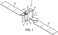
- FIG. 1 to 11 there is shown a first example of a spacecraft, and in particular an example of a telecommunications satellite 1 , intended to orbit the Earth.
- vehicle here designates any element comprising an equipment carrier module capable of transporting equipment. It may be provided with propulsion means of its own, or be intended to be simply dropped at a point in space in the expectation of being subsequently recovered by other space means.
- the equipment carrier module of the satellite 1 is commonly called body 2 of satellite 1, and is of generally parallelepipedal shape, so as to have four faces called face 3 West, face 4 East, face 5 North, face 6 South, with reference to terrestrial cardinal points, and two faces called face 7 Earth and face 8 anti-Earth, with reference to the orientation of these faces with respect to the Earth.
- One or more antennas 9 shown schematically in the figures, are commonly placed on the face 7 Earth to be oriented towards the Earth.
- the satellite 1 is provided with various equipment according to its mission. Typically, the satellite 1 may include 10 solar panels mounted on 5 North and South faces 6 to receive maximum sunlight. On the figure 1 solar panels are shown in solid lines in deployed position. In broken lines, the solar panel 10 mounted on the North face 5 is illustrated in the folded position against this face.
- the satellite 1 can also embark propellers to correct the trajectory of the satellite 1 in orbit. Pointing the satellite in the desired direction generally uses optical sensors, such as star sensors.
- the solar panel 10 mounted on the face 6 South is shown in the folded position against this face 6, and the solar panel 10 and the face 6 South are shown in transparency to reveal the structure of the body 2 of the satellite, here shown schematically . It is then visible that the satellite 1 comprises posts 12 , extending in the same longitudinal direction A , perpendicular to the North 5 and South faces 6 according to the example presented.
- the number of posts 12 is at least three, and is preferably equal to four in the case of the parallelepiped body 2.
- the posts 12 are not aligned, and are arranged for example at the vertices of a triangle in the case of three poles, or to the vertices of a quadrilateral in the case of four poles 12.
- the posts 12 are placed at the periphery of the body 2, that is to say that they are at a distance from a geometric center C of the body 2.
- the posts 12 may be placed at the inner periphery of the body 2, as illustrated in the Figures 1 to 11 , that is to say that the walls bearing the faces 3 to 8 of the body 2 of the satellite 1 envelop and extend between the posts 12. In other words, the posts 12 materialize the real contour of the body 2.
- the posts 12 may be placed at the outer periphery of the body 2, that is to say that the posts define a virtual contour of the body 2, the walls carrying the faces 3 to 8 of the body 2 of the satellite 1 s extending inside this virtual outline.
- the geometric center C of the body 2 is for example the center of gravity of the body 2.
- the four columns 12 are preferably arranged equidistant from the geometric center C, to the vertices of a rectangle or a square, according to the dimensions of faces 5 North and 6 South.
- the walls of the body 2 embodying the faces 3, 4 West, East and 7, 8 Earth, anti-Earth of the satellite 1 are each fixed between two posts 12.
- the volume delimited by the body 2 of the satellite does not therefore extend beyond the posts 12.
- Each post 12 comprises two ends, namely a so-called distal end 13 and a so-called proximal end 14 , the adjectives "distal” and "proximal” being taken here with reference to the distance with a vehicle interface structure of a launcher, as will be explained later, a proximal end 14 being closer to the vehicle interface structure than a distal end 13.
- the distal ends 13 of the posts 12 of the satellite 1 are preferably in the same transverse plane.
- the proximal ends 14 of the posts 12 are also located in the same transverse plane. However, nothing prevents that all the posts 12 of a satellite 1 have a different size to adapt to the configuration of the satellite 1.
- At least one of the ends 13, 14 is provided with a releasable locking device 15 .
- each end 13, 14 of the posts 12 of the satellite 1 is provided with a releasable locking device 15.
- the posts 12 are intended to allow the stacking of at least two satellites 1 one on the other, so that the transmission of forces between the two stacked satellites 1 pass mainly, and preferably exclusively, the posts 12
- the longitudinal dimension of the posts 12 is greater than that of the body 2, and even more advantageously, it is greater than that of the body 2 taking into account equipment such as solar panels 10 when they are folded.
- the distal end 13 and the proximal end 14 are found at least at the same level as the folded solar panels 10, or even extend beyond.
- Two satellites 1 are therefore stacked by placing their respective posts 12 opposite each other and in the same longitudinal direction A, for example by bringing the distal end 13 of the posts 12 of a first satellite 1 of the end 14 proximal posts 12 of a second satellite. Then the locking devices of the first satellite are brought into cooperation with the locking devices of the second satellite, and each locking device is put in the locked state. The two satellites 1 are then integral with each other.
- each satellite stack comprises a device for controlling the satellites 1 locking devices of the stack for separating the satellites to drop them into space.
- the posts 12 are distributed around the periphery of the body 2 so as to ensure a better recovery of the forces between the satellites 1, while taking into account the bulk in the environment of the body 2 of the satellite 1. Indeed, the more posts 12 are away from the center C of geometry of the body 2, and therefore from each other, the stability of the stack of two satellites 1 is greater, and the shear stresses on the stacked columns 12 are high.
- the distance between the posts 12 and the center C geometry sought is therefore the largest possible given the congestion both around the body 2 of the satellites and in the launcher. Therefore, this minimizes the amount of material needed for the posts while maximizing the mechanical strength of the satellite.
- each satellite 1 further comprises a structure 16 of the satellite of the upper or lower satellites to extend partially inside the satellite 1. reinforcement connecting rigidly and transversely each pole 12 of the satellite 1 to at least two other posts 12 of the satellite 1.
- the reinforcing structure 16 comprises reinforcing elements in the form of branches 17 , which connect the posts 12 to each other.
- the number of branches 17 is then equal to the number of poles. 12.
- the branches 17 are four in number and are arranged along the diagonals of the square or rectangle formed by the posts 12. More specifically, each branch 17 is rigidly fixed on the one hand to a post 12 and on the other hand to a same center of attachment of the body 2, which is confused, according to the example presented here, with the geometric center C of the body 2.
- Each branch 17 of the reinforcement structure 16 may have a longitudinal dimension substantially equal to the longitudinal dimension of the post 12 on which it is fixed.
- branches 17 of the reinforcing structure 16 stiffen the posts 12 subjected to efforts tending to deform them transversely, including shear deformations.
- the branches 17 of the reinforcement structure 16, forming a spider inside the body 2 increase the space inside the body 2 of the satellite 1 negligibly.
- the thickness of the branches 17, that is to say, their dimension in the transverse plane can be adapted to be able to arrange the space inside the body 2.
- the space inside the body 1 remains available to place four tanks 18 , the branches 17 defining two by two a compartment.
- the reinforcing structure 16 may be formed by walls of the body 2, in this case according to the example shown, the walls embodying the faces 3, 4 West, East and 7, 8 Earth, anti-Earth satellite 1, which, being fixed on the posts 12 and connecting them two by two, also provide rigidity. In this case, the reinforcing structure 16 does not increase at all the bulk of the body 2 of the satellite 1.
- the reinforcement structure 16 may furthermore comprise shear consolidation elements 19 , to further increase the rigidity of the posts with respect to the shear forces, and connecting the branches 17 in pairs.
- the posts 12, the branches 17 and the shear consolidation elements 19 are sized according to the dimensions and weight of the satellites 1, as well as the forces expected in the launcher.
- the posts 12 may be hollow and used to pass conduits or cables for satellite equipment 1, but may also be full to withstand high stresses.
- the section of the posts 12 may also be of circular, rectangular, T-shaped cross section, etc. depending on the constraints to bear.
- the shape of the cross section may vary along its length.
- Their material can be of any type such as: aluminum, titanium, composite, or another material.
- the Figures 4 to 7 are schematic representations of the posts 12, four in number arranged at the vertices of a square, connected by branches 17 as previously presented, and shear consolidation elements 19 according to two embodiments.
- the consolidation elements 19 are arranged transversely between two branches 17.
- the consolidation elements 19 are in the form of a longitudinal succession of triangular plates, extending into the compartment formed between two adjacent branches 17.
- the consolidation elements 19 are arranged longitudinally between two adjacent branches 17, and are in the form of a rectangular plate.
- the walls of the body 2 embodying the faces 3, 4 West, East and 7, 8 Earth, anti-Earth of the satellite 1 can act as consolidation elements 19 in shear.
- the structure of the satellite thus described makes it possible for the satellites 1 to be stacked in a launcher 20 , so that the transmission of the forces between the satellites 1 passes mainly, or even exclusively, by the posts 12.
- the stacked satellites 1 are placed in the launcher which comprises conventionally a vehicle interface structure 21 .
- the vehicle interface structure 21 is a prior art structure known in itself by those skilled in the art for interfacing a satellite with a launcher, and to secure them.
- the vehicle interface structure 21 can be broken down into two parts: a lower cone 21a secured directly to the launcher and corresponding to the conventional launcher interfaces, and an adapter 21b located between the lower cone 21a. and the stack of the satellites 1.
- the adapter 21b makes it possible to transform the distribution of the forces provided by the stack of the satellites 1 into a distribution of the forces compatible with the specification of the chosen launcher and its standard lower cone 21a.
- the adapter 21b is considered as being able to be supplied with the stack of the satellites 1.
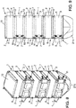
- the Figures 8 and 9 illustrate an example of a stack of six satellites 1 on the vehicle interface structure 21 using a lower cone 21a and an adapter 21b.
- the posts 12 of the satellites are all oriented in the same longitudinal direction A to from the interface structure 21, so that the distal end 13 of the posts 12 of a first satellite 1 is vis-à-vis the proximal end 14 of the posts 12 of a second satellite, the distal end 13 of the posts 12 of the second satellite 1 being opposite the proximal end of the posts 12 of a third satellite and so on to the sixth and last satellite 1.
- the North face 5 of a satellite 1 faces the south face 6 of the adjacent satellite 1 in the stack according to the example presented here.
- the longitudinal dimension of the posts 12 is such that the solar panels of two adjacent satellites 1 are not in contact.
- two adjacent satellites 1 of a stack are in contact only with their posts 12.
- the releasable locking devices are all preferably identical, facilitating the manufacture and management of the satellites 1.
- the posts 12 make it possible to stack the satellites in such a way as to optimize the undercap space in a launcher, in particular by making it possible to stack the satellites by alternating the orientation of the satellites 1 so that the equipment of two adjacent satellites does not interfere. not.
- the satellites 1 of a stack may all have their faces 7 Earth and 8 anti-Earth oriented in the transverse direction as illustrated, or all in the longitudinal direction.
- the orientation around the longitudinal direction can also be alternated between the stacked satellites 1: for example, as illustrated in FIGS.
- Figures 8 and 9 respectively the west face 3 and the earth face 7 of a satellite 1 may be oriented respectively opposite the west face 3 and the earth face 7 of the adjacent satellite 1, so that the antennas 9 of the two satellites 1 adjacent ones do not interfere with each other. More generally, the orientation of the satellites 1 stacked in the launcher depends directly on the bulk on the different faces 3 to 8 of the bodies 2.
- the stack of satellites 1 is first formed as described above.
- the proximal end 14 of each post 12 of the first satellite 1 is then placed opposite the interface structure 21, under the cap 22 of the launcher 20.
- the interface structure 21 is then adapted to cooperate with the releasable locking devices of the first satellite 1.
- the first satellite 1 of the stack fixed on the interface structure 21, is not in contact with the structure 21 preferably only by its posts 12.
- the first satellite 1 of the stack may comprise an adapter 21b already coupled with the proximal end 14 of each of its posts 12 and which will then be coupled with a lower cone 21a already installed in the launcher.
- the satellites 1 can be installed one by one in the launcher 20. No intermediate structure is required between the cap 22 of the launcher 20 and the satellites 1. This results in a gain in space and weight. In addition, it is thus possible to adapt the number of satellites 1 according to the capacity of the launcher 20.
- the number of stacked satellites 1 does not affect the design of the posts 12 and the reinforcement structure 16 of the satellites. Indeed, to stack the satellites, it is understood that only a requirement relating to the disposition of the posts 12 is required to allow the matching of the ends 13, 14 of the posts 12 of two satellites 1. Thus, it is possible to produce the satellites 1 identical, in series. It is also possible to dimension the posts 12, the branches 17 and shear consolidation elements 19 according to the position of the satellite 1 in the stack. In fact, the first satellite 1, the closest to the vehicle interface structure 21, is generally the one that bears the most effort because of the weight of all the other satellites 1 stacked. Thus, the posts 12 and the reinforcement structure 16 of the first satellite 1 may be oversized relative to the other satellites 1 of the stack. Similarly, for the last satellite 1 of the stack, the posts 12 and the reinforcement structure 16 may be undersized.
- the releasable locking devices 15 are one-sided, i.e. a single transition from the locked state to the unlocked state is provided, and a return to the locked state is not planned.
- the costs of releasable locking devices are thus low.
- the posts 12a, 12b are hollow, at least from their ends.
- the releasable locking device 15 on the pole 12a of the first satellite comprises a male part 23 inserted into the distal end 13a of the post 12a and is rigidly fixed thereto, for example by screws 25.
- the releasable locking device 15 on the pole 12b of the second satellite is complementary to that of the first satellite, and comprises a female part 24 inserted in the proximal end 14b of the post 12b and is likewise fixed rigidly by screws 25.
- To pass the releasable locking devices 15 in the locked state the male part 23 is inserted into the female part 24, and locking means 26 , for example of the screw type, connect the two parts 23, 24.
- a clearance is provided between the two parts 23, 24, so that to allow a longitudinal clearance between the two posts 12a, 12b.
- Damping means 27, illustrated schematically by springs on the figure 12 can be mounted on the male part 23, so that when the post 12b of the second satellite approaches the pole 12a of the first satellite, for example under the effect of shocks and / or vibrations the contact between the two posts 12a , 12b is amortized.
- the locking means 26 are coupled to unlocking means, not shown on the figure 12 . These unlocking means make it possible to eliminate the connection between the male part 23 and the female part 24, so that the locking devices 15 are in the unlocked state. It may be for example pyrotechnic means for removing the locking means 26 screw type.
- the locking means 26 comprise a magnetic element, such as an electromagnet: the supply of a current makes it possible to connect the two parts 23, 24, putting the locking devices in the locked state. It then suffices to cut the power supply to put the locking devices in the unlocked state.
- the locking means 26 could be located around the ends of each post.
- the damping means 27 also facilitate the separation of two previously stacked satellites, allowing their respective distance following the passage of the locking means 26 in the unlocked state.
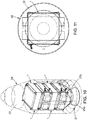
- a second example of satellite 100 is represented on the Figures 13 to 15 .
- the satellite 100 also comprises a body 102 having four faces called face 105 North, face 106 South, face 107 East, face 108 West, with reference to the terrestrial cardinal points, and two faces called faces 104 Earth and face 103 anti-Earth, with reference to the orientation of these faces with respect to the Earth.
- Equipment such as antennas 109, solar panels 110 shown folded on the faces 105 North and 106 South, are assembled on the body 102.
- Antennas 111 may also be provided on the face 104 Earth. This is for example a telecommunications satellite.
- the satellite 100 also comprises posts 112.
- the posts 112 are placed at the outer periphery of the body 102 of the satellite 100, and extend as previously in the same longitudinal direction A, perpendicular to the faces 105 North and 106 South. More specifically, according to this second example, two posts 112 are arranged against the face 104 Earth and two other posts are disposed against the face 103 anti-Earth.
- the arrangement of the posts 112 is a compromise between the bulk around the body 102 of the satellite 100 and the mechanical strength requirements of the stack of the satellites 100.
- the posts 112 are each provided with at least one, in practice two, each disposed at one end 13, 14 of a post 12, releasable locking devices 115 to allow the assembly of 100 satellites between them and possibly with a satellite interface structure 121 of a launcher 120.
- the satellite interface structure 121 may comprise two elements not shown, namely a lower cone launcher side and a side adapter. Satellites.
- Releasable locking devices 115 are substantially identical to those already described.
- the reinforcing structure 116 is substantially identical to that of the first example, and comprises branches 117 in the form of braces, connecting the posts 112 to each other through the geometric center C of the satellite body 102.
- the walls bearing the faces North 105, South 106, Earth 104, and anti-Earth 103 can either replace the branches 117 and form in themselves the reinforcing structure 116, or participate in the shear strength of the posts 112 as consolidation elements in shear.
- the stack of satellites 100 according to the second example is substantially identical to the stacks already described with reference to the first embodiment.
- the stacked satellites 100 face each other by their faces 105 North and 106 South, and can be oriented differently from each other around the longitudinal direction depending on the size and the space available under the cap 122 of the launcher 120.
- the satellite 1, 100 thus described makes it possible to envisage heterogeneous stacks, that is to say having more than one type of satellite.
- a launcher 220 it is possible to consider several satellites 1, 100, in this case five according to the example presented according to the figure 16 noted S1, S2, S3, S4, S5, from several production sites, denoted PROD1, PROD2, PROD3 and PROD4, and different from each other, and form the stack once at the launch site.
- the satellite S1 and the satellite S2 come from the same production site PROD1.
- the satellite S2 is itself formed by assembling the elements E1 and E2, which can be intended to be released later and separately in space.
- the production site PROD1 then provides a group comprising the satellite S1 stacked on the satellite S2, the devices 15, 115 for locking between the two satellites S1 and S2 then being in the locked state.
- the satellite S3 comes from the production site PROD2
- the satellite S4 comes from the production site PROD3
- the satellite S5 is formed of three elements E3, E4, E5 coming from the production site PROD4.
- On the launch site therefore, are the group comprising satellites S1 and S2, satellite S3, satellite S4 and satellite S5.
- the posts 12, 112 of the five satellites S1 to S5 may be different, but they are arranged to allow stacking.
- the satellite S4 is first locked on the satellite interface structure 221 of the launcher 220.
- the satellite S4 may be previously coupled with an adapter which will then be coupled, in the launcher, with a lower cone already installed in the launcher .
- a new group is formed outside the launcher 220, locking the satellite S5 under the group formed by the satellites S1 and S2.
- the new group of satellites S5, S2, S1 is then stacked on the satellite S4, in the launcher 220, by putting in the locked state the locking devices 15 between the satellite S4 and the satellite S5.
- the satellite S3 is locked on the satellite S1 of the new satellite group S5, S2, S1.
- the device for controlling the state of the locking devices can be either on board the launcher or comprise several modules each aboard one of the satellites S1 to S5 or a satellite of a group.
- the control can be programmed in the control device or emitted from the ground.
- the satellites S3 and S4 do not necessarily have a structure according to the invention comprising poles, but they nevertheless have compatible locking / unlocking means as well the ability to withstand the forces exerted during launch by the satellite stack with which they are interconnected.
- the stacking and assembly sequence in the launcher 220 can be adapted according to what is provided by the production sites and the order in which the satellites S1 to S5 are to be dropped into space.
- the satellites S1 to S5 can be released through the device of the state control of the locking devices.
- the satellite S3 is first dropped by passing in the unlocked state the locking devices between the satellite S3 and the satellite S1.
- the satellite group S5, S2, S1 can be dropped in block, by putting in the unlocked state the locking devices 15 between the satellite S4 and the satellite S5.
- the satellites S5, S2, S1 can then be separated later from each other once dropped in space.
- the satellite S4 is separated from the satellite interface structure 221.
- the latch state control device can program the satellite drop sequence in advance.
- the release sequence does not have to take into account possible balancing problems within the launcher.
- the space vehicle according to the invention is suitable for any type of space mission (telecommunications, navigation, space vehicles for earth observation, science, space exploration), whatever their orbit (LEO, GEO, MEO, HEO).
- Satellites of a constellation can also be dropped in groups (eg, orbital plane) or one by one.
- the space vehicle according to the invention is well suited for a mass of satellites generally 1 ton or more, but could also be applied, without loss of generality, to smaller satellites of a few kilograms, allowing to have one or several stacks located "side by side” under the launcher's cap.
Landscapes
- Engineering & Computer Science (AREA)
- Remote Sensing (AREA)
- Aviation & Aerospace Engineering (AREA)
- Physics & Mathematics (AREA)
- Astronomy & Astrophysics (AREA)
- General Physics & Mathematics (AREA)
- Details Of Aerials (AREA)
Claims (17)
- Weltraumfahrzeug (1, 100), wie etwa ein Satellit, das dazu bestimmt ist, in eine Umlaufbahn um einen Planeten gebracht zu werden, wobei das Fahrzeug (1, 100) Folgendes umfasst:- zumindest ein Ausrüstungsträgermodul (2, 102), das dazu bestimmt ist, Ausrüstungen des Fahrzeugs (1, 100) zu tragen;- zumindest drei Pfosten (12, 112), die sich zumindest teilweise in eine selbe Längsrichtung (A) und an der Peripherie des Ausrüstungsträgermoduls (2, 102) erstrecken;- eine Verstärkungsstruktur (16, 116), die jeden Pfosten (12, 112) mit zumindest zwei anderen Pfosten (12, 112) starr transversal verbindet,
dadurch gekennzeichnet, dass jeder Pfosten (12, 112) mit zumindest einer lösbaren Verriegelungsvorrichtung (15, 115) ausgestattet ist, die dazu bestimmt ist, zwei Zustände einzunehmen:∘ einen verriegelten Zustand, in dem die Verriegelungsvorrichtung (15, 115) an einer zusätzlichen Verriegelungsvorrichtung (15, 115) befestigt ist,∘ einen entriegelten Zustand, in dem die Verriegelungsvorrichtung (15, 115) von jeder anderen Verriegelungsvorrichtung (15, 115) gelöst ist. - Weltraumfahrzeug (1, 100) nach Anspruch 1, wobei die Verstärkungsstruktur (16, 116) zweigförmige Verstärkungselemente (17, 117) umfasst, deren Anzahl zumindest der Anzahl an Pfosten (12, 112) entspricht, wobei jeder Zweig (17, 117) zwischen zwei Pfosten (12, 112) befestigt ist.
- Weltraumfahrzeug (1, 100) nach Anspruch 2, wobei die Zweige (17, 117) mit Wänden des Ausrüstungsträgermoduls (2, 102) zusammenfallen, wobei die Wände Träger für Ausrüstungen des Fahrzeugs (1, 100) ausbilden.
- Weltraumfahrzeug (1, 100) nach Anspruch 1, wobei die Verstärkungsstruktur (16, 116) zweigförmige Verstärkungselemente (17, 117) umfasst, deren Anzahl zumindest der Anzahl an Pfosten (12, 112) entspricht, wobei jeder Zweig (17, 117) einerseits an einem Pfosten (12, 112) und andererseits an einem selben Befestigungszentrum (C) befestigt ist.
- Fahrzeug (1, 100) nach einem der Ansprüche 2 bis 4, wobei die Verstärkungszweige (17, 117) paarweise durch Konsolidierungselemente (19) in Scherung verbunden sind.
- Fahrzeug (1, 100) nach einem der vorangehenden Ansprüche, wobei die Anzahl der Pfosten (12, 112) drei beträgt und sie auf die Spitzen eines gleichseitigen Dreiecks aufgeteilt sind.
- Fahrzeug (1, 100) nach einem der Ansprüche 1 bis 5, wobei die Anzahl der Pfosten (12, 112) vier beträgt und sie auf die Spitzen eines Parallelogramms aufgeteilt sind.
- Fahrzeug (1, 100) nach einem der vorangehenden Ansprüche, wobei jede lösbare Verriegelungsvorrichtung (15, 115) ein magnetisches Element umfasst.
- Fahrzeug (1, 100) nach einem der vorangehenden Ansprüche, wobei jede lösbare Verriegelungsvorrichtung (15, 115) ein pyrotechnisches Element umfasst.
- Fahrzeug (1, 100) nach einem der vorangehenden Ansprüche, wobei jeder Pfosten (12, 112) mit zwei lösbaren Verriegelungsvorrichtungen (15, 115) ausgestattet ist.
- Fahrzeug (1, 100) nach einem der vorangehenden Ansprüche, wobei sich jeder Pfosten längs zwischen zwei Enden (13, 14) erstreckt, wobei jedes Ende (13, 14) mit einer Verriegelungsvorrichtung (15, 115) ausgestattet ist.
- Verfahren zur Montage von zumindest zwei Fahrzeugen (1, 100) nach einem der Ansprüche 1 bis 11, umfassend die folgenden Schritte:- Positionieren der zumindest zwei Fahrzeuge (1, 100), sodass sich die Pfosten (12, 112) eines ersten Fahrzeugs (1, 100) zumindest teilweise in eine selbe Längsrichtung wie die Pfosten (12, 112) des zweiten Fahrzeugs (1, 100) erstrecken;- In-Zusammenwirkung-Bringen jeder Verriegelungsvorrichtung (15, 115) des ersten Fahrzeugs (1, 100) mit einer Verriegelungsvorrichtung (15, 115) des zweiten Fahrzeugs (1, 100);- Versetzen der Verriegelungsvorrichtungen (15, 115) des ersten Fahrzeugs (1, 100) in den verriegelten Zustand an den Verriegelungsvorrichtungen (15, 115) des zweiten Fahrzeugs (1, 100).
- Stapel von Fahrzeugen (1, 100) nach einem der Ansprüche 1 bis 11, umfassend zumindest zwei miteinander verbundene Fahrzeuge (1, 100), wobei sich die zumindest eine lösbare Verriegelungsvorrichtung (15, 115) jedes Pfostens (12, 112) eines ersten Fahrzeugs (1, 100) im verriegelten Zustand mit einer Verriegelungsvorrichtung (15, 115) an einem Pfosten (12, 112) des zweiten Fahrzeugs (1, 100) befindet, wobei sich die Pfosten (12, 112) jedes Fahrzeugs in eine selbe Längsrichtung (A) erstrecken, wobei der Stapel ferner eine Vorrichtung zum Steuern des Zustands der Verriegelungsvorrichtungen (15, 115) umfasst.
- Stapel von Fahrzeugen (1, 100) nach Anspruch 13, wobei die Fahrzeuge (1, 100) Satelliten sind, die eine Erdseite (7, 104) und eine Erdgegenseite (8, 103) umfassen, wobei die Erdseite und die Erdgegenseite in der Längsrichtung (A) der Pfosten (12, 112) ausgerichtet sind.
- Stapel von Fahrzeugen nach Anspruch 13, wobei die Fahrzeuge (1, 100) Satelliten sind, die eine Erdseite (7, 104) und eine Erdgegenseite (8, 103) aufweisen, wobei die Erdseite (7, 104) und die Erdgegenseite (8, 103) in einer Querrichtung zu den Pfosten (12, 112) ausgerichtet sind.
- Trägerrakete (20, 120, 220) von Weltraumfahrzeugen (1, 100), wobei die Trägerrakete eine Fahrzeugschnittstellenstruktur (21, 121, 221) und zumindest einen ersten Stapel von Fahrzeugen (1, 100) nach einem der Ansprüche 13 bis 15 umfasst, wobei zumindest das erste Fahrzeug (1, 100) des Stapels ein Fahrzeug (1, 100) nach Anspruch 10 oder Anspruch 11 ist, wobei sich eine erste Verriegelungsvorrichtung (15, 115) jedes Pfostens (12, 112) des ersten Fahrzeugs (1, 100) im verriegelten Zustand an einer Verriegelungsvorrichtung (15, 115) des zweiten Fahrzeugs (1, 100) befindet, wobei sich die zweite Verriegelungsvorrichtung (15, 115) jedes Pfostens (12, 112) des ersten Fahrzeugs (1, 100) in einem verriegelten Zustand an der Fahrzeugschnittstellenstruktur (21, 121, 221) befindet.
- Verfahren zur Freigabe von Fahrzeugen (1, 100) mittels einer Trägerrakete (21, 121, 221) nach Anspruch 16, umfassend einen Schritt der Trennung zwischen einem Fahrzeug oder einer Gruppe von Fahrzeugen (1, 100), die freizugeben sind, und einem Fahrzeug (1, 100), das dazu bestimmt ist, in der Trägerrakete zu bleiben, durch Versetzen der Verriegelungsvorrichtungen (15, 115) zwischen den beiden Fahrzeugen bzw. einem Fahrzeug (1, 100) der Gruppe, die freizugeben sind, und dem Fahrzeug (1, 100), das dazu bestimmt ist, in der Trägerrakete (20, 120, 220) zu bleiben, in den entriegelten Zustand, um ein einziges Fahrzeug bzw. die Gruppe von Fahrzeugen (1, 100) freizugeben.
Applications Claiming Priority (2)
| Application Number | Priority Date | Filing Date | Title |
|---|---|---|---|
| FR1558695A FR3040978B1 (fr) | 2015-09-16 | 2015-09-16 | Vehicule spatial comprenant des poteaux pour former un empilement, empilement comprenant au moins deux tels vehicules places dans un lanceur et procede de largage des vehicules |
| PCT/FR2016/052287 WO2017046497A1 (fr) | 2015-09-16 | 2016-09-12 | Véhicule spatial comprenant des poteaux pour former un empilement, empilement comprenant au moins deux tels véhicules placés dans un lanceur et procédé de largage des véhicules |
Publications (2)
| Publication Number | Publication Date |
|---|---|
| EP3259190A1 EP3259190A1 (de) | 2017-12-27 |
| EP3259190B1 true EP3259190B1 (de) | 2018-07-18 |
Family
ID=54979732
Family Applications (1)
| Application Number | Title | Priority Date | Filing Date |
|---|---|---|---|
| EP16775300.3A Active EP3259190B1 (de) | 2015-09-16 | 2016-09-12 | Weltraumfahrzeug mit pfosten zur bildung eines stapels, stapel mit mindestens zwei solchen fahrzeugen in einer trägerrakete und verfahren zur freigabe der fahrzeuge |
Country Status (6)
| Country | Link |
|---|---|
| US (1) | US10017279B2 (de) |
| EP (1) | EP3259190B1 (de) |
| JP (1) | JP6448855B2 (de) |
| CN (1) | CN108137172B (de) |
| FR (1) | FR3040978B1 (de) |
| WO (1) | WO2017046497A1 (de) |
Families Citing this family (32)
| Publication number | Priority date | Publication date | Assignee | Title |
|---|---|---|---|---|
| US10351268B2 (en) * | 2016-12-08 | 2019-07-16 | The Boeing Company | Systems and methods for deploying spacecraft |
| US11072441B2 (en) * | 2017-03-03 | 2021-07-27 | Northrop Grumman Systems Corporation | Stackable spacecraft |
| US10981679B2 (en) | 2017-08-04 | 2021-04-20 | Rocket Lab Usa, Inc. | Satellite deployer door release mechanism |
| AU2018375992B2 (en) * | 2017-12-01 | 2024-06-13 | D-ORBIT S.p.A. | Method of releasing artificial satellites in earth's orbit |
| KR102002306B1 (ko) * | 2018-01-08 | 2019-07-22 | 주식회사 버츄얼랩 | 큐브위성 우주 분리장치 |
| RO133557B1 (ro) * | 2018-02-19 | 2020-11-27 | Mazarom Impex S.R.L. | Satelit artificial cu dimensiuni reduse |
| IL258729B (en) * | 2018-04-16 | 2021-12-01 | Israel Aerospace Ind Ltd | Nano-satellite |
| WO2019223984A1 (en) * | 2018-05-24 | 2019-11-28 | The European Union, Represented By The European Commission | Efficient satellite structure concept for single or stacking multiple launches |
| FR3085157B1 (fr) * | 2018-08-23 | 2020-11-06 | Airbus Defence & Space Sas | Vehicule spatial, lanceur et empilement de vehicules spatiaux |
| US11505338B2 (en) * | 2019-02-22 | 2022-11-22 | The Boeing Company | Systems and methods for launching a plurality of spacecraft |
| US11858667B1 (en) * | 2019-10-16 | 2024-01-02 | Amazon Technologies, Inc. | Satellite dispenser |
| CN111332496B (zh) * | 2020-03-03 | 2023-05-05 | 陕西智星空间科技有限公司 | 卫星发射方法及卫星固定装置 |
| CN111332495B (zh) * | 2020-03-03 | 2023-08-08 | 陕西智星空间科技有限公司 | 板状卫星组合体及其发射方法 |
| CN111609884B (zh) * | 2020-05-21 | 2022-04-08 | 齐齐哈尔大学 | 一种沙漠监测系统及其操作方法 |
| CN111674567A (zh) * | 2020-06-18 | 2020-09-18 | 中国科学院微小卫星创新研究院 | 一种星座卫星的构型 |
| US11492147B2 (en) * | 2020-07-30 | 2022-11-08 | The Aerospace Corporation | Stackable satellite structure and deployment method |
| CN112193441B (zh) * | 2020-09-29 | 2021-11-30 | 哈尔滨工业大学 | 一种太空中多卫星锁紧弹射机构 |
| CN112319853B (zh) * | 2020-11-16 | 2021-09-24 | 三亚中科遥感研究所 | 一种适应圆柱形整流罩空间一箭多星发射的微小卫星构型设计 |
| CN112693638B (zh) * | 2021-01-07 | 2023-02-28 | 航天行云科技有限公司 | 一种多星串联堆叠结构及固定与分离控制装置 |
| CN113581499B (zh) * | 2021-08-06 | 2023-02-17 | 长光卫星技术股份有限公司 | 一种堆叠式卫星联动解锁分离装置 |
| US11649074B1 (en) | 2021-08-12 | 2023-05-16 | Blue Origin, Llc | Satellite dispensing system |
| CN113619812A (zh) * | 2021-09-10 | 2021-11-09 | 赛德雷特(珠海)航天科技有限公司 | 一种标准模块化微小卫星系统 |
| CN113665844B (zh) * | 2021-09-10 | 2023-09-19 | 上海卫星工程研究所 | 用于堆叠卫星与运载分离的星箭解锁装置 |
| ES3063606T3 (en) * | 2021-11-10 | 2026-04-17 | Beyond Gravity Sweden Ab | A separable clamped hdrm interface for managing torsion loads |
| CN114537710A (zh) * | 2022-01-18 | 2022-05-27 | 上海卫星工程研究所 | 柔性太阳电池阵压紧装置、工作方法及卫星 |
| US20250197033A1 (en) * | 2022-04-12 | 2025-06-19 | Ascendarc, Inc. | A Satellite Designed to be Stacked and Launched in Groups |
| CN115196052B (zh) * | 2022-07-13 | 2024-12-17 | 航天行云科技有限公司 | 一种堆叠式卫星的固定装置及其控制方法 |
| FR3139802B1 (fr) | 2022-09-20 | 2024-08-23 | Airbus Defence & Space Sas | empilement d’engins spatiaux |
| US11987394B2 (en) * | 2022-09-23 | 2024-05-21 | Maxar Space Llc | Multi-spacecraft deployment |
| CN115743627B (zh) * | 2022-10-31 | 2025-08-01 | 北京宇航系统工程研究所 | 一种适用于多种载荷同时抛撒的自解锁推力抛撒装置 |
| FR3149873A1 (fr) * | 2023-06-15 | 2024-12-20 | Thales | Système d'attache d'un satellite |
| US20260035106A1 (en) * | 2024-08-02 | 2026-02-05 | Macdonald, Dettwiler And Associates Corporation | Spacecraft platform structure |
Citations (1)
| Publication number | Priority date | Publication date | Assignee | Title |
|---|---|---|---|---|
| EP3012194A1 (de) * | 2014-10-24 | 2016-04-27 | Thales | Bedienung eines satelliten im weltraum |
Family Cites Families (16)
| Publication number | Priority date | Publication date | Assignee | Title |
|---|---|---|---|---|
| US5199672A (en) * | 1990-05-25 | 1993-04-06 | Orbital Sciences Corporation | Method and apparatus for deploying a satellite network |
| US5411226A (en) * | 1993-10-13 | 1995-05-02 | Martin Marietta Corporation | Spacecraft adapter and dispenser |
| US5522569A (en) * | 1994-02-04 | 1996-06-04 | Orbital Sciences Corporation | Satellite having a stackable configuration |
| US5605308A (en) | 1994-06-06 | 1997-02-25 | Mcdonnell Douglas Corp. | Space vehicle dispenser |
| FR2735099B1 (fr) | 1995-06-06 | 1997-08-29 | Aerospatiale | Dispositif adaptateur basculant pour l'emport de plusieurs charges utiles sur un meme lanceur. |
| US5884866A (en) * | 1996-09-17 | 1999-03-23 | Mcdonnell Douglas Corporation | Satellite dispenser |
| US6138951A (en) * | 1998-08-10 | 2000-10-31 | Mcdonnell Douglas Corporation | Spacecraft dispensing system |
| DE19856670B4 (de) | 1998-12-09 | 2004-12-02 | Eads Space Transportation Gmbh | Vorrichtung zum Aussetzen von Satelliten |
| US7832687B1 (en) | 2004-08-24 | 2010-11-16 | Lockheed Martin Corporation | On-orbit storage, plane change, and injection to final orbit of space vehicles |
| US20080078886A1 (en) * | 2006-08-22 | 2008-04-03 | The Boeing Company | Launch vehicle cargo carrier |
| US8016240B2 (en) | 2007-03-29 | 2011-09-13 | The Boeing Company | Satellites and satellite fleet implementation methods and apparatus |
| FR2954284B1 (fr) * | 2009-12-18 | 2012-05-04 | Thales Sa | Dispositif de deploiement et de pointage d'elements structurants dans un environnement spatial |
| US8939409B2 (en) | 2012-05-07 | 2015-01-27 | The Johns Hopkins University | Adaptor system for deploying small satellites |
| US8915472B2 (en) | 2012-05-11 | 2014-12-23 | The Boeing Company | Multiple space vehicle launch system |
| CN103303494B (zh) * | 2013-05-30 | 2016-02-17 | 西北工业大学 | 具有自搭载发射功能的新型纳卫星结构 |
| US9663249B2 (en) * | 2014-02-14 | 2017-05-30 | Carey LIVELY | Dual spacecraft design and deployment system and method of use thereof |
-
2015
- 2015-09-16 FR FR1558695A patent/FR3040978B1/fr not_active Expired - Fee Related
-
2016
- 2016-09-12 US US15/564,816 patent/US10017279B2/en active Active
- 2016-09-12 EP EP16775300.3A patent/EP3259190B1/de active Active
- 2016-09-12 WO PCT/FR2016/052287 patent/WO2017046497A1/fr not_active Ceased
- 2016-09-12 CN CN201680059293.8A patent/CN108137172B/zh active Active
- 2016-09-12 JP JP2018513521A patent/JP6448855B2/ja active Active
Patent Citations (1)
| Publication number | Priority date | Publication date | Assignee | Title |
|---|---|---|---|---|
| EP3012194A1 (de) * | 2014-10-24 | 2016-04-27 | Thales | Bedienung eines satelliten im weltraum |
Also Published As
| Publication number | Publication date |
|---|---|
| JP6448855B2 (ja) | 2019-01-09 |
| US20180111707A1 (en) | 2018-04-26 |
| CN108137172A (zh) | 2018-06-08 |
| CN108137172B (zh) | 2021-02-05 |
| WO2017046497A1 (fr) | 2017-03-23 |
| FR3040978A1 (fr) | 2017-03-17 |
| JP2018527243A (ja) | 2018-09-20 |
| FR3040978B1 (fr) | 2017-10-06 |
| US10017279B2 (en) | 2018-07-10 |
| EP3259190A1 (de) | 2017-12-27 |
Similar Documents
| Publication | Publication Date | Title |
|---|---|---|
| EP3259190B1 (de) | Weltraumfahrzeug mit pfosten zur bildung eines stapels, stapel mit mindestens zwei solchen fahrzeugen in einer trägerrakete und verfahren zur freigabe der fahrzeuge | |
| EP2563670B1 (de) | Satellit mit vereinfachter struktur, geringem gewicht und kostengünstig, und das dazugehörige anwendungsverfahren | |
| EP3313734B1 (de) | Satellit mit zylindrischem hauptkörper, stapel mit solch einem satelliten und startanordnung für solch einen satelliten | |
| EP3081496B1 (de) | Verfahren zur ausstattung einer vielzahl von raumfahrzeugen unter der nutzlastverkleidung einer trägerrakete, aus diesem verfahren hervorgehende montage und geeigneter dispenser für eine solche montage | |
| EP3807152B1 (de) | Anordnung von raumfahrzeugen | |
| EP2468630B1 (de) | Entfaltbare Struktur, die eine mit einem Sonnenenergiegenerator ausgestattete Antenne für einen Satelliten bildet | |
| EP2514674B1 (de) | Schutzvorrichtung für ein optisches Instrument eines Satelliten | |
| FR2748256A1 (fr) | Ensemble de satellite(s) comportant des composantes de plate-forme modulaires communes et procede de mise en orbite de tels ensembles | |
| EP2983991A1 (de) | Satellitensystem mit zwei miteinander verbundenen satelliten und verfahren zum abschuss davon in den orbit | |
| FR2652642A1 (fr) | Missile de largage de sous-munitions equipe d'un conteneur modulable. | |
| WO2014131990A2 (fr) | Module de propulsion spatiale a propulsion electrique et chimique a propergol solide | |
| EP2143639B1 (de) | Verfahren zum Verringern der mitgeführten Treibstoffmasse bei einer interplanetaren Mission | |
| WO2010026345A2 (fr) | Structure d'ensemble siège pour aéronef et fuselage adapté | |
| FR3120230A1 (fr) | Système de chariot mobile et procédé de mise en œuvre d’un système de chariot mobile | |
| EP4590584B1 (de) | Raumfahrzeugstapel | |
| EP2962942B1 (de) | Satellit mit variabler stirnfläche | |
| EP3959141A1 (de) | Entfaltbare struktur mit grossen abmessungen | |
| EP3305667B1 (de) | Stapelvorrichtung für raumfahrzeug, und entsprechendes raumfahrzeug | |
| FR3163352A1 (fr) | Module spatial destiné à être déployé dans l’espace pour former une plateforme spatiale et plateforme spatiale associée | |
| EP4663557A1 (de) | Verfahren zur steuerung einer räumlichen plattform und zugehöriges steuerungssystem | |
| FR3163351A1 (fr) | Plateforme spatiale et procédé de déploiement d’une telle plateforme |
Legal Events
| Date | Code | Title | Description |
|---|---|---|---|
| STAA | Information on the status of an ep patent application or granted ep patent |
Free format text: STATUS: THE INTERNATIONAL PUBLICATION HAS BEEN MADE |
|
| PUAI | Public reference made under article 153(3) epc to a published international application that has entered the european phase |
Free format text: ORIGINAL CODE: 0009012 |
|
| STAA | Information on the status of an ep patent application or granted ep patent |
Free format text: STATUS: REQUEST FOR EXAMINATION WAS MADE |
|
| 17P | Request for examination filed |
Effective date: 20170920 |
|
| AK | Designated contracting states |
Kind code of ref document: A1 Designated state(s): AL AT BE BG CH CY CZ DE DK EE ES FI FR GB GR HR HU IE IS IT LI LT LU LV MC MK MT NL NO PL PT RO RS SE SI SK SM TR |
|
| AX | Request for extension of the european patent |
Extension state: BA ME |
|
| GRAP | Despatch of communication of intention to grant a patent |
Free format text: ORIGINAL CODE: EPIDOSNIGR1 |
|
| STAA | Information on the status of an ep patent application or granted ep patent |
Free format text: STATUS: GRANT OF PATENT IS INTENDED |
|
| RIN1 | Information on inventor provided before grant (corrected) |
Inventor name: PRUD HON, CHRISTOPHE Inventor name: PONCET, DOMINIQUE Inventor name: GUYOT, SERGE |
|
| DAV | Request for validation of the european patent (deleted) | ||
| DAX | Request for extension of the european patent (deleted) | ||
| INTG | Intention to grant announced |
Effective date: 20180313 |
|
| GRAS | Grant fee paid |
Free format text: ORIGINAL CODE: EPIDOSNIGR3 |
|
| GRAA | (expected) grant |
Free format text: ORIGINAL CODE: 0009210 |
|
| STAA | Information on the status of an ep patent application or granted ep patent |
Free format text: STATUS: THE PATENT HAS BEEN GRANTED |
|
| AK | Designated contracting states |
Kind code of ref document: B1 Designated state(s): AL AT BE BG CH CY CZ DE DK EE ES FI FR GB GR HR HU IE IS IT LI LT LU LV MC MK MT NL NO PL PT RO RS SE SI SK SM TR |
|
| REG | Reference to a national code |
Ref country code: GB Ref legal event code: FG4D Free format text: NOT ENGLISH |
|
| REG | Reference to a national code |
Ref country code: CH Ref legal event code: EP |
|
| REG | Reference to a national code |
Ref country code: IE Ref legal event code: FG4D Free format text: LANGUAGE OF EP DOCUMENT: FRENCH |
|
| REG | Reference to a national code |
Ref country code: AT Ref legal event code: REF Ref document number: 1019056 Country of ref document: AT Kind code of ref document: T Effective date: 20180815 |
|
| REG | Reference to a national code |
Ref country code: DE Ref legal event code: R096 Ref document number: 602016004167 Country of ref document: DE |
|
| REG | Reference to a national code |
Ref country code: FR Ref legal event code: PLFP Year of fee payment: 3 |
|
| RAP2 | Party data changed (patent owner data changed or rights of a patent transferred) |
Owner name: AIRBUS DEFENCE AND SPACE SAS |
|
| REG | Reference to a national code |
Ref country code: DE Ref legal event code: R081 Ref document number: 602016004167 Country of ref document: DE Owner name: AIRBUS DEFENCE AND SPACE SAS, FR Free format text: FORMER OWNER: AIRBUS DEFENCE AND SPACE SAS, LES MUREAUX, FR |
|
| REG | Reference to a national code |
Ref country code: NL Ref legal event code: MP Effective date: 20180718 |
|
| REG | Reference to a national code |
Ref country code: LT Ref legal event code: MG4D |
|
| REG | Reference to a national code |
Ref country code: AT Ref legal event code: MK05 Ref document number: 1019056 Country of ref document: AT Kind code of ref document: T Effective date: 20180718 |
|
| PG25 | Lapsed in a contracting state [announced via postgrant information from national office to epo] |
Ref country code: NL Free format text: LAPSE BECAUSE OF FAILURE TO SUBMIT A TRANSLATION OF THE DESCRIPTION OR TO PAY THE FEE WITHIN THE PRESCRIBED TIME-LIMIT Effective date: 20180718 |
|
| PG25 | Lapsed in a contracting state [announced via postgrant information from national office to epo] |
Ref country code: AT Free format text: LAPSE BECAUSE OF FAILURE TO SUBMIT A TRANSLATION OF THE DESCRIPTION OR TO PAY THE FEE WITHIN THE PRESCRIBED TIME-LIMIT Effective date: 20180718 Ref country code: IS Free format text: LAPSE BECAUSE OF FAILURE TO SUBMIT A TRANSLATION OF THE DESCRIPTION OR TO PAY THE FEE WITHIN THE PRESCRIBED TIME-LIMIT Effective date: 20181118 Ref country code: LT Free format text: LAPSE BECAUSE OF FAILURE TO SUBMIT A TRANSLATION OF THE DESCRIPTION OR TO PAY THE FEE WITHIN THE PRESCRIBED TIME-LIMIT Effective date: 20180718 Ref country code: GR Free format text: LAPSE BECAUSE OF FAILURE TO SUBMIT A TRANSLATION OF THE DESCRIPTION OR TO PAY THE FEE WITHIN THE PRESCRIBED TIME-LIMIT Effective date: 20181019 Ref country code: RS Free format text: LAPSE BECAUSE OF FAILURE TO SUBMIT A TRANSLATION OF THE DESCRIPTION OR TO PAY THE FEE WITHIN THE PRESCRIBED TIME-LIMIT Effective date: 20180718 Ref country code: NO Free format text: LAPSE BECAUSE OF FAILURE TO SUBMIT A TRANSLATION OF THE DESCRIPTION OR TO PAY THE FEE WITHIN THE PRESCRIBED TIME-LIMIT Effective date: 20181018 Ref country code: BG Free format text: LAPSE BECAUSE OF FAILURE TO SUBMIT A TRANSLATION OF THE DESCRIPTION OR TO PAY THE FEE WITHIN THE PRESCRIBED TIME-LIMIT Effective date: 20181018 Ref country code: SE Free format text: LAPSE BECAUSE OF FAILURE TO SUBMIT A TRANSLATION OF THE DESCRIPTION OR TO PAY THE FEE WITHIN THE PRESCRIBED TIME-LIMIT Effective date: 20180718 Ref country code: PL Free format text: LAPSE BECAUSE OF FAILURE TO SUBMIT A TRANSLATION OF THE DESCRIPTION OR TO PAY THE FEE WITHIN THE PRESCRIBED TIME-LIMIT Effective date: 20180718 Ref country code: FI Free format text: LAPSE BECAUSE OF FAILURE TO SUBMIT A TRANSLATION OF THE DESCRIPTION OR TO PAY THE FEE WITHIN THE PRESCRIBED TIME-LIMIT Effective date: 20180718 |
|
| PG25 | Lapsed in a contracting state [announced via postgrant information from national office to epo] |
Ref country code: AL Free format text: LAPSE BECAUSE OF FAILURE TO SUBMIT A TRANSLATION OF THE DESCRIPTION OR TO PAY THE FEE WITHIN THE PRESCRIBED TIME-LIMIT Effective date: 20180718 Ref country code: LV Free format text: LAPSE BECAUSE OF FAILURE TO SUBMIT A TRANSLATION OF THE DESCRIPTION OR TO PAY THE FEE WITHIN THE PRESCRIBED TIME-LIMIT Effective date: 20180718 Ref country code: HR Free format text: LAPSE BECAUSE OF FAILURE TO SUBMIT A TRANSLATION OF THE DESCRIPTION OR TO PAY THE FEE WITHIN THE PRESCRIBED TIME-LIMIT Effective date: 20180718 |
|
| REG | Reference to a national code |
Ref country code: DE Ref legal event code: R097 Ref document number: 602016004167 Country of ref document: DE |
|
| PG25 | Lapsed in a contracting state [announced via postgrant information from national office to epo] |
Ref country code: MC Free format text: LAPSE BECAUSE OF FAILURE TO SUBMIT A TRANSLATION OF THE DESCRIPTION OR TO PAY THE FEE WITHIN THE PRESCRIBED TIME-LIMIT Effective date: 20180718 Ref country code: RO Free format text: LAPSE BECAUSE OF FAILURE TO SUBMIT A TRANSLATION OF THE DESCRIPTION OR TO PAY THE FEE WITHIN THE PRESCRIBED TIME-LIMIT Effective date: 20180718 Ref country code: CZ Free format text: LAPSE BECAUSE OF FAILURE TO SUBMIT A TRANSLATION OF THE DESCRIPTION OR TO PAY THE FEE WITHIN THE PRESCRIBED TIME-LIMIT Effective date: 20180718 Ref country code: EE Free format text: LAPSE BECAUSE OF FAILURE TO SUBMIT A TRANSLATION OF THE DESCRIPTION OR TO PAY THE FEE WITHIN THE PRESCRIBED TIME-LIMIT Effective date: 20180718 Ref country code: ES Free format text: LAPSE BECAUSE OF FAILURE TO SUBMIT A TRANSLATION OF THE DESCRIPTION OR TO PAY THE FEE WITHIN THE PRESCRIBED TIME-LIMIT Effective date: 20180718 |
|
| PLBE | No opposition filed within time limit |
Free format text: ORIGINAL CODE: 0009261 |
|
| STAA | Information on the status of an ep patent application or granted ep patent |
Free format text: STATUS: NO OPPOSITION FILED WITHIN TIME LIMIT |
|
| PG25 | Lapsed in a contracting state [announced via postgrant information from national office to epo] |
Ref country code: SM Free format text: LAPSE BECAUSE OF FAILURE TO SUBMIT A TRANSLATION OF THE DESCRIPTION OR TO PAY THE FEE WITHIN THE PRESCRIBED TIME-LIMIT Effective date: 20180718 Ref country code: SK Free format text: LAPSE BECAUSE OF FAILURE TO SUBMIT A TRANSLATION OF THE DESCRIPTION OR TO PAY THE FEE WITHIN THE PRESCRIBED TIME-LIMIT Effective date: 20180718 Ref country code: DK Free format text: LAPSE BECAUSE OF FAILURE TO SUBMIT A TRANSLATION OF THE DESCRIPTION OR TO PAY THE FEE WITHIN THE PRESCRIBED TIME-LIMIT Effective date: 20180718 |
|
| REG | Reference to a national code |
Ref country code: BE Ref legal event code: MM Effective date: 20180930 |
|
| 26N | No opposition filed |
Effective date: 20190423 |
|
| REG | Reference to a national code |
Ref country code: IE Ref legal event code: MM4A |
|
| PG25 | Lapsed in a contracting state [announced via postgrant information from national office to epo] |
Ref country code: IE Free format text: LAPSE BECAUSE OF NON-PAYMENT OF DUE FEES Effective date: 20180912 |
|
| PG25 | Lapsed in a contracting state [announced via postgrant information from national office to epo] |
Ref country code: BE Free format text: LAPSE BECAUSE OF NON-PAYMENT OF DUE FEES Effective date: 20180930 Ref country code: SI Free format text: LAPSE BECAUSE OF FAILURE TO SUBMIT A TRANSLATION OF THE DESCRIPTION OR TO PAY THE FEE WITHIN THE PRESCRIBED TIME-LIMIT Effective date: 20180718 |
|
| PG25 | Lapsed in a contracting state [announced via postgrant information from national office to epo] |
Ref country code: MT Free format text: LAPSE BECAUSE OF FAILURE TO SUBMIT A TRANSLATION OF THE DESCRIPTION OR TO PAY THE FEE WITHIN THE PRESCRIBED TIME-LIMIT Effective date: 20180718 |
|
| PG25 | Lapsed in a contracting state [announced via postgrant information from national office to epo] |
Ref country code: TR Free format text: LAPSE BECAUSE OF FAILURE TO SUBMIT A TRANSLATION OF THE DESCRIPTION OR TO PAY THE FEE WITHIN THE PRESCRIBED TIME-LIMIT Effective date: 20180718 |
|
| PG25 | Lapsed in a contracting state [announced via postgrant information from national office to epo] |
Ref country code: PT Free format text: LAPSE BECAUSE OF FAILURE TO SUBMIT A TRANSLATION OF THE DESCRIPTION OR TO PAY THE FEE WITHIN THE PRESCRIBED TIME-LIMIT Effective date: 20180718 |
|
| REG | Reference to a national code |
Ref country code: CH Ref legal event code: PL |
|
| PG25 | Lapsed in a contracting state [announced via postgrant information from national office to epo] |
Ref country code: HU Free format text: LAPSE BECAUSE OF FAILURE TO SUBMIT A TRANSLATION OF THE DESCRIPTION OR TO PAY THE FEE WITHIN THE PRESCRIBED TIME-LIMIT; INVALID AB INITIO Effective date: 20160912 Ref country code: CY Free format text: LAPSE BECAUSE OF FAILURE TO SUBMIT A TRANSLATION OF THE DESCRIPTION OR TO PAY THE FEE WITHIN THE PRESCRIBED TIME-LIMIT Effective date: 20180718 Ref country code: MK Free format text: LAPSE BECAUSE OF NON-PAYMENT OF DUE FEES Effective date: 20180718 |
|
| PG25 | Lapsed in a contracting state [announced via postgrant information from national office to epo] |
Ref country code: CH Free format text: LAPSE BECAUSE OF NON-PAYMENT OF DUE FEES Effective date: 20190930 Ref country code: LI Free format text: LAPSE BECAUSE OF NON-PAYMENT OF DUE FEES Effective date: 20190930 |
|
| PGFP | Annual fee paid to national office [announced via postgrant information from national office to epo] |
Ref country code: DE Payment date: 20250919 Year of fee payment: 10 |
|
| PGFP | Annual fee paid to national office [announced via postgrant information from national office to epo] |
Ref country code: IT Payment date: 20250923 Year of fee payment: 10 Ref country code: LU Payment date: 20250919 Year of fee payment: 10 |
|
| PGFP | Annual fee paid to national office [announced via postgrant information from national office to epo] |
Ref country code: GB Payment date: 20250919 Year of fee payment: 10 |
|
| PGFP | Annual fee paid to national office [announced via postgrant information from national office to epo] |
Ref country code: FR Payment date: 20250922 Year of fee payment: 10 |