EP3305667B1 - Stapelvorrichtung für raumfahrzeug, und entsprechendes raumfahrzeug - Google Patents
Stapelvorrichtung für raumfahrzeug, und entsprechendes raumfahrzeug Download PDFInfo
- Publication number
- EP3305667B1 EP3305667B1 EP17194966.2A EP17194966A EP3305667B1 EP 3305667 B1 EP3305667 B1 EP 3305667B1 EP 17194966 A EP17194966 A EP 17194966A EP 3305667 B1 EP3305667 B1 EP 3305667B1
- Authority
- EP
- European Patent Office
- Prior art keywords
- space
- appendages
- hold down
- stacking
- release mechanisms
- Prior art date
- Legal status (The legal status is an assumption and is not a legal conclusion. Google has not performed a legal analysis and makes no representation as to the accuracy of the status listed.)
- Active
Links
Images



Classifications
-
- B—PERFORMING OPERATIONS; TRANSPORTING
- B64—AIRCRAFT; AVIATION; COSMONAUTICS
- B64G—COSMONAUTICS; VEHICLES OR EQUIPMENT THEREFOR
- B64G1/00—Cosmonautic vehicles
- B64G1/22—Parts of, or equipment specially adapted for fitting in or to, cosmonautic vehicles
- B64G1/222—Parts of, or equipment specially adapted for fitting in or to, cosmonautic vehicles for deploying structures between a stowed and deployed state
- B64G1/2228—Parts of, or equipment specially adapted for fitting in or to, cosmonautic vehicles for deploying structures between a stowed and deployed state characterised by the hold-down or release mechanisms
-
- B—PERFORMING OPERATIONS; TRANSPORTING
- B64—AIRCRAFT; AVIATION; COSMONAUTICS
- B64G—COSMONAUTICS; VEHICLES OR EQUIPMENT THEREFOR
- B64G1/00—Cosmonautic vehicles
- B64G1/22—Parts of, or equipment specially adapted for fitting in or to, cosmonautic vehicles
- B64G1/42—Arrangements or adaptations of power supply systems
- B64G1/44—Arrangements or adaptations of power supply systems using radiation, e.g. deployable solar arrays
- B64G1/443—Photovoltaic cell arrays
Definitions
- the present invention relates to the space field.
- the invention relates more particularly to a stacking device and an associated space vehicle.
- Space vehicles or vehicles such as, but not limited to, satellites or orbital stations orbiting the earth include space equipment intended to be deployed in space.
- this equipment will be called “space appendages”.
- spatial appendages is meant solar generators, antennas, reflectors, masts mirrors or any other equivalent equipment.
- a space appendix holding and release mechanism is mainly composed of an ejection system and a stacking tie rod tensioned in a stacking nut intended to be fixed to the body of the space vehicle.
- the space appendages are held on a support of the space vehicle, for example one face of the latter, by at least three stacking points.
- each appendix is held by four other holding and release mechanisms.
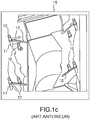
- the figures 1a, 1b and 1 C show an example of a face 15 of a satellite on which are stacked two spatial appendages, namely two antenna reflectors R1, R2.
- Each reflector is held on the satellite body by a stacking device comprising four different holding and release mechanisms 10.
- the reflector R2 closest to the satellite is held, temporarily, by stacking points 10 directly attached to the face 15 of the satellite.
- the reflector R1 furthest from the face 15 of the satellite is maintained by four other stacking points a little more on the periphery and raised compared to the four previous stacking points by extensions 11. Due to their height, these stacking points 10 risers are more bulky.
- these extensions are provided with reinforcing bars 12 which further increases their size, their mass and the cost of the stacking device.
- These extensions 11 and reinforcement bars 12 also add new constraints on the placement of the holding and release mechanisms 10 during the design phase of the satellite. Indeed, these stacking points must be placed so that during the mission, when the reflectors R1, R2 are deployed, the resident part of the holding and release mechanisms 10, namely the stacking nuts, do not enter into the field of view of the radiating sources 13 with which the antenna reflectors R1, R2 cooperate.
- the extensions 11 reinforcement bars 12 and other additional devices must also be placed so as not to hinder the deployment of the reflectors R1, R2 after the launch and the positioning of the space vehicle.
- the width of the space vehicle must be increased to allow the positioning of the various stacking points without interference.
- the taking into account of these constraints brings the support structures 20 (or “ backing structure ” according to the English terminology) of the spatial appendages to be found beyond the structure. 21 of the space vehicle. It is therefore impossible to position the holding and release mechanisms 10 on the space vehicle unless cantilever devices are attached to the structure 21 of the vehicle, intended to receive the holding and release mechanisms 10. which poses new problems of mass, bulk and fragility.
- the number of appendages attached to the same face of the space vehicle is generally limited to two.
- An object of the invention is in particular to correct all or part of the drawbacks of the prior art by proposing a solution making it possible to stack two or more space appendages on the same face of a space vehicle while having a reduced number of HRMs compared to current solutions.
- the invention relates to a stacking device for a space vehicle according to claim 1, said device comprising a plurality of holding and release mechanisms and being configured to temporarily hold n space appendages, n being , in this context, an integer strictly greater than 2, on the same support of a space vehicle using the holding and release mechanisms, said stacking device being configured so that several space appendages are held by one and the same holding and release mechanism.
- the same maintenance and release mechanism is configured to maintain two spatial appendages.
- each spatial appendix is maintained by four maintenance and release mechanisms.
- the maintenance and release mechanisms are located on a circle centered on the center of the spatial appendages.
- the maintenance and release mechanisms are arranged at the periphery of the spatial appendages.
- At least one maintenance and release mechanism passes through at least one spatial appendage.
- the subject of the invention is also a space vehicle comprising n space appendages, n being an integer strictly greater than two, said space vehicle comprising at least one stacking device, as defined above, configured to temporarily keep the space appendages on one and the same. front of the space vehicle.
- the principle of the invention is based on the use of retention and release mechanisms common to several spatial appendages in a stacking device in order to temporarily fix a number strictly greater than two, of spatial appendages on the same face. spacecraft or vehicle.
- the space vehicle is an artificial satellite.
- the figure 3 represents an example of a configuration in which n space appendages, n representing an integer strictly greater than 2, are partially superimposed and fixed temporarily on the same face of the space vehicle.
- n space appendages representing an integer strictly greater than 2
- the support structures 20 of the spatial appendages are shown.
- the space appendages, and therefore their support structure 20 are stacked on top of each other and are held temporarily on a support of the space vehicle, positioned, for example, on one face of the latter, using retention and release mechanisms 10.
- At least two spatial appendages can be maintained, temporarily, by the same maintenance and release mechanism 10.
- the use of maintenance and release mechanisms 10 common to several space appendages advantageously makes it possible to reduce the number. maintenance and release mechanisms to be used and therefore reduce the mass attached to the faces of the space vehicle. This makes it possible, also advantageously, to obtain more compact configurations.
- the holding and release mechanism 10 is dimensioned for n-1 space appendages, among the n space appendages mounted on the same support of the space vehicle.
- the same holding and release mechanism 10 will advantageously only be dimensioned for loads corresponding to only 3 appendages.
- Another advantage lies in the fact that, according to the invention, all the holding and release mechanisms 10 are of identical shape and have the same height. As a result, during the qualification phase of the maintenance and release mechanisms, the qualification of only one of these mechanisms will be sufficient.
- each space appendix is temporarily held on a support of the space vehicle using four retaining and release mechanisms 10 passing through sockets (not shown) fixed on the support structure 20 of each space appendix. These sockets allow the passage of the stacking tie rod.
- the holding and release mechanisms 10 may be disposed at the periphery of the spatial appendages.
- this arrangement makes it possible to facilitate access to the spatial appendages during the assembly, integration and test phases.
- At least one maintenance and release mechanism 10 can pass through at least one spatial appendage in its central part.
- the holding and release mechanisms 10 can be arranged in a common overlap area with the appendages in order to fix the spatial appendages together.
- the spatial appendages can be stacked concentrically and the holding and release mechanisms can be distributed over a circle C whose center is substantially aligned with that of the circle which circumscribes the stack of different spatial appendages.
- the radius of the circle C, on which the holding and release mechanisms 10 are aligned does not depend on the number of stacked space appendages, but only on that on which the sleeves are arranged on the support structure. 20 of each spatial appendix.
- the sockets intended to be traversed by the holding and release mechanisms, can be distributed in an irregular or patatoidal arrangement.
- the holding and release mechanisms 10 can be distributed uniformly over the structure 21 of the space vehicle. These retaining and releasing mechanisms 10 can, for example, be distributed evenly over a circle.
- the sockets of each space appendage can be arranged in a substantially identical manner on each of the supports 20 of the space appendages. For example, if each support structure 20 of each spatial appendage forms a quadrilateral, as shown in Figure figure 3 , the sockets can be arranged at each angle of the quadrilaterals.
- each stacking point maintains two different spatial appendages.
- this limitation of the number of spatial appendages per holding and release mechanism 10 makes it possible to reduce the height of each holding and release mechanism 10.
- 2n retention and release mechanisms. release 10 are necessary to maintain all of the space appendages on the spacecraft during the launch and station phase. If we compare this solution to the classic solution consisting in immobilizing each space appendage by four maintenance and release mechanisms, the proposed solution makes it possible to reduce by half the number of maintenance and release mechanisms necessary to stack all the space appendages. . This makes it possible to achieve a significant saving in size and weight.
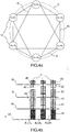
- the figures 4 and 4b illustrate an exemplary embodiment of a stacking device making it possible to temporarily maintain three space appendages on the same face of a space vehicle.
- each spatial appendage is fixed by four holding and release mechanisms 10 and that each mechanism 10 maintains two different spatial appendages. For this, six maintenance and release mechanisms are necessary.
- the figure 4a shows an example of the positioning of the holding and release mechanisms in a device for stacking spatial appendages.
- the support structures 20 of the three spatial appendages are stacked concentrically and have a shape such that the holding and release mechanisms can be distributed around the periphery of the spatial appendages on a circle C of center substantially equal to that stacking.
- two identical holding and release mechanisms 10 hold the appendages numbered A1 and A3, two others the appendages numbered A1 and A2 and two others the appendages numbered A2 and A3.
- the stacking device therefore has three different combinations of holding and release mechanism 10.
- a stacking device intended to stack n spatial appendages, n representing an integer strictly greater than two uses n associations of different holding and release mechanisms.
- the space appendages are held against the body 40 of the space vehicle in the stacking configuration by stacking tie rods 41 using sockets 42 fixed to the support structures 20 of the space appendages and spacers or cylinders. link 43.
- the function of the link cylinders 43 is to maintain the distance between the different spatial appendages A1, A2, A3.
- Each stacking tie rod 41 is tensioned by a stacking nut 44 and an ejection system 45 makes it possible to release the space appendages and ensure their deployment after its activation.
- the figure 4b illustrates the possible combinations of bushes 42 and link cylinders 43 in order to achieve the different configurations of the holding and release mechanisms 10 for this exemplary embodiment.
- the figure 5 shows an example of the configuration of holding and release mechanisms 10 in the case of a stacking of four spatial appendages A'1, A'2, A'3, A'4 on the same side of the vehicle spatial.
- four different combinations of bushings 42 and link cylinders 43 are required.
- the subject of the invention is also a space vehicle comprising an integer strictly greater than two space appendages.
- the space vehicle comprises at least one stacking device as presented previously configured to temporarily maintain in storage position at least three space appendages on the same face of the space vehicle.
Landscapes
- Engineering & Computer Science (AREA)
- Remote Sensing (AREA)
- Aviation & Aerospace Engineering (AREA)
- Automatic Assembly (AREA)
- Automobile Manufacture Line, Endless Track Vehicle, Trailer (AREA)
- Details Of Aerials (AREA)
- Liquid Crystal (AREA)
- Vehicle Cleaning, Maintenance, Repair, Refitting, And Outriggers (AREA)
Claims (9)
- Stapelvorrichtung für Raumfahrzeug, wobei die Vorrichtung n Raumansatzteile beinhaltet, wobei n eine Ganzzahl streng größer als 2 ist, und eine Vielzahl von Halte- und Lösemechanismen (10), wobei die Stapelvorrichtung konfiguriert ist, um zeitweilig die n Raumansatzteile auf einer selben Halterung des Raumfahrzeugs mithilfe der Halte- und Lösemechanismen (10) in gestapelter Position zu halten, wobei die Stapelvorrichtung Hülsen (42) beinhaltet, wobei jede Hülse an einer Stützstruktur (20) eines der Raumeinsatzteile montiert ist und die Befestigung eines der Halte- und Lösemechanismen (10) an einem Raumansatzteil ermöglicht; dadurch gekennzeichnet, dass die Anzahl, die Konfiguration und die Anordnung der Halte- und Lösemechanismen (10) so bestimmt sind:- dass jeder Halte- und Lösemechanismus (10) dimensioniert und konfiguriert ist, um n-1 Raumansatzteile in gestapelter Position zu halten; und- dass für jedes der n Raumansatzteile, jedes der anderen, sich von dem betrachteten Raumansatzteil unterscheidenden Raumansatzteile durch mindestens einen der Halte- und Lösemechanismen (10) in Position gehalten wird, welcher den Halt des betrachteten Raumansatzteils gewährleistet.
- Stapelvorrichtung nach Anspruch 1, dadurch gekennzeichnet, dass jeder Halte- und Lösemechanismus (10) ein Stapel-Zugelement (41) und Abstandsstücke oder Verbindungszylinder (43) beinhaltet, welche durch das Stapel-Zugelement durchquert werden; wobei das Stapel-Zugelement (41) eines jeden der Halte- und Lösemechanismen (10) eine bestimmte Anzahl an Hülsen (42) so durchquert, dass der Halt der Raumansatzteile, an welchen die Hülsen montiert sind, gewährleistet ist, wobei die unterschiedlichen Abstandsstücke, welche jeden Halte- und Lösemechanismus (10) bilden, so dimensioniert und in Bezug auf die durch das Stapel-Zugelement durchquerten Hülsen angeordnet sind, dass sie den Halt des Abstandes zwischen den unterschiedlichen Raumansatzteilen gewährleisten, welcher durch den betrachteten Halte- und Lösemechanismus (10) gehalten wird.
- Stapelvorrichtung nach Anspruch 2, dadurch gekennzeichnet, dass jeder Halte- und Lösemechanismus (10) zudem eine Stapelmutter (44) beinhaltet, welche es ermöglicht, das Stapel-Zugelement (41) des Mechanismus einzuspannen.
- Stapelvorrichtung nach einem der vorhergehenden Ansprüche, wobeijedes Raumansatzteil durch vier Halte- und Lösemechanismen (10) gehalten wird.
- Stapelvorrichtung nach Anspruch 4, wobeidie Anzahl n an Raumansatzteilen gleich 3 ist, wobei jeder Halte- und Lösemechanismus (10) konfiguriert ist, um den Halt von zwei Raumansatzteilen zu gewährleisten.
- Stapelvorrichtung nach einem der vorhergehenden Ansprüche, wobeidie Halte- und Lösemechanismen (10) auf einem Kreis befindlich sind, welcher auf den Mittelpunkt der Raumansatzteile zentriert ist.
- Stapelvorrichtung nach einem der vorhergehenden Ansprüche, wobeidie Halte- und Lösemechanismen (10) an der Peripherie der Raumansatzteile angeordnet sind.
- Stapelvorrichtung nach einem der vorhergehenden Ansprüche 1 bis 6, wobeidie Halte- und Lösemechanismen (10) in einem gemeinsamen Überlappungsbereich der unterschiedlichen Raumansatzteile angeordnet sind.
- Raumfahrzeug, wobei das Raumfahrzeug dadurch gekennzeichnet ist, dass es mindestens eine Stapelvorrichtung nach einem der vorhergehenden Ansprüche beinhaltet, dazu konfiguriert, zeitweilig die Raumansatzteile auf einer gleichen Seite des Raumfahrzeugs zu halten.
Applications Claiming Priority (1)
| Application Number | Priority Date | Filing Date | Title |
|---|---|---|---|
| FR1601448A FR3057245B1 (fr) | 2016-10-06 | 2016-10-06 | Dispositif de gerbage pour vehicule spatial et vehicule spatial associe |
Publications (2)
| Publication Number | Publication Date |
|---|---|
| EP3305667A1 EP3305667A1 (de) | 2018-04-11 |
| EP3305667B1 true EP3305667B1 (de) | 2020-09-02 |
Family
ID=58314280
Family Applications (1)
| Application Number | Title | Priority Date | Filing Date |
|---|---|---|---|
| EP17194966.2A Active EP3305667B1 (de) | 2016-10-06 | 2017-10-05 | Stapelvorrichtung für raumfahrzeug, und entsprechendes raumfahrzeug |
Country Status (5)
| Country | Link |
|---|---|
| US (1) | US10836514B2 (de) |
| EP (1) | EP3305667B1 (de) |
| CA (1) | CA2981803A1 (de) |
| ES (1) | ES2832548T3 (de) |
| FR (1) | FR3057245B1 (de) |
Families Citing this family (1)
| Publication number | Priority date | Publication date | Assignee | Title |
|---|---|---|---|---|
| CN113871845B (zh) * | 2021-09-28 | 2024-02-06 | 上海宇航系统工程研究所 | 一种多板天线锁紧释放装置 |
Family Cites Families (4)
| Publication number | Priority date | Publication date | Assignee | Title |
|---|---|---|---|---|
| DE2853070C3 (de) * | 1978-12-08 | 1981-10-29 | Messerschmitt-Bölkow-Blohm GmbH, 8000 München | Niederhaltersystem für entfaltbare oder entklappbare Trägerelemente an Raumflugkörpern |
| JPH10147298A (ja) * | 1996-11-20 | 1998-06-02 | Mitsubishi Electric Corp | 太陽電池パドル |
| FR2768401A1 (fr) * | 1997-09-17 | 1999-03-19 | Electrolux Zanussi Elettrodome | Dispositif d'extraction et d'escamotage d'un tirant de gerbage de panneaux d'un generateur solaire pour vehicule spatial |
| FR2822803B1 (fr) * | 2001-03-29 | 2003-08-15 | Cit Alcatel | Structure de generateur solaire pour satellite comprenant des calages entre panneaux |
-
2016
- 2016-10-06 FR FR1601448A patent/FR3057245B1/fr not_active Expired - Fee Related
-
2017
- 2017-10-05 EP EP17194966.2A patent/EP3305667B1/de active Active
- 2017-10-05 US US15/726,297 patent/US10836514B2/en active Active
- 2017-10-05 ES ES17194966T patent/ES2832548T3/es active Active
- 2017-10-06 CA CA2981803A patent/CA2981803A1/en active Pending
Non-Patent Citations (1)
| Title |
|---|
| None * |
Also Published As
| Publication number | Publication date |
|---|---|
| US20180099767A1 (en) | 2018-04-12 |
| ES2832548T3 (es) | 2021-06-10 |
| CA2981803A1 (en) | 2018-04-06 |
| FR3057245A1 (fr) | 2018-04-13 |
| FR3057245B1 (fr) | 2019-04-05 |
| US10836514B2 (en) | 2020-11-17 |
| EP3305667A1 (de) | 2018-04-11 |
Similar Documents
| Publication | Publication Date | Title |
|---|---|---|
| EP3259190B1 (de) | Weltraumfahrzeug mit pfosten zur bildung eines stapels, stapel mit mindestens zwei solchen fahrzeugen in einer trägerrakete und verfahren zur freigabe der fahrzeuge | |
| EP2716549B1 (de) | Satellit mit ausfahrbaren Nutzlastlademodulen | |
| EP3174794B2 (de) | Satellit mit einem optischen fotoapparat | |
| WO1996039328A1 (fr) | Dispositif adaptateur basculant pour l'emport de plusieurs charges utiles sur un meme lanceur | |
| FR2517626A1 (fr) | Engin spatial orbital, notamment satellite, a missions multiples | |
| FR3004166A1 (fr) | Systeme de satellites comportant deux satellites fixes l'un a l'autre et procede pour leur mise en orbite | |
| EP2256039A1 (de) | Durchgehender Zapfen mit flexiblen Elementen, und mit einem solchen Zapfen ausgestattetes Raumschiff | |
| EP3305667B1 (de) | Stapelvorrichtung für raumfahrzeug, und entsprechendes raumfahrzeug | |
| EP2650971B1 (de) | Antenne mit Mehrfachreflektoren für Telekommunikations-Satellit. | |
| WO2001062595A1 (fr) | Procede de fabrication d'une embase de support d'un satellite artificiel sur une plate-forme d'emport d'une pluralite de tels satellites | |
| EP2520494B1 (de) | Vorrichtung zum Schutz eines optischen Vielfachspiegelinstruments | |
| FR2983646A1 (fr) | Systeme a antenne deployable pour satellite et procede de deploiement | |
| CA2321359A1 (fr) | Dispositif de maintien et d'amortissement de choc et systeme d'arrimage temporaire d'un element sur une structure, equipe d'un tel dispositif | |
| FR2473011A1 (fr) | Agencement de satellite artificiel pourvu de generateurs solaires et d'antennes deployables | |
| EP3959141B1 (de) | Entfaltbare struktur mit grossen abmessungen | |
| EP2351148B1 (de) | Ausklappbare struktur und antennensystem mit membranen mit einer solchen struktur | |
| CA2364318C (fr) | Coffre pour ensemble de batteries d'accumulateurs electriques | |
| FR2780819A1 (fr) | Reflecteur d'antenne elastiquement deformable pour engin spatial | |
| FR3130393A1 (fr) | Agencement d'antennes TTC pour satellite plat | |
| EP2289124A2 (de) | Antennensystemanordnung mit eingebauter selbsttragender antenne und entsprechendes antennensystem | |
| EP2927992B1 (de) | Mechanisches halterungssystem zum fixieren einer batterie in einem röhrenförmigen fach | |
| FR2972859A1 (fr) | Dispositif de commutation de reflecteurs pour une antenne a faisceau commutable | |
| FR3101857A1 (fr) | Dispositif de déploiement d’une surface | |
| WO2024246440A1 (fr) | Ecran déployable pour télescope spatial | |
| FR3098651A1 (fr) | Dispositif de deploiement tridimensionnel |
Legal Events
| Date | Code | Title | Description |
|---|---|---|---|
| PUAI | Public reference made under article 153(3) epc to a published international application that has entered the european phase |
Free format text: ORIGINAL CODE: 0009012 |
|
| STAA | Information on the status of an ep patent application or granted ep patent |
Free format text: STATUS: THE APPLICATION HAS BEEN PUBLISHED |
|
| AK | Designated contracting states |
Kind code of ref document: A1 Designated state(s): AL AT BE BG CH CY CZ DE DK EE ES FI FR GB GR HR HU IE IS IT LI LT LU LV MC MK MT NL NO PL PT RO RS SE SI SK SM TR |
|
| AX | Request for extension of the european patent |
Extension state: BA ME |
|
| STAA | Information on the status of an ep patent application or granted ep patent |
Free format text: STATUS: REQUEST FOR EXAMINATION WAS MADE |
|
| 17P | Request for examination filed |
Effective date: 20180925 |
|
| RBV | Designated contracting states (corrected) |
Designated state(s): AL AT BE BG CH CY CZ DE DK EE ES FI FR GB GR HR HU IE IS IT LI LT LU LV MC MK MT NL NO PL PT RO RS SE SI SK SM TR |
|
| RIC1 | Information provided on ipc code assigned before grant |
Ipc: B64G 1/22 20060101AFI20200313BHEP |
|
| GRAP | Despatch of communication of intention to grant a patent |
Free format text: ORIGINAL CODE: EPIDOSNIGR1 |
|
| STAA | Information on the status of an ep patent application or granted ep patent |
Free format text: STATUS: GRANT OF PATENT IS INTENDED |
|
| INTG | Intention to grant announced |
Effective date: 20200424 |
|
| GRAS | Grant fee paid |
Free format text: ORIGINAL CODE: EPIDOSNIGR3 |
|
| GRAA | (expected) grant |
Free format text: ORIGINAL CODE: 0009210 |
|
| STAA | Information on the status of an ep patent application or granted ep patent |
Free format text: STATUS: THE PATENT HAS BEEN GRANTED |
|
| AK | Designated contracting states |
Kind code of ref document: B1 Designated state(s): AL AT BE BG CH CY CZ DE DK EE ES FI FR GB GR HR HU IE IS IT LI LT LU LV MC MK MT NL NO PL PT RO RS SE SI SK SM TR |
|
| REG | Reference to a national code |
Ref country code: GB Ref legal event code: FG4D Free format text: NOT ENGLISH |
|
| REG | Reference to a national code |
Ref country code: AT Ref legal event code: REF Ref document number: 1308553 Country of ref document: AT Kind code of ref document: T Effective date: 20200915 Ref country code: CH Ref legal event code: EP |
|
| REG | Reference to a national code |
Ref country code: DE Ref legal event code: R096 Ref document number: 602017022695 Country of ref document: DE |
|
| REG | Reference to a national code |
Ref country code: IE Ref legal event code: FG4D Free format text: LANGUAGE OF EP DOCUMENT: FRENCH |
|
| REG | Reference to a national code |
Ref country code: CH Ref legal event code: NV Representative=s name: SERVOPATENT GMBH, CH |
|
| REG | Reference to a national code |
Ref country code: LT Ref legal event code: MG4D |
|
| PG25 | Lapsed in a contracting state [announced via postgrant information from national office to epo] |
Ref country code: FI Free format text: LAPSE BECAUSE OF FAILURE TO SUBMIT A TRANSLATION OF THE DESCRIPTION OR TO PAY THE FEE WITHIN THE PRESCRIBED TIME-LIMIT Effective date: 20200902 Ref country code: NO Free format text: LAPSE BECAUSE OF FAILURE TO SUBMIT A TRANSLATION OF THE DESCRIPTION OR TO PAY THE FEE WITHIN THE PRESCRIBED TIME-LIMIT Effective date: 20201202 Ref country code: SE Free format text: LAPSE BECAUSE OF FAILURE TO SUBMIT A TRANSLATION OF THE DESCRIPTION OR TO PAY THE FEE WITHIN THE PRESCRIBED TIME-LIMIT Effective date: 20200902 Ref country code: BG Free format text: LAPSE BECAUSE OF FAILURE TO SUBMIT A TRANSLATION OF THE DESCRIPTION OR TO PAY THE FEE WITHIN THE PRESCRIBED TIME-LIMIT Effective date: 20201202 Ref country code: GR Free format text: LAPSE BECAUSE OF FAILURE TO SUBMIT A TRANSLATION OF THE DESCRIPTION OR TO PAY THE FEE WITHIN THE PRESCRIBED TIME-LIMIT Effective date: 20201203 Ref country code: HR Free format text: LAPSE BECAUSE OF FAILURE TO SUBMIT A TRANSLATION OF THE DESCRIPTION OR TO PAY THE FEE WITHIN THE PRESCRIBED TIME-LIMIT Effective date: 20200902 Ref country code: LT Free format text: LAPSE BECAUSE OF FAILURE TO SUBMIT A TRANSLATION OF THE DESCRIPTION OR TO PAY THE FEE WITHIN THE PRESCRIBED TIME-LIMIT Effective date: 20200902 |
|
| REG | Reference to a national code |
Ref country code: NL Ref legal event code: MP Effective date: 20200902 |
|
| REG | Reference to a national code |
Ref country code: AT Ref legal event code: MK05 Ref document number: 1308553 Country of ref document: AT Kind code of ref document: T Effective date: 20200902 |
|
| PG25 | Lapsed in a contracting state [announced via postgrant information from national office to epo] |
Ref country code: PL Free format text: LAPSE BECAUSE OF FAILURE TO SUBMIT A TRANSLATION OF THE DESCRIPTION OR TO PAY THE FEE WITHIN THE PRESCRIBED TIME-LIMIT Effective date: 20200902 Ref country code: LV Free format text: LAPSE BECAUSE OF FAILURE TO SUBMIT A TRANSLATION OF THE DESCRIPTION OR TO PAY THE FEE WITHIN THE PRESCRIBED TIME-LIMIT Effective date: 20200902 Ref country code: RS Free format text: LAPSE BECAUSE OF FAILURE TO SUBMIT A TRANSLATION OF THE DESCRIPTION OR TO PAY THE FEE WITHIN THE PRESCRIBED TIME-LIMIT Effective date: 20200902 |
|
| PG25 | Lapsed in a contracting state [announced via postgrant information from national office to epo] |
Ref country code: PT Free format text: LAPSE BECAUSE OF FAILURE TO SUBMIT A TRANSLATION OF THE DESCRIPTION OR TO PAY THE FEE WITHIN THE PRESCRIBED TIME-LIMIT Effective date: 20210104 Ref country code: RO Free format text: LAPSE BECAUSE OF FAILURE TO SUBMIT A TRANSLATION OF THE DESCRIPTION OR TO PAY THE FEE WITHIN THE PRESCRIBED TIME-LIMIT Effective date: 20200902 Ref country code: CZ Free format text: LAPSE BECAUSE OF FAILURE TO SUBMIT A TRANSLATION OF THE DESCRIPTION OR TO PAY THE FEE WITHIN THE PRESCRIBED TIME-LIMIT Effective date: 20200902 Ref country code: EE Free format text: LAPSE BECAUSE OF FAILURE TO SUBMIT A TRANSLATION OF THE DESCRIPTION OR TO PAY THE FEE WITHIN THE PRESCRIBED TIME-LIMIT Effective date: 20200902 Ref country code: SM Free format text: LAPSE BECAUSE OF FAILURE TO SUBMIT A TRANSLATION OF THE DESCRIPTION OR TO PAY THE FEE WITHIN THE PRESCRIBED TIME-LIMIT Effective date: 20200902 |
|
| PG25 | Lapsed in a contracting state [announced via postgrant information from national office to epo] |
Ref country code: IS Free format text: LAPSE BECAUSE OF FAILURE TO SUBMIT A TRANSLATION OF THE DESCRIPTION OR TO PAY THE FEE WITHIN THE PRESCRIBED TIME-LIMIT Effective date: 20210102 Ref country code: AT Free format text: LAPSE BECAUSE OF FAILURE TO SUBMIT A TRANSLATION OF THE DESCRIPTION OR TO PAY THE FEE WITHIN THE PRESCRIBED TIME-LIMIT Effective date: 20200902 Ref country code: AL Free format text: LAPSE BECAUSE OF FAILURE TO SUBMIT A TRANSLATION OF THE DESCRIPTION OR TO PAY THE FEE WITHIN THE PRESCRIBED TIME-LIMIT Effective date: 20200902 |
|
| REG | Reference to a national code |
Ref country code: DE Ref legal event code: R097 Ref document number: 602017022695 Country of ref document: DE |
|
| REG | Reference to a national code |
Ref country code: ES Ref legal event code: FG2A Ref document number: 2832548 Country of ref document: ES Kind code of ref document: T3 Effective date: 20210610 |
|
| PG25 | Lapsed in a contracting state [announced via postgrant information from national office to epo] |
Ref country code: SK Free format text: LAPSE BECAUSE OF FAILURE TO SUBMIT A TRANSLATION OF THE DESCRIPTION OR TO PAY THE FEE WITHIN THE PRESCRIBED TIME-LIMIT Effective date: 20200902 Ref country code: MC Free format text: LAPSE BECAUSE OF FAILURE TO SUBMIT A TRANSLATION OF THE DESCRIPTION OR TO PAY THE FEE WITHIN THE PRESCRIBED TIME-LIMIT Effective date: 20200902 Ref country code: LU Free format text: LAPSE BECAUSE OF NON-PAYMENT OF DUE FEES Effective date: 20201005 |
|
| PLBE | No opposition filed within time limit |
Free format text: ORIGINAL CODE: 0009261 |
|
| STAA | Information on the status of an ep patent application or granted ep patent |
Free format text: STATUS: NO OPPOSITION FILED WITHIN TIME LIMIT |
|
| REG | Reference to a national code |
Ref country code: BE Ref legal event code: MM Effective date: 20201031 |
|
| 26N | No opposition filed |
Effective date: 20210603 |
|
| PG25 | Lapsed in a contracting state [announced via postgrant information from national office to epo] |
Ref country code: BE Free format text: LAPSE BECAUSE OF NON-PAYMENT OF DUE FEES Effective date: 20201031 Ref country code: DK Free format text: LAPSE BECAUSE OF FAILURE TO SUBMIT A TRANSLATION OF THE DESCRIPTION OR TO PAY THE FEE WITHIN THE PRESCRIBED TIME-LIMIT Effective date: 20200902 Ref country code: SI Free format text: LAPSE BECAUSE OF FAILURE TO SUBMIT A TRANSLATION OF THE DESCRIPTION OR TO PAY THE FEE WITHIN THE PRESCRIBED TIME-LIMIT Effective date: 20200902 |
|
| PG25 | Lapsed in a contracting state [announced via postgrant information from national office to epo] |
Ref country code: IE Free format text: LAPSE BECAUSE OF NON-PAYMENT OF DUE FEES Effective date: 20201005 Ref country code: IT Free format text: LAPSE BECAUSE OF FAILURE TO SUBMIT A TRANSLATION OF THE DESCRIPTION OR TO PAY THE FEE WITHIN THE PRESCRIBED TIME-LIMIT Effective date: 20200902 |
|
| PG25 | Lapsed in a contracting state [announced via postgrant information from national office to epo] |
Ref country code: TR Free format text: LAPSE BECAUSE OF FAILURE TO SUBMIT A TRANSLATION OF THE DESCRIPTION OR TO PAY THE FEE WITHIN THE PRESCRIBED TIME-LIMIT Effective date: 20200902 Ref country code: MT Free format text: LAPSE BECAUSE OF FAILURE TO SUBMIT A TRANSLATION OF THE DESCRIPTION OR TO PAY THE FEE WITHIN THE PRESCRIBED TIME-LIMIT Effective date: 20200902 Ref country code: CY Free format text: LAPSE BECAUSE OF FAILURE TO SUBMIT A TRANSLATION OF THE DESCRIPTION OR TO PAY THE FEE WITHIN THE PRESCRIBED TIME-LIMIT Effective date: 20200902 |
|
| PG25 | Lapsed in a contracting state [announced via postgrant information from national office to epo] |
Ref country code: MK Free format text: LAPSE BECAUSE OF FAILURE TO SUBMIT A TRANSLATION OF THE DESCRIPTION OR TO PAY THE FEE WITHIN THE PRESCRIBED TIME-LIMIT Effective date: 20200902 |
|
| PG25 | Lapsed in a contracting state [announced via postgrant information from national office to epo] |
Ref country code: NL Free format text: LAPSE BECAUSE OF NON-PAYMENT OF DUE FEES Effective date: 20200923 |
|
| PGFP | Annual fee paid to national office [announced via postgrant information from national office to epo] |
Ref country code: GB Payment date: 20250918 Year of fee payment: 9 |
|
| PGFP | Annual fee paid to national office [announced via postgrant information from national office to epo] |
Ref country code: FR Payment date: 20250922 Year of fee payment: 9 |
|
| REG | Reference to a national code |
Ref country code: CH Ref legal event code: U11 Free format text: ST27 STATUS EVENT CODE: U-0-0-U10-U11 (AS PROVIDED BY THE NATIONAL OFFICE) Effective date: 20251101 |
|
| PGFP | Annual fee paid to national office [announced via postgrant information from national office to epo] |
Ref country code: DE Payment date: 20250916 Year of fee payment: 9 |
|
| PGFP | Annual fee paid to national office [announced via postgrant information from national office to epo] |
Ref country code: CH Payment date: 20251101 Year of fee payment: 9 |
|
| PGFP | Annual fee paid to national office [announced via postgrant information from national office to epo] |
Ref country code: ES Payment date: 20251104 Year of fee payment: 9 |